

Teleste CFO OP-X series User Manual
CFO OP-X Series
User Manual
Unmanaged Fast Ethernet Switch
CES User Manual, 59300180, rev002
CES

Contents
CES Fast Ethernet Switch Introduction ......................................................................................................1
General ...................................................................................................................................................1
Switching Methods ..................................................................................................................................1
CAT5 Cable Connection ..........................................................................................................................2
Simple Network management Connection (SNMP)................................................................................2
Installation .....................................................................................................................................................3
Quick Instructions ...................................................................................................................................3
CES Front Panel ............................................................................................................................................4
CES Switch Mechanical Connections .....................................................................................................4
How to Unplug or Plug-in the SFP Transceiver Module ..........................................................................5
Connections ..................................................................................................................................................6
Up-link Port Connections .......................................................................................................................6
Local Port Connections ..........................................................................................................................6
Management Connection .......................................................................................................................7
Fibre Connection ....................................................................................................................................7
IP Confi g Tool ...............................................................................................................................................8
Introduction .............................................................................................................................................8
System Requirements .............................................................................................................................8
How to Get the IP Confi g Tool .................................................................................................................8
How to Install the IP Confi g Tool .............................................................................................................8
Operating ................................................................................................................................................8
Device List Page ....................................................................................................................................9
How to Confi gure the Switch ...................................................................................................................9
Selected Device Page .........................................................................................................................10
Port Confi guration Page ..................................................................................................................... 11
Notes on the IP Confi guration Tool .......................................................................................................12
Trouble Shooting ...................................................................................................................................12
Firmware Upgrade via IP Confi g Tool ...................................................................................................12
IP Confi g Tool and Firmware Versions ..................................................................................................12
Glossary ................................................................................................................................................. 13-15
Technical Specifi cations ........................................................................................................................... 16
Copyright Acknowledgements ..................................................................................................................17
CES Series User Manual rev002

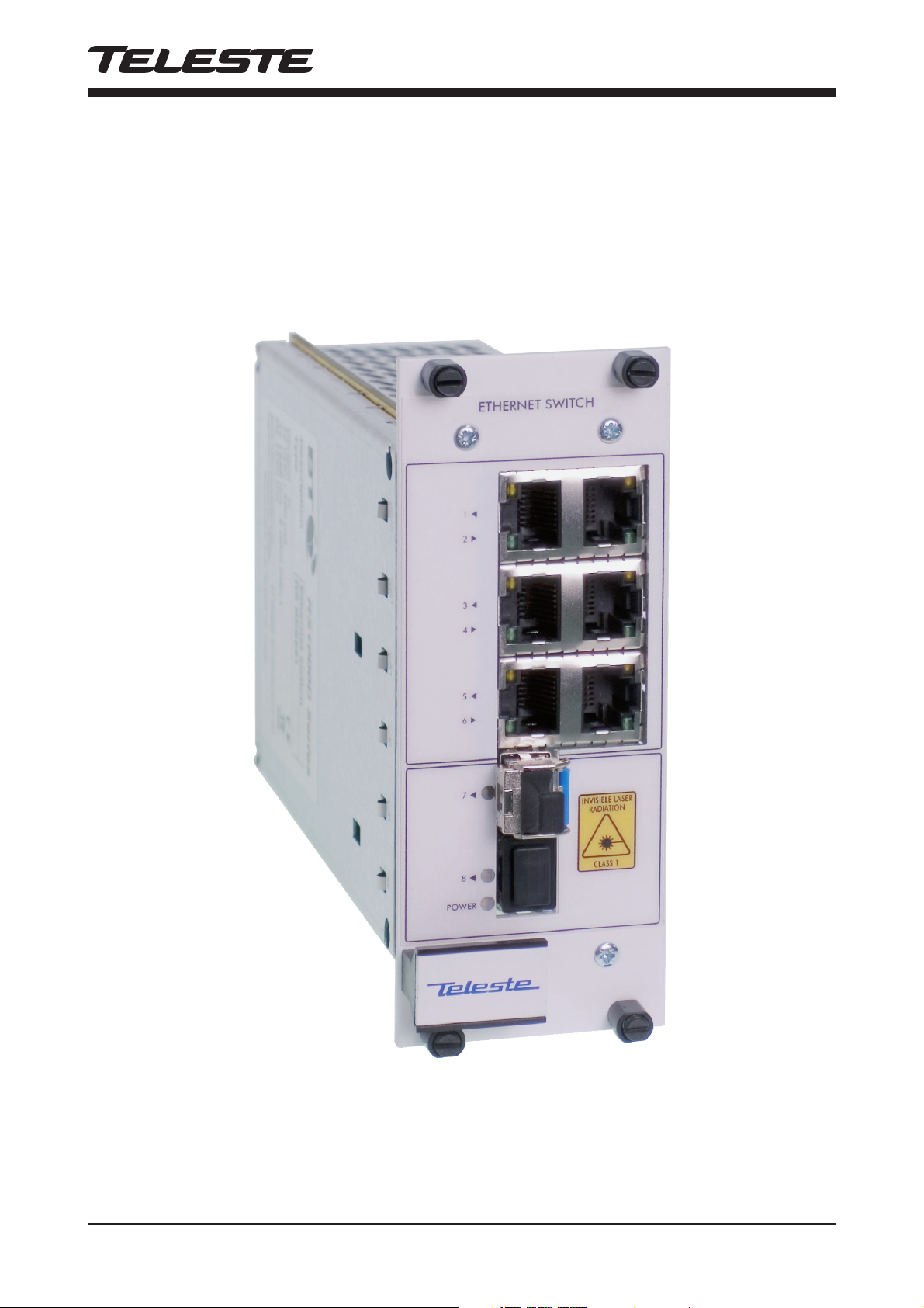
CES Fast Ethernet Switch Introduction
Stand-alone 8 port Fast Ethernet switch with 6 x 10/100BaseTx Local ports and 2 x 100Base-Fx Up-link ports, multimode or
singlemode devices
Welcome, and thank you for purchasing Teleste’s CFO OP-X Products.
E
x6
M
gmt
General
CES is an unmanaged (supports limited management) fi eld hardened
stand-alone Fast Ethernet Switch for video networking applications.
The CES supports SNMP management, port confi guration, port alarms,
QoS (layer 2 and 3) and port mirroring.
Switching Methods
The Switch stores every incoming packet and scans this for errors,
usually by checking the frame CRC (cyclic redundancy check sum).
If any errors are found or detected the packet is discarded. In addition each frame is checked for size. Undersized packets (less than 64
Bytes) and oversized packets (more than 1518 bytes (*)) are also
discarded. Once these basic checks have been carried out the
Switch can then start learning packet source and destination information. (*) When implementing Ethernet MAC tagging maximum Ethernet packet length is increased to 1522 bytes.
The Switch needs to make a decision regarding which port(s)
the packet is to be forwarded to. This decision is based upon
the MAC tables that are maintained and updated automatically by
the Switch. The process is known as Layer 2 Switching. When fi rst
powered on the MAC tables within the Switch are empty. When
a packet is received on a port the Switch does not know where
the destination MAC address is located. The Switch learns
the address by ‘fl ooding’ the packet out to all ports. Eventually,
the destination node responds, the address is located and the Switch
remembers the destination port. In simplistic terms; when a Switch
receives a packet on a port it stores the source MAC address in
the MAC table that corresponds to that Port. The fl ooding technique
is always used with Broadcast and Multicast packets. If the Switch is
equipped with multicast management then multicast packets will not
be fl ooded.
A MAC table can hold up to 2 K entries; and with a total packet
memory of 1 Mbit this is adequate for normal networks. Naturally,
devices will be disconnected from Ports during the life of a network.
If the MAC table did not automatically monitor for idle nodes the table
would become full. If a node has been idle for more than a few
seconds the source and destination information for that node will be
deleted from the table. This is commonly known as the ‘age time’.
MAC table size is normally always large enough for industrial networks. Packet memory size on the other hand can affect performance and ability to handle short high load/overload situations when
an event occurs in a control network or similar industrial network.
CES Series User Manual rev002 1

CAT5 Cable Connection
All CAT5 ports support extended 150 m distances when using high
quality CAT5e or better cables. Both straight and cross connected
RJ-45 cables can be used for CAT5 connection. All CAT5 ports
support MDI/MDIX by automatically accepting both straight and
crossover Ethernet UTP cables. All CAT5 ports support also autonegotiation protocol, detects the various modes that exist in the
device on the other end of the wire and advertises it own abilities to
automatically confi gure the highest performance mode of interoperation. The Switch also automatically corrects polarity errors. Furthermore the CAT5 UTP ports have isolation barriers between the signal
lines and the internal electronics withstanding 1500 Vrms (1 minute).
Simple Network Management Protocol (SNMP)
The CES switch supports SNMPv2c. SNMP enables network
administrators and control engineers to manage network performance, fi nd and solve network problems, and plan for network
growth. One feature of SNMP is that the SNMP agent (in this case
a CES switch) can send SNMP traps to one or more SNMP Hosts.
SNMP traps mean system alarms such as a port link loss or a port
enabled for port alarms or the switch temperature exceeding
a predefi ned threshold.
2 CES Series User Manual rev002
Installation
Quick instructions
Install the fi eld hardened stand-alone CES device
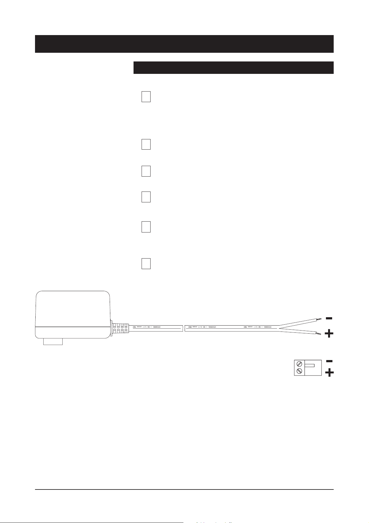
(3U high, 10HP wide) to the CMA module adapter. A 12 V
1
supply voltage is provided by a CPS23x mains adapter.
Alternatively, install the rack mount CES device into a CSRinstallation frame equipped with a CPS power supply.
Switch on the power and see that all indicator LEDs on the
2
front panel are going thru a routine checking cycle.
Connect all necessary Ethernet cables.
Note! Management connection to the device can be created
3
via any of local port, although port 1 is the recommended.
Open IP Confi g tool on the computer connected to the
4
Switch and confi gure all necessary settings.
Make sure that the port indicator led on the front panel is lit
green on the ports where cables are connected. If the
5
indicator led is dark, the Ethernet connection does not
operate at that port.
Default network addresses for the devices are are
the following:
6
10.9.96.30 (IP address)
255.255.255.0 (Netmask address)
Picture 1. CPS23x series power supply with connector.
CES Series User Manual rev002 3
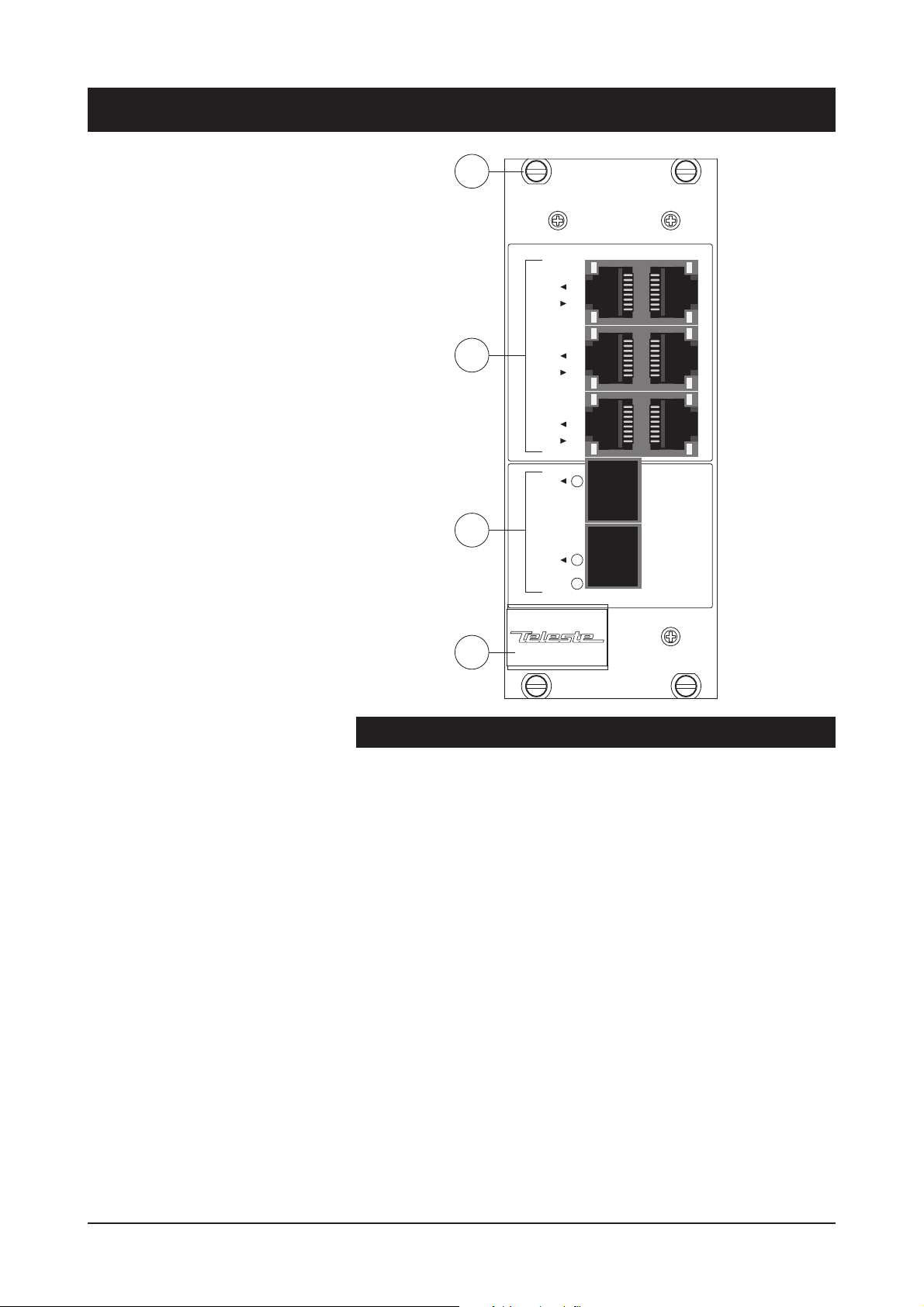
CES Front Panel
1
ETHERNET SWITCH
1
2
2
3
4
5
6
7
3
8
POWER
4
CES Switch Mechanical Connections
1. Locking screws (4 pcs).
2.
6 x Fast Ethernet (10/100Base-Tx) local ports (RJ-45 female)
and indicator leds
.
3. 2 x Fast (100Base) up-link ports. Up-link ports are equipped with
small form-factor pluggable (SFP) plug-in optical transceivers
(LC connector). If only one up-link port is required, the second
port can be left unused.
4. Handle
4 CES Series User Manual rev002
 Loading...