

Teleste AC1000 User Manual
User Manual AC1000
59300001 Rev.003
Broadband Cable Networks December 17, 2002 1(11)
A: AC1000 AMPLIFIER PLATFORM
General
The AC1000 is a single active output amplifier with
high gain. The amplifier can be used for distribution
purpose at high gain mode and also as a line
amplifier with lower gain. It is extremely versatile
and scalable through a wide range of plug-in
options. The amplifier platform can also be easily
upgraded to operate as a fibre node. The part A of
this document is devoted to procedures possible
while the Access platform is used as an amplifier.
Similar information concerning the fibre node will be
found in part B of this document respectively.
Installation
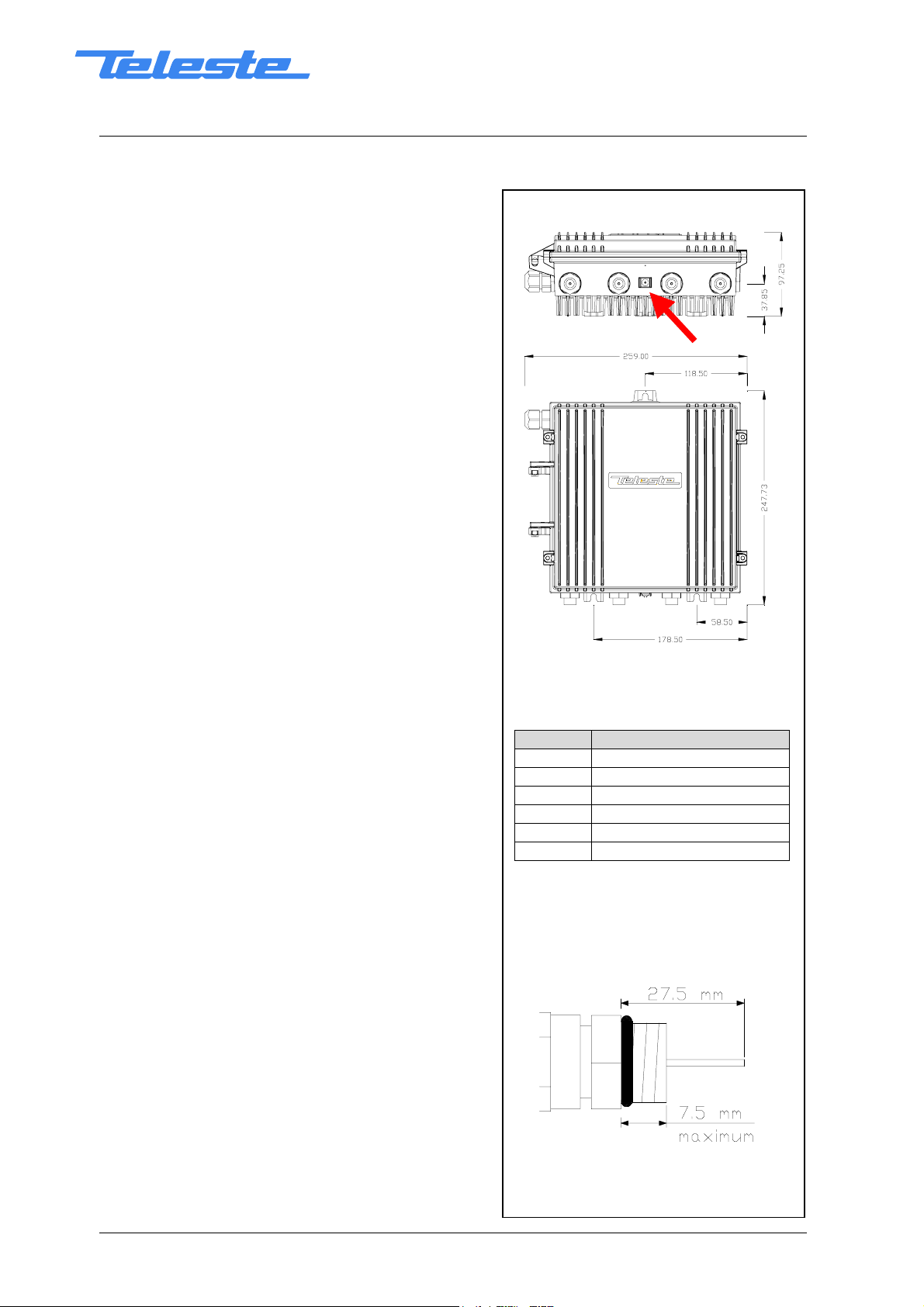
TheAC1000canbeinstalledeitherintoastreet
cabinet or to an outdoor environment. The node
should be installed in a vertical position so that the
external cable connectors are underneath. Secure
the housing with three mounting brackets – see
fig.1 for the positions of mounting brackets as well
as other installation dimensions.
The cover opens with the hinges to the left. The
open cover can be removed by first opening the
cover into a 90 degrees angle and the lifting it off
the hinges. Close the lid by tightening the four
retaining bolts in a diagonal sequence. Before
closing the lid check that
- nothing is trapped between the lid and the case
- all case gaskets are in their correct positions
A sufficient tightening torque is 3 Nm. Ensure that
the lid seats evenly on the rubber gasket. The class
of enclosure is IP54.
To ground the amplifier housing connect at least
2
4mm
the grounding point (see the arrow in fig.1).
grounding wire (Cu) from a proper earth to
8602013
Fig.1. Dimensions of the AC1000
housing and the grounding point
location
Type Description
AC6110 0 dB input module
AC6112 1/12 dB tap
AC6120 0 dB output module
AC6124 two-way splitter
AC6128 2/9 dB tap
AC6111 termination module
Table 1. List of available input and
output connector modules
ac1000_rf
Cable connections
Underneath the AC1000 amplifier there are four
cable connection points: input, input bypass/output
and two outputs. The amount and function of the
actual connectors varies with the chosen
configuration. All coaxial outputs have a standard
PG11 thread and they accept any KDC type
adapter or connector. A suitable length of the cable
inner conductor exposed for the connectors is
approximately 20 mm (fig.2).
Fig.2. RF cable connector
printed on December 17, 2002
User Manual AC1000
59300001 Rev.003
Broadband Cable Networks December 17, 2002 2(11)
Power feed
The supply voltage of the remote powered amplifier (27...65 V AC or ± 33...90 V
DC) can be fed through any of the cable connections by inserting a fuse to the
corresponding fuseholder (fig.3 pos.22). When a cable connection is used for
powering, the maximum supply current is 8.0 A.
The power intake of the remote powered amplifier may also be done externally
via the cable feed-through that is located on the upper left corner of the
amplifier. In this case the maximum supply current is 12.0 A.
External power can also be fed through the amplifier into the network. Maximum
feed-through current is 8.0 A per port.
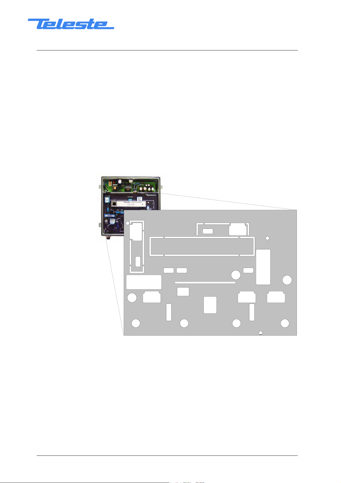
Connectors and plug-in unit slots
11
10
18
9
5
8
22
1
Fig.3. AC1000 plug-in placement,
1) Input
2) Input by-pass / Output 3 (*)
3) Output 2
4) Output 1
5) Input test point, -20 dB transformer
6) Test signal injection point, -30 dB
transformer
7) Output test point, -20 dB directional
coupler
8) Input module (see table 1)
9) Input diplex filter
10) Input attenuator
11) Input equaliser
13
12
17
21
22
234
14
15
16
6
20
22
7
19
12) Slot for elementmanagement
transponder module
13) Interstage attenuator
14) Interstage equaliser
15) Output diplexfilter
16) Return path input attenuator
17) Return path equaliser
18) Return path attenuator
19) Output module 1 (see table 1)
20) Output module 2 (see table 1)
21) Input by-pass / Output 3 jumper (*)
22) Fuse(s)
*) See chapter Jumper settings (n ext page)
printed on December 17, 2002

User Manual AC1000
59300001 Rev.003
Broadband Cable Networks December 17, 2002 3(11)
Adjustments
Forward path
The AC1000 is available in many configurations to fill various network
requirements. The amplifier is delivered according to the specifications defined
in the ordering code. Optional return path operation needs plug-in diplex filters.
The available diplex filter types are CXF030 (30/47 MHz), CXF042 (42/54 MHz),
CXF050 (50/70 MHz) and CXF065 (65/85 MHz). It is also possible to order the
amplifier with no diplexers, in which case the diplex filters are replaced by
forward path jumpers CXF000. In addition an optional element management
transponder module is available allowing remote monitoring and controlling of
the amplifier.
The input and output amplifier stages are both based on high performance
solutions which allows the operator to set this amplifier’s outputs for trunk or
distribution levels. Input and output modules are passive plug-ins used to
control the outputs – see table 1. During the adjustment the plug-in unit
positions for input and output modules must be equipped at least with the 0 dB
modules.
Install the interstage equaliser and attenuator plug-ins (fig.3 pos.14 and 13)
according the network plan. The network plan should specify exact signal
values.
Set the output slope of the amplifier according to the network plan calculation by
means of input equaliser (fig.3 pos.11). The signal can be measured at the
-20 dB output test point (fig.3 pos.7). To reach finally the desired output level
select an appropriate input attenuator for the plug-in position 10 (fig.3). Note! If
the income level of the amplifier is quite high or unknown, replace the input
attenuator in position 10 (fig.3) with an attenuator of rather big attenuation value
e.g. JDA915 (15 dB, 860 MHz).
Return path
The return path adjustment is based on unity gain principle such that the return
path gain of the amplifier station exactly matches the loss of the cable following
it (i.e., the cable span toward the headend). Inject a signal of known power into
the test signal injection point (fig.3 pos.6) in the amplifier and measure the
output level in the headend. Once the signal is received at the headend, it can
be measured and the information sent into the forward path as a narrowband
signal. This signal can be detected from the -20 dB test point (fig.3 pos. 7).
Adjust the gain (fig.3 pos. 18) and slope (fig.3 pos.17) of the amplifier until the
target level is produced.
The return path requires a specific signal level for proper operation. The ideal
level at the amplifier is based on the incoming power and the maximum loss
through which that signal must travel on its way to the amplifier. A typical
individual channel level at the return path input is in range of 70…80 dBµV.
Usually the return path input attenuator (fig.3 pos.16) is set to 0 dB. If the
amplifier is used as the last amplifier in a network and it is followed with a
distribution network with an exceptional low attenuation, an extra attenuation
can be added. Attenuators of the JDA series type ranging from 0 dB to 20 dB in
1 dB steps are available.
If the return path is not in use, the return path attenuator (fig.3 pos.18) should
be removed. The termination towards the headend will then be completed
automatically. Alternatively the return path can be terminated towards
printed on December 17, 2002
User Manual AC1000
59300001 Rev.003
Broadband Cable Networks December 17, 2002 4(11)
client/network by replacing the return path input path attenuator (fig.3 pos.16)
with an attenuator of big attenuation value e.g. JDA920 (20dB, 860 MHz) or with
a 75 ohm termination plug-in JDA975.
Utilising remotely controlled ingress switch allows the operator to isolate
problems in return path and take corrective actions. The return path signal can
either be cut off (i.e. signal is attenuated more than 50 dB) or be attenuated by
6 dB. As default factory setting the ingress switch is set to 0 dB position. Since
homes may not always be connected to return path services, the return path RF
signal should be cut off by the management unit. Once connected, the ingress
switch should be set to 0 dB position.
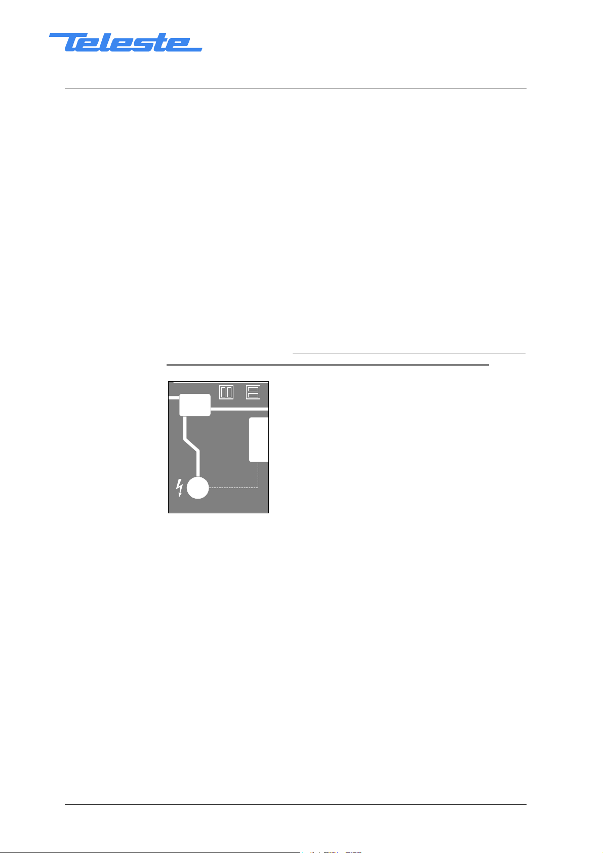
Jumper settings
The function of the Input by-pass / Output 3 port (fig.3 pos.2) is selected with a
jumper (fig.3 pos.21). The jumper positions are displayed in the protective
covering inside the amplifier housing (see fig.4). When the jumper is in the bypass position, the input signal is passed straight through the amplifier into the
port in question. In case the jumper is in the output 3 position, the output signal
is fed into this port. Note! The output module 2 slot (fig.3 pos.20) has to be
fitted with a proper module (splitter or tap) to enable the third output port.
by-pass / output 3
fuse
by-pass / output 3
Fig.4. By-pass / Output 3 jumper location and settings
printed on December 17, 2002
 Loading...