

Telesis XPRESS EP/TLM Quick Start Manual
XPRESS
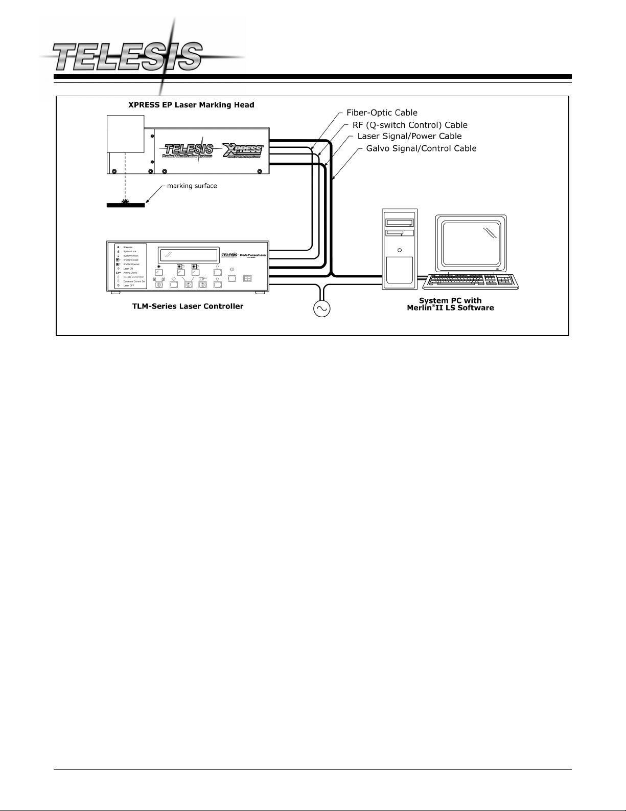
XPRESS EP/TLM Laser Marking System General Arrangment
™
EP / TLM Laser Marking System
System Overview
The XPRESS EP/TLM is an advanced, fiber-coupled diode
end-pumped laser marking system. The laser beam quality and
Q-switched pulse characteristics are optimized for applications
that require high beam quality and stability. This system is a very
good choice for general-purpose laser marking, scribing,
trimming, and other material processing applications.
The XPRESS-series unique L-shaped design features a continuous
wave (CW)/Q-switched Nd:YVO
remote fiber-coupled diode pumping source. With average diode
life of greater than 20,000 working hours the XPRESS EP offers
the user “best-in-class” reliability.
The robust mechanical and optical design allows the Telesis
XPRESS EP to operate in industrial conditions with respect to
shock, vibration, and dust.
The XPRESS EP/TLM laser marking system offers these
advantages:
end-pumped laser with a
4
• Reliable, long, maintenance-free performance
• Compact size and modular construction
• Remote, fiber-coupled pumping diode
• Exceptional beam quality and stable output power
• Active (thermo-electrical) temperature control of the
laser crystal and pumping diode
• Active AO Q-switching
• Air cooling
• Visible red diode for dry run / positioning
• Large digital display for marker status, settings, and
error condition monitoring
• Standard 115/230VAC operation
• DoD-compliant Unique Identification (UID) marking
System Configuration
The XPRESS EP/TLM basic package consists of the following:
• TLM-Series Laser Controller – contains pumping diode,
RF driver, and other electrical components
• Fiber Optic / Umbilical Assembly
• XPRESS EP Laser Marking Head – contains sealed
resonator, beam expander, turning mirror, galvanometer
assembly, visible red light positioning laser
• Software – Merlin II LS Laser Marking Software
• System Computer – supplied by Telesis or by customer
The modular design allows for major components to be easily
replaced and returned to Telesis if in need of repair.
Laser System Options
• Desktop computer or Notebook computer with powered
cardbus-to-PCI expansion enclosure
• Externally-mounted focus-finder diode
• Tool post w/ manual hand crank for z-axis adjustment
• Pushbutton station (start/abort)
• I/O Options:
TTL via PCI-DIO24 Card (Kit #53920)
Opto-isolated via Merlin DCIO Module (Kit #53928)
TMC090 Controller (for auxiliary axes; additional I/O)
• Programmable X-, Y, or Z-axis (TMC090 required)
• Rotary drive fixture (TMC090 required)
Doc. No. 40213 – 1 of 6
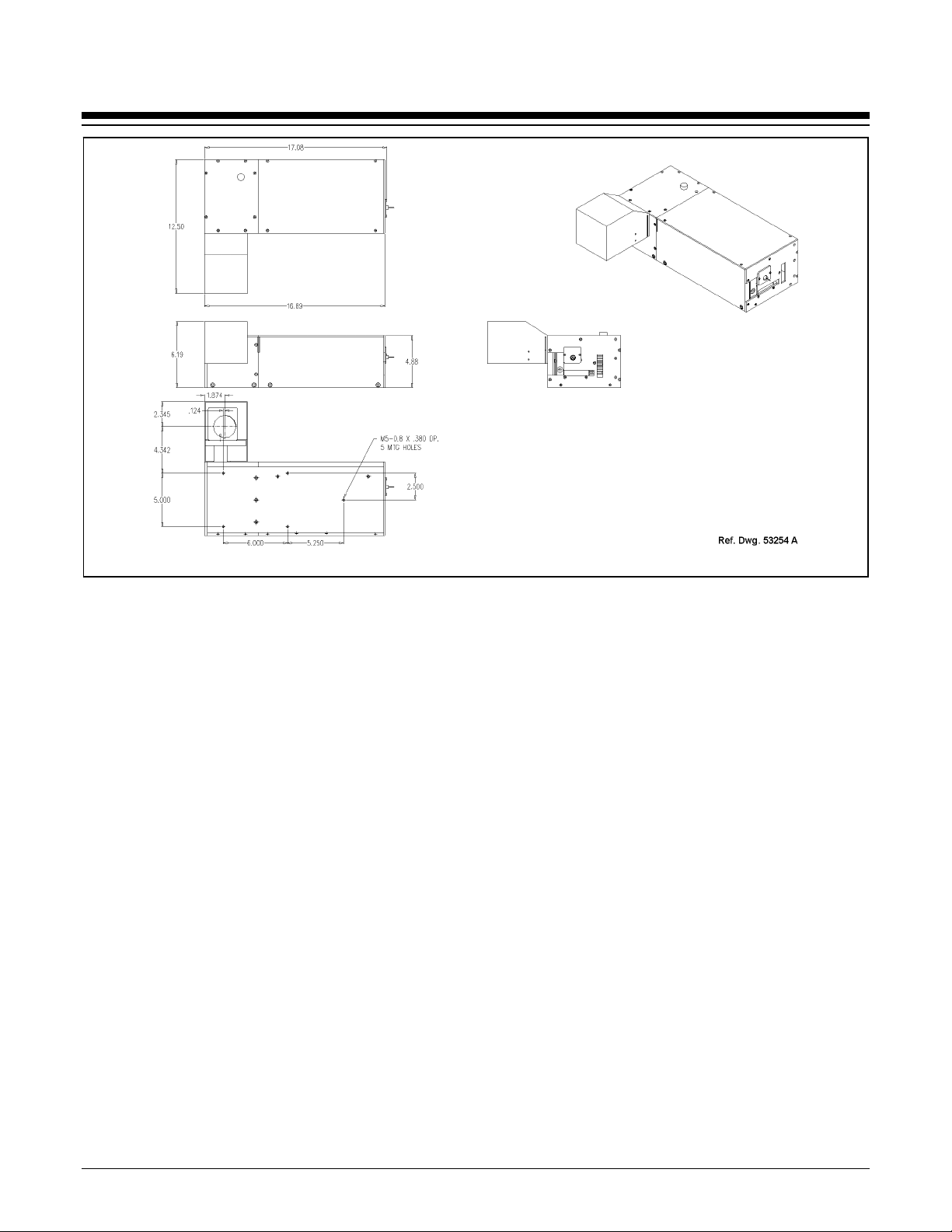
XPRESS™ EP / TLM Laser Marking System
XPRESS EP Laser Marking Head Dimensions and Mounting Details
System Setup
Complete installation procedures are provided in the
XPRESS EP/TLM Installation/Maintenance Manual. The
following procedures are listed for reference only to provide a
general overview of the installation process.
1. Equipment should remain powered down and in OFF
position until mounting is complete.
2. Place computer, monitor, keyboard, and laser controller in
desired location. Locate controller as close as practical to
laser marking head. Standard cable length is 1.75 meters
(5.74 feet) long between the laser marking head and the
laser controller. An optional 4.75-meter (15.58-ft.) fiber
optic cable is also available.
3. Place the laser marking head on selected mounting.
a. Do not bend or kink fiber optic cable. The fiber
optic cable will tolerate approximately 300 mm
(12 in.) diameter bend without damage.
b. Allow a minimum distance of 150 mm (6 in.) at
rear of the laser marking head. This will provide
sufficient room for a proper bend radius of fiber optic
cable.
c. Do not block or obstruct exhaust fan. Note location
of exhaust fan on right side of the laser marking head.
This fan must have adequate clearance to ensure
proper cooling.
4. Mount laser marking head using any three of five factorytapped M5-0.8 mounting holes provided.
a. Locate five pre-drilled M5-0.8 mounting holes. The
one nearest the galvanometer output is referred to as
the "origin". All other mounting hole dimensions are
referenced to this hole. Refer to the Mounting and
Dimension Details drawing more information.
b. Telesis recommends using a minimum of three (3)
attach points for mounting the laser marking head,
one of which should be the origin mounting hole.
c. Mounting bolts must not extend into laser marking
head more than 9.5 mm (.38 in.) to avoid
interference with internal components.
d. The leading edge of customer-supplied mounting
fixture should extend no greater than 25.4 mm (1 in.)
from origin mounting hole to allow clearance for
beam output lens.
e. As viewed from front of the laser marking head in
upright position, center of output beam is 11.0287 cm
(4.342 in.) from origin mounting hole.
5. Secure the laser marking head to mounting fixture using
M5-0.80 bolts and lock washers. Do not over tighten bolts.
6. Ensure laser controller power switch (front panel) is OFF.
7. Select proper fuse arrangement, then connect power cable.
8. Connect fiber-optic cable to laser marking head. Connect
remaining cables, as applicable.
9. Refer to XPRESS EP/TLM Operation Supplement for proper
startup procedure. Refer to laser marking system Operation
Manual for complete information on using system software.
Doc. No. 40213 – 2 of 6
 Loading...