

Page 1
TMP4500E/TMC600 Marking System
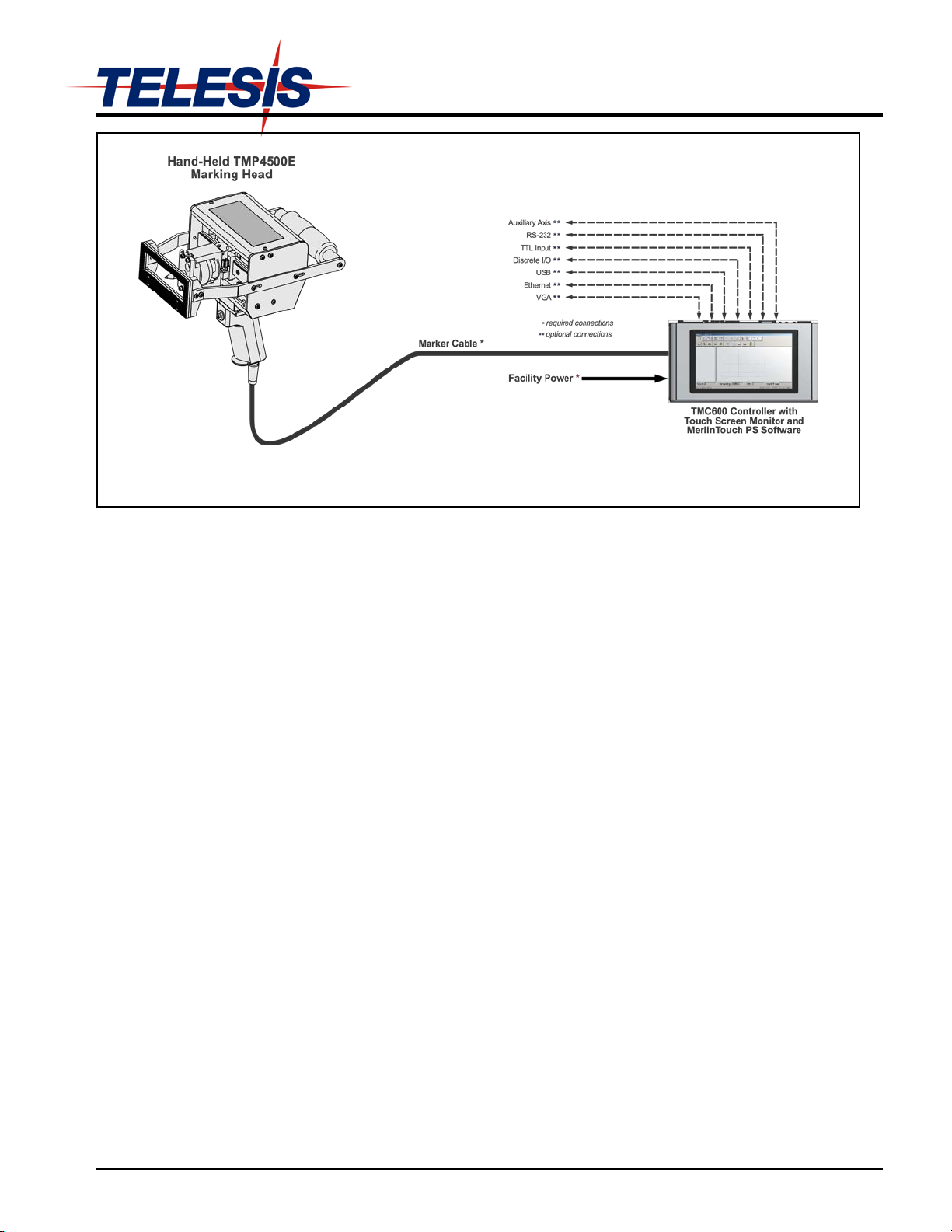
TMP4500E/600 Marking System – G eneral Arrangement
SYSTEM OVERVIEW
The Telesis
messages into a variety of materials such as steel, aluminum, and
plastic. A hardened pin is accelerated to indent dot matrix
characters into the item being marked at depths up to .45 mm
(.018 in.) in mild steel. Character shape, size, dens ity, and locat ion
are determined by the user through the marking system software.
The Marking Head is an electromechanical marker. A metalformed cover houses the internal, mechanical components that
position the pin cartridge. An electric solenoid fires the marking
pin and an internal spring returns the pin to its idle position within
the cartridge. The marking head moves the pin cartridge through
X- and Y-axis rectilinear motions to reach the correct position for
each dot of the characters to be marked. The system software
automatically controls pin extension to mark the message.
The marker uses two stepper-motor drives to rapidly and
accurately position the pin at coordinate-defined locations in the
marking window within .006 mm (.00024 in.). The marker
accommodates the rigorous dynamics of impacting, rebounding,
and rapid positioning of the marking pin through a linear
rail/ball bearing saddle assem b ly, ceramic-coated guide
shaft/linear bushing assemblies, and drive motors with
concentric, linear drive screws.
The lightweight and portable TMP4500E is designed for remote
operation. The hand-held marker incorporates a pistol grip
handle with a Start Print pushbutton switch. A rear-mounted
handle provides additional stability during marking. It can be
used in virtually any orientation.
The integral standoff with its padded front surface is held
against the marking surface while marking. The standoff can be
adjusted forward and aft to change the pin stroke..
The integral standoff with its padded front surface is held
against the marking surface while marking. The standoff can be
adjusted forward and aft to change the pin stroke.
®
TMP4500E marking system permanently prints
A tapped hole is provided in the top of the marking head
(beneath the label) to allow for installation of an eye bolt. The
eyebolt allows the marker to be suspended from a mechanicalassist device such as a cable or cable balancer.
The Pin Cartridge, machined from engineered plastic
materials, offers long life with little maintenance. Screws attach
the pin cartridge to the marking head for easy removal, cleaning,
and pin replacement. The cartridge/solenoid assembly can be
configured for Long Throw or Short Throw operation. Long
Throw configuration allows for deeper marks while Short
Throw configuration allows for faster marking.
The Marking Pins are made of carbide and are available in 30°
and 45° cone angles.
The Marker Cable connects the marker to the controller. The
cable is 4 m (13 ft.) long and is pre-wired to the marking head.
TMC600 Controller runs the MerlinTouch PS software and
provides the user interface for operating the marking system. The
controller features an integrated, 10-in., high-resolution, touch
screen monitor in the top panel. The back panel of the controller
provides the electrical interface for connecting to optional, remote
I/O sources. See TMC600 Controller Specifications for details.
SYSTEM OPTIONS
• Bar Code Scanner
• Bar Code Wand
• Logo/Font Generator Software
• Marking Head Extension Cables
• TMC600 Controller Wall-mounting Bracket Kit
• USB mouse and Keyboard
• Tool Stand (for fixed-mounting applications)
78811A © 2014 Telesis Technologies, Inc. – All Rights Reserved 1 of 9
Page 2
SYSTEM SETUP
The TMC600 is not a sealed unit. Protect it from potentially
The marking head is designed to be used as a hand-held marker.
Optionally, it may be suspended from a cable balancer or mounted
on a Telesis tool stand.
TMP4500E MARKING HEAD
Specifications
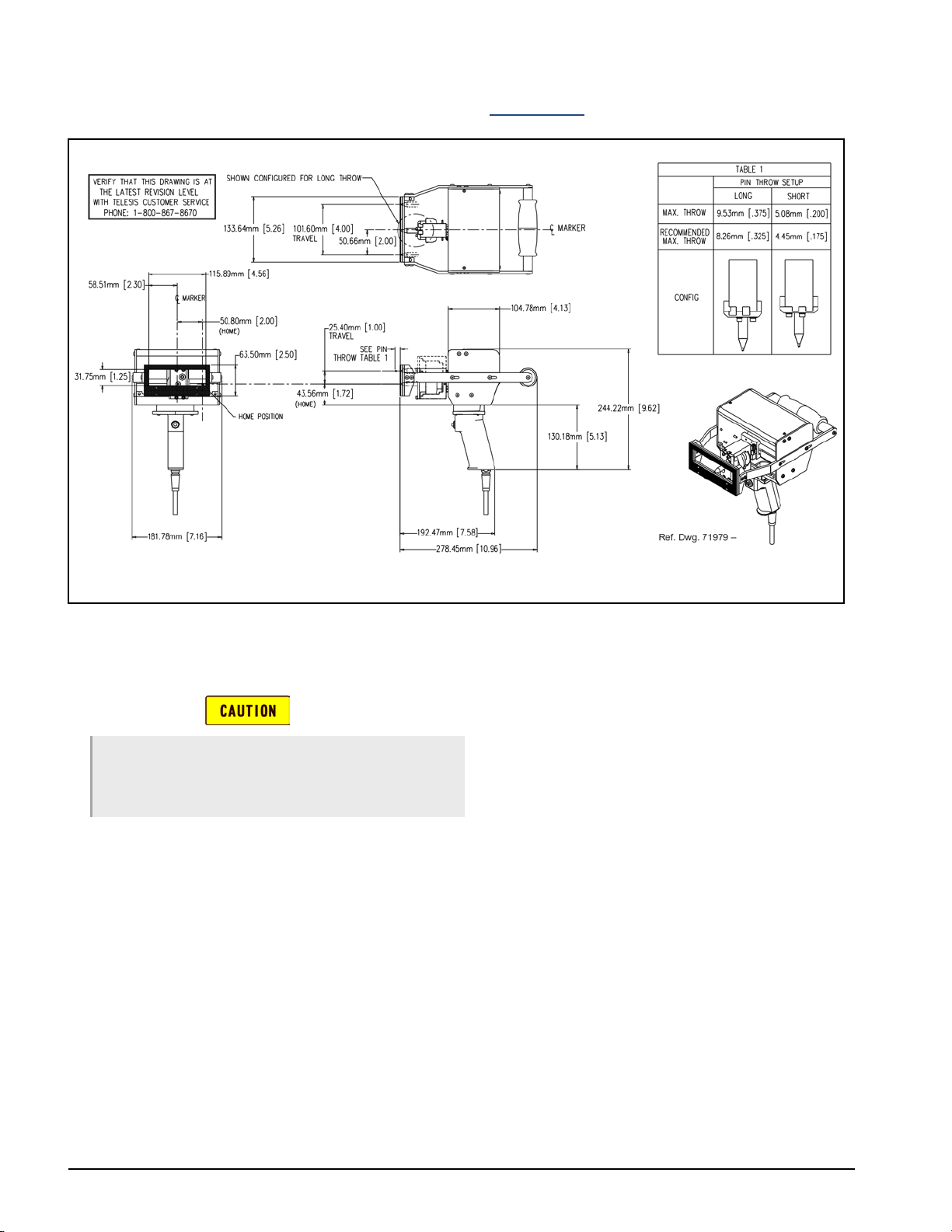
TMP4500E Hand-Held Marking Head Dimensions
The following procedures provide only a general overview of
the installation process. For complete installation instructions,
refer to the TMP4500E Installation & Maintenance Manual and
the TMC600 Controller Installation & Maintenance Manual.
damaging conditions and co ntaminants. Do not block the vents in
case. Ensure the marking system is ele ctrically isolated from any
devices that may generate extreme electromagnetic interference
(EMI).
1. Locate controller as close as practical to marking head.
Standard marker cable length is 4 m (13 ft.).
2. Install the controller as a table-top, wall-mounted, panelmounted, or enclosure-mounted unit, as applicable.
3. Ensure controller power switch is OFF.
4. Connect marker cable to controller.
5. Connect power cable to controller.
6. Position controller power switch to ON (on back panel)
to start the marking system software.
7. Adjust pin stroke for impact depth, as required.
The TMP4500E marking head specifications are subject to
change without prior notice.
Dimensions .............................. see TMP4500E Hand-Held
Rating ...................................... NEMA
Weight ..................................... 3.82 kg (8.4 lb) marker & cable
Noise ........................................ 81.4 dB (max); 73.1 dB (LEQ)
Vibration ................................... Does not exceed 2.5 m/s
Marking Area (W x H) .............. 100 x 25 mm (4.0 x 1.0 in.)
Number of Impact Pins ............ 1
Pin Types ................................. 30° or 45° cone angle
Pin Type ................................... Carbide with
Pin Stroke (max.) ..................... 8.26 mm (.325 in) Long Throw
Operating Temp. ...................... 0° to 50°C (32° to 122° F),
Humidity ................................... 10% to 80%
Marking Head Dimensions
®
1 (I.P. 30)
3.00 kg (6.6 lb) marker only
See Marking Noise for details
See Vibration Data for details
30° or 45° cone angle
4.45 mm (.175 in.) Short Throw
non-condensing
2
2 of 9 78811A
Page 3
TMP4500E/TMC600 Marking System
TMP4500E MARKING HEAD (CONTINUED)
Marking Characteristics
The TMP4500E can produce character sizes from 1.5 to 25 mm
(.060 to 1.0 in.) increments. Characters can be rotated 359° in 1°
increments with a printing resolution range from 4 dots/cm
(10 dots/in.) to 31 dots/cm (80 dots/in.) for an engraved look.
The depth of mark can be adjusted over a significant range by
adjusting the pin stroke and/or adjusting the Depth parameter in
the marking system software.
Marking Speeds
The system can mark 3.175 mm (.125 in.) high characters in the
5x7 font at a rate of 2 characters per second at a depth of .45 mm
(.018 in.) in mild steel. Speeds will vary widely depending on the
selected character size, style, and dot density. Specific tim es can
be verified by a Telesis representative.
Marking Noise
Sound pressure-level tests were conducted on the TMP4500E
Marking System using a Larson-Davis Model 710 sound
pressure meter while dry firing the marker at a 50% duty cycle.
The maximum sound pressure level during the test cycle was
measured at 81.4 dB. The time-weighted average (LEQ) using
the 3 db rule without threshold was 73.1 dB. Typical
applications average a 20% to 30% duty cycle where the timeweighted average would not exceed 69.1 dB(A).
The sound pressure-level tests were carried out under controlled
conditions, imitating as closely as possible, predicted normal
operation. However, noise level is heavily dependent on the part
being impacted. Conditions such as the material being marked,
the rigidity of the work piece, machine settings, ambient noise,
etc., may all vary when in operational use. Such variables will
alter the actual noise level.
Despite detailed guidance provided with each machine, variable
operating conditions are beyond the control of Telesis. The
responsibility of establishing safe working levels of use remains
with the end user. Accordingly, you should conduct your own
sound pressure-level tests for your application while marking
actual work pieces.
Pin Life
Pin life depends largely on the type of material being marked,
how hard or abrasive it is, and the required marking depth.
Vibration Data
Total hand-arm vibration does not exceed 2.5 m/s2.
Vibration tests were performed under controlled conditions
imitating, as closely as possible, typical normal operation.
Conditions such as rigidity of the work piece, material, setting
of the machine, etc. may vary in actual operational use and
would alter the actual vibration level. Despite detailed guidance
instructions provided with each machine, such conditions are
beyond the control of Telesis and must remain the responsibility
of the end user. Accordingly, you should conduct your own tests
to establish safe working levels of use.
The vibration tests were conducted using the following
parameters:
Pin Stroke ................................. 8 mm (.31 in) set for Long Throw
Marking Base ........................... 20 mm (.79 in) thick steel
Marking Surfaces ..................... 3 mm (.125 in) thick steel plate
Marking Mode .......................... Dot
Text Marked ............................. QWERTYUI12345678
5x7 font, 3mm (.12 in) charac ters
The following test results reflect the worst-case scenarios under
the given test conditions.
Pistol Grip Handle
VM T
0.933 m/s2 more than 24 hr more than 24 hr
T
(EAV)
(ELV)
Padded (rear-mounted) Handle
VM T
0.87 m/s2 more than 24 hr more than 24 hr
T
(EAV)
(ELV)
where:
VM = hand/arm Vibration Magnitude.
T
= time to reach the Exposure Action Value based on
(EAV)
continuous marking.
T
= time to reach the Exposure Limit Value based on
(ELV)
continuous marking.
78811A 3 of 9
Page 4
TMC600 CONTROLLER
The TMC600 controller may be installed as a table-top unit,
wall-mounted unit, or panel-mounted unit. All configurations
provide features and connectivity for external communications.
Differences occur only in the mounting configuration.
The TMC600 Controller specifications are subject to change
without prior notice.
Integrated Processor ...... Intel® Dual-Core Atom™
Integrated Monitor .......... 10.1 in., color, 1024 x 600,
capacitive touch screen LCD
Compliance ..................... CE
Rating .............................. NEMA 1 (I.P. 30)
Configurations ................ Table-top or wall-mounted
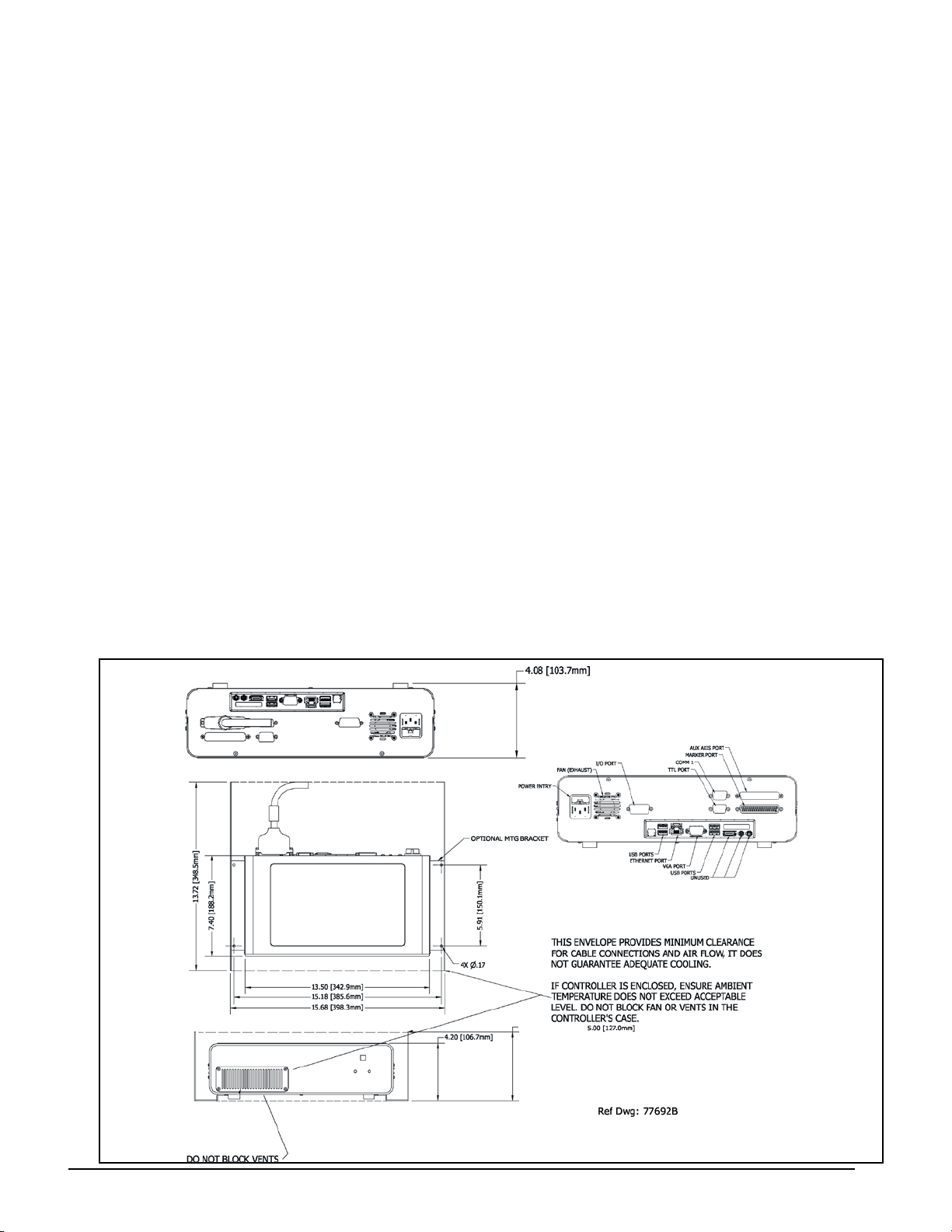
Dimensions ..................... see TMC600 Controller Dimensions
drawing
Weight ............................ 7.00 lb. (3.18 kg) controller only
7.21 lb. (3.28 kg) with wall-mount kit
Operating Temp. ........... 32° to 104° F (0° to 40°C)
Operating Humidity ........ 10% to 80% non-condensing
Power Requirements ..... 115/230 VAC, 3/1.5 amps,
50/60 Hz, single phase
Cooling ............................ Internal, thermostatically controlled fan
Filtering ........................... Integrated, 60 ppi contaminan t filter
Communications ...... RS232, TTL, Discrete I/O, TCP/IP, and
USB (for data backup & transfer)
Input Signals ............. Twelve (12) to tal, opt ically isol ated
8 dedicated, 1 programmable,
3 available
10 VDC minimum voltage
30 VDC maximum voltage
12 to 24 VDC nominal voltage
2.3 mA @ 12VDC nominal current
4.9 mA @ 24VDC nominal current
Output Signals .......... Six (6) total, optically isolated
3 dedicated, 3 available
0.25 amps maximum current
0.50 ohms maximum On resistance
40 VDC maximum line voltage
12 to 24 VDC nominal line voltage
4 of 9 78811A
Page 5
TMP4500E/TMC600 Marking System
TMC600 Controller (continued)
Environmental Considerations
The following environmental considerations must be taken into
account when installing the TMC600 Controller.
Contaminants. The vented TMC600 is rated NEMA 1 (IP30)
and contains a thermostatically-controlled, variable speed fan. It
also incorporates a 60 ppi filter which will filter most common
contaminants. However, in certain environments, the possibility
exists that contaminants can be drawn into the TMC600
controller and possibly result in failure. For that reason, in these
types of environments, the controller must
be located in a sealed
industrial enclosure.
EMI Susceptibility. Although the system has been found to be
in compliance with pertinent susceptibility standards, care
should be taken when installing near welders and other extreme
generators of electromagnetic interference (EMI). Particular care
should be taken to ensure welder currents are not injected
through the marking head chassis. The marking head chassis is
connected to the electrical service earth ground through the
marking head cable. The marking head should be electrically
isolated from all surfaces which could become part of a welder
current path.
System Software
The powerful Telesis MerlinTouch PS software is a Windows
®
based software package that comes installed in the TMC600
controller. It is a graphical user interface that makes pattern
marking and pattern design quick and easy.
The WYSIWYG (what-you-see-is-what-you-get) interface
provides a to-scale image of the pattern as it is created. The
MerlinTouch PS software includes tools to create and edit a
library of pattern files for marking. Each pattern contains one or
more fields; each field defines a single ob ject. Printable objects
may be created to define text strings, arc-text strings, geometric
shapes, graphics, and machine-readable data matrix symbo ls.
Note that for design purposes, Telesis recommends using a
mouse for more precise use of the visual editing capabilities via
the Drag/Drop option.
Printable text fields may include alphanumeric characters,
symbols, and special message flags. Message flags
automatically insert data into the text string, such as serial
numbers, times, dates and user-defined codes. Multiple fields
may be grouped and saved as a block to form a logo. Existing
DXF files can also be imported for marking. Non-printable
fields can be created to clearly display a graphical representation
of the part being marked. Commands may be defined to perform
specific tasks during the marking cycle (e.g., Pause, Go to,
Input, or Output).
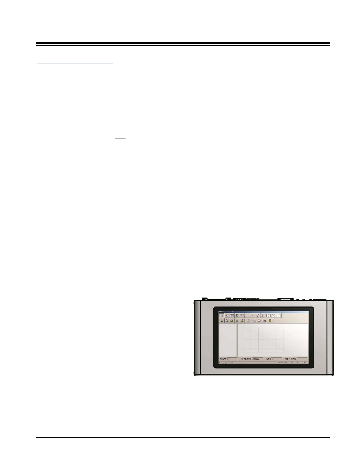
Touch Screen User Interface
The top panel of the controller contains an integrated, 10-in.,
high resolution, touch screen monitor. The monitor displays the
MerlinTouch PS software and provides the user interface for
operating the marking system.
TMC600 Controller with Touch Screen Monitor
and MerlinTouch PS Software
78811A 5 of 9
Page 6

TMC600 CONTROLLER (CONTINUED)
Interface Panel
The back panel of the controller provides various ports for
connecting the marker, host computers, logic controllers,
optional accessories, and remote I/O devices. See below.
RS-232 Interface. The Comm 1 port allows connection to
remote serial devices such as a host computer or a bar code
scanner. See Host Communications for details.
TTL Interface. The TTL Port allows the system to connect
with a simple contact closure circuit such as a remote push
button station or foot pedal switch. These types of devices can
remotely control Start Print and Stop Print operations.
Discrete I/O Interface. The optically-isolated I/O Port allows
you to connect a Programmable Logic Controller (PLC) or
other DC I/O source for remotely controlling marker operations.
See Discrete I/O Controls for details.
USB Interface. The USB ports allow you to connect an
optional mouse and keyboard. You may also connect a memory
stick/flash drive for pattern storage and retrieval and for
performing software upgrades.
Ethernet Interface. The Ethernet Port may be used to connect
a host computer over a local area network (LAN). It allows you
to define the controller as a client or a server socket using
Telesis Extended Protocol. See Host Communications for
details.
VGA Interface. The VGA Port allows you to connect a
separate VGA monitor for troubleshooting, diagnostics, and
testing. Connecting a separate monitor to operate the system is
not recommended since the MerlinTouch PS software is
specifically designed to display on the controller’s integrated,
high-resolution, touch screen monitor.
Discrete I/O Controls
The TMC600 is configured for 12 VDC to 24 VDC I/O only
and is provided to connect a PLC or other DC I/O source. The
optically-isolated I/O Port allows you to remotely select and
load patterns, start printing, stop printing, place the marker
online, and monitor the system output signals. Cable connectors
and connector pins are supplied with the controller for
constructing appropriate interface cables.
Input Signals. These input signals provide the following controls:
INPUT COMM ......... For all inputs (+ or – supply)
START PRINT ......... Begins print cycle
STOP ....................... Stops the print cycle
SEL_0 thru _6 * ....... Remotely selects & loads up to 127*
patterns
SPARE_1, 2, 3 ......... Three (3) spares for use with the Input
command tool or for custom applications
* System software allows SEL_6 signal to be configured for remotely
selecting patterns or for remotely placing the marker online. If used
for marker online, pattern selection is reduced to 63 patterns (max).
Output Signals. These output signals indicate the following states:
OUTPUT COMM ..... For all outputs (+ or – supply)
DONE ...................... Print cycle is complete
READY .................... System ready for message or f or start pr int
command
PAUSED ................. System paused (waiting timeo ut or
command)
SPARE_1, 2, 3 ......... Three (3) spares for use with the Output
command tool or for custom applications
(optional) Auxiliary Axis Interface. The Auxiliary Axis Port
allows the system to connect with two optional motion devices
such as motorized tool posts, rotational drive units. Note that
this port is available only
if the optional Auxiliary Axis Driver
Board is installed in the controller.
6 of 9 78811A
Page 7

TMP4500E/TMC600 Marking System
Host Communications
The marking system software allows you to configure
communication parameters to transmit and receive data to and
from a host computer. To provide maximum integration
flexibility, the system software supports RS-232 serial interfaces
and Ethernet TCP/IP interfaces. The system software also
provides two protocol choices: Programmable Protocol and
Extended Protocol.
RS-232 Interface. The serial (RS-232) communications
interface is most often used with remote devices such as host
computers, terminals, or bar code scanners. The RS-232
interface supports both Telesis Extended Protocol and Telesis
Programmable Protocol.
TCP/IP Interface. The Ethernet (TCP/IP) interface is most
often used with host computers communicating over a local area
network (LAN).
The Port parameter identifies the host computer socket that is
assigned to the marking system. If more than one marking
system is installed in a network configuration, each system must
use a separate and unique port number. The Address parameter
identifies the IP address of the host computer. The marking
system software supports both fixed addressing and dynamic
addressing.
Programmable Protocol. Use this protocol where very simple
one-way communications are required (such as with bar code
scanners). Programmable Protocol provides no error checking or
acknowledgment of the transmitted data. Note that XON/XOFF
Protocol applies even when Programmable Protocol is selected.
Starting Character specifies where the software begins to
count character positions. This number must be entered in
decimal format (e.g., "2" for ASCII Start of Text "STX").
Terminating Character identifies the end of transmitted
string (usually "13" for ASCII carriage return character).
Character Position counted from the starting character
ignoring all characters preceding it.
Character Length accepts variable length messages (if set
to 0) or messages of a pre-specified, fixed number of
characters.
Ignore Character identifies the character to ignore when sent
from the host (usually "10" for ASCII line feed character)).
Message Type allows message-type recognition which
defines how the marking system will use data it receives from
the host.
1 Message type 1 overwrites the first line of the first text
field with data extracted from the ho st
P Message type P loads a specific pattern identif ied by
data extracted from host
Q Message type Q updates the tex t in the first query
buffer with data extra cted from the host
V Message type V updates the first variable text flag
found in the pattern with data extracted from the host
0 Message type 0 (zero) indicates tha t ho st wi ll pro vide
message type, field number ( if app lica ble), line nu mber
(if applicable), and data; delegates message type
selection to the host on message-by-message basis.
The host message must use the format:
Tnn<string>
where:
T = 1, P, Q, or V to indicate message type
nn = two-digit field number or query text
buffer where data will be placed.
Note: Not used with Message Type
P.
<string> = For Message Type P, indicates the
pattern name to be loaded.
For Message Types 1, Q, or V,
indicates the data to be inserted into the
field or the query text buffer, as
applicable.
78811A 7 of 9
Page 8

TMP4500E/TMC600 Marking System
Host Communications (continued)
Extended Protocol. This protocol selection includes error checking and transmission acknowledgment. It should be used in applications
where serial communication is a vital part of the marking operation. All communications are carried out in a parent/child relationship with
the host being the parent. Only the host has the ability to initiate communications. If the host does not receive a response within three
seconds, it should re-transmit its original message. If no response is received after three tries, it should declare the link to be down.
The following describes the Extended Protocol message format as sent from the host to the TMC600 controller
SOH TYPE [##] STX [DATA] ETX BCC CR
Where:
SOH ASCII Start of Header character (001H) . Th e contr oller
ignores all characters recei ved prior to t he SOH.
TYPE A single, printable ASCII character that def ines the
meaning (type) and content of t he me ssage
downloaded from the host, where:
1 Message Type 1 overwrites a specific field in
currently loaded pattern with data supp lied in the
host message. See [DATA] for details.
P Message Type P specifies the pattern name to be
loaded for printing. See [DATA] for details .
Q Message Type Q updates a specif ic que ry buff er
with data supplied in the host message.
See [DATA] for details.
V Message Type V updates the variable text in a
specific text field of the current ly loa ded p attern
with data supplied in the host message.
See [DATA] for details.
O Message Type O resets marker and places it
online
G Message Type G initiates a pr int cyc le to mark the
currently loaded pattern
I Message Type I requests the marker return the
status of standard output and input signals. The
system will return a hexadec imal cod e for the 6
output signals and 12 input signals in the following
format:
OO;III
where:
bit 1 READY 0x01
bit 2 DONE 0x02
bit 3 PAUSED 0x04
bit 4 SPARE_1 0x08
bit 5 SPARE_2 0x10
bit 6 SPARE_3 0x20
bit 1 START 0x001
bit 2 STOP 0x002
bit 3 SEL_0 0x004
bit 4 SEL_1 0x008
bit 5 SEL_2 0x010
bit 6 SEL_3 0x020
bit 7 SEL_6 0x040
bit 8 SEL_4 0x080
bit 9 SEL_5 0x100
bit 10 SPARE_1 0x200
bit 11 SPARE_2 0x400
bit 12 SPARE_3 0x800
Input SEL_6 may be configured to place machine
online (default) or for Remote Pattern Selection.
{##] Optional two-digit ASCII numb er that specifi es the
Station ID of the controller when used in multi-drop network
applications. The Station ID may range from 00-31. Note that “00”
is reserved for applications w here only one co ntrol ler is used. In
such applications, this field may be eliminated and “00” will be
assumed.
STX ASCII Start of Text Chara cter ( 002H).
[DATA] Optional character string that m ay be re quire d for
certain message types (e.g., Ty pe 1, P, Q , and V).
Typically, data is sent in the format:
nn<string>
where:
nn = two-digit field number or query text
buffer where data will be placed.
Note: Not used with Message Type P.
<string> = For Message Type P, indicates the
pattern name to be loaded.
For Message Types 1, Q, or V,
indicates the data to be inserted into the
field or the query text buffer, as
applicable.
ETX ASCII end of text ch aracter (003 H).
BCC Optional Block Check Code that is generated and sent
to improve link reliability by providing fault detection.
The BCC is calculated by taking an eight bit addition of
the TYPE and DATA TEXT character s and tran smittin g
them as a three digit ASCII d ecima l number in the
range from 000 to 255. If the sum is greater than 255,
the most significant bit overflows and is disc arded.
CR ASCII Carriage Retur n Char acter (0 0DH).
78811A © 2014 Telesis Technologies, Inc. – All Rights Reserved 8 of 9
Page 9

TMP4500E/TMC600 Marking System
TRADEMARKS
Telesis, PINSTAMP, and Merlin are registered trademarks of Telesis Technologies, Inc. in the United States.
Atom is a trademark of Intel Corporation in the United States and other countries.
Intel is a registered trademark of Intel Corporation in the United States and other countries.
MicroPin is a trademark of Telesis Technologies, Inc. in the United States.
NEMA is the registered trademark and service mark of the National Electrical Manufacturers Association.
Windows and Vista are registered trademarks of Microsoft Corporation in the United States and other countries.
78811A 9 of 9
 Loading...