

Page 1
BenchMark
®
200/BM470 Marking System
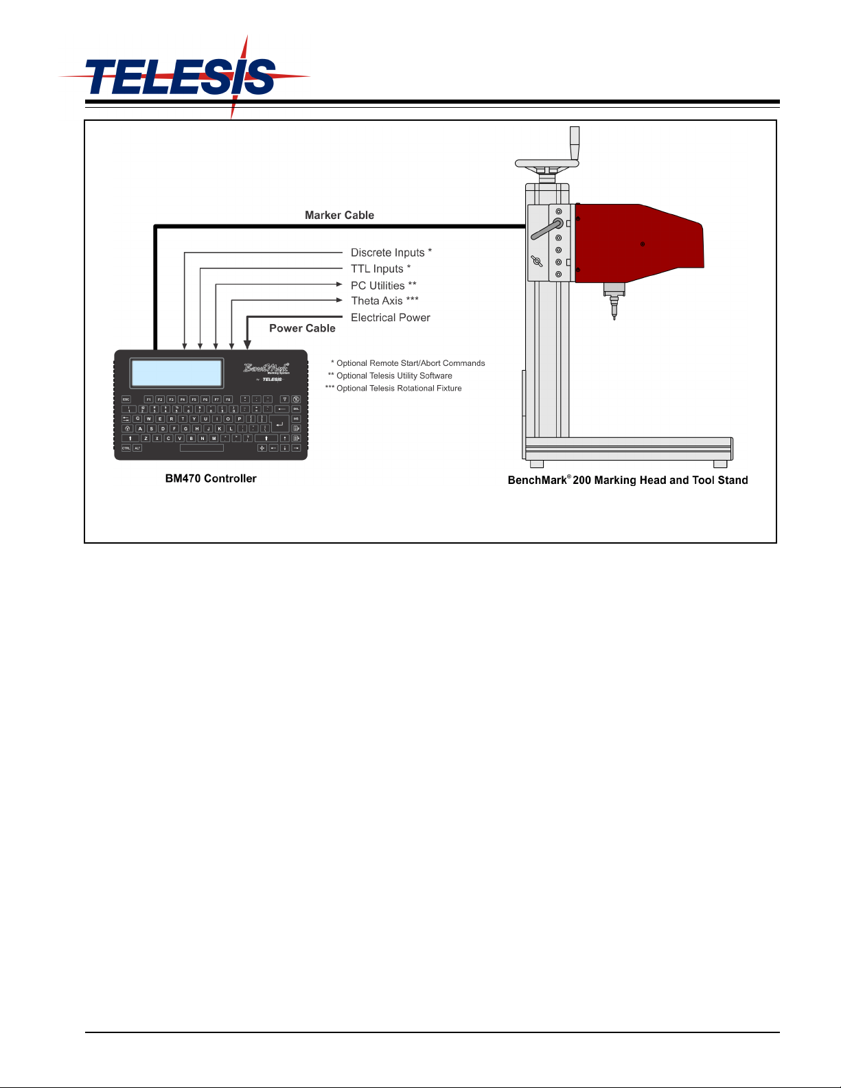
BenchMark200/BM470 Marking S ystem – General Arrangement
SYSTEM OVERVIEW
®
The Telesis
BenchMark®200 marking system permanently prints
messages into a variety of materials such as steel, aluminum, and
plastic. An electric solenoid accelerates a hardened pin to indent
dot matrix characters into the item being marked. Character shape,
size, density, and location are determined by the user through the
marking system software.
The BenchMark200 Marking Head is an electromechanical
marker. A thermo-formed cover houses the internal, mechanical
components that position the pin cartridge and fire the marking
pin. A spring returns the pin to its idle position within the
cartridge. The marking head moves the pin cartridge through Xand Y-axis motions to reach the correct position for each dot of
the characters to be marked. The s ystem software automatically
controls pin extension to mark the message.
The marker uses two stepper-motor drives to rapidly and
accurately position the pin at coordinate-defined locations in the
marking window within 0.032 mm (0.00125 in.). The marker
accommodates the rigorous dynamics of impacting, rebounding,
and rapid positioning of the marking pin through a system of rigid
rails and ball bearing saddles, timing belts, and direct-drive,
toothed pulleys.
The pin design permits high quality, consistent marks on irregular,
slightly curved surfaces. It also accommodates applications where
marking surfaces cannot be positioned at a consistent distance
from the marker.
The Marker Cable connects the marker to the BM470 Controller.
The cable is 4 m (13 ft.) long and is pre-wired to the marking
head.
The Pin Cartridge, machined from engineered plastic materials,
offers long life with little maintenance. Screws attach the pin
cartridge to the marking head for easy removal, cleaning, and pin
replacement.
The 25XLE-series Marking Pins are made of tungsten carbide
and are available in 30° and 45° cone angles.
BM470 Controller contains an integrated keyboard with an LCD
display. It provides a text-only operator interface and allows full
operational control of the marking head. The back panel provides
an electrical interface for connecting optional, remote I/O sources.
Refer to BM470 Controller Specifications for details.
The Tool Stand holds the marking head and provides a base for
securing parts to be marked. It uses a screw jack with an
adjustment wheel to position the marker above the marking
surface. Adjustment locks secure it in place. The generous
vertical adjustment accommodates parts up to 298.4 mm
(11.75 in.) high. The tool stand base contains slots to
accommodate part fixtures. The tool stand comes with two 8mm
T-nuts to aid in securing the parts for marking..
34743A © 2011 –2012 Telesis Technologies, Inc. – All Rights Reserved 1 of 8
Page 2
BenchMark®200/BM470 Marking System
SYSTEM OPTIONS
• Tool Stand Assembly
• Marking Head Extension Cables
• Auxiliary Axis Driver Board Kit
• Motorized Theta-axis with Programmable Rotary Drive Unit
• BM470 Controller Wall-mounting Bracket Kit
• Bar Code Scanner or Bar Code Wand with Cable
• Foot Switch (Start Print) or Pushbutton Station (Start/Abort)
• Backup Utility Software
• Upgrade Utility Software
• Logo/Font Generator Software
• BM470+ Enhanced Communications Software
SYSTEM SETUP
1. Position tool stand assembly in desired location.
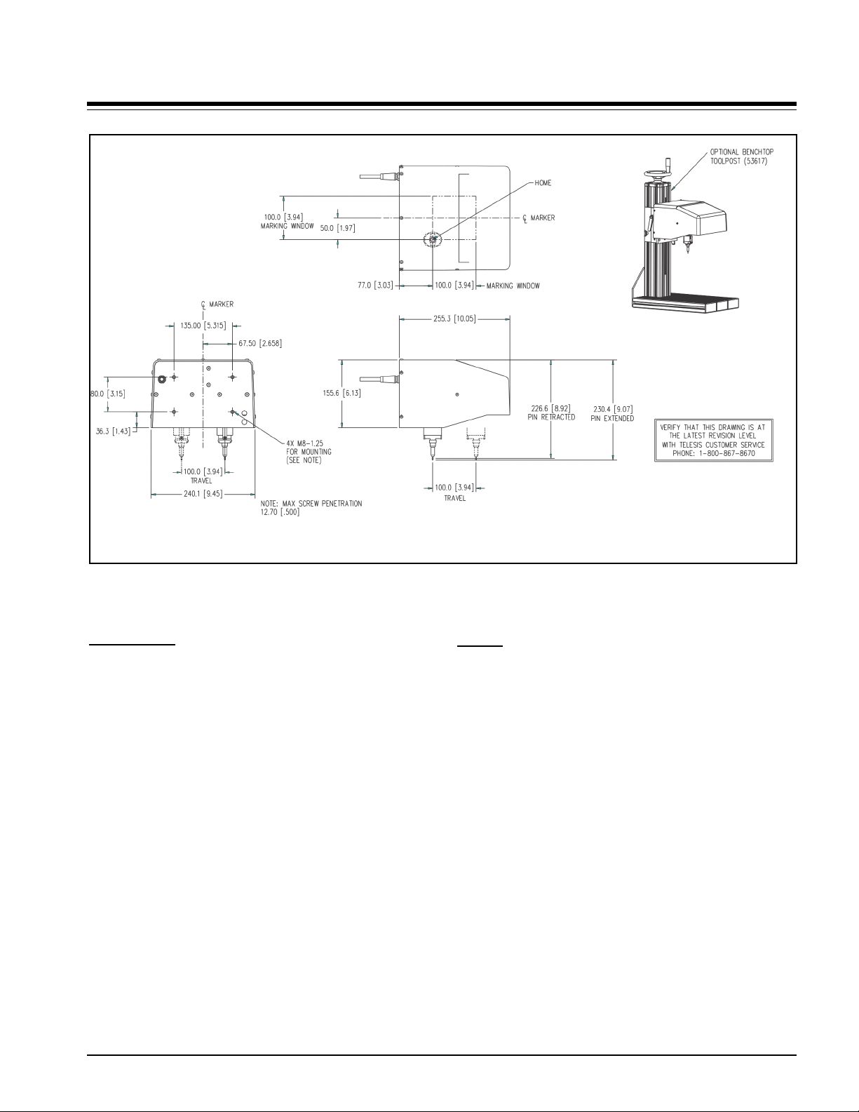
2. Mount marking head to the tool stand assembly using four
M8-1.25 socket head cap screws. Screws must extend int o
the back plate at least 9mm (0.375 in.) but not more
than 12mm (0.5 in.). Refer to the Benchmark200 Marking
Head Dimensions drawing (above) for details.
CAUTION
The BM470 Controlle r is not a sealed unit. Protect it from
potentially damaging conditions and contaminants. Do not
block vents in bottom of case. Ensure the marking system
is electrically isolated from any devices that may generate
extreme electromagnetic interference (EMI).
3. Locate controller as close as practical to marking head.
Standard marker cable length is 4 m (13 ft.).
4. Ensure controller power switch (on back panel) is OFF;
connect power cable to controller.
5. Connect marker cable from marking head to controller;
tighten securely.
6. Position controller power switch to ON (on back panel) to
start the marking system software.
7. Adjust pin stroke for proper pin impact depth.
BENCHMARK200 MARKING HEAD
Specifications
The BenchMark200 marking head specifications are subject to
change without prior notice.
Dimensions ....................... see BenchMark200 Marking Head
Dimensions drawing for details.
Weight .............................. 5.63 Kg (12.375 lb.) marker & cable
5.08 Kg (11.185 lb.) marker only
Noise ................................. 70.9 dB (max); 61.8 dB (LEQ)
See Marking Noise for details
Operating Temperature. ... 0° to 50° C (32° to 122° F),
non-condensing
Marking Area .................... 100 x 100 mm (4.0 x 4.0 in.)
Pin Types .......................... 25XLE-series
Pin Material ....................... Tungsten Carbide
Marking Characteristics
The BenchMark200 can accommodate character sizes from
.762 to 100 mm (.030 to 4.0 in.) in .025 mm (.001 in.) increments.
Characters can be rotated in 1° increments with printing
resolutions from 5 dots/cm (10 dots/in.) to 75 dots/cm
(200 dots/in.) for an engraved look.
Marking Speeds
Generally, the system will mark three characters per second using
5x7 font, 3 mm (.118 in.) high, 2mm (.080 in.) wide characters.
Speeds will vary slightly depending on the selected character size,
style, and dot density. Specific times can be verified by a Telesis
representative.
Marking Depth
The BenchMark200 can obtain a marking depth of .127 mm
(.005 in.) in mild steel (Rb53) using a 25XLE carbide pin with a
45° cone angle. The depth of mark can be adjusted over a
significant range by changing the impact force (via software
parameter) or by changing the impact distance (pin stroke).
Specific depths can be verified by a Telesis representative.
continued...
2 of 8 34743A
Page 3
BenchMark®200/BM470 Marking System
BenchMark200 Marking Head Dimensions
BENCHMARK200 MARKING HEAD (continued) Marking Noise
Sound pressure-level tests were conducted on the BenchMark200
Marking System using a Larson-Davis Model 710 sound pressure
meter while dry firing the marker at a 50% duty cycle. The
maximum sound pressure level during the test cycle was measured
at 70.9 dB. The time-weighted average (LEQ) using the 3 db rule
without threshold was 61.8 dB. Typical applications average a
20% to 30% duty cycle where the time-weighted average would
not exceed 70 dB(A).
The sound pressure-level tests were carried out under controlled
conditions, imitating as closely as possible, predicted normal
operation. However, noise level is heavily dependent on the part
being impacted. Conditions such as the material being marked, the
rigidity of the work piece, machine settings, ambient noise, etc.,
may all vary when in operational use. Such variables will alter the
actual noise level.
Despite detailed guidance provided with each machine, variable
operating conditions are beyond the control of Telesis. The
responsibility of establishing safe working levels of use remains
with the end user. Accordingly, you should conduct your own
sound pressure-level tests for your application while marking
actual work pieces.
Pin Life
Pin life depends largely on the type of material being marked, how
hard or abrasive it is, and the required marking depth. On typical
metals with a hardness of Rockwell Rb47, marking at a depth of
.127 mm (.005 in.), carbide pins average approximately 9 million
impressions before needing sharpened.
34743A 3 of 8
Page 4

BenchMark®200/BM470 Marking System
BENCHMARK TOOL STAND
Specifications
The BenchMark Tool Stand specifications are subject to change
without prior notice.
Dimensions (H x W x D) .......... 686.0 x 270.0 x 414.0 mm
Height Adjustment ................... 298.4 mm (11.75 in .)
Weight ...................................... 13.9 Kg. ( 30.5 lb.)
Additional Features ............... see BenchMark Tool Stand
(27.0 x 10.63 x 16.29 in.)
with standard 25XLE pin/cartr idge
Dimensions drawing for details.
BenchMark Tool Stand Dimensions
4 of 8 34743A
Page 5

BenchMark®200/BM470 Marking System
BM470 CONTROLLER
Specifications
The BM470 Controller specifications are subject to change
without prior notice.
Compliance ........................... CE, RoHS
Rating ................................... NEMA 1 (I.P. 30)
Mounting Configuration ......... Table-top
Dimensions ............................... see BM470 Controller Dimensions
drawing for details
Weight .................................. 1.68 Kg (3.69 lb.) controller only
Power Requirements ............ 95 to 250 VAC, 2 amps, 50-60 Hz,
single phase
Operating Temperature ........ 0° to 50°C (32° to 122° F),
non-condensing
Operating Humidity ............... 10% to 80% non-condensing
Cooling ..................................... Internal, thermostatically-controlled fan
Communications ................... TTL, RS232, and USB *
Input Signals ** ........................ Two available (Start Print, Stop/Abor t)
10 VDC (minimum voltage)
30 VDC (maximum voltage)
12 to 24 VDC (nominal voltage)
2.3 mA @ 12VDC; 4.9 mA @
24VDC (nominal current)
** USB for data backup & transfer
** Additional I/O signals available with the optional
BM470+ Enhanced Communications Software
BM470 Controller Dimensions
34743A 5 of 8
Page 6

BenchMark®200/BM470 Marking System
BM470 CONTROLLER (continued) Environmental Considerations
The following environmental considerations must be taken into
account when installing the BM470 controller.
Contaminants. The vented and fan-cooled controller is rated
NEMA 1 (IP30). Accordingly, in environments where solid
and/or liquid contaminants are present, the possibility exists
that these contaminants can be drawn into the controller and
possibly result in failure of a number of electronic components.
For that reason, in these types of environments, the controller
must be located in a sealed industrial enclosure.
EMI Susceptibility. Although the system has been found to be
in compliance with pertinent susceptibility standards, care
should be taken when installing near welders and other extreme
generators of electromagnetic interference (EMI). Particular
care should be taken to ensure welder currents are not injected
through the marking head chassis. The marking head chassis is
connected to the electrical service earth ground through the
marking head cable. The marking head should be electrically
isolated from all surfaces which could become part of a welder
current path.
Interface Panel
The back panel of the controller provides various ports for
connecting the marker and optional accessories. See below.
System Software
The system software is permanently installed i n the controller. It
provides the user interface for the operator to co n t rol the marker.
The software also provides a library for storing, loading, and
editing user-defined patterns.
Patterns are files stored in the contro ller ’ s memory. Depending on
the size of the pattern files, the cont ro l ler can s tore up to 200
patterns. Each pattern contains one or mo r e f ield s; each field
defines a single object.
Printable objects may be created to define tex t strings, arc-text
strings, geometric shapes , graphics, and machine-readable data
matrix symbols. Printable text fields may inclu d e alphanumeric
characters, symbols, and special message flags. Message flags
automatically insert data into the text string, such as serial
numbers, times, dates and user-defined codes.
Non-printable objects may be defined to specify commands for the
marker to execute (e.g., Go To, Print, Sto p ) .
Marker Port. The Marker port connects the BenchMark200
marking head to the BM470 Controller. It supplies the marking
head with electrical power and provides input/output signals to
and from the controller for marker operation
TTL Port is configured for VDC input only. It allows the system
to connect with a simple contact closure circuit such as a remote
push button station or foot pedal switch. These types of devices
can remotely control Start Print and Stop (Abort) Print operations.
Comm Port allows connection to a remote serial device. The
Comm port may be used to connect an optional, customersupplied PC to access Telesis software utilities. Utility software
may be used to backup patterns stored in the controller, to
download a custom font to the controller, or to download
controller software upgrades. The Comm port also allows you to
connect an optional bar code scanner. The software reads the
scanned input and inserts the data into a variable text field within
the currently loaded pattern.
USB Port allows you to connect a memory stick/flash drive for
pattern storage/retrieval and for software upgrades.
(optional) Auxiliary Axis Port is available only if the controller is
configured with the optional auxiliary-axis circuit card. This
configuration allows connection to a rotational drive unit to make use
of the software’s Theta-axis features.
6 of 8 34743A
Page 7

BenchMark®200/BM470 Marking System
BM470+ ENHANCED COMMUNICATIONS SOFTWARE
The optional BM470+ Enhanced Communications software allows
you to expand the controller’s communication capability. It makes
full use of the I/O Port available and allows you to configure the
Comm Port communication parameters. See I/O Control Signals and
Host Communications (below) for more information.
I/O Control Signals
Additional input and output signals are available through the I/O
Port only if the system uses the optional BM470+ Enhanced
Communications software. The I/O Port is configured for 12 to 24
VDC I/O only and may be used to connect a PLC or other DC I/O
source. The optically-isolated I/O Port allows you to remotely
select and load patterns, start printing, stop printing, place the
marker online, and monitor the system output signals. Cable
connectors and connector pins are supplied with the controller for
constructing appropriate interface cables.
Input Signals. These input signals provide the following controls:
INPUT COMM ................... For all inputs (+ or – supply)
START PRINT .................. Begins print cycle
STOP ............................... Stops the print cycle
SEL_0 thru _6 * ................. Remotely selects & loads up to
SPARE_1, 2, 3 .................. Three (3) spares for custom
System software allows SEL_6 signal to be configured for remotely
*
selecting patterns or for remotely placing the marker online. If used for
marker online, pattern selection is reduced to 63 patterns (max).
127* pattern files
applications
Output Signals. These output signals indicate the following
states:
OUTPUT COMM ............... For all outputs (+ or – supply)
DONE ............................... Print cycle is complete
READY ............................. System ready for message or for start
PAUSED .......................... System paused (waiting timeout or
NO FAULT ....................... System status (normal or fault
SPARE_1, 2 ...................... Two (2) spares for custom
print command
command)
detected)
applications
Host Communications
The BM470+ Enhanced Communications software allows you to
configure the RS-232 parameters for the Comm Port.
The serial interface is most often used to connect a host computer,
a data terminal, or a bar code scanner. The following describes the
serial data character format for all transmissions to and from the
BM470 Controller.
• Asynchronous
• 1200, 2400, 4800, 9600, 19200, 38400, or 115200 Baud
• 1 or 2 Stop Bits
• 7 or 8 Data Bits
• None, Even or Odd Parity
Host Communications (continued)
In addition defining Comm Port communication parameters, you
can select the type of protocol to be used: Extended Protocol or
Programmable Protocol.
Programmable Protocol. Use this protocol where very simple
one-way communications are required (such as with bar code
scanners). Programmable Protocol provides no error checking or
acknowledgment of the transmitted data. Note that XON/XOFF
Protocol applies even when Programmable Protocol is selected.
Starting Character specifies where the software begins to
count character positions. This number must be entered in
decimal format (e.g., “2” for ASCII Start of Text “STX”).
Terminating Character identifies the end of transmitted string
(usually “13” for ASCII carriage return character).
Character Position counted from the starting character
ignoring all characters preceding it.
Character Length accepts variable length messages (if set
to 0) or messages of a pre-specified, fixed number of characters.
Ignore Character identifies the character to ignore when sent
from the host (usually “10” for ASCII line feed character)).
Message Type allows message-type recognition which defines
how the marking system will use data it receives from the host.
1 Message type 1 overwrites the first line of the first text
field with data extracted from the host
P Message type P loads a specific pattern identified by
data extracted from host
Q Message type Q updates the text in the first query
buffer with data extracted from the host
V Message type V updates the first variable text flag
found in the pattern with data extracted from the host
0 Message type 0 (zero) indicates that host will provide
message type, field number (if applicable), line number
(if applicable), and data; delegates message type
selection to the host on message-by-message basis.
The host message must use the format:
Tnn<string>
where:
T = 1, P, Q, or V to indicate message type
nn = two-digit field number or query text buffer
where data will be placed.
Note: Not used with Message Type P.
<string> = For Message Type P, indicates the pattern
name to be loaded.
For Message Types 1, Q, or V, indicates
the data to be inserted into the field or the
query text buffer, as applicable.
34743A 7 of 8
Page 8

BenchMark®200/BM470 Marking System
BM470+ ENHANCED COMMUNICATIONS (continued)
Host Communications (continued)
Extended Protocol. This protocol selection includes error checking and transmission acknowledgment. It should be used in applications
where serial communication is a vital part of the marking operation. All communications are carried out in a parent/child relationship with the
host being the parent. Only the host has the ability to initiate communications. If the host does not receive a response within three seconds, it
should re-transmit its original message. If no response is received after three tries, it should declare the link to be down.
The following describes the Extended Protocol message format as
sent from the host to the BM470 controller.
SOH TYPE [##] STX [DATA] ETX BCC CR
where:
SOH ASCII Start of Header character (00 1H). Th e co ntroller
ignores all characters recei ved prior to t he SOH.
TYPE A single, printable ASCII character that def ines the
meaning (type) and content of t he me ssage d ownloa ded
from the host, where:
1 Message Type 1 overwrites a specific field in
currently loaded pattern with data supp lied in the
host message. See [DATA] for details.
P Message Type P specifies the pattern name to be
loaded for printing. See [DATA] for details .
Q Message Ty pe Q updates a spec ific query buffer
with data supplied in the host message.
See [DATA] for details.
V Message Type V updates the variable text in a
specific text field of the current ly loa ded p attern wit h
data supplied in the host message.
See [DATA] for details.
O Message T ype O resets marker and places it online
G Message T ype G ini tiates a pr int cyc le to mark the
currently loaded pattern
I Message Type I requests the marker retur n the
status of standard output and input signals. The
system will return a hexadec imal cod e for the 6
output signals and 12 input signals in the following
format:
OO;III
where:
bit 1 READY 0x01
bit 2 DONE 0x02
bit 3 PAUSED 0x04
bit 4 NO_FAULT 0x08
bit 5 SPARE_1 0x10
bit 6 SPARE_2 0x20
bit 1 START 0x001
bit 2 STOP 0x002
bit 3 SEL_0 0x004
bit 4 SEL_1 0x008
bit 5 SEL_2 0x010
bit 6 SEL_3 0x020
bit 7 SEL_6 * 0x040
bit 8 SEL_4 0x080
bit 9 SEL_5 0x100
bit 10 SPARE_1 0x200
bit 11 SPARE_2 0x400
bit 12 SPARE_3 0x800
Note: Input SEL_6 may be configured
to place machine online (default)
or for Remote Pattern Selection.
[##] Optional two-digit ASCII number that specifies the Station
ID of the controller when used in multi-dr op networ k
applications. The Station ID may range from 00-31. Note
that “00” is reserved for appl icat ions w here o nly one
controller is used. In such applications, th is field may be
eliminated and “00” will be assumed.
STX ASCII Start of Text Character (002H).
[DATA] Optional character string that may be required for c ertain
message types (e.g., Type 1, P, Q, and V).
Typically, data is sent in the format:
nn<string>.
where:
nn = two-digit field number or query text buffer
where data will be placed.
Note: Not used with Message Type P.
<string> = For Message Type P, indicates the pattern
name to be loaded.
For Message Types 1, Q, or V, indicates
the data to be inserted into the field or the
query text buffer, as applicable.
ETX ASCII end of text ch aracter (003 H).
BCC Optional Block Check Code th at is gener ated and sent to
improve link reliability by providing fault detection. The
BCC is calculated by taking an eight bit addition of the
TYPE and DATA TEXT characters and tr an smitting them
as a three digit ASCII decimal number in the range from
000 to 255. If the sum is grea ter t han 25 5, t he mo st
significant bit overflows and is discarded .
CR ASCII Carriage Return Character (00DH) .
TRADEMARKS
Telesis and BenchMark are registered trademarks of
Telesis Technologies, Inc. in the United States.
8 of 8 34743A
 Loading...