

Page 1
1
DV8 Prompting System Setup Instructions
(monitors in this document may not reflect the monitor you receive)
Page 2
2
Table of Contents
1) Parts and accessory list… ……………………………page 3
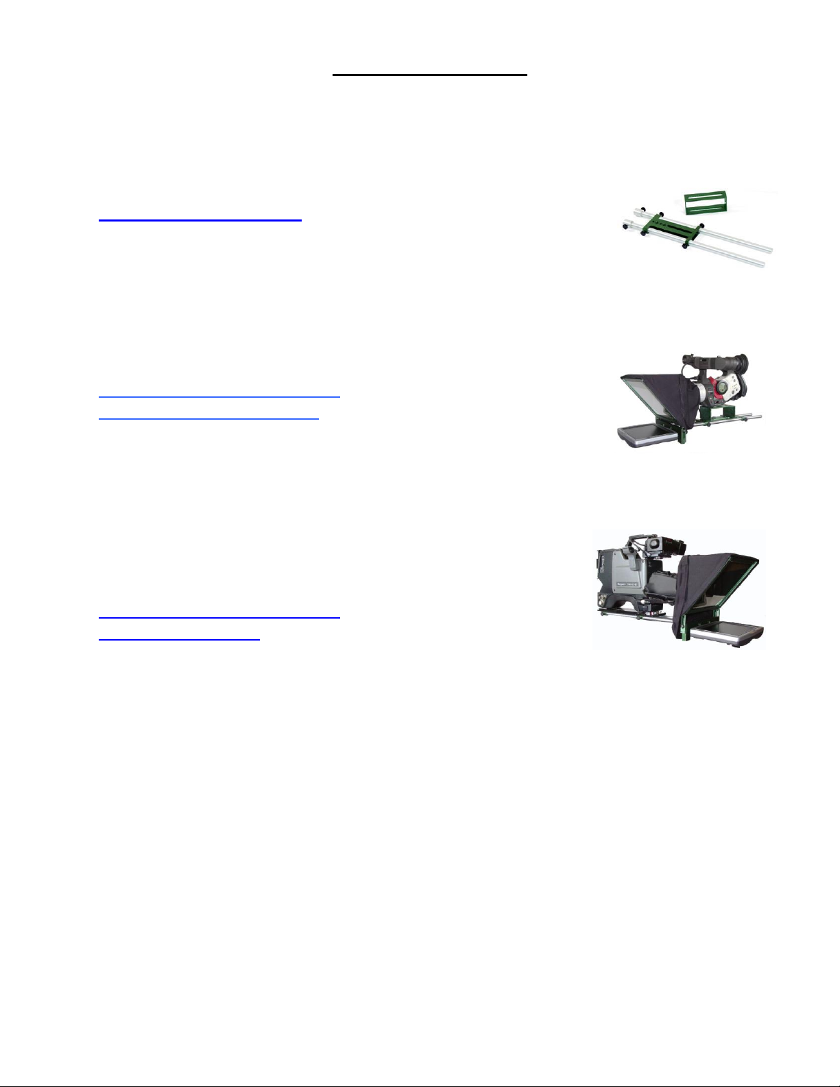
2) Mounting Configuration #1 –
DV Camera Configuration ……………………………page 4
3) Mounting Configuration #2 –
ENG Configuration …………………………………...page 7
Page 3
3
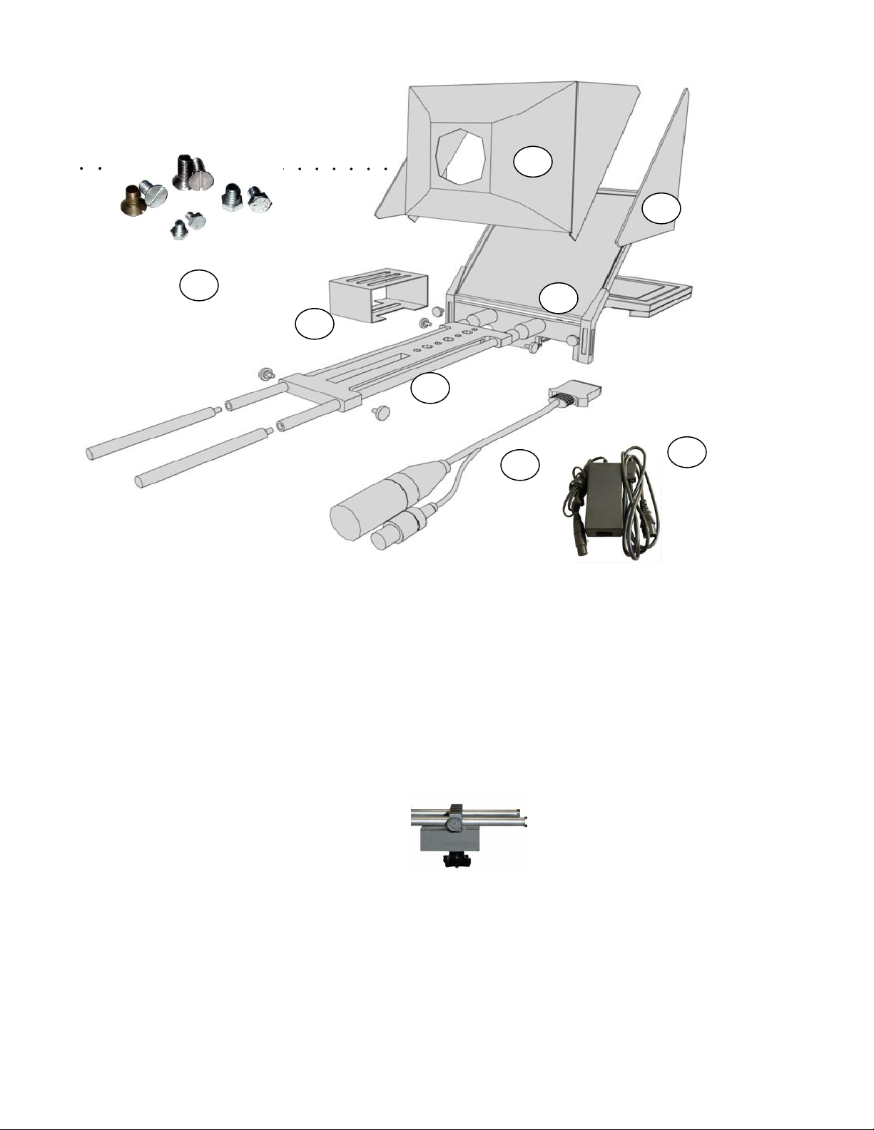
1 234578
6
Parts:
1) Telescript GlidePlate
2) 2” Riser for DV cameras
3) 8” Flat panel monitor and folding Lensview assembly
4) Folding hood and conical mask
5) Removable side panels
6) Mounting hardware screws and washers
7) Power and video input cable harness
8) Power supply
Counter Balance Weight
Page 4
4
DV Camera Configuration
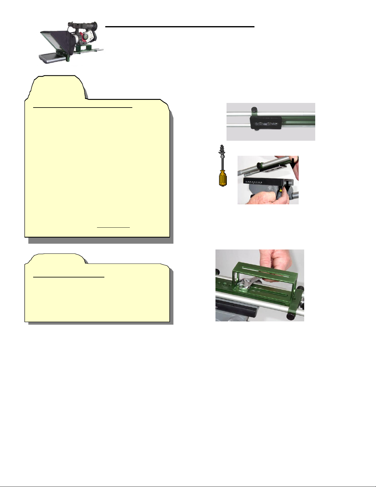
Figure 1
Figure 2
WARNING : Use only video heads and tripods with enough load capacity to support the total weight of
the camera/teleprompter system (camera, camera accessories, teleprompter mount, counter balance
weight, riser, batteries, etc.). Use of under rated tripod and video head support may result in collapse
and sever damage to equipment.
Step 1
Attach the GlidePlate to the tripod
Option 1)
If the tripod has a wedge plate remove it from the
tripod. Position the wedge plate over the
threaded holes on the bottom* of the GlidePlate.
Using the screws provided with the wedge plate
and a flat head screwdriver attach the wedge
plate to the GlidePlate.
Secure the configured GlidePlate to the tripod
and LOCK the video head.
Option 2)
If the tripod has just an attachment screw position
the appropriate threaded hole in the bottom* of
the GlidePlate over the attachment screw and
secure.
*bottom = side with the beveled slot
(Figure 1)
Step 2
Attach the Camera Riser
Position the 2” riser over the threaded holes in the
top of the GlidePlate. Secure the riser in place
with two washers and bolts.
Hint: Don’t tighten all the way to allow for easy
adjustment.
(Figure 2)
Page 5
5
Figure 3
HINT: If the reflective (correct) side of the BeamSplitter
is not marked (black dot in one of the corners) it can be
identified using a pointed object like a pencil or a key. With
the glass at an angle (about 45 degrees), hold the pointed
object as close to the BeamSplitter surface as possible
without touching it. If the image is sharp and clear then it
Figure 4
Figure 5
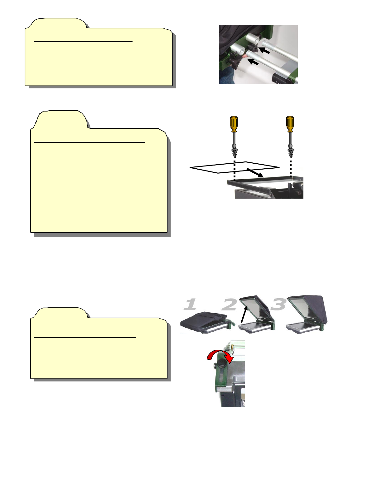
Step 3
Attach the monitor and LensView
Leave LensView folded down. Loosen the
thumbscrews on the monitor/LensView assembly
collars. Slide collars onto the GlidePlate rods
and secure with thumbscrews.
(Figure 3)
Step 4
Insert the BeamSplitter into the frame
If beamsplitter is already in place skip to
Step 5. If the folding hood is velcroed to the
top portion of the frame, remove it.
Completely remove the 2 slotted screws on the
inside of the top of the frame. Remove the
top of the frame. Position the beamsplitter
with the correct side facing down and slide it
forward and down the channel (under any
protruding screws) until it rests on the bottom
of the frame. Replace the top of the frame and
secure with 2 slotted screws.
(Figure 4)
Step 5
Rotate beamsplitter frame in place
Push up on the top of the folding frame to
rotate into place. Secure by inserting two
thumbscrews and turning until tight.
(Figure 5)
Page 6
6
Figure 6
Figure 7
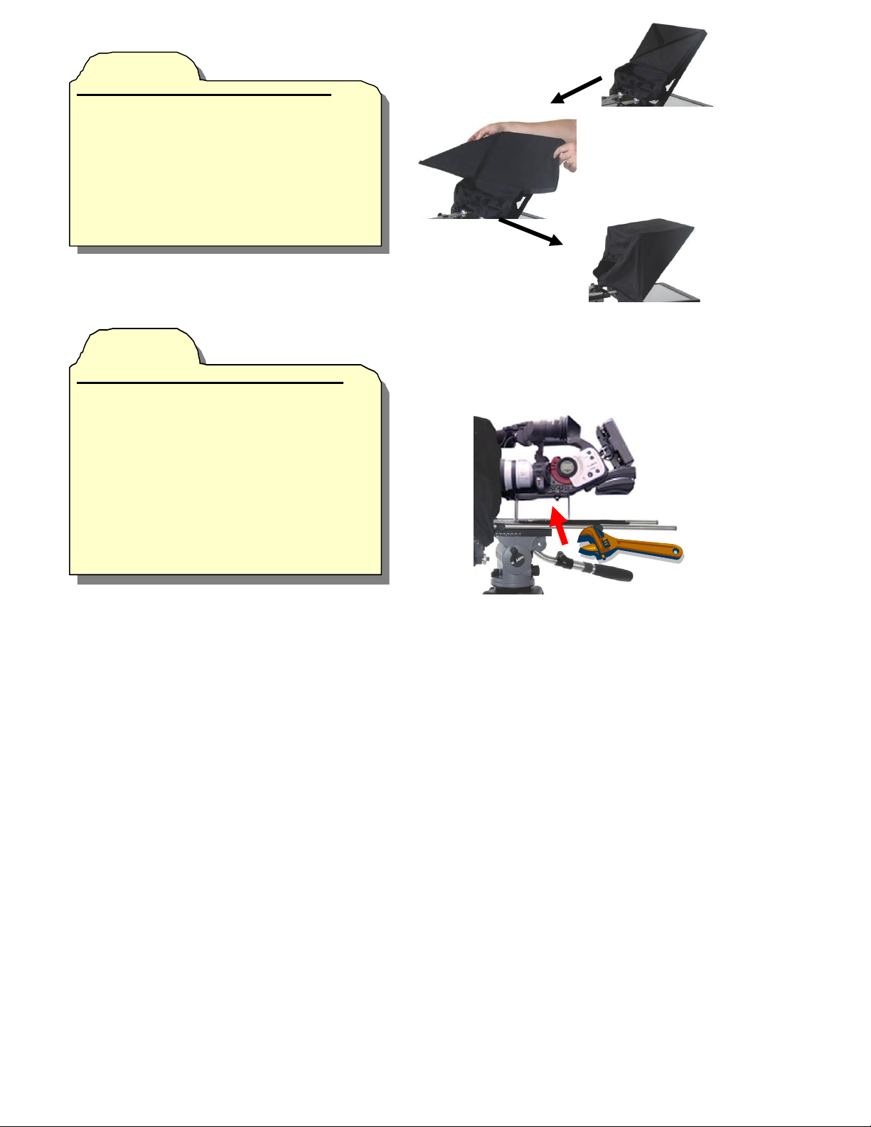
Step 6
Attach and unfold the hood and mask
Unfold the “wings” and simultaniously
press up so the velcro on the wings meets
the velcro on the sides of the frame.
Secure by lightly pressing along the edge
of the hood and frame. With the hood in place
position the mask and secure it to the hood
using the velcro in the outside of the
hood opening.
(Figure 6)
Step 7
Attach Camera to the riser and position
Position the camera over the slot in the top of
the riser. Using the 1/4x20 x3/8” hexhead bolt
provided and a small crescent wrench secure
the camera to the riser. Pull the elastic opening
of the concial mask over the lens and, using any
adjustments available, position the camera lens
in the center of the LensView. Tighten all bolts
and screws to secure mount in place.
(Figure 7)
Page 7
7
Figure 2
ENG Camera Configuration
WARNING : Use only video heads and tripods with enough load capacity to support the total weight of
the camera/teleprompter system (camera, camera accessories, teleprompter mount, counter balance
weight, riser, batteries, etc.). Use of under rated tripod and video head support may result in collapse
and sever damage to equipment.
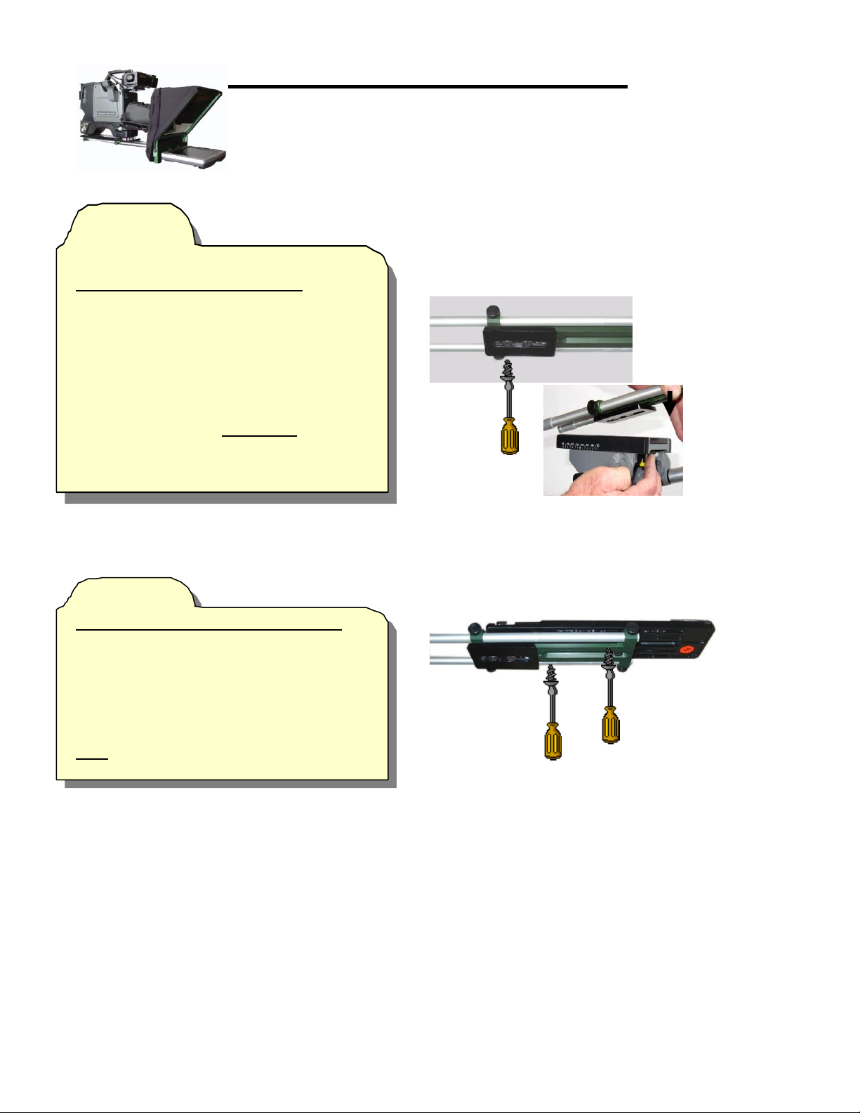
Step 1
Attach the GlidePlate to the tripod
Remove the wedge plate from the tripod.
Position the wedge plate over the threaded holes
on the bottom* of the GlidePlate. Using a flat head
screwdriver and the screws provided with the
wedge plate, attach the wedge plate to the
GlidePlate. Secure the configured GlidePlate to
the tripod and LOCK the video head.
*bottom = side with the beveled slot
(Figure 1)
Step 2
Attach the Camera Quick Release Plate)
Position the camera quick release plate over the
top (non beveled side) of the GlidePlate slot.
Attach the two pieces together by pushing two
flat head screws up through the bottom of the
slot and into the appropriate threaded holes in the
quick release plate.
Hint: Loosely tighten screws at this point to allow
for easy adjustment. (Figure 2)
Page 8
8
Figure 3
HINT: If the reflective (correct) side of the BeamSplitter
is not marked (black dot in one of the corners) it can be
identified using a pointed object like a pencil or a key. With
the glass at an angle (about 45 degrees), hold the pointed
object as close to the BeamSplitter surface as possible
without touching it. If the image is sharp and clear then it
Figure 4
Figure 5
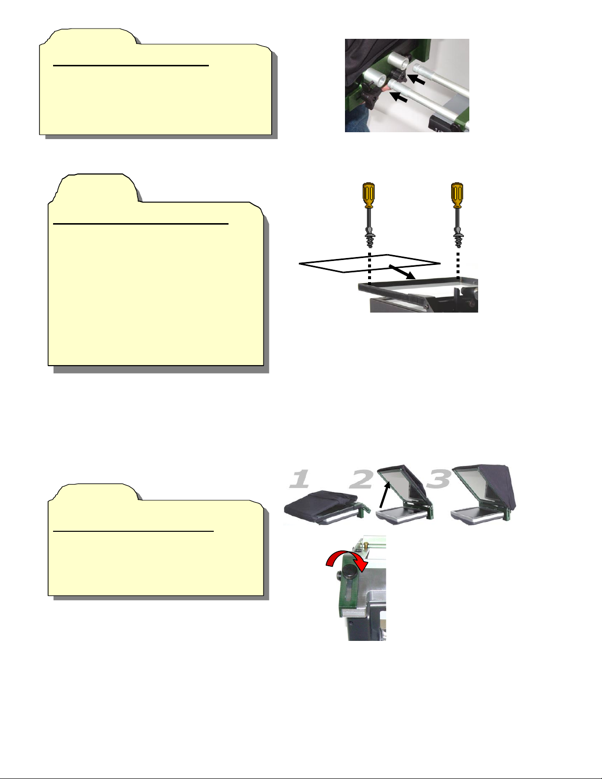
Step 3
Attach the monitor and LensView
Leave LensView folded down. Loosen the
thumbscrews on the monitor/LensView assembly
collars. Slide collars onto the GlidePlate rods
and secure with thumbscrews.
(Figure 3)
Step 4
Insert the BeamSplitter into the frame
If beamsplitter is already in place skip to
Step 5. If the folding hood is velcroed to the
top portion of the frame, remove it.
Completely remove the 2 slotted screws on the
inside of the top of the frame. Remove the top
of the frame. Position the beamsplitter with the
correct side facing down and slide it forward
and down the channel (under any protruding
screws) until it rests on the bottom of the frame.
Replace the top of the frame and secure with 2 slotted
screws.
(Figure 4)
Step 5
Rotate beamsplitter frame in place
Push up on the top of the folding frame to
rotate into place. Secure by inserting two
thumbscrews and turning until tight.
(Figure 5)
Page 9
9
Figure 6
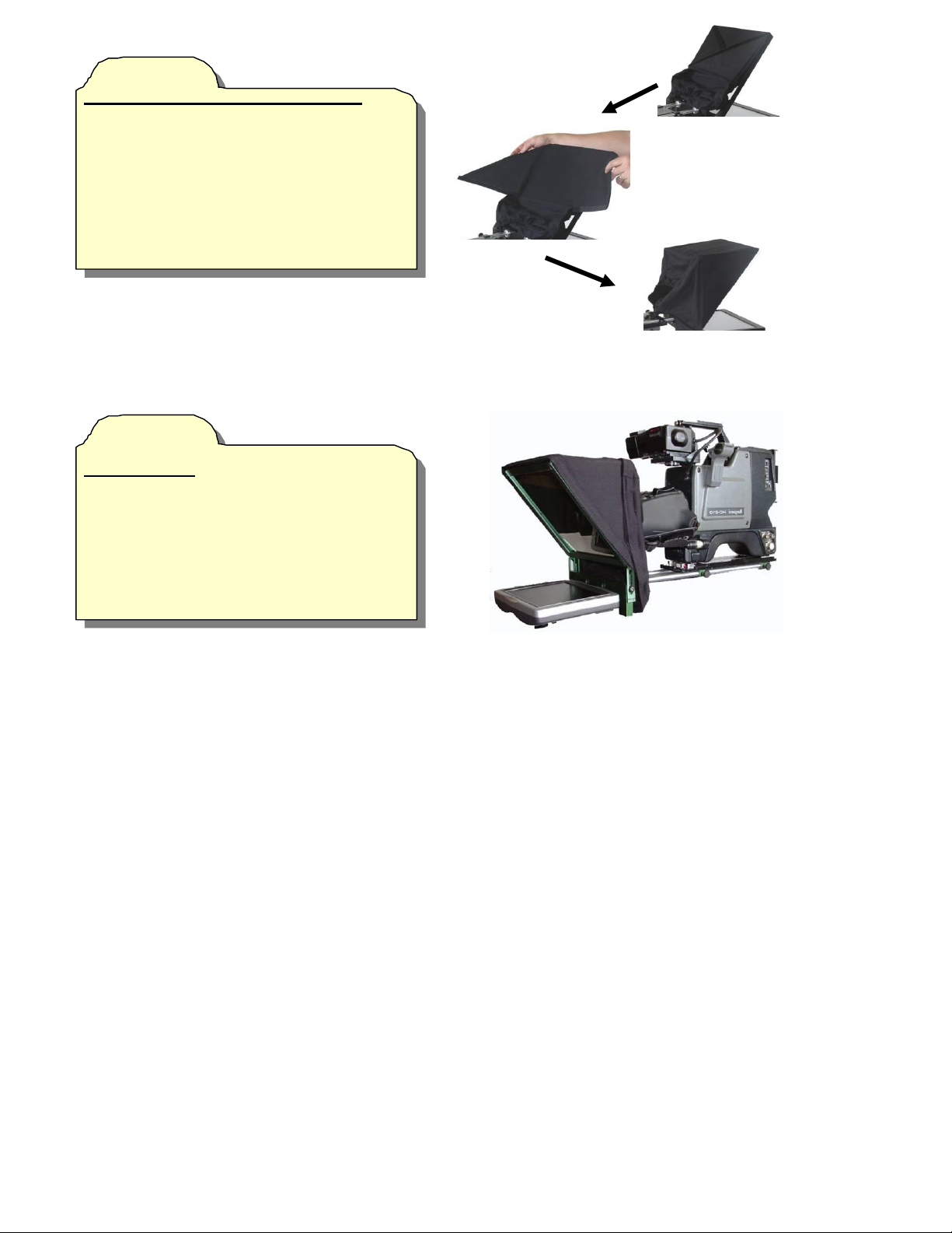
Step 6
Attach and unfold the hood and mask
Unfold the “wings” and simultaniously
press up so the velcro on the wings meets
the velcro on the sides of the frame.
Secure by lightly pressing along the edge
of the hood and frame. With the hood in place
position the mask and secure
it to the hood using the velcro in the
outside of the hood opening.
(Figure 6)
Step 7
Attach camera
Insert the camera into the Camera Quick
Release Plate that was attached to the
GlidePlate in Step 2. Pull the conical mask
around the lens and adjust the hood height if
necessary.
(Figure 7)
 Loading...