

Page 1

VoIPBox DSL
VoIPBox BRI
Reference Manual
Software version 20.0
Page 2

VoIPBox DSL / VoIPBox BRI
Reference Manual
TELES AG | HEADQUARTERS
Ernst-Reuter-Platz 8
10587 Berlin
GERMANY
Phone +49 30 399 28-066
Fax +49 30 399 28-051
E-mail [email protected]
http www.teles.com
© Copyright 2010 TELES AG Informationstechnologien. All rights reserved.
®
TELES
, IntraSTAR®, Intra*®, iGATE®, and iSWITCH® are registered trademarks of TELES AG
Informationstechnologien. All other trademarks used are the property of their respective owners.
The supplied hardware/software systems are protected by copyright and can be used solely by their lawful
owners.
All text and figures in this publication have been compiled with great attention to detail. Nonetheless,
inaccuracies and typographical errors cannot be entirely avoided. TELES AG Informationstechnologien
provides this document 'as is' without warranty of any kind, expressed or implied. TELES AG
Informationstechnologien reserves the right to make changes in product design or specifications without
notice.
Revised:2 July 2014 005Software version: – version:20.0
VoIPBox DSL / VoIPBox BRI – version:20.0.005
Page 3

Table of contents
Table of contents
1 About this manual. . . . . . . . . . . . . . . . . . . . . . . . . . . . . . . . . . . . 6
1.1 Organization . . . . . . . . . . . . . . . . . . . . . . . . . . . . . . . . . . . . . . . . . . . . . . . . . . . . . . . . . .7
1.2 Conventions. . . . . . . . . . . . . . . . . . . . . . . . . . . . . . . . . . . . . . . . . . . . . . . . . . . . . . . . . . .7
1.3 Safety Symbols . . . . . . . . . . . . . . . . . . . . . . . . . . . . . . . . . . . . . . . . . . . . . . . . . . . . . . . .8
2 Safety and security precautions. . . . . . . . . . . . . . . . . . . . . . . . . 9
2.1 Safety Measures . . . . . . . . . . . . . . . . . . . . . . . . . . . . . . . . . . . . . . . . . . . . . . . . . . . . . .10
2.2 Power Supply. . . . . . . . . . . . . . . . . . . . . . . . . . . . . . . . . . . . . . . . . . . . . . . . . . . . . . . . .10
2.2.1 Technical Data . . . . . . . . . . . . . . . . . . . . . . . . . . . . . . . . . . . . . . . . . . . . . . . . . . . . . . . .10
2.2.2 Symbols . . . . . . . . . . . . . . . . . . . . . . . . . . . . . . . . . . . . . . . . . . . . . . . . . . . . . . . . . . . . .10
2.2.3 Instructions for Use . . . . . . . . . . . . . . . . . . . . . . . . . . . . . . . . . . . . . . . . . . . . . . . . . . . .11
2.2.4 Safety Precautions . . . . . . . . . . . . . . . . . . . . . . . . . . . . . . . . . . . . . . . . . . . . . . . . . . . . .11
2.3 Jacks . . . . . . . . . . . . . . . . . . . . . . . . . . . . . . . . . . . . . . . . . . . . . . . . . . . . . . . . . . . . . . . .11
2.4 EMC Protection . . . . . . . . . . . . . . . . . . . . . . . . . . . . . . . . . . . . . . . . . . . . . . . . . . . . . . .11
2.5 System Security . . . . . . . . . . . . . . . . . . . . . . . . . . . . . . . . . . . . . . . . . . . . . . . . . . . . . . .11
2.5.1 Servicing the VoIPBox . . . . . . . . . . . . . . . . . . . . . . . . . . . . . . . . . . . . . . . . . . . . . . . . . .12
2.5.2 Protecting the Operating System. . . . . . . . . . . . . . . . . . . . . . . . . . . . . . . . . . . . . . . . .12
2.6 CDR Files. . . . . . . . . . . . . . . . . . . . . . . . . . . . . . . . . . . . . . . . . . . . . . . . . . . . . . . . . . . . .12
2.7 Network Security. . . . . . . . . . . . . . . . . . . . . . . . . . . . . . . . . . . . . . . . . . . . . . . . . . . . . .12
3 Overview . . . . . . . . . . . . . . . . . . . . . . . . . . . . . . . . . . . . . . . . . . 14
3.1 Features . . . . . . . . . . . . . . . . . . . . . . . . . . . . . . . . . . . . . . . . . . . . . . . . . . . . . . . . . . . . .15
3.2 Implementation scenarios . . . . . . . . . . . . . . . . . . . . . . . . . . . . . . . . . . . . . . . . . . . . . .16
4 VoIPBox installation . . . . . . . . . . . . . . . . . . . . . . . . . . . . . . . . . 18
4.1 Checklist. . . . . . . . . . . . . . . . . . . . . . . . . . . . . . . . . . . . . . . . . . . . . . . . . . . . . . . . . . . . .19
4.2 Package Contents . . . . . . . . . . . . . . . . . . . . . . . . . . . . . . . . . . . . . . . . . . . . . . . . . . . . .19
4.3 VoIPBox Hardware Description . . . . . . . . . . . . . . . . . . . . . . . . . . . . . . . . . . . . . . . . . .19
4.4 Installation Requirements. . . . . . . . . . . . . . . . . . . . . . . . . . . . . . . . . . . . . . . . . . . . . . .20
4.4.1 ISDN Wiring . . . . . . . . . . . . . . . . . . . . . . . . . . . . . . . . . . . . . . . . . . . . . . . . . . . . . . . . . .20
4.4.2 Ethernet Wiring. . . . . . . . . . . . . . . . . . . . . . . . . . . . . . . . . . . . . . . . . . . . . . . . . . . . . . .21
4.5 Preparing for Installation . . . . . . . . . . . . . . . . . . . . . . . . . . . . . . . . . . . . . . . . . . . . . . .21
4.6 Hardware Connection. . . . . . . . . . . . . . . . . . . . . . . . . . . . . . . . . . . . . . . . . . . . . . . . . .21
4.7 LED Functionality. . . . . . . . . . . . . . . . . . . . . . . . . . . . . . . . . . . . . . . . . . . . . . . . . . . . . .22
4.8 GATE Manager. . . . . . . . . . . . . . . . . . . . . . . . . . . . . . . . . . . . . . . . . . . . . . . . . . . . . . . .22
4.9 Transfer the config file with the GATE Manager to the PC . . . . . . . . . . . . . . . . . . . .23
4.10 Activate the DSL connection . . . . . . . . . . . . . . . . . . . . . . . . . . . . . . . . . . . . . . . . . . . .23
4.11 Activate the VoIP interface. . . . . . . . . . . . . . . . . . . . . . . . . . . . . . . . . . . . . . . . . . . . . .25
4.12 Changing the IP settings and/or deactivate DHCP . . . . . . . . . . . . . . . . . . . . . . . . . . .26
4.13 Remote access security . . . . . . . . . . . . . . . . . . . . . . . . . . . . . . . . . . . . . . . . . . . . . . . . .27
4.13.1 Graphical User Interface . . . . . . . . . . . . . . . . . . . . . . . . . . . . . . . . . . . . . . . . . . . . . . . .27
4.13.2 Setting a Password for Remote Access. . . . . . . . . . . . . . . . . . . . . . . . . . . . . . . . . . . . .28
4.13.3 Adjust the firewall settings. . . . . . . . . . . . . . . . . . . . . . . . . . . . . . . . . . . . . . . . . . . . . .29
5 Configuration files. . . . . . . . . . . . . . . . . . . . . . . . . . . . . . . . . . . 30
5.1 Configuration file ip.cfg . . . . . . . . . . . . . . . . . . . . . . . . . . . . . . . . . . . . . . . . . . . . . . . .32
5.1.1 System section configuration . . . . . . . . . . . . . . . . . . . . . . . . . . . . . . . . . . . . . . . . . . . .32
5.1.2 Ethernet interface configuration . . . . . . . . . . . . . . . . . . . . . . . . . . . . . . . . . . . . . . . . .33
5.1.3 GUI settings . . . . . . . . . . . . . . . . . . . . . . . . . . . . . . . . . . . . . . . . . . . . . . . . . . . . . . . . . .33
VoIPBox DSL / VoIPBox BRI
– version:20.0.005
Page 3
Page 4

Table of contents
5.1.4 DSL configuration . . . . . . . . . . . . . . . . . . . . . . . . . . . . . . . . . . . . . . . . . . . . . . . . . . . . .33
5.1.5 Firewall configuration. . . . . . . . . . . . . . . . . . . . . . . . . . . . . . . . . . . . . . . . . . . . . . . . . .33
5.1.6 PPPoE Configuration . . . . . . . . . . . . . . . . . . . . . . . . . . . . . . . . . . . . . . . . . . . . . . . . . . .35
5.1.7 DHCP and DNSmasq settings . . . . . . . . . . . . . . . . . . . . . . . . . . . . . . . . . . . . . . . . . . . .35
5.2 Configuration File pabx.cfg . . . . . . . . . . . . . . . . . . . . . . . . . . . . . . . . . . . . . . . . . . . . .36
5.2.1 System Settings . . . . . . . . . . . . . . . . . . . . . . . . . . . . . . . . . . . . . . . . . . . . . . . . . . . . . . .36
5.2.1.1 VoIPBox DSL / VoIPBox BRI name . . . . . . . . . . . . . . . . . . . . . . . . . . . . . . . . . . . . . . . . .37
5.2.1.2 Log Files . . . . . . . . . . . . . . . . . . . . . . . . . . . . . . . . . . . . . . . . . . . . . . . . . . . . . . . . . . . . .37
5.2.1.3 NTP settings . . . . . . . . . . . . . . . . . . . . . . . . . . . . . . . . . . . . . . . . . . . . . . . . . . . . . . . . . .39
5.2.1.4 Controller settings. . . . . . . . . . . . . . . . . . . . . . . . . . . . . . . . . . . . . . . . . . . . . . . . . . . . .41
5.2.1.5 Subscriber settings. . . . . . . . . . . . . . . . . . . . . . . . . . . . . . . . . . . . . . . . . . . . . . . . . . . . .42
5.2.2 SMTP-Client Configuration . . . . . . . . . . . . . . . . . . . . . . . . . . . . . . . . . . . . . . . . . . . . . .43
5.2.3 SNMP Settings . . . . . . . . . . . . . . . . . . . . . . . . . . . . . . . . . . . . . . . . . . . . . . . . . . . . . . . .45
5.2.4 Night Configuration . . . . . . . . . . . . . . . . . . . . . . . . . . . . . . . . . . . . . . . . . . . . . . . . . . .45
5.3 Configuration File route.cfg. . . . . . . . . . . . . . . . . . . . . . . . . . . . . . . . . . . . . . . . . . . . .46
5.3.1 Entries in the Sections [System] and [Night<num>] . . . . . . . . . . . . . . . . . . . . . . . . . .46
5.3.1.1 Restrict . . . . . . . . . . . . . . . . . . . . . . . . . . . . . . . . . . . . . . . . . . . . . . . . . . . . . . . . . . . . . .46
5.3.1.2 MapAll . . . . . . . . . . . . . . . . . . . . . . . . . . . . . . . . . . . . . . . . . . . . . . . . . . . . . . . . . . . . . .48
5.3.1.3 Redirect . . . . . . . . . . . . . . . . . . . . . . . . . . . . . . . . . . . . . . . . . . . . . . . . . . . . . . . . . . . . .49
5.3.2 VoIP Profiles. . . . . . . . . . . . . . . . . . . . . . . . . . . . . . . . . . . . . . . . . . . . . . . . . . . . . . . . . .51
5.3.3 Gatekeeper Profiles. . . . . . . . . . . . . . . . . . . . . . . . . . . . . . . . . . . . . . . . . . . . . . . . . . . .54
5.3.4 Registrar Profiles . . . . . . . . . . . . . . . . . . . . . . . . . . . . . . . . . . . . . . . . . . . . . . . . . . . . . .55
5.3.5 Radius Profiles . . . . . . . . . . . . . . . . . . . . . . . . . . . . . . . . . . . . . . . . . . . . . . . . . . . . . . . .56
6 Additional VoIP parameters . . . . . . . . . . . . . . . . . . . . . . . . . . . 58
6.1 Signaling parameters . . . . . . . . . . . . . . . . . . . . . . . . . . . . . . . . . . . . . . . . . . . . . . . . . .59
6.2 Set up the as Registrar. . . . . . . . . . . . . . . . . . . . . . . . . . . . . . . . . . . . . . . . . . . . . . . . .66
6.3 Routing parameters . . . . . . . . . . . . . . . . . . . . . . . . . . . . . . . . . . . . . . . . . . . . . . . . . . .67
6.4 Quality parameters . . . . . . . . . . . . . . . . . . . . . . . . . . . . . . . . . . . . . . . . . . . . . . . . . . . .68
6.5 Interworking parameter. . . . . . . . . . . . . . . . . . . . . . . . . . . . . . . . . . . . . . . . . . . . . . . .71
6.6 Compression parameters . . . . . . . . . . . . . . . . . . . . . . . . . . . . . . . . . . . . . . . . . . . . . . .71
6.7 Fax/modem parameters . . . . . . . . . . . . . . . . . . . . . . . . . . . . . . . . . . . . . . . . . . . . . . . .72
6.7.1 Fax settings for T.38 . . . . . . . . . . . . . . . . . . . . . . . . . . . . . . . . . . . . . . . . . . . . . . . . . . .73
6.8 DTMF parameters . . . . . . . . . . . . . . . . . . . . . . . . . . . . . . . . . . . . . . . . . . . . . . . . . . . . .74
7 System maintenance and software update. . . . . . . . . . . . . . . 75
7.1 Configuration errors . . . . . . . . . . . . . . . . . . . . . . . . . . . . . . . . . . . . . . . . . . . . . . . . . . .76
7.2 Status and error messages . . . . . . . . . . . . . . . . . . . . . . . . . . . . . . . . . . . . . . . . . . . . . .76
7.3 SNMP agent . . . . . . . . . . . . . . . . . . . . . . . . . . . . . . . . . . . . . . . . . . . . . . . . . . . . . . . . . .80
7.4 DNS forwarder. . . . . . . . . . . . . . . . . . . . . . . . . . . . . . . . . . . . . . . . . . . . . . . . . . . . . . . .83
7.5 ipupdate - DynDNS client . . . . . . . . . . . . . . . . . . . . . . . . . . . . . . . . . . . . . . . . . . . . . . .83
7.6 Trace. . . . . . . . . . . . . . . . . . . . . . . . . . . . . . . . . . . . . . . . . . . . . . . . . . . . . . . . . . . . . . . .85
7.6.1 ISDN trace output . . . . . . . . . . . . . . . . . . . . . . . . . . . . . . . . . . . . . . . . . . . . . . . . . . . . .88
7.6.2 Call forwarding to SIP trace output . . . . . . . . . . . . . . . . . . . . . . . . . . . . . . . . . . . . . . .88
7.6.3 VoIP trace output . . . . . . . . . . . . . . . . . . . . . . . . . . . . . . . . . . . . . . . . . . . . . . . . . . . . .89
7.6.3.1 Interface IP network . . . . . . . . . . . . . . . . . . . . . . . . . . . . . . . . . . . . . . . . . . . . . . . . . . .90
7.6.3.2 RTP/RTCP output . . . . . . . . . . . . . . . . . . . . . . . . . . . . . . . . . . . . . . . . . . . . . . . . . . . . . .93
7.6.3.3 Internal protocol interface (to ISDN, POTS, mobile) . . . . . . . . . . . . . . . . . . . . . . . . . .97
7.6.3.4 H.245 messages . . . . . . . . . . . . . . . . . . . . . . . . . . . . . . . . . . . . . . . . . . . . . . . . . . . . . . .99
7.6.3.5 RAS (Registration, Admission, Status) . . . . . . . . . . . . . . . . . . . . . . . . . . . . . . . . . . . .103
7.6.3.6 ENUM output. . . . . . . . . . . . . . . . . . . . . . . . . . . . . . . . . . . . . . . . . . . . . . . . . . . . . . . .107
VoIPBox DSL / VoIPBox BRI
– version:20.0.005
Page 4
Page 5

Table of contents
7.6.4 Remote output . . . . . . . . . . . . . . . . . . . . . . . . . . . . . . . . . . . . . . . . . . . . . . . . . . . . . .107
7.6.5 DTMF tone trace output . . . . . . . . . . . . . . . . . . . . . . . . . . . . . . . . . . . . . . . . . . . . . . .108
7.7 Software Update. . . . . . . . . . . . . . . . . . . . . . . . . . . . . . . . . . . . . . . . . . . . . . . . . . . . .109
8 Online traffic monitor . . . . . . . . . . . . . . . . . . . . . . . . . . . . . . . 111
8.1 Calculating and resetting statistic values, resetting counters. . . . . . . . . . . . . . . . .112
8.1.1 Calculation and resetting of statistic values . . . . . . . . . . . . . . . . . . . . . . . . . . . . . . .112
8.1.2 Additional resetting of counters A-F . . . . . . . . . . . . . . . . . . . . . . . . . . . . . . . . . . . . .113
8.1.3 Resetting statistic counters . . . . . . . . . . . . . . . . . . . . . . . . . . . . . . . . . . . . . . . . . . . . .114
8.2 Generating and retrieving CDRs . . . . . . . . . . . . . . . . . . . . . . . . . . . . . . . . . . . . . . . .114
8.2.1 Call log . . . . . . . . . . . . . . . . . . . . . . . . . . . . . . . . . . . . . . . . . . . . . . . . . . . . . . . . . . . . .115
8.2.2 Missed calls list. . . . . . . . . . . . . . . . . . . . . . . . . . . . . . . . . . . . . . . . . . . . . . . . . . . . . . .117
8.3 Sending CDRs via e-mail. . . . . . . . . . . . . . . . . . . . . . . . . . . . . . . . . . . . . . . . . . . . . . .118
9 Troubleshooting . . . . . . . . . . . . . . . . . . . . . . . . . . . . . . . . . . . 119
9.1 No connection to the system . . . . . . . . . . . . . . . . . . . . . . . . . . . . . . . . . . . . . . . . . . .120
9.1.1 System does not start correctly. . . . . . . . . . . . . . . . . . . . . . . . . . . . . . . . . . . . . . . . . .120
9.1.2 Web interface is not accessible. . . . . . . . . . . . . . . . . . . . . . . . . . . . . . . . . . . . . . . . . .121
9.1.3 IP address settings . . . . . . . . . . . . . . . . . . . . . . . . . . . . . . . . . . . . . . . . . . . . . . . . . . . .122
9.1.4 Firewall issues and NAT / PAT settings. . . . . . . . . . . . . . . . . . . . . . . . . . . . . . . . . . . .122
9.1.5 ISDN dial-in number missing or wrong . . . . . . . . . . . . . . . . . . . . . . . . . . . . . . . . . . .122
9.1.6 ISDN port not loaded correctly / not active . . . . . . . . . . . . . . . . . . . . . . . . . . . . . . . .123
9.2 No calls are possible . . . . . . . . . . . . . . . . . . . . . . . . . . . . . . . . . . . . . . . . . . . . . . . . . .124
9.2.1 Call does not arrive on the gateway . . . . . . . . . . . . . . . . . . . . . . . . . . . . . . . . . . . . .124
9.2.2 Call is rejected or not routed to the right destination address . . . . . . . . . . . . . . . .126
9.3 Software update problems. . . . . . . . . . . . . . . . . . . . . . . . . . . . . . . . . . . . . . . . . . . . .129
10.1 pabx.cfg . . . . . . . . . . . . . . . . . . . . . . . . . . . . . . . . . . . . . . . . . . . . . . . . . . . . . . . . . . . .131
10.2 ip.cfg. . . . . . . . . . . . . . . . . . . . . . . . . . . . . . . . . . . . . . . . . . . . . . . . . . . . . . . . . . . . . . .131
10.3 route.cfg. . . . . . . . . . . . . . . . . . . . . . . . . . . . . . . . . . . . . . . . . . . . . . . . . . . . . . . . . . . .132
VoIPBox DSL / VoIPBox BRI
– version:20.0.005
Page 5
Page 6

1 About this manual
Page 7

1 About this manual
This manual is set up to guide you through the step-by-step installation of your gateway so
that you can follow it through from the front to the back. Make sure you familiarize yourself
thoroughly with the safety and security precautions detailed in Chapter 2 Safety and security
precautions before you begin to install your gateway. TELES is not liable for any damage or
injury resulting from a failure to follow these safety and security instructions!
1.1 Organization
This manual is organized into the following chapters.
Chapter 1 About this manual introduces this VoIPBox Systems Manual.
Chapter 2 Safety and security precautions contains information about security issues
relevant to connection with the IP network.
Chapter 3 Overview briefly describes the VoIPBox and its implementation scenarios.
Chapter 4 VoIPBox installation contains information on how to connect and configure
the system so that it is ready for operation.
Chapter 5 Configuration files describes the VoIPBox’s configuration files.
Chapter 7 System maintenance and software update describes system messages that
are saved in the protocol file, as well as trace options.
Chapter 8 Online traffic monitor contains the configuration for monitoring the system’s
statistics and CDRs.
Chapter 12 Additional VoIP parameters contains additional configuration entries to
fine-tune communication with the VoIP peer.
Chapter 9 Troubleshooting contains troubleshooting suggestions.
1.2 Conventions
This document uses the following typographic conventions:
Bold – items from the GUI menu.
Halfbold – items from the GUI and the menu.
Code – file names, variables and constants in configuration files or commands in body
text.
"Conventions" on page 7 – cross-references can be accessed in the PDF files by a single
mouse click.
Configuration data or extracts are written in single-column tables with a gray background.
VoIPBox DSL / VoIPBox BRI – version:20.0.005
Page 7
Page 8
1 About this manual
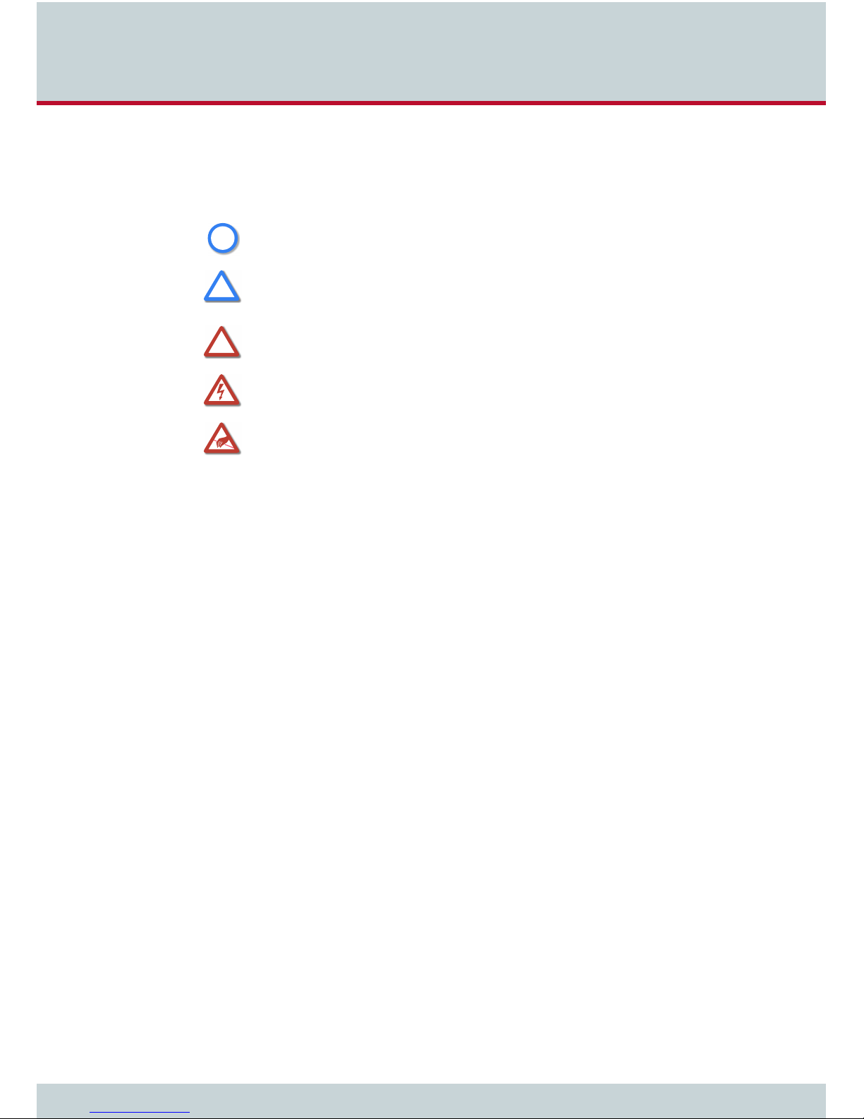
1.3 Safety Symbols
The following symbols are used to indicate important information and to describe levels of
possible danger.
Note
i
i
Useful information with no safety implications.
Attention
!
!
!
!
Information that must be adhered to as it is necessary to ensure that the system functions correctly and to avoid material damage.
Warning
Danger. Could cause personal injury or damage to the system.
Dangerous voltage
Could cause injury by high voltage and/or damage the system.
Electrostatic discharge
Components at risk of discharge must be grounded before being touched.
VoIPBox DSL / VoIPBox BRI – version:20.0.005
Page 8
Page 9

2 Safety and security precautions
Page 10
2 Safety and security precautions
This chapter contains the safety and security precautions. Please be sure and take
time to read this section to ensure your personal safety and proper operation of your
gateway. To avoid personal injury or damage to the system, please follow all safety
instructions before you begin working on your gateway. VoIPBoxes are CE certified
and fulfill all relevant security requirements. The manufacturer assumes no liability
for consequential damages or for damages resulting from unauthorized changes.
2.1 Safety Measures
Danger of electric shock - the power supplies run on 230 V. Do not open the VoIPBox or its
power supply.
Make sure to install the VoIPBox near the power source and that the power source is easily
accessible.
Bear in mind that telephone and WAN lines are also energized and can cause electric shocks.
Be sure to respect country-specific regulations, standards or guidelines for accident prevention.
2.2 Power Supply
The included power supply is to be used exclusively for operation of your VoIPBox.
Make sure you read this chapter thoroughly and save the instructions for future reference. Use
i
i
only the power supply included in the package contents of your VoIPBox.
2.2.1 Technical Data
The following list includes technical information on the power supply:
Type: DSA-15P-12 EU 120150 for VoIPBox
Input voltage: 110-230V~ +/-15% 50-60Hz; 0.5A
Output voltage: 12V
Weight: 115g
Tested and certified as per EN60950-1
2.2.2 Symbols
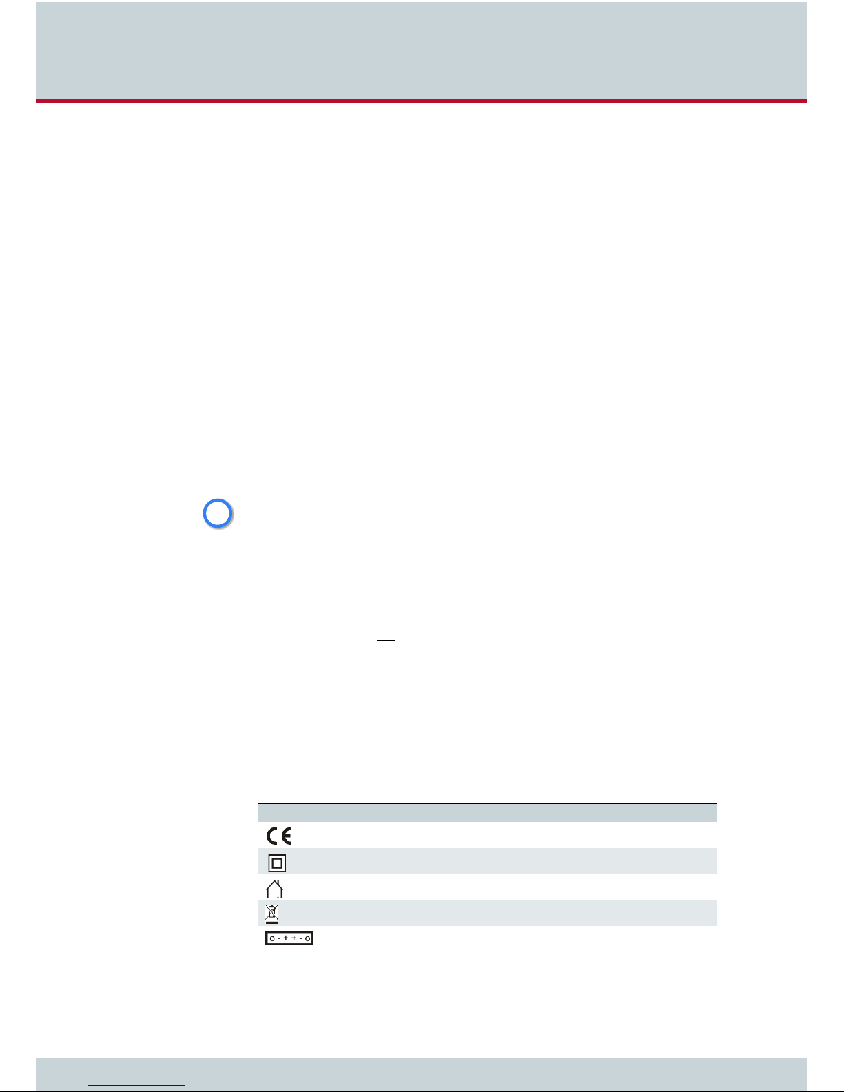
The symbols on the power supply have the following meanings:
Table 2.1 Power Supply Symbols
Symbol Meaning
---
; 1.25A
Certified to conform with European norms.
Protective insulation provided.
For indoor use only.
VoIPBox DSL / VoIPBox BRI – version:20.0.005
Not for public disposal. Make sure you dispose of the power supply properly.
Indicates the output polarity of the power supply.
Page 10
Page 11
2 Safety and security precautions
2.2.3 Instructions for Use
Plug the power supply directly into the outlet. The power supply provides safety-low voltage
with limited capacity for your VoIPBox.
Use only the power supply included in the package contents of your VoIPBox.
i
i
The devices are designed for constant use in dry, indoor locations. However, we recommend
that you unplug them if you do not intend to use them for an extended amount of time. Make
sure the power outlet is easily accessible at all times.
2.2.4 Safety Precautions
Make sure you follow these safety precautions:
Electrical devices may not be used by individuals who are not aware of the dangers of
electricity and/or the incorrect use thereof.
Make sure you use only the correct input voltage.
Make sure the installation site is sufficiently ventilated.
Use the device only in dry, indoor locations, and protect it from humidity.
Do not subject the device to direct sunlight.
Unplug the device if you do not intend to use it for an extended amount of time.
Hold the device by its housing when you unplug it. Wall outlets can become
mechanically overloaded; do not pull on the cord.
The room temperature may not exceed 35°C.
Do not use the device if it is damaged or if there are signs of misfunction. In this case,
send it to TELES Service or dispose of it properly (not with household waste).
2.3 Jacks
The jacks on the VoIPBox have fulfilled the requirements of the SELV safety standard.
2.4 EMC Protection
Use shielded cables.
Do not remove any housing components. They provide EMC protection.
2.5 System Security
This section describes all points crucial to the VoIPBox’s system security.
The VoIPBox’s location must support normal operation according to EN ETS 300 386. Be sure
to select the location with the following conditions in mind:
Location: Make sure you install the system in a clean, dry, dust-free location. If possible, use
!
!
an air-conditioned site. The site must be free of strong electrical or magnetic fields, which
cause disrupted signals and, in extreme cases, system failure.
VoIPBox DSL / VoIPBox BRI – version:20.0.005
Page 11
Page 12

2 Safety and security precautions
Temperature: The site must maintain a temperature between 0 and 35°C. Be sure to guard
!
!
2.5.1 Servicing the VoIPBox
2.5.2 Protecting the Operating System
against temperature fluctuations. Resulting condensation can cause short circuiting. The humidity level may not exceed 80%.
To avoid overheating the system, make sure the site provides adequate ventilation.
Power: The site must contain a central emergency switch for the entire power source.
The site’s fuses must be calculated to provide adequate system security. The electrical facilities
must comply with applicable regulations.
The operating voltage and frequency may not exceed or fall below what is stated on the label.
Regular servicing ensures that your VoIPBox runs trouble-free. Servicing also includes looking
after the room in which the system is set up. Ensure that the air-conditioning and its filter
system are regularly checked and that the premises are cleaned on a regular basis.
Changing configuration data may lead to malfunctions and/or misrouting, as well as possible
consequential damage. Make changes at your own risk. TELES is not liable for any possible
damage resulting from or in relation to such changes. Please thoroughly check any changes
you or a third party have made to your configuration!
To make changes in or perform tests on the database, make sure your flash disk contains
enough storage space. Downloading the log files and deleting them from the VoIPBox on a
regular basis will ensure your VoIPBox’s reliability.
Be careful when deleting files that you do not delete any files necessary for system operation.To check storage space and/or delete files, use GATE Manager. For more information see
the document TELES.GATE Manager. All files with the extension
save files before deleting them, use the Receive File option in GATE Manager.
*.log can be deleted. To
2.6 CDR Files
Call Detail Records are intended for analysis of the VoIPBox’s activity only. They are not designed to be used for billing purposes, as it may occur that the times they record are not exact.
Inaccuracies in the generation of CDRs may occur for active connections if traffic is flowing on
i
i
the system while modifications in configuration or routing files are activated.
2.7 Network Security
Every day, hackers develop new ways to break into systems through the Internet. While TELES
takes great care to ensure the security of its systems, any system with access through the Internet is only as secure as its user makes it. Therefore, to avoid unwanted security breaches
and resulting system malfunctions, you must take the following steps to secure your VoIPBox
if you connect it to the Internet:
Use the installed firewall.
Access to the VoIPBox via GATE Manager must be password protected. Do not use
obvious passwords (anything from
in mind: the password that is easiest to remember is also likely to be easiest to crack.
sesame to your mother-in-laws maiden name). Bear
VoIPBox DSL / VoIPBox BRI – version:20.0.005
Page 12
Page 13

2 Safety and security precautions
For operation and remote administration of your VoIPBox open only the following ports only
when the indicated services are used:
Table 2.2 Default Ports Used for Specific Services
Service Protocol Port
FTP TCP 21 (default, can be set)
Telnet (for TELES debug access only) TCP 23 (default, can be set)
SMTP TCP 25 (default, can be set)
DNS forward UDP 53
HTTP TCP 80 (default, can be set)
NTP UDP 123
SNMP UDP 161 (default, can be set)
H.225 registration, admission, status UDP 1719 (default, can be set)
H.225 signaling TCP 1720 (default, can be set)
Radius UDP 1812 (default, can be set)
Radius accounting UDP 1813 (default, can be set)
GATE Manager TCP 4445 (default, can be set)
SIP signaling UDP / TCP 5060 (default, can be set)
RTP UDP 29000-29120 (default, can be set)
NMS TCP 4444
VoIPBox DSL / VoIPBox BRI – version:20.0.005
Page 13
Page 14

3 Overview
Page 15

3Overview
This chapter gives you an overview over the VoIPBox DSL / VoIPBox BRI. All types of
VoIPBox DSL / VoIPBox BRI are listed, also the list of features and two implementation scenarios.
The VoIPBox BRI is a media converter that facilitates the connection of ISDN service equipment with a voice over IP (VoIP) network. It converts line-based transmission on the ISDN side
to packet-based transmission in the IP network and vice versa. Incoming traffic arrives at one
VoIPBox, which routes the calls accordingly, depending on the call’s destination and attributes. The VoIPBox is available with two, four, or eight BRI ports.
The VoIPBox BRI Family includes the following variations:
VoIP Box DSL 2
VoIP Box DSL 4
VoIP Box DSL 8
VoIPBox BRI 2
VoIPBox BRI 4
VoIPBox BRI 8
3.1 Features
VoIP
upt to 16 media channels
H.323 v.4 / SIP v.2 signaling (RFC 3261), operating in parallel
Various audio codecs: G.711, G.729, G.168
Fax: T.38 fallback to G.711
Data: clear channel (RFC 4040)
ENUM client
Echo cancellation G.168–2000
Silence suppression, comfort noise generation, voice activity detection
Support for multiple gatekeepers and multiple registrars
Traffic shaping
Configurable time interval for echo detection in VoIP
ISDN
2, 4, or 8 BRI NT ports, port 1 is configurable as TE or NT
DSS1 (Q.931, national variants),Q.SIG-BC;
PP or PMP
DSL
ADSL2+/VDSL Modem
PPP or DHCP
VLAN or virtual path of ATM cell support
TR-069
LCR Engine
Multiple VoIP-carrier logins
Multiple ISDN routing methods
Multilevel alternative routing
dialed digit manipualtion
time depending call routing
Two-stage-dialing
VoIPBox DSL / VoIPBox BRI – version:20.0.005
Page 15
Page 16
3Overview
General
User-friendly GUI with easy and advanced mode configuration settings
Ringtone generation
Configurable ToS/DivServ
AOC generation
Integrated DSL router (PPPoE)
Integrated mail client capable of SMTP authentication
E-mail messages can trigger calls and play attached announcements
Automatic test call
Redial function
Autodial function
3.2 Implementation scenarios
These are the most commonly used implementation scenarios.
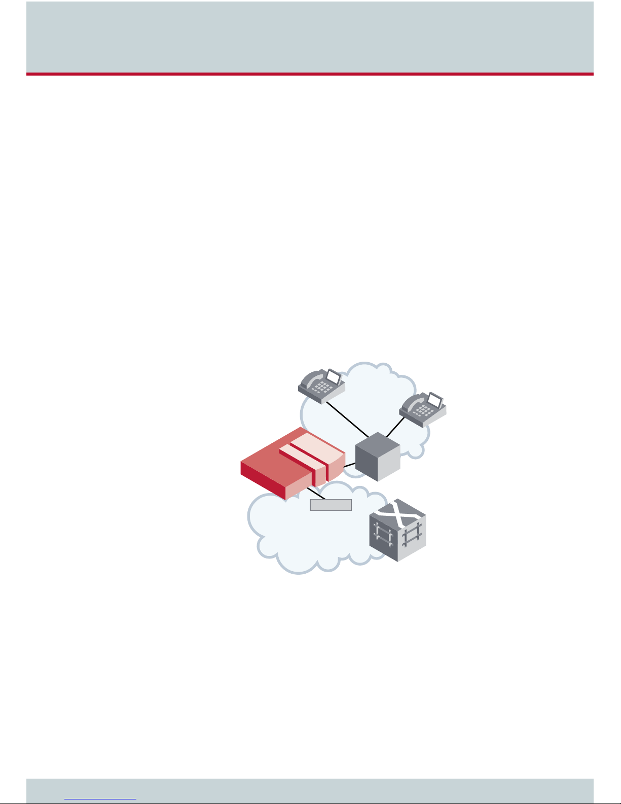
VoIP gateway
The VoIPBox’s sophisticated routing algorithms allow VoIP communication via SIP server and/
or gatekeeper (H.323), as well as multi-destination operation without a SIP Server or gatekeeper. Various voice codecs ensure universal connection to different VoIP destinations. Fax
transmission occurs via T.38 or fallback to G.711a.
Figure 3.1 VoIP gateway
VoIPBox BRI
Internet
ISDN
PBX
DSL/LAN
Local Exchange
VoIPBox DSL / VoIPBox BRI – version:20.0.005
Page 16
Page 17
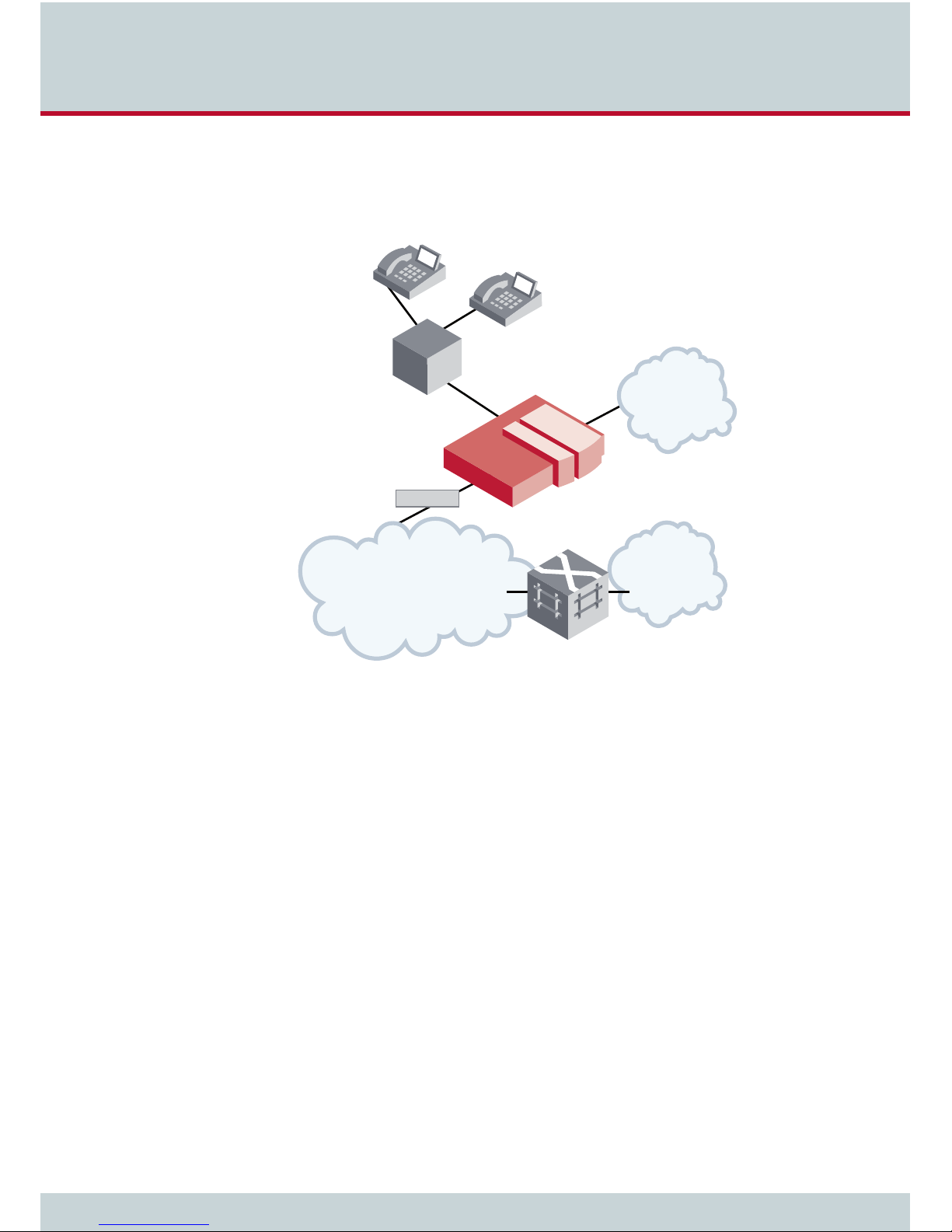
3Overview
Least cost router 2nd generation
The VoIPBox’s sophisticated routing algorithms serve as an LCR between your PBX and the
PSTN or VoIP carrier. Internet connection can occur via integrated DSL router. The system reverts to ISDN if there is an IP connection failure.
PBX
PSTN
VoIPBox BRI
DSL/LAN
Internet
Figure 3.2 Least cost router 2nd generation
Loca
VoIP
Carrier
l E
xch
an
g
e
VoIPBox DSL / VoIPBox BRI – version:20.0.005
Page 17
Page 18

4 VoIPBox installation
Page 19
4 VoIPBox installation
This chapter contains information on basic installation and configuration of your
VoIPBox. Follow the easy instructions to set up your VoIPBox in a matter of minutes.
Implementation of individual scenarios require adjustments to the appropriate interfaces. Tips for basic settings are described here. Links to relevant chapters are provided for more specific configuration changes.
4.1 Checklist
The following checklist provides step-by-step installation instructions.
1. Check the package contents
2. Connect the BRI lines to the PBX and/or the PSTN
3. Transfer the config files with the GATE Manager to the local computer.
4. Adjust the configuration to your needs (IP address and BRI / VoIP configuration).
5. Activate the configuration with the GATE Manager.
6. Secure the LAN connection
4.2 Package Contents
Your VoIPBox package contains the following components. Check the contents to make sure
everything is complete and undamaged. Immediately report any visible transport damages to
customer service. If damage exists, do not attempt operation without customer-service approval:
1 VoIPBox
1 power supply
4.3 VoIPBox Hardware Description
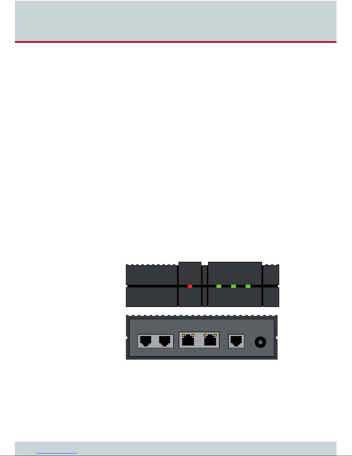
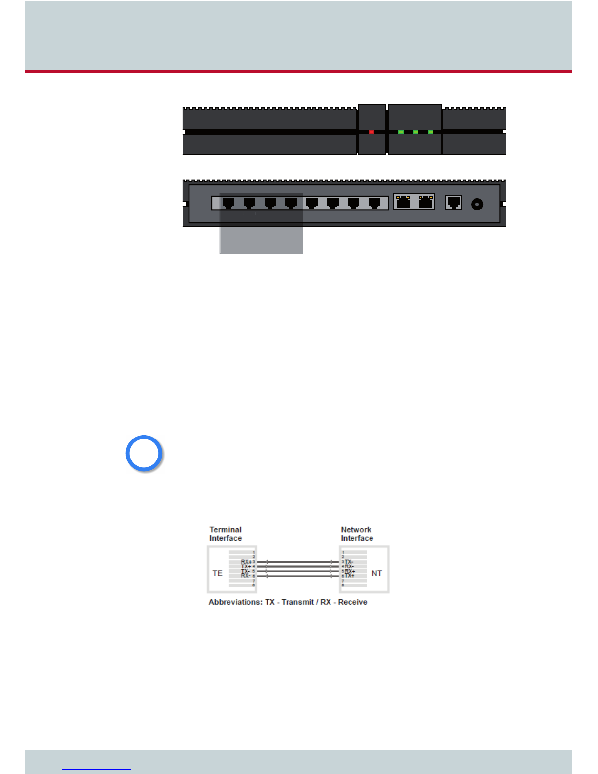
Figure 4.1 shows the front and rear view of all VoIPBox variations. The VoIPBox handles traffic
of up to 8/16 media channels. The following pages describe installation of the VoIPBox.
ISDN 2 ISDN 1 ETH2 ETH1 dsl 12 V-
Figure 4.1 VoIPBox BRI with 2 BRI and DSL: front and rear view
VoIPBox DSL / VoIPBox BRI – version:20.0.005
Page 19
Page 20
4 VoIPBox installation
ISDN 8
ISDN 7
ISDN 6
ISDN 5
ISDN ports Ethernet DSL
ISDN 8 ISDN 7 ISDN 6 ISDN 4ISDN 5 ISDN 3 ISDN 2 ISDN 1 ETH2 ETH1 12 V-
only available on
the VoIP BRI 8 box
Figure 4.2 VoIPBox BRI with 8 BRI and DSL: front and rear view
4.4 Installation Requirements
Before installing your VoIPBox, make sure you have the following connections in place:
ISDN BRI connection to PBX and/or to the PSTN
Power
4.4.1 ISDN Wiring
The TE ports connect to the PSTN and the NT ports connect to the PBX. Only the first port
ISDN1 can be configured as a TE port. It is also possible to configure port ISDN1 as NT to connect a telephone or PBX.
An attached NTBA or PBX must be connected to the ISDN1 TE outlet if it is to provide the clock
i
i
for the VoIPBox!
power
dsl
Figure 4.3 shows the standard pin assignment for TE and NT modes. You must change the
pin assignment if it differs on the connected equipment
Figure 4.3 ISDN Wiring Scheme
VoIPBox DSL / VoIPBox BRI – version:20.0.005
Page 20
Page 21

4 VoIPBox installation
4.4.2 Ethernet Wiring
To connect the VoIPBox’s Ethernet port to your local network, connect the system to an Ethernet switch in your network. Either one of the Ethernet ports can be used for the connection.
Both Ethernet ports are running in bridge mode, simular to a small Ethernet switch. In the
configuration file
ip.cfg the section [br0] is used for both IP interfaces.
4.5 Preparing for Installation
Here we have a difference between VoIPBox DSL and VoIPBox BRI:
a) The VoIP Box DSL comes with an active DHCP server.
b) The VoIP Box BRI has no DHCP server running.
Prepairing for installation on VoIPBox DSL
The VoIPBox DSL comes with a fix IP address (192.168.1.2/24) and an active DHCP server with
the address range 192.168.1.50 – 192.168.1.90. The VoIPBox DSL works as a default gateway in the network. In many cases no changes on the IP settings of the VoIPBox DLS are needed. Before changing the IP configuration please have the following information available:
new IP address and netmask in your local network for the VoIPBox DSL
new default gateway for VoIPBox DSL
Bear in mind that the preconfigured VoIPBox’s default IP address is 192.168.1.2. If this IP address is already being used in your local network, you must change the configuration before
i
i
you connect it to your local network. This can be done by connecting the VoIPBox DSL directly
to your computer via Ethernet cable.
Start the computer after connecting to the VoIPBox DSL so that a DHCP address is assigned
to the computer and follow the working steps described in Chapter 4.11 on page 25.
Preparing for installation on VoIPBox BRI
The VoIPBox BRI comes with a fix IP address (192.168.1.2/24). Use the Quickstart program to
set the IP address and the default gateway to the VoIPBox DSL. Do the following steps:
1. Open the TELES support page in a Web browser at http://195.4.12.8/agw/
2. Download the GateManager software, the Quickstart and the manual.
3. Extract the archives and install the Quickstart and the GateManager.
4. Follow the installation instructions.
5. Connect the VoIPBox BRI by Ethernet with a PC. Use any of the two IP interfaces of
the VoIPBox BRI.
6. Start the VoIPBox BRI by connecting the power supply.
7. Open Quickstart on the PC. It automatically finds your VoIPBox BRI. Double click the
icon to open the configuration window. Adjust the IP settings and click the finish
button. The VoIPBox BRI will be reconfigured with your new IP address and will then
re-start.
4.6 Hardware Connection
Do the following steps:
Connect your computer to the local network.
Connect the VoIPBox to the local network
Connect the VoIPBox to your PBX and/or the PSTN according to the required port
configuration.
Connect the VoIPBox to the power supply.
VoIPBox DSL / VoIPBox BRI – version:20.0.005
Page 21
Page 22
4 VoIPBox installation
4.7 LED Functionality
Each VoIPBox has the following status LEDs:
Table 4.1 VoIPBox LEDs
LED Name Description
Red Power On: Power on.
Green 1 DSL Off: inactive
Green 2 VoIP Off: inactive
Green 3 ISDN Off: inactive
Off: Power off.
On: online
slow blink not synced
fast blink synced but not online
On: registered
blink: register failed
On: idle (MFE)
blink: active call
4.8 GATE Manager
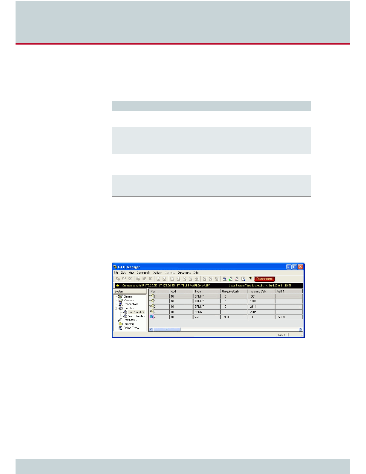
This chapter gives an overview to the GATE Manager. The GATE Manager will be used to
transfer and activate configuration files for the VoIPBox DSL / VoIPBox BRI. In addition the
GATE Manager allows to monitor the VoIPBox DSL / VoIPBox BRI.
The GATE Manager administration and maintenance software offers a broad range of functions. The GATE Manager is user friendly and can be customized to suit your needs.
Figure 4.4 GATE Manager
VoIPBox DSL / VoIPBox BRI – version:20.0.005
Page 22
Page 23

4 VoIPBox installation
The following maintenance functions are possible:
Display system information and network element status.
Retrieve and display configuration files.
Restart network elements.
Use of a trace option for checking functions and fault diagnosis. Option to use an
external tool, e.g. to display and break down trace data.
Update the system software (firmware) and configuration tables.
Retrieve CDRs (Call Detail Records).
Display the current connections (status).
Display statistical information for network elements and interfaces.
Display the status of the interfaces.
To complete the configuration retrieve and edit the config files as described in Chapter 5 on
page 30. You have to use GATE Manager version 20.0 or later. For a detailed description of
installation and implementation of the GATE Manager, please refer to the GATE Manager and
Utilities Programs Manual.
4.9 Transfer the config file with the GATE Manager to the PC
1. Open the TELES support page in a Web browser at http://195.4.12.8/agw/.
2. Download the GATE Manager.
3. Extract the archive and install the GATE Manager.
4. Follow the installation instructions.
5. Start the GATE Manager.
6. Add the VoIPBox DSL / VoIPBox BRI as new system to the default group:
–Select New System form the context menu (right mouse click to the main system
table).
– Insert in the dialog Edit Sytem a System name to identifiy the VoIPBox DSL /
VoIPBox BRI in the system table.
– Insert the IP address (default is 192.168.1.2) as Remote number and confirm
with OK.
7. Use the green Connect button from the tool bar to connect to the VoIPBox DSL /
VoIPBox BRI. No password is needed. Confirm the dialog with OK.
8. After connect select Directory in the left navigation bar.
9. The upper left rectangle shows the config files. There are three config files
pabx.cfg and routes.cfg.
10. Select one config-file after another and make a backup of these file using the context
menu Copy On System.
11. Select the context menu Edit to change the selectet config file. After editing the file
upload the file to the VoIPBox DSL / VoIPBox BRI.
ip.cfg,
4.10 Activate the DSL connection
The DSL configuration is stored in the file ip.cfg. This configuration is only needed on the
VoIPBox DSL. For the configuration the following information is needed from the DSL provider:
Username and password for DSL access.
DSL interface – DHCP, PPPoE, or a fix IP address. PPPoE is mainly used here.
There are some variants of additional DSL parameter:
– VLAN is used by the provider. The provider will send a VLAN tag if used.
– ATM is used by the provider. The provider will send the ATM cell address param-
– VLAN and ATM is used together – so configure a VLAN tag and the ATM param-
VoIPBox DSL / VoIPBox BRI – version:20.0.005
eter virtual path ID (Vpi) and virtual channel ID (Vci).
eter Vpi and Vci.
Page 23
Page 24

4 VoIPBox installation
Example 4.1 shows a
[dsl] section of the ip.cfg.
Example 4.1 [dsl] section of the ip.cfg
[dsl]
User="Heinz" # n
Pwd="123123123" # o
vlan=7 # p
Vpi=1
Vci=32
dslif=ppp # q
The username n used in Example 4.1 is
p used is
7. The Vpi and Vci parameters are also set to 1 and 32. The PPPoE interface q is
used for the DSL connection.
dslif is set to ppp as shown in Example 4.1, add an adition section [dslppp] as shown
If the
in Example 4.2 to the
ip.cfg.
Example 4.2 [dslppp] section of the ip.cfg
[dslppp]
lock
nodeflate
novj
novjccomp
nodetach
usepeerdns
defaultroute
lcp-echo-interval 10
lcp-echo-failure 10
debug
logfile /tmp/pppd.log
Heinz. The password o is 123123123. The VLAN ID
Example 4.3 shows a
[dsl] section of the ip.cfg with a fix IP assigned to the DSL interface.
Example 4.3 [dsl] section of the ip.cfg with fix IP address on dslif
[dsl]
User="Carl-Heinz" # n
Pwd="555666777" # o
dslif=10.1.2.151 netmask 255.255.255.0 # p
Dslroute= -net 0.0.0.0 gw 10.1.2.50 # q
The username n used in Example 4.3 is Carl-
Heinz. The password o is 555666777. The DSL
interface use a fix IP address p. For the fix IP address is set the default gateway 10.1.2.50 q.
Download the
ip.cfg configuration file from the VoIPBox DSL / VoIPBox BRI. Change the file
with a text editor for example notepad++ (http://notepad-plus-plus.org/). Upload the config
file to the VoIPBox DSL / VoIPBox BRI (Upload to System) and reboot the VoIPBox DSL.
VoIPBox DSL / VoIPBox BRI – version:20.0.005
Page 24
Page 25

4 VoIPBox installation
4.11 Activate the VoIP interface
The VoIP configuration is stored in the file route.cfg. The following settings are needed
from the VoIP provider:
The IP address of the SIP server.
User name and password for the SIP account.
Sometimes a registrar setup is needed.
Table 4.2 shows the configuration for the VoIP interface. The confguration is divided in to
three parts:
1. The call routing for calls from the VoIP carrier to the VoIPBox BRI and the calls from
the VoIPBox BRI to the VoIP carrier. In this example only one VoIP carrier (PeerA) is
used.
2. The SIP profile with the name PeerA containing username, password and IP address
of the remote SIP server. In addition it is possible to define a link to a registrar profile
in the VoIP profile.
3. The VoIPBox DSL / VoIPBox BRI registers on a Registrar with the information set in the
Registrar profile. Here is also a user name and password, an IP address of the Registrar and a own user ID (the own telephone number) needed. The registrar makes the
VoIPBox DSL / VoIPBox BRI for other SIP user visible and reachable.
Table 4.2 VoIP configuration in a route.cfg
[System]
DTMFWaitDial=3
Restrict40=Ix
#MapAllIx0049<LAC>=$Iy ; <LAC> is the local area code e.g. 30 for Berlin
#MapAllIx<LAC>=$Iy
MapAllIx=$Iy
MapAllIy=10s
MapAll00=40PeerA:00
MapAll0=40PeerA:0049
MapAll.=40PeerA:?
;;; SIP profile
;;; --------------------[Voip:PeerA]
VoipDirection=IO
VoipPeerAddress= ;; ip address:port e.g. 1.2.3.4:5060
VoipIpMask=0xffffffff
VoipSignalling=1
VoipUser=
VoipPwd=
;VoipOwnAddress= ; optional
VoipRegistrar=rega
VoipMaxChan=4
VoipCompression=g711a g711u g729a g729b
[Registrar:rega]
RegId= ;; ip address:port e.g. 1.2.3.4:5060
[email protected]
RegUser=
RegPwd=
RegSignalling=1
For a test call from the VoIPBox BRI to a B party in a national or international telphone network fill out the settings (
connect a telephone to the VoIPBox BRI and dial the number of the B party.
VoIPBox DSL / VoIPBox BRI – version:20.0.005
VoipPeerAddress, VoipUser, and VoipPwd) from the SIP profile,
Page 25
Page 26

4 VoIPBox installation
Next set the registrar settings so that the VoIPBox DSL / VoIPBox BRI is reachable for calls from
the VoIP network.
the port number.
RegId contains the IP or hostname of the registrar followed by a colon on
RegOwnId typically contains your host name or telephone number followed
by an @ sign and a domain name or IP address. Set user name and password as
RegPwd.
The default mapping sends all calls from the VoIP ports to the BRI ports and all calls from the
BRI ports to VoIP. This works with the default settings if a PBX is connected to the
VoIPBox DSL / VoIPBox BRI.
4.12 Changing the IP settings and/or deactivate DHCP
Changing the IP settings is necesarry if another DHCP server is active on the network or if another IP configuration is needed. The following information is needed:
DHCP on or off? The range of IP addresses used for DHCP.
IP address and netmask for the
If needed set a default gateway and a DNS server for the VoIPBox DSL / VoIPBox BRI.
Example 4.4 shows the required sections for the IP configuration of the VoIPBox DSL.
Example 4.4 Main sections of the ip.cfg
[system] # n
Hostname=TAG98313460700000
[br0] or the [eth1]/[eth2] interfaces.
RegUser and
[br0] # o
IpAddress=192.168.1.2 netmask 255.255.255.0
[dsl] # p
Vpi=0
Vci=33
vlan=106
dslif=ppp
User=dsluser
Pwd=password
[dslppp] # q
lock
nodeflate
novj
novjccomp
nodetach
usepeerdns
defaultroute
lcp-echo-interval 10
lcp-echo-failure 10
debug
logfile /tmp/pppd.log
[iptables] # r
iptables -t nat -A POSTROUTING -o ppp0 -s 192.168.1.2 netmask 255.255.255.0 -j
MASQUERADE
iptables -P INPUT DROP
iptables -P FORWARD DROP
iptables -P OUTPUT ACCEPT
iptables -A INPUT -s 0.0.0.0/0 -p tcp --dport 4445 -i ppp0 -j ACCEPT
iptables -N block
iptables -A block -m state --state ESTABLISHED,RELATED -j ACCEPT
iptables -A block -m state --state NEW -i ! ppp0 -j ACCEPT
iptables -A block -m limit -j LOG
iptables -A block -j DROP
iptables -A INPUT -j block
iptables -A FORWARD -j block
VoIPBox DSL / VoIPBox BRI – version:20.0.005
Page 26
Page 27

4 VoIPBox installation
Example 4.4 Main sections of the ip.cfg (continued)
#[dnsmasq] # s
#bogus-priv
#filterwin2k
#user=root
#interface=br0
#domain=teles
#dhcp-range=192.168.1.50,192.168.1.90,12h
#cache-size=150
#resolv-file=/etc/resolv.conf
[httpd] # t
PwdUser=dc1556f3cebe9e7d5da7e956f1c398c2
PwdAdmin=b4e3d44911fb4ad0d3af9fd2b4db94e4
Md5=yes
CmdExpected=0
UndoLastChanges=1
;*END CONFIG*
The hostname n is set here to the serial number “TAG98313460700000”. The IP address is
set to 192.168.1.2/24 o. That is the default. If you change the IP address don’t forget to
change the dhcp-range s and NAT r settings to. The DSL interface PPPoIP is used (p), so
the section
The firewall is active. All incoming traffic except the GATE Manager port 4445 is blocked.
Outgoing traffic is allowed r.
If DHCP is not needed comment out s the section with # as shown in Example 4.4.
The Web GUI is active t.
Example 4.5 shows a part from the
[dslppp] is also set in the configuration q.
ip.cfg with differnt settings for every IP interface.
Example 4.5 Different IP settings for every interface configured in the ip.cfg
[system]
Hostname=TAG98313460700068
DefaultGw=172.20.0.78
[Eth1]
IpAddress=172.20.27.224 netmask 255.255.0.0
[Eth2]
IpAddress=192.168.1.24 netmask 255.255.255.0
4.13 Remote access security
This chapter describes the settings for the remote access and Web GUI passwords.
4.13.1 Graphical User Interface
Remote access is possible via the Web GUI. Even users with little experience can easily configure standard system settings with this interface. Simply open a browser and enter the system’s IP address in the address bar.
The following administrative levels apply:
Administrator Mode (Full Access)
teles-admin
User:
Password: tcs-admin
VoIPBox DSL / VoIPBox BRI – version:20.0.005
Page 27
Page 28

4 VoIPBox installation
This access level is for the user network’s administrator. All configuration pages can be accessed in this mode.
Read-Only Mode
User:
teles-user
Password: tcs-user
No configuration changes can be made at this level. Only status and statistics can be retrieved.
The passwords are saved in the
PwdAdmin=<crypt>
PwdUser=<crypt>
Example 4.6 shows an ip.cfg entry.
ip.cfg in encrypted form:
Example 4.6
i
i
ip.cfg web gui section
[httpd]
PwdUser=dc1556f3cebe9e7d5da7e956f1c398c2
PwdAdmin=b4e3d44911fb4ad0d3af9fd2b4db94e4
Md5=yes
CmdExpected=0
UndoLastChanges=1
Never edit these entries. Use the GUI to change the password.
Enter the IP address of the VoIPBox DSL / VoIPBox BRI in the Web browser to start the GUI.
The user interface is divided into the following main sections:
Table 4.3 GUI: Sections
Section Description
User Data Here you can change the user passwords and the language for the HTTP in-
System Settings IP Settings:Settings for the Ethernet interfaces and related services.
System Overview Overview of system information and drivers.
Commands Here you can activate a configuration or restart the system.
All of the user interface’s pages contain Help buttons and links to the online help, which provides a detailed description of all of the individual configuration settings.
terface.
4.13.2 Setting a Password for Remote Access
The system comes with no password set for GATE Manager access. If you do not define a
password, access to the system via GATE Manager takes place without one, and FTP access
takes place with the default password
The password is set with the parameter
value <password> contains the encrypted text of the password.
Define the encrypted text with the GATE Manager as follows:
1. Open the GATE Manager,
2. Select the menu Edit | Encode Password…
VoIPBox DSL / VoIPBox BRI – version:20.0.005
tcs-ag.
RemotePassword=<password> in the pabx.cfg. The
Page 28
Page 29

4 VoIPBox installation
3. Enter the password in clear text in the Encode Password box and click OK.
4. In the screenshot above, the clear text password is
encoded password is
vDLGTEBIZUNDMR@fNP54B.
5. Enter the encoded password as shown in Example 4.7.
Example 4.7 pabx.cfg with an encoded password
RemotePassword=vDLGTEBIZUNDMR@fNP54B
Transfer the
pabx.cfg to the system using the GATE Manager. After the file has been trans-
ferred, reboot the system. The system can only be accessed with the correct password. Don’t
forget it!
4.13.3 Adjust the firewall settings
In the firewall on the PPP interface is open for incoming TCP traffic on port 4445 with the
following rule
iptables -A INPUT -s 0.0.0.0/0 -p tcp --dport 4445 -i ppp0 -j ACCEPT
Adjust the rule so that the access is possible only from a limited IP range. To do so replace
0.0.0.0/0 e.g. with 192.4.13.0/24.
Weihnachtsmann@Bln108. The
VoIPBox DSL / VoIPBox BRI – version:20.0.005
Page 29
Page 30

5 Configuration files
Page 31

5 Configuration files
This chapter describes the basic setup and the most commonly used entries for the
configuration files. Configuration of VoIPBoxes is managed in the following three
files:
Table 5.1 Configuration Files
File Function
ip.cfg
pabx.cfg
route.cfg
Changing configuration data may lead to malfunctions and/or misrouting, as well as possible
consequential damage. All changes are made at own risk. TELES is not liable for any damage
i
i
caused by or in relation to such changes. Please thoroughly check any changes you or a third
party have made to your configuration.
The default configuration with the IP address 192.168.1.2 is active after delivery. You can
configure the system using the GATE Manager.
Make sure you secure the system with new passwords following configuration and remember
to memorize the passwords (see Chapter 4.13 on page 27)!
These configuration files contain all system-specific settings and are used when the system
starts. Comments included in these files must begin with a semicolon. Comments can also be
placed at the end of the code line. Configuration files must end with an empty line.
The configuration files follow these conventions: Individual files are divided into sections.
These sections always begin with a line entry in square brackets. The basic required sections
in these files are:
This file is for the basic configuration of the Ethernet interfaces.
This file is for system-specific and port-specific settings.
This file is for routing and VoIP entries.
Table 5.2 Required Configuration File Sections
Section File Function
[System]
[Night<num>]
EXAMPLE: [Night1]
[br0] ip.cfg This section contains the IP configuration for the
pabx.cfg
route.cfg
ip.cfg
pabx.cfg
route.cfg
[Night2]
This section contains the system’s basic settings.
This section contains time dependent entries that
only apply for limited times.
Ethernet bridge of both Ethernet interfaces.
VoIPBox DSL / VoIPBox BRI – version:20.0.005
Page 31
Page 32

5 Configuration files
5.1 Configuration file ip.cfg
The basic settings for the two Ethernet interfaces are entered here. Generally, these settings
are entered once and then left unchanged.
This file contains the following sections, which must appear in the order given:
Table 5.3 Sections in the
Section Function
[System] (required) This section contains entries that define the default gateway and/or spe-
[br0] (required) The Ethernet controller section define the Ethernet bridge.
[eth1] and [eth2]
(instead of
[httpd]
[dsl] (optional) These section contains settings for DSL interface.
[dslppp] Thes section contains settings for the PPP interface used for the DSL con-
[iptables] This section contains settings for NAT and the system’s firewall.
[dnsmasq] This section enables the DHCP server the appropriate settings.
ip.cfg File
[br0])
5.1.1 System section configuration
The [System] section contains entries that define the default gateway and/or special routing
entries. To define the standard gateway, use the following entry to set the IP address:
DefaultGw=<ip addr>
cial routing entries.
The Ethernet controller sections – to define every Ethernet interface separatly. These sections can be used alternative to the bridge section
[br0].
This section contains the port and access password parameters for the
graphical user interface.
nection.
Example 5.1 Default gateway configuration
[System]
DefaultGw=192.168.1.254
If you must route specific net ranges to gateways other than what is defined in the default
route, make the following entries in the [System] section:
Route= -net <target ip> -netmask <net mask> gw <ip gateway> [dev <device>]
Example 5.2 Routing specific net ranges
[System]
DefaultGw=192.168.1.254
Route= -net 10.0.0.0 -netmask 255.0.0.0 gw 192.168.1.1 dev br0
If only certain routes apply, leave the line DefaultGw empty.
VoIPBox DSL / VoIPBox BRI – version:20.0.005
Page 32
Page 33

5 Configuration files
5.1.2 Ethernet interface configuration
The following settings are possible for the sections [br0] or [eth1] and [eth2]:
IpAddress=<ip addr> netmask <netmask>
The IP address is entered in decimal notation, followed by a slash (/) and the netmask in decimal notation.
Example 5.3 IP address configuration
IpAddress=192.168.1.2 netmask 255.255.255.0
Take a decision: Use a bridge with both interfaces [br0] or each interface separatly ([eth1]
and
i
i
5.1.3 GUI settings
[eth2]) with different IP settings. Britdge and single interface configuration together is
not possible.
The following parameter is used to change the GUI port in the section [httpd] (default 80):
GuiPort=<num>
Bear in mind that the passwords for different access levels are not set here. The encrypted
passwords are stored here and can only be changed via GUI (see Chapter 4.13.1 Graphical
User Interface).
Example 5.4 GUI configuration
[httpd]
GuiPort=80
PwdUser=dc1556f3cebe9e7d5da7e956f1c398c2
PwdAdmin=b4e3d44911fb4ad0d3af9fd2b4db94e4
5.1.4 DSL configuration
The DSL configuration is described in Chapter 4.10 on page 23.
5.1.5 Firewall configuration
If the VoIPBox DSL / VoIPBox BRI is running in a DMZ (Demilitarized zone (computing)) the
firewall must be activated in the
The firewall used on VoIPBox DSL / VoIPBox BRI is iptables. The documentation is freely available on the internet. Only the table filter is used in the
unless otherwise specified. Incoming and forwarded traffic is dropped unless otherwise specified.
ip.cfg (see Chapter 2.2.15 on page -16).
ip.cfg. Outgoing traffic is allowed
VoIPBox DSL / VoIPBox BRI – version:20.0.005
Page 33
Page 34

5 Configuration files
The options used in Example 5.5 are listed in Table 5.4.
Table 5.4 iptable options used in Example 5.5
Option Description
-P INPUT DROP Policy for the chain (INPUT, OUTPUT, FORWARD) used if no other filter rule
-A INPUT Policy added to the INPUT chain.
-d <destination IP> This policy is only true for packets with the given destination IP address.
-s <source IP> This policy is only true for packets from the given source IP address.
-i <interface> This policy is only true for packages used the given IP interface. (lo – local
-p <protocol> This policy is only true for the given IP protocol (UDP, TCP).
--dport <portnum> This policy is only true for the given protocol number. Sometimes the defini-
-j ACCEPT Defines the action that is carried out if the packet matches the rule.
is defined. The action used in this case is DROP. For the other rules, use the
action ACCEPT.
This option is not used in the example but if the source is known use this option for more security.
loop interface, ppp0 – the first IP interface)
tion in /etc/protocols will be used instead. This option can only be used
together with the -p option.
Example 5.5 shows the firewall rules activated in the ip.cfg.
Example 5.5 Basic firewall settings for ppp0
[iptables]
iptables -P INPUT DROP
iptables -P FORWARD DROP
iptables -P OUTPUT ACCEPT
iptables -A INPUT -d 127.0.0.1 -j ACCEPT
iptables -A INPUT -p icmp --icmp-type echo-request -j ACCEPT
iptables -A INPUT -p icmp --icmp-type echo-reply -j ACCEPT
; iptables -A INPUT -p tcp -i ppp0 --dport ftp -j ACCEPT
; iptables -A INPUT -p tcp -i ppp0 --dport http -j ACCEPT
; iptables -A INPUT -p tcp -i ppp0 --dport smtp -j ACCEPT
iptables -A INPUT -p udp -i ppp0 --dport 53 -j ACCEPT ; DNS forward
iptables -A INPUT -p udp -i ppp0 --dport ntp -j ACCEPT
; iptables -A INPUT -p udp -i ppp0 --dport snmp -j ACCEPT
iptables -A INPUT -p udp -i ppp0 --dport 1719 -j ACCEPT ; H.225 (UDP)
iptables -A INPUT -p tcp -i ppp0 --dport 1720 -j ACCEPT ; H.225 (TCP)
iptables -A INPUT -p tcp -i ppp0 --dport 4445 -j ACCEPT ; GATE Manager
iptables -A INPUT -p udp -i ppp0 --dport 5060 -j ACCEPT ; SIP
iptables -A INPUT -p udp -i ppp0 --dport 29000-29120 -j ACCEPT ; RTP
With these rules, outgoing traffic is allowed, incoming traffic is only possible in the local interfaces. The following protocols are allowed for incoming traffic: icmp (ping), DNS forwarding, NTP, H.225, SIP, and RTP (used for VoIP), and GATE Manager.
VoIPBox DSL / VoIPBox BRI – version:20.0.005
Page 34
Page 35

5 Configuration files
5.1.6 PPPoE Configuration
The protocol Point-to-Point over Ethernet is used for DSL communication. This means the system can connect directly to the carrier network and terminate VoIP traffic directly. Changes
in this section are not needed. All necessary information for setup of the PPPoE connection is
defined in the
[dslppp]
lock
nodeflate
novj
novjccomp
nodetach
usepeerdns
defaultroute
lcp-echo-interval 10
lcp-echo-failure 10
debug
logfile /tmp/pppd.log
5.1.7 DHCP and DNSmasq settings
The DHCP (Dynamic Host Configuration Protocol) server provides a mechanism for allocation
of an IP address and default gateway, to client hosts. Dnsmasq is an easy to configure DNS
forwarder. It is designed to provide DNS to a small network.
The section
system. Example 5.6 shows a
[dslppp] section. The following example shows a [dslppp] section.
[dnsmasq] contains a list of parameters and settings for the DHCP server in the
[dnsmasq] section.
Example 5.6 A [dnsmasq] section with DHCP and DNSmasq parameter
[densmasq]
bogus-priv
filterwin2k
user=root
interface=br0
domain=teles
dhcp-range=192.168.1.50,192.168.1.90,12h
cache-size=150
resolv-file=/etc/resolv.conf
DHCP is useful on the VoIPBox DSL.
i
i
VoIPBox DSL / VoIPBox BRI – version:20.0.005
Page 35
Page 36

5 Configuration files
The content of this section is described in Table 5.5.
Table 5.5 Parameter of the
Parameter Description
bogus-priv Bogus private reverse lookups. All reverse lookups for private IP
filterwin2k Later versions of windows make periodic DNS requests which
user=<username> Specify the userid <username> to which dnsmasq will change
interface=<if> Defines the network interface the DHCP and DNSmasq server is
cache-size=<cache> Set the size of dnsmasq's cache. The default is 150 names. Set-
domain=<domain> Defines the domain name <domain> used in the network.
dhcp-range=<f>,<l>,<d> The DHCP network range is defined by the first <f> and last <l>
resolve-file=<file> This file contains the name server assigned to the DHCP clients.
[dnsmasq] section
ranges (ie 192.168.x.x, etc) which are not found in /etc/hosts or
the DHCP leases file are answered with "no such domain" rather than being forwarded upstream.
don't get sensible answers from the public DNS and can cause
problems by triggering dial-on-demand links. This flag turns on
an option to filter such requests. The requests blocked are for
records of types SOA and SRV, and type ANY where the requested name has underscores, to catch LDAP requests.
after startup. Dnsmasq must normally be started as root, but it
will drop root privileges after startup by changing id to another
user. Normally this user is "nobody" but that can be over-ridden
with this switch.
bind on.
ting the cache size to zero disables caching.
address in the range. Client assignment begins with the last address. Duration <d> gives the time in houres the assigned address to the DHCP client is valid.
5.2 Configuration File pabx.cfg
The pabx.cfg is divided into the [System] section and the optional [Night<num>], [Mail]
and [Snmpd] sections.
5.2.1 System Settings
The [System] section is divided into several categories to ensure clarity:
VoIPBox DSL / VoIPBox BRI name
Log files
Global Settings
Controllers
Subscribers
Night configuration
VoIPBox DSL / VoIPBox BRI – version:20.0.005
Page 36
Page 37

5 Configuration files
5.2.1.1 VoIPBox DSL / VoIPBox BRI name
The variable
PabxName defines the name of the VoIPBox DSL / VoIPBox BRI in the GATE Man-
ager.
5.2.1.2 Log Files
CDRs, unconnected calls, system events, trace output and statistics can be saved into files.
The following entries are necessary to generate log files:
Table 5.6
pabx.cfg: Log File Entries
Entry Description
ActionLog=/boot/protocol.log
Log=/boot/cdr.log
Failedlog=/boot/failed.log
TraceLog=/boot/trace.log
You can define how the log files are to be divided. There are two possiblities for saving entries
into a new file:
In increments of time (twice-daily, daily, weekly, monthly)
Depending on the size of the file
You can also define a maximum number of up to 7 files to be generated.
-) appears in place of information that is to be ignored.
A dash (
Table 5.7 pabx.cfg: Log Parameters
System events
CDR entries
Unconnected calls
System trace
Log=/boot/<file> <saved> <size> <count>
<file>
<saved>
<size>
<count>
The name of the log file is generated as follows:
[file]yymmdd[0-9|A-Z].log.
Refers to the frequency with which the file is saved. The following options are
possible:
halfdaily Every day at 11:59 and 23:59
daily Every day at 23:59
weekly Sunday at 23:59
monthly The last day of the month at 23:59
Regardless of the value entered in <day>, the file will be saved when the <size>
has been reached (in kB).
NOTE: We recommend a file size of a multiple of 60kB.
Refers to the number of files that will be saved in the system (between 5 and
35) before the first file is overwritten. This setting is useful not only for limited
file size, but also for files that store events. Normally size can be limited for these
files, e.g. 5 files of 1MB each. If the fifth file is full, the first one will automatically
be overwritten.
Bear in mind that file size will be unlimited if no parameters are defined.
i
Please remember to keep track of how much memory is available on the system using the
i
command
df.
VoIPBox DSL / VoIPBox BRI – version:20.0.005
Page 37
Page 38

5 Configuration files
In the following entry, the file
cdr.log is renamed ev ery day. Up to 35 CDR files wil l be saved
on the system.
Example 5.7
cdr.log renamed daily
Log=/boot/cdr.log daily - 35
In the following entry, the file
failed.log is renamed once a week. Up to 10 failed files will
be saved on the system.
Example 5.8 failed.log renamed once a week
failedlog=/boot/failed.log weekly - 10
In the following entry, the file
protocol.log is renamed when the file has reached 1MB. Up
to five log files will be saved on the system.
Example 5.9 protocol.log renamed when file size = 1MB
ActionLog=/boot/protocol.log - 1000 5
VoIPBox DSL / VoIPBox BRI – version:20.0.005
Page 38
Page 39

5 Configuration files
5.2.1.3 NTP settings
The following settings for the network time protocol (NTP) are placed below the log settings.
NTP is used to clock synchronization over the IP network. Table 5.8 describes the parameter
used for this configuration.
There is no internal time generation for the system when the power is interrupted. This means
the default time is used when the system is restarted or rebooted!
i
i
Therefore it is important to set the system time with an NTP server.
If the system is connected via ISDN, a clock may come from the network connected to the corresponding port. Enter
time from the port.
Table 5.8 Parameter used for NTP settings
Parameter Description
NameServer=<dnsserver> Defines the IP address of the used domain name server. Enter
NtpServer=<nserver> Define the IP or name of the VoIPBox’s NTP server <nserver>
Ntprepeat=<time> Define the time in seconds the NTP query occures.
Timezone=<tz> Defines the timezone settings (see Table 5.9 on page 39).
TIME in the pabx.cfg’s Subscriber line for the TE port to take the
your network or ISP’s DNS server. If you don’t know it, you can
also enter another DNS server. If you have more than one address, enter this parameter up to three times on different lines.
This parameter must be set if you use for the NTP server a domain name.
queries the standard time.
NOTE: If your system is not attached to an NTP server, you can
enter the following configuration to query the time on an attached PBX via a TE port:
SubscriberXX=...TIME
Table 5.9 Timezone settings for different locations (page 1 of 3)
Continent To w n Settings
Australia Melbourne,Canber-
ra,Sydney
Perth WST-8
Brisbane EST-10
Adelaide CST-9:30CDT-10:30,M10.5.0/02:00:00,M3.5.0/
Darwin CST-9:30
Hobart EST-10EDT-11,M10.1.0/02:00:00,M3.5.0/03:00:00
EST-10EDT-11,M10.5.0/02:00:00,M3.5.0/03:00:00
03:00:00
VoIPBox DSL / VoIPBox BRI – version:20.0.005
Page 39
Page 40

5 Configuration files
Table 5.9 Timezone settings for different locations (page 2 of 3)
Continent To w n Settings
Europe Amsterdam, Netherlands CET-1CEST-2,M3.5.0/02:00:00,M10.5.0/03:00:00
Athens, Greece EET-2EEST-3,M3.5.0/03:00:00,M10.5.0/04:00:00
Barcelona, Spain CET-1CEST-2,M3.5.0/02:00:00,M10.5.0/03:00:00
Berlin, Germany CET-1CEST-2,M3.5.0/02:00:00,M10.5.0/03:00:00
Brussels, Belgium CET-1CEST-2,M3.5.0/02:00:00,M10.5.0/03:00:00
Budapest, Hungary CET-1CEST-2,M3.5.0/02:00:00,M10.5.0/03:00:00
Copenhagen, Denmark CET-1CEST-2,M3.5.0/02:00:00,M10.5.0/03:00:00
Dublin, Ireland GMT+0IST-1,M3.5.0/01:00:00,M10.5.0/02:00:00
Geneva, Switzerland CET-1CEST-2,M3.5.0/02:00:00,M10.5.0/03:00:00
Helsinki, Finland EET-2EEST-3,M3.5.0/03:00:00,M10.5.0/04:00:00
Kyiv, Ukraine EET-2EEST,M3.5.0/3,M10.5.0/4
Lisbon, Portugal WET-0WEST-1,M3.5.0/01:00:00,M10.5.0/02:00:00
London, Great Britain GMT+0BST-1,M3.5.0/01:00:00,M10.5.0/02:00:00
Madrid, Spain CET-1CEST-2,M3.5.0/02:00:00,M10.5.0/03:00:00
Oslo, Norway CET-1CEST-2,M3.5.0/02:00:00,M10.5.0/03:00:00
Paris, France CET-1CEST-2,M3.5.0/02:00:00,M10.5.0/03:00:00
Prague, Czech Republic CET-1CEST-2,M3.5.0/02:00:00,M10.5.0/03:00:00
Roma, Italy CET-1CEST-2,M3.5.0/02:00:00,M10.5.0/03:00:00
Moscow, Russia MSK-3MSD,M3.5.0/2,M10.5.0/3
St.Petersburg, Russia MST-3MDT,M3.5.0/2,M10.5.0/3
Stockholm, Sweden CET-1CEST-2,M3.5.0/02:00:00,M10.5.0/03:00:00
Tallinn, Estonia EET-2EEST-3,M3.5.0/03:00:00,M10.5.0/04:00:00
New Zealand Auckland, Wellington NZST-12NZDT-13,M10.1.0/02:00:00,M3.3.0/03:00:00
VoIPBox DSL / VoIPBox BRI – version:20.0.005
Page 40
Page 41

5 Configuration files
Table 5.9 Timezone settings for different locations (page 3 of 3)
Continent To w n Settings
USA / Cana-daHawaii Time HAW10
Alaska Time AKST9AKDT
Pacific Time PST8PDT
Mountain Time MST7MDT
Mountain Time (Arizona,
no DST)
Central Time CST6CDT
Eastern Time EST5EDT
Atlantic Time AST4ADT
Atlantic Time (New Brunswick)
Newfoundland Time NST+3:30NDT+2:30,M4.1.0/00:01:00,M10.5.0/
Asia Jakarta WIB-7
Singapore SGT-8
Ulaanbaatar, Mongolia ULAT-8ULAST,M3.5.0/2,M9.5.0/2
Central and
South America
Brazil, São Paulo BRST+3BRDT+2,M10.3.0,M2.3.0
Argentina UTC+3
Central America CST+6
MST7
AST4ADT,M4.1.0/00:01:00,M10.5.0/00:01:00
00:01:00
5.2.1.4 Controller settings
This category defines the parameters that apply to the ports.
The individual ports are defined with the following parameters. Ports set to the same type can
have the same address. In this case they will form a trunk group. If you change this parameter
in the configuration, you must restart the system. Table 5.10 list some settings for the controller parameter that may be used on the VoIPBox DSL / VoIPBox BRI.
Table 5.10 pabx.cfg: Controller Parameters
Controller<port>=<address> <type> <mode> <line_type> FCT UNIT:<unit> VALUE:<value>
AUTOUP TRAP
<port>
<address>
Defines the running (physical) port number.
Defines the configured (virtual) port address. In the default configuration, the BRI
TE port is 9, and the BRI NT port is 10. The VoIP port is 40.
VoIPBox DSL / VoIPBox BRI – version:20.0.005
Page 41
Page 42

5 Configuration files
Table 5.10 pabx.cfg: Controller Parameters (continued)
Controller<port>=<address> <type> <mode> <line_type> FCT UNIT:<unit> VALUE:<value>
AUTOUP TRAP
<type>
<mode>
<line_type>
UNIT:<unit>
VALUE:<value>
AUTOUP
TRAP
Defines the connection type:
TE external (Terminal Endpoint). Only the first controller can be set
NT internal (Network Termination). All NT ports must be configured
VOIP VoIP module with different codec support
VOIP SC VoIP software module that supports only G.711.
Defines the protocol for BRI lines: DSS1
Defines Point-to-Multipoint or Point-to-Point mode:
PMP Point-to-Multipoint
PP Point-to-Point
(Optional) Defines the currency for the charges (default EUR). Special charge generation is possilbe for:
Switzerland
NOTE: The <line_type> must be configured for these entries to work.
EXAMPLE:
Controller02=10 NT DSS1 PMP UNIT:€ VALUE:0.010
Controller03=10 NT DSS1 PMP UNIT:€ VALUE:0.010
(Optional) For DSS1 NT ports only. Defines the charges that accumulate by unit.
Enter the values in the following formats: x.y, x.yy, or x.yyy. Default is 0.120.
For TE-ports only: keeps ISDN layer 2 active all the time.
Sends an SNMP trap if layer 1 changes from active to inactive or from inactive to
active.
as TE.
together to the right of the TE ports.
UNIT:&CH
The following example applies for the VoIPBox BRI with 4 ISDN ports.
Example 5.10 VoIPBox BRI with 4 ISDN ports
Controller00=9 TE DSS1 PMP
Controller01=10 NT DSS1 PMP
Controller02=10 NT DSS1 PMP
Controller03=10 NT DSS1 PMP
Controller04=40 VOIP
5.2.1.5 Subscriber settings
Features for each port can be defined using this entry. Changes become active following a
restart Table 5.11 list some settings for the subscriber used for the VoIPBox DSL /
VoIPBox BRI..
You must restart the system after making changes to activate the settings.
i
i
VoIPBox DSL / VoIPBox BRI – version:20.0.005
Page 42
Page 43

5 Configuration files
Table 5.11
pabx.cfg: Subscriber Parameters
Subscriber<port>=<list>
<port>
The <list> variable may contain one or more of the following keywords:
TRANSPARENT ROUTER
ALARM
CHMAX[x]
5.2.2 SMTP-Client Configuration
The following entries in the pabx.cfg’s [Mail] section are used to send e-mail messages
from the VoIPBox. The connection to the SMTP server can be used to send CDR files or alarm
messages.
Refers to the running (physical) port number. The port of the controller.
Only the number is sent as caller ID (without the virtual port address).
Activate configuration suffices to activate changes. If TRANSPARENT
ROUTER is not set, the address of the incoming port is added to the A
party number as a prefix.
Activates the monitoring mode for the respective port. If a relevant error occurs at the port, the error is written in the protocol.log file. Depending on the configuration, a remote connection to the number
defined for AlarmCallback is established and/or an SNMP trap is generated. Activate configuration suffices to activate changes.
Defines the number of VoIP channels (8) or DTMF channels. A maximum of two concurrent channels are possible for DTMF recognition if
the callback platform is used.
You must restart the system after making changes to activate the settings.
i
i
The following features are possible:
Sending CDRs via e-mail
Sending alarm messages via e-mail
Table 5.12 pabx.cfg Mail parameters used in Example 5.11
Mail Parameters
MailAllowedPeers=<ip addr>
Defines IP addresses from which incoming SMTP connections will be accepted. Separate IP addresses with a space. If a dash (-) is entered, the SMTP port (25) will be blocked for incoming sessions. If this parameter is left empty (default), incoming connections will be accepted from all IP
addresses.
MailFrom=<URL>
Enter here the URL that will be sent in the e-mail’s FROM field in the following possible formats:
MailFrom=domain to send OAD@domain (or user@domain, if no OAD available).
MailFrom=ipaddress to send OAD@ipaddress (or user@ipaddress, if no OAD available).
MailFrom=123@ to send 123@<IP address of gateway>.
[email protected] to send [email protected].
MailFrom=123@ipaddress to send 123@ipaddress.
MailRcpt=<domain>
In <domain>, enter the destination domain, the destination address and an @ sign. If the destination address is already complete (with an @ sign),
<domain> is not added.
VoIPBox DSL / VoIPBox BRI – version:20.0.005
Page 43
Page 44

5 Configuration files
Table 5.12 pabx.cfg Mail parameters used in Example 5.11 (continued)
Mail Parameters
MailRcptMax=<count>
Number of "RCPT TO" entries in e-mails that come from the LAN (a message is sent to the LCR
for each "RCPT TO" entry in each incoming e-mail).
MailRcvMax=<count>
Maximum number of incoming e-mails queued for transmission via SMS or USSD.
MailSendRetries=<count>
Number of times an attempt is made to send an e-mail. Default 10.
MailToHostRetries=<count>
Number of retries when SMS transmission is not successful. When the limit entered is reached,
an error message is sent to the e-mail sender (default 3).
MaxMailsToHost=<count>
Maximum number of e-mail messages sent to the LCR simultaneously. Default 4.
SmtpServer=<ip addr>
In <ip addr>, enter the IP address of the destination SMTP server that is to receive the e-mail
messages.
Example 5.11 pabx.cfg Mail Parameters
[Mail]
SmtpServer=172.16.0.10
MailRcpt=teles.de
MailFrom=172.16.0.100
MailRcvMax=300
MailRcptMax=50
MaxMailsToHost=2
MailToHostRetries=10
MailSendRetries=10
MailAllowedPeers=172.16.0.10
Sending Alarm Messages via E-mail
With the appropriate configuration, you can send e-mails containing alarm messages that are
written into the log file. The sender is given as
subject box. The text box contains the alarm message.
The following entry in the configuration file activates this function.
Example 5.12 Sending Alarm Messages via E-mail
...
ActionLog=/data/protocol.log daily 1000 5 @<e-mail account>
...
alarm and the system’s name appears in the
VoIPBox DSL / VoIPBox BRI – version:20.0.005
Page 44
Page 45

5 Configuration files
5.2.3 SNMP Settings
The Simple Network Management Protocol facilitates network management and monitoring
of VoIPBox network devices and their functions. For a detailed description of SNMP configuration, please refer to Chapter 7.3 SNMP agent.
You must restart the system after making changes to activate the settings.
i
i
5.2.4 Night Configuration
The [Night<num>] section is reserved for prospective time-controlled configuration changes.
In the
pabx.cfg file, the Night sections contain all of the system’s Subscriber entries. Sim-
ply copy all
The sections for the time-dependent configuration changes and time-controlled routings are
defined here.
A maximum of 19 additional daily configuration zones are possible (
entry
tion.
The entry will have the following syntax:
Subscriber lines into the Night Section without making any changes.
NightResetTime reactivates the original configuration contained in the [System] sec-
Night1 to Night19). The
Table 5.13 pabx.cfg: Night Parameters
Night<num>=<time> <day>
<num>
<time>
<day>
The configuration section is activated Fridays, Wednesdays and Mondays at noon unless the
day in question is a holiday:
Example 5.13 Night parameters 1
Night2=12:00 00101010
The configuration section switches back to the default configuration (
ery day at 8:00 p.m:
Example 5.14 Night parameters 2
NightResetTime=20:00 11111111
Enter a value between 1 and 19 to define which configuration is to be loaded.
If there is a time set with the format hh:mm after this entry, this configuration
is loaded daily at that time on the defined day.
Use a bitmask to set the weekdays on which the configuration applies here.
The daymask appears in the following order:
HoSaFrThWeTuMoSu.
[System] section) ev-
VoIPBox DSL / VoIPBox BRI – version:20.0.005
Page 45
Page 46

5 Configuration files
The configuration section is activated on November 5, December 24, and at noon on Mondays.
Example 5.15 Night parameters 3
Night1=12:00 10000010
Holiday=05.11.
Holiday=24.12.
Holidays
Up to 50 different dates can be set for night sections used by holiday. The variable dd.mm
sets the day and month in which the night section is activated when the 8th bit is set in the
bitmask (see Table 5.13).
Any defined Night sections must be set in the files pabx.cfg and route.cfg. If there are no
changes in these sections, you must copy them from the
i
i
Subscriber section must appear in the Night section of the pabx.cfg. The active route(s)
(
MapAll, Restrict and Redirect entries) must appear in the Night section of the
route.cfg (see Chapter 5.3 Configuration File route.cfg).
[System] section. The complete
5.3 Configuration File route.cfg
The system’s routing information is saved in the route.cfg. The file contains the following
sections:
[System]
[Night<num>]
[VoIP=<name>]
[GateKeeper=<name>]
[Registrar=<name>]
[Radius=<name>]
5.3.1 Entries in the Sections [System] and [Night<num>]
The sections [System] and [Night<num>] contain the following entries.
5.3.1.1 Restrict
Restrict entries are used to handle calls in a mapping based on the controller / controller
group where the calls originate. A
coming from PSTN directly to the PBX.
Restrict parameter adds a prefix to a DAD before the DAD is mapped. Restrict pa-
The
rameters are always handled before the
MapAll parameter.
The left side of the equals sign in the
plus an optional trunk number or a specific calling number (OAD). The special symbol
be used as a wildcard to represent any character. The right side contains the prefix that is to
be put in front of the DAD and an optional service indicator.
Restrict entry can be used, for instance, to route all calls
MapAll parameters and always require a matching
Restrict parameter contains the controller number
? may
VoIPBox DSL / VoIPBox BRI – version:20.0.005
Page 46
Page 47

5 Configuration files
In the
route.cfg, the list of Restrict parameters is searched from bottom to top for a
matching controller plus optional trunk number / OAD. Because the search is done bottom
up, place the more specific
has been found, the DAD is prefixed with the contents of the
mapped.
Restrict entries below the more general ones. Once a match
<pl> variable. Then the call is
Table 5.14
route.cfg: Restrict Parameters
Restrict<controller><calling number>=<pl> <sin> |
RestrictD<diverting number>=<pl> 15
RestrictR<calling number>=<pl> 15
RestrictT<calling number>=<pl> 15
Parameter Description No. Digits Optional
<controller> Contains the controller number.
<calling number> Contains the calling number (OAD). The special
<pl> Stands for a virtual placeholder. The DAD is
<sin> The service indicator variable sin restricts the
D<diverting number> For calls that have been diverted by the net-
R<calling number> For calls that are redirected with Redirect3,
T<calling number> For calls that are redirected with Redirect2,
? may be used as a wildcard to repre-
symbol
sent any character.
prefixed with the contents of this variable.
command to one service. Without a
Restrict command is valid for all services.
Possible service indicator values are:
01 Telephony
02 Analog services
03 X.21-services
04 Telefax group 4
05 Videotext (64 kbps)
07 Data transfer 64 kbps
08 X.25-services
09 Teletext 64
10 Mixed mode
15 Used internally for calling-par-
ty manipulation
16 Video telephone
work, RestrictD replaces the contents in <diverting number> by the contents in <pl>. Only
in combination with the service indicator 15.
the original OAD can be changed again using
RestrictR. Only in combination with service
indicator 15.
the original OAD can be changed again using
RestrictT. Only in combination with service
indicator 15.
sin, the
59
59
2
59 for the
diverting
number
59 for the
calling
number
59 for the
calling
number
VoIPBox DSL / VoIPBox BRI – version:20.0.005
Page 47
Page 48

5 Configuration files
All calls coming from BRI controller 9 (PSTN) are sent to BRI controller 10 (PBX). First, the Restrict command adds the prefix “pl” to the DAD of the received call for all calls coming from
PSTN. Then the call is mapped. In the mapping, everything that is prefixed with “pl” is sent
to controller 10 by removing the prefix and adding the controller to the number.
Example 5.16
route.cfg Restrict Parameters
Restrict9=pl
MapAllpl=10
5.3.1.2 MapAll
Mapping entries are necessary for routing calls. The prefix or telephone number (DAD) for
which the mapping applies is searched and the call routed according to the matching mapping entry.
Mapping entries begin with the keyword
of the equals sign is removed from the prefix / telephone number (DAD) that has come in and
replaced with what is on the right of the equals sign.
If, for example, the incoming DAD is 12345678 with 123456 being the trunk number and 78
the extension,
MapAll123456=9123456 means that 123456 is cut off the number and
9123456 is added to it. The called number is 912345678 with 9 being the port.
MapAll123456=9 means that 123456 is cut off and 9 added. The called number is 978 with
9 being the port.
Mappings are searched from top to bottom. Place the more specific entries above the more
general ones.
Table 5.15 route.cfg: Map Parameters
MapAll<direct>=<num> <mode>
Parameter Description No. Digits Optional
<direct>
<num>
<mode>
MapAll. They work as follows: anything on the left
Defines the prefix or telephone number (DAD)
for which the entry applies.
Defines the routing for a call in the order given:
Destination port’s controller number
Optional VoIP profile name followed by a
colon if the call is terminated via VoIP
Optional prefix
Part of the number on the left that is trans-
mitted
The special symbol
to represent any character.
The special symbol
to represent any digit.
VOICE
DATA Applies for calls with the ser-
? may be used as a wildcard
. may be used as a wildcard
Applies for calls with the service indicator voice (default).
vice indicator data.
29
59
4 or 5 X
VoIPBox DSL / VoIPBox BRI – version:20.0.005
Page 48
Page 49

5 Configuration files
All international calls (DAD starts with 00) are sent to the VoIP controller 40 with the profile
name DF. 00 is removed from the DAD, 40DF:00 is added to it. All national calls (DAD starts
with 0) are sent to the controller with the number 9. It is important that the mapping for international calls is placed above the mapping for national calls. If you change the order of
both mappings, international calls would be sent to controller 9 instead of 40.
Example 5.17
route.cfg Map Parameters
MapAll00=40DF:00
MapAll0=90
5.3.1.3 Redirect
This entry facilitates alternative routing when the first destination cannot be reached or is
busy. A placeholder appears to the right of the equal sign. The routing entry (
defined for the redirect using the placeholder entered:
Table 5.16 route.cfg: Redirect Parameters
Redirect<type><num>=<redirect> <sin> <time>
Parameter Desription No. Digits Optional
<type>
<num>
<redirect>
<sin>
<time>
Enter 2 or 3 to set the following types:
2 call forwarding no answer
3 call forwarding when busy
Defines the number for which calls will be redirected.
The special symbol
resent any character.
Defines the placeholder used in the two-target routing
entry and the number to which calls to
rected.
The service indicator variable sin restricts the command
to a service. Without a
valid for all services.
Possible service indicator values are:
00 All services
01 Telephony
02 Analog services
03 X.21-services
04 Telefax group 4
05 Videotext (64 kbps)
07 Data transfer 64 kbps
08 X.25-services
09 Teletex 64
10 Mixed mode
15 Videotext (new standard)
16 Video telephone
NOTE: Fax forwarding must be set for analog and telephony services because incoming fax calls from the analog network may arrive with either telephony or analog
service indicators.
For type 2 redirect entries, a timer (in seconds) can be
defined after the service indicator entry.
? may be used as a wildcard to rep-
<x> will be redi-
sin, the Redirect command is
MapAll) can be
1
59
59
2 (X)
(Only optional if
<time> is
not set. If
<time> is
set and
<sin> is not
needed
please select 00 for
sin.)
255 X
VoIPBox DSL / VoIPBox BRI – version:20.0.005
Page 49
Page 50

5 Configuration files
In the following example all international calls (beginning with 00) are sent to VoIP controller
40 with the carrier profile DF. If the carrier cannot be reached or is busy, the redirect command activates the second target mapping with the placeholder A and the call is automatically sent to controller 9.
Example 5.18 Redirect 1
MapAll00=40DF:00
Redirect340DF:=A
MapAllA=9
In the following example, calls to 20 that remain unanswered for 12 seconds and calls to 21
that remain unanswered for 20 seconds are redirected through the PSTN port.
Example 5.19 Redirect 2
MapAll01555=|2001555<<13
MapAll01556=|2101556<<13
Redirect220=A 01 12
Redirect221=A 01 20
MapAllA=9
Excluding Busy Calls or Specific Cause Values from Redirect
Defines a hexadecimal cause value according to DSS1. When connections to the destination
are rejected because of the reason defined by the cause value, the VoIPBox sends a busy signal to the attached PBX. Alternative routing is not carried out.
To avoid second-choice routings when the called-party number is busy, set the following parameter in the first-choice port’s
BUSY[<cause>]
Subscriber line in the pabx.cfg:
This parameter defines a hexadecimal cause value according to DSS1. When connections to
the destination are rejected because of the reason defined by the cause value, the VoIPBox
sends a busy signal to the attached PBX. Alternative routing is not carried out. You can also
define a range of consecutive cause values:
BUSY[<cause>,<cause>].
An exclamation point (!) in front of a cause value means all cause values except the one listed.
For example,
BUSY[!95], means all cause values except 95 will be rejected with a busy signal.
In the following example, all outgoing calls over controller 04 are rejected with the cause value 91 when the called party is busy. Alternative routing is not carried out.
Subscriber04=....BUSY[91]
VoIPBox DSL / VoIPBox BRI – version:20.0.005
Page 50
Page 51

5 Configuration files
5.3.2 VoIP Profiles
This section includes all of the most important parameters for communication with the VoIP
peer.
Basic Parameters
Please refer to Chapter 8 Signaling and routing features for information on other possible en-
tries.
Table 5.17
route.cfg: VoIP Basic Parameters
VoIP Basic Parameters
[Voip=<name>]
Name of the routing profile. The name must begin with a letter. Choose a short and meaningful
name.
VoipDirection=<mode>
Defines the direction in which VoIP calls can be set up. Possible options: In, Out, IO, None).
VoipPeerAddress=<ip addr> or <name>
The peer’s IP address or name. Default is 0 (if it is not set, please set the parameter VoipIpMask
to 0x00000000).
VoipIpMask=<ip mask>
The subnetmask is used to determine the size of the IP address range for incoming traffic. The
0x followed by the mask in hexadecimal notation. Example of a Class C mask entry:
syntax is
0xffffff00. Default is 0xffffffff (only incoming traffic is accepted from the defined peer ad-
dress).
VoipSignalling=<int>
Determines the profile’s signaling protocol for outgoing VoIP calls. In the case of incoming calls,
autorecognition ensures that each call from the peer is accepted, regardless of the protocol:
0=H.323 (default), 1=SIP udp, 2=SIP tcp, 3=tls.
NOTE: TLS requires the following additional software: crypto.vnd and the key files key.pem and
cert.pem.
VoIPBox DSL / VoIPBox BRI – version:20.0.005
Page 51
Page 52

5 Configuration files
Table 5.17 route.cfg: VoIP Basic Parameters (continued)
VoIP Basic Parameters
VoipCompression=<list>
The compression to be used, in order of preference. At least one matching codec with the peer
must be defined.
Voice:
g729, g729a, g729b, g729ab
g72616, g72624, g72632, g72640
NOTE: G726 32kBit/s can also be signaled as G.721 by using the entry g721.
g728
g711a, g711u
g723, g723L
NOTE: This has no influence on the compression ratio of incoming RTP packets. Both sides must be
able to receive both ratios.
gsm
The following codecs are also possible: g721 (SIP only)
Fax: t38
Data: trp
gnx64
ccd
Define a special profile for data call origination or destination numbers. Bear in mind that echo
cancelation in this VoIP profile might be switched off (
VoipMaxChan=<count>
Maximum number of channels that can be used with the profile. If this parameter is not defined
(default), there will be no limit.
VoipSilenceSuppression=<mode>
Yes
tion).
NOTE: In SIP signaling, silence suppression is negotiated as per RFC3555.
VoipTxM=<num> or <list> fix
The multiplication factor (1-12) for the frame size for transmission of RTP packets (default is 4).
10ms is the default frame size. A list can be defined if different frame sizes are to be used for
different codecs in the VoIP profile. The list must correspond with the list in the parameter
Compression
Normally the peer’s frame size will be used if it is smaller than the one defined. If you enter
the configured factor will always be used.
These codecs have a bit rate of 8 kbit/s (compression ratio 1:8). A stands for annex
a and b for Annex b.
These ADPCM codecs have various bit rates: g72616 = 16kBit/s (compression ratio
1:4), g72624 = 24kBit/s, g72632 = 32kBit/s (compression ratio 1:2), and g72640 =
40kBit/s.
The Codec has a bit rate of 16kBit/s (compression ratio 1:4).
These PCM codecs have a bit rate of 64kBit/s. No voice compression occurs. a stands
for a-law and u for μ-law.
These codecs work with 30ms data frames. g723.1 uses a bit rate of 6.3 kbit/s, and
g723L uses a bit rate of 5.3 kbit/s to send RTP packets.
GSM-FR (full rate) has a bit rate of 13 kbit/s.
T.38 (fax over IP) allows the transfer of fax documents in real time between 2 fax machines over IP. Following fax detection during a call, the voice codec will switch to
T.38.
Transparent or clear mode (RFC 4040). Transparent relay of 64 kbit/s data streams.
Clear-channel signaling (as per RFC3108)
activates silence suppression, CNG (comfort noise generation) and VAD (voice activity detec-
No (default) deactivates silence suppression.
.
VoipECE=no).
Voip-
fix,
VoIPBox DSL / VoIPBox BRI – version:20.0.005
Page 52
Page 53

5 Configuration files
Management Parameters
Table 5.18
route.cfg: VoIP Management Parameters
VoIP Management Parameters
VoipGk=<list>
Name of the assigned gatekeeper profile. You can assign a profile to several gatekeepers to define
backup gatekeepers for a VoIP profile. In this case, the next gatekeeper will be used if the previous
one fails.
VoipProxy=<ip addr>
Enter the IP address of the SIP server.
VoipUser=<username>
Define the username for the remote device if authentication is required (SIP only).
VoipPwd=<password>
Define the password for the remote device if authentication is required (SIP only).
VoipRegistrar=<name>
Enter the name of a registrar to be used for the VoIP profile.
VoipRadiusAuthenticate=<name>
Enter the name of the Radius server to activate user authentication.
VoipRadiusAccounting=<name>
Enter the name of the Radius server to activate accounting.
VoipRadiusIMSINegotiation=<mode>
If yes is entered, the <system> will negotiate the IMSI to be used in the Radius access request. It
will transmit the IMSI in the RADIUS attribute: Filter-Id (11). Default no.
NOTE: The call number of the dial attempts must begin with the LAIN or the port number if CHADDR
is not used. The following routing entry must be added: MapAll*??01:<LAIN>=<LAIN>*??01:
VoipIpLogging=<mode>
Enter Yes to activate recording IP addresses in the CDRs (default is No). The first IP address is the
signaling address and the second is the RTP address, followed by the the codec and the frame
size used. The IMSI appears after the IP addresses.
Example of a CDR entry:
21.08.07-11:01:42,21.08.0711:01:58,40,912345,192.168.0.2:192.168.0.2,G729,10,0101,16,10,0
Example of a failed log entry:
21.08.07-11:11:30,40,91234,192.168.0.2:192.168.0.2,G729,10,0101,ff,2,1
VoipStatLogging=<mode>
When Yes is entered, statistic values (e.g. fraction lost, round trip time, etc.) for the VoIP profile
are saved into the protocol.log file every ten minutes. This is helpful during problem analysis when
IP issues occur (default =
VoipHold=<mode>
No).
Determines the behavior of the HOLD feature if a PBX sends an Re-INVITE message for HOLD to
the VoIPBox.
transparent: HOLD is sent to PSTN
notify: HOLD is sent as notification to the telephone exchange
ignore: HOLD is not sent to the telephone exchange - the VoIPBox suppresses the messages to
PSTN
VoipSelectProfilesBySignalling=<Yes/No>
When Yes is entered, VoipSignalling=<int> is taken as the criterion for selecting a voip-profile
for an incom-ing voip call, i.e. the signalling for this voip call must match the VoipSignalling parameter in this profile. Default
No.
VoIPBox DSL / VoIPBox BRI – version:20.0.005
Page 53
Page 54

5 Configuration files
5.3.3 Gatekeeper Profiles
Gatekeeper profiles are used to connect the VoIPBox to several systems by using a gatekeeper
if the protocol is H.323. It is possible to configure different gatekeepers for different destinations and to define backup gatekeepers. These gatekeeper profiles are then assigned to the
VoIP profiles:
Table 5.19
route.cfg: Gatekeeper Parameters
Gatekeeper Parameters
[Gatekeeper=<name>]
Name of the gatekeeper profile.
RasPort=<port>
Indicates the port the gatekeeper uses (default 1719) for registration, admission and status.
OwnRasPort=<port>
Indicates the port the system uses (default 1719) for registration, admission and status.
RasPrefix=<list>
VoIPBox’s defined prefix(es). Use a space to separate entries.
RasId=<name>
The alias used for gatekeeper registration.
GkId=<name>
The gatekeeper’s alias.
GkPwd=<name>
Password to log onto the gatekeeper. If you do not use authentication, leave this entry blank.
GkAdd=<ip addr>
The gatekeeper’s IP address.
GkTtl=<sec>
Gatekeeper time to live (default 0 means infinite).
GkMaxChan=<count>
Max. number of channels used for this gatekeeper. If this parameter is not defined (default), there
will be no limit.
GkUseStun=<mode>
Enter yes (default) to use the STUN values for the GK profile.
GkTerminalAliasWithPrefix=<mode>
Some gatekeepers may require that prefixes are listed in the Terminal Alias section. Enter Yes to
activate this function; default value is
GkTerminalTypeWithPrefix=<mode>
No).
Enter No to deactivate sending the Dialed Prefix Information in the Registration Request (default
Yes).
GkDynRai=<mode>
When yes is entered, the GK receives an RAI (resource availability indication) when a status
change occurs on the available mobile channels. When no is entered, the RAI is sent with each
ARQ (admission request) and DRQ (disengaged request). Default is no.
GkNoResourceAvailableIndication=<mode>
With this parameter the <system> will not send RAI indications to the Gatekeeper. Default No.
VoIPBox DSL / VoIPBox BRI – version:20.0.005
Page 54
Page 55

5 Configuration files
5.3.4 Registrar Profiles
Registrar profiles are used to register the VoIPBox with a SIP registrar. It is possible to configure different registrars for different destinations and to define backup registrars. These registrar profiles are then assigned to the VoIP profiles:
Table 5.20
route.cfg: Registrar Parameters
Registrar Parameters
[Registrar=<name>]
The name of the registrar profile.
RegId=<name or ip addr>
Host name or IP address used in the register’s request header. Bear in mind that the DNS service
must be active if you enter the host name.
RegOwnId=<name@ip addr/domain>
Typically a host name or telephone number followed by an @ sign and a domain name or IP address. The entry used in the
RegSameCallID=<mode>
From: field. The default setting is RegUser@RegId.
When Yes is set (default), the same caller ID is always used for SIP registration. Set No to change
the caller ID for each SIP registration.
RegContact=<name or ip addr>
Used in the Contact: field.
RegContactParam=<string>
Sets additional header-parameters in the contact field (e.g.the q-value: RegContactParam=q=1.0).
RegUser=<name>
Enter a username for authorization.
RegPwd=<password>
Enter a password for authorization.
RegProxy=<ip addr>
Enter an alternative IP address if you want the request to be sent to an address other than the
one entered in
RegExpires=<sec>
RegId.
Enter the number of seconds registration is to be valid. Default 0 means infinite.
RegPing=<sec>
Interval (in seconds) for the registrar ping. The VoIPBox sends an empty UDP packet to the registrar’s IP address. The packet is essentially an alive packet to avoid possible firewall problems.
RegSignalling=<int>
Determines the profile’s signaling protocol for registration with the SIP registrar.
1=SIP udp (default)
2=SIP tcp
3=SIP tls
RegUseReceived=<mode>
Enter Yes when an VoIPBox appears behind a NAT and STUN cannot be used. Default No.
RegSameCallID=<mode>
The same call ID is used for SIP registration Enter No to change the call ID for every reregistration.
(default Yes).
VoIPBox DSL / VoIPBox BRI – version:20.0.005
Page 55
Page 56

5 Configuration files
5.3.5 Radius Profiles
Radius profiles are used to connect the VoIPBox to a Radius server. You can use a Radius server for different destinations and for access and/or accounting. These Radius profiles are then
assigned to the VoIP profiles:
Table 5.21
route.cfg: Radius Parameters
Radius Parameters
[Radius=<name>]
The name of the Radius server profile assigned to one or more VoIP profiles.
Host=<name or ip addr>
Radius server’s host name or IP address. Bear in mind that the DNS service must be active if you
enter the host name.
User=<name>
Enter a username for authorization.
Password=<password>
Enter a password for authorization.
Secret=<secret>
Enter the shared secret.
OwnId=<name or ip addr>
Host name or IP address used in the NAS identifier or NAS IP address (Cisco VSA gateway ID).
ServiceType=<num>
As defined in RFC 2865, Chapter 5.6.
RequestTimeout=<sec>
Number of seconds during which the request is repeated if the Radius server does not respond.
RequestRetries=<count>
Number of packet retries sent at one time.
StopOnly=<mode>
When Yes is entered, only Accounting Request Messages with the status type stop are transmitted to the Radius server.
AlwaysConnected=<mode>
Enter No (default) to set the value for the field ConnectedTime to that of the field Disconnect-
in accounting-stop messages when the call was not connected.
edTime
CallingStationId=<num>
This parameter is used to set the calling station ID. The default setting is the OAD, but you can
define any calling station ID. To define a partial calling station ID, enter a
CallingStationId=??? will consist of the first three digits of the OAD.
ample,
CallType=<int>
? for each digit. For ex-
Enter one of the following to define the call type:
3 = VoIP and telephony
2 = VoIP only
1 = Telephony only
VoIPBox DSL / VoIPBox BRI – version:20.0.005
Page 56
Page 57

5 Configuration files
Table 5.21 route.cfg: Radius Parameters (continued)
Radius Parameters
FramedProtocol=<int>
Enter one of the following to define the framed protocol (see RFC 2865, Chapter 5.7):
1 = PPP
2 = SLIP
3 = AppleTalk Remote Access Protocol (ARAP)
4 = Gandalf proprietary SingleLink/MultiLink protocol
5 = Xylogics proprietary IPX/SLIP
6 = X.75 Synchronous
NasId=<string>
The string entered is used as network access server identifier attribute in access requests. If no
string is entered, the attribute will not be set (default).
VoIPBox DSL / VoIPBox BRI – version:20.0.005
Page 57
Page 58

6 Additional VoIP parameters
Page 59

6 Additional VoIP parameters
You can enter the following additional parameters in the
route.cfg to adjust the configu-
ration for improved communication with the VoIP peer.
6.1 Signaling parameters
Table 6.1 Customized parameters: protocol-independent VoIP signaling (page 1 of 4)
Protocol-Independent VoIP Signaling Parameters
VoipComprMaster=<mode>
This parameter defines which side the first matching codec comes from:
Yes: Default. Priority is determined by the order of the system’s parameter list.
No: Priority is determined by the peer.
VoipConnectOnCallProc=<mode>
Enter Yes (default No) to change an H.323 Call Proceeding/Call Progress and Alert, or a SIP 180
or 183, into an H.323 Connect or SIP 200 message. This parameter can be used if an announcement that plays before the Connect requires a Connect on the other side to put through the call.
VoipDad=<num>
The digits/numbers defined here will appear in front of the original DAD as described for the parameter VoipOad below. If the parameter is to be valid in only one direction, you must also set
the parameter VoipDadIn or VoipDadOut .
VoipDadIn=<string>
Specifies that the parameter VoipDad is for incoming calls only. If this parameter is not set (default), VoipDad will apply for both directions.
VoipDadOut=<string>
Specifies that the parameter VoipDad is for outgoing calls only. If this parameter is not set (default), VoipDad will apply for both directions.
VoipDataBypassPayloadType=<num>
Defines the payload type for the RTP packets when the call is sent as a data call. Default 96.
VoipEarlyT38=<mode>
Enter yes to enable T38 before the call has been connected. Enter no to enable T38 after the call
has been connected. Default yes.
VoipEarlyVP=<mode>
Activates the vocoder chip caused by an incoming SIP 180 or 183 without sdp. Fax tones coming
from ISDN are already recognized before the connect and can thus prepare or even allow a switch
to T38. Default
VoipG72616PayloadType=<num>
Changes the RTP payload type for G.726 16 b/s. Default is 35. A common alternative is one of
the dynamic payload types from 96 to 127.
VoipG72624PayloadType=<num>
Changes the RTP payload type for G.726 24 b/s. Default is 36. A common alternative is one of
the dynamic payload types from 96 to 127.
VoipG72632PayloadType=<num>
Changes the RTP payload type for G.726 32 b/s. Default is 2. A common alternative is one of the
dynamic payload types from 96 to 127.
VoipG72640PayloadType=<num>
Changes the RTP payload type for G.726 40 b/s. Default is 38. A common alternative is one of
the dynamic payload types from 96 to 127.
no.
VoIPBox DSL / VoIPBox BRI – version:20.0.005
Page 59
Page 60

6 Additional VoIP parameters
Table 6.1 Customized parameters: protocol-independent VoIP signaling (page 2 of 4)
Protocol-Independent VoIP Signaling Parameters
VoipHideOadByRemove=<mode>
If Yes is configured and call setup is to VoIP, the OAD will be removed from signaling if presentation restricted or user-provided, not screened is set in the calling party’s presentation or screening
indicator. No (default) means no change will occur.
NOTE: If the SIP protocol is used, Anonymous will always appear as the account in the From field.
Transmission of the OAD can occur in the P-asserted header.
VoipIgnoreDADType=<mode>
Enter yes to change the DAD type to unknown, for example from international. The type is lost, for
example the leading 00 bit is removed. Default no.
VoipLimit=<limit>
Limit with this parameter the total number of units that can be sent through the VoIP profile
where this parameter has been configured. If the limit has been reached, no further outgoing calls
are possible via this profile. The length of a unit in seconds is defined with VoipUnitPeriod. The
counter is reset using the ResetCounter parameter in the pabx.cfg file.
VoipOad=<num>
In the following examples, the OAD is 5175551212.
The digits/numbers defined here will be transmitted in front of the original OAD. In the following
example, 001 will appear in front of the number 5175551212.
EXAMPLE:
To transmit only OADs consisting of more digits than those defined, enter a !, followed by the
number of digits, at the end of the entry. If the OAD has more digits, it will be transmitted unchanged. If it has the same number or fewer digits, only the string in front of the ! will be added
in front of the OAD. In the following example, the digits 0015175551212 will appear::
EXAMPLE:
If a minus (-) is entered, the original OAD will not appear. In the following example, no number
will be transmitted.
EXAMPLE:
If integers are entered before the minus sign, only the digits entered in front of the minus sign
will be displayed. In the following example, 789 will appear.
EXAMPLE:
If an integer is entered after the minus sign, this number of digits will be removed from the be-
ginning of the OAD. In the following example, 517 will be removed from the OAD:
EXAMPLE:
If -\ is entered followed by the first part of an OAD, that part will be removed. If the string does
not match, the OAD will be transmitted unchanged. In the following example, only 1212 will be
transmitted.
EXAMPLE:
To modify the original OAD, enter random<x>, whereby x represents a number of random digits
between 1 and 10 that will appear in the OAD. In the following example, 001 plus 2 random digits
plus the original OAD will appear.
EXAMPLE:
If --\ is entered followed by a part of an OAD (not necessarily the first part), the OAD will not be
transmitted at all. If the string does not match, the OAD will be transmitted unchanged. In the
following example, the OAD is not transmitted.
EXAMPLE:
VoipOad=001
VoipOad=001!10
VoipOad=-
VoipOad=789-
VoipOad=-3
VoipOad=-\517555
VoipOad=001random2
VoipOad=--\555
VoIPBox DSL / VoIPBox BRI – version:20.0.005
Page 60
Page 61

6 Additional VoIP parameters
Table 6.1 Customized parameters: protocol-independent VoIP signaling (page 3 of 4)
Protocol-Independent VoIP Signaling Parameters
VoipOad=<num> (continued)
If -<num>-\ is entered followed by a part of an OAD (not necessarily the first part), the entered
number of digits is cut from the OAD and the remaining OAD is searched for the entered part. If
it is found, the OAD will not be transmitted. If the string does not match, the remaining OAD will
be transmitted.
In the following example, the OAD is not transmitted.
EXAMPLE:
In the following example, the remaining OAD 5551212 is transmitted.
EXAMPLE:
Enter -\x\y\ to replace the digits x by the digits y. x must be at the beginning of the OAD. x and y
can differ in length.
In the following example, the digits 517 are replaced by the digits 00517.
EXAMPLE:
Enter -\?\y\ to replace any first digits with y. ? is used as a placeholder for one digit. ? and y can
have different lengths.
In the following example, the first three digits are replaced by 00517.
EXAMPLE:
Use a semicolon to concatenate several VoipOad commands. The commands are processed from
left to right.
In the following example, the first three digits are removed from the beginning of the OAD. In the
remaining OAD, the first three digits are replaced by 444. The OAD 4441212 is transmitted.
EXAMPLE:
NOTE: If the parameter is to be valid in only one direction, you must also set the parameter VoipOadIn
or VoipOadOut .
VoipOadIn=<string>
Specifies that the parameter VoipOad is for incoming calls only. If this parameter is not set (de-
fault), VoipOad will apply for both directions.
VoipOadOut=<string>
Specifies that the parameter VoipOad is for outgoing calls only. If this parameter is not set (de-
fault), VoipOad will apply for both directions.
VoipProgress=<int>
For H.323: 0=progress indicator is not transmitted. 1 (default)=progress indicator is transmitted.
2=address complete message is transmitted. 3=call proceeding message type changed in alerting
message type.
For SIP: 0=183 response ignored and not sent. 1=183 response changed to a progress message
with inband-info-available at the ISDN interface (default). 2=183 response changed to an address
complete message at the ISDN interface. 3=183 response changed to an alerting at the ISDN in-
terface.
VoipRingToneFile=</path/file.711>
Enter a G.711 file and its path which is to be played as a ring tone to the caller for calls coming
from VoIP. The ring tone is repeated until connect or disconnect of the call.
A converter tool to convert wave files to the G.711 format is available from TELES free of charge.
VoipSignalCLIR=<string>
When the configured string appears at the beginning of the OAD and the parameter
VoipHideOadByRemove is set, the OAD is removed from signaling, regardless of the presentation
bits in the calling party field. If the parameter VoipHideOadByRemove is not set (default), the pre-
sentation bits are set at presentation restricted (CLIR) if <string> is -. If the string matches the first
digits of the OAD and it comes in with CLIP, the call will be sent to VoIP using CLIR. If the call
comes in with CLIR, the string will be added to the beginning of the OAD and CLIR will be re-
moved in the signaling.
VoipSingleTcpSession=<mode>
Enter Yes to send all outgoing VoIP connections in a single TCP session. Enter No (default) for an
extra TCP session for each VoIP connection.
VoipOad=-3-\555
VoipOad=-3-\444
VoipOad=-517\00517\
VoipOad=-???\00517\
VoipOad=-3;-???\444\
VoIPBox DSL / VoIPBox BRI – version:20.0.005
Page 61
Page 62

6 Additional VoIP parameters
Table 6.1 Customized parameters: protocol-independent VoIP signaling (page 4 of 4)
Protocol-Independent VoIP Signaling Parameters
VoipSuppressInbandInfoAvailableIndicatorInCallProceeding=<mode>
Enter yes to send or receive the Progress Indicator in the Q.931 Call Proceeding message. Default
no.
VoipTrpPayloadType=<num>
Defines the payload type for data calls when trp (transparent/clear mode) is used as codec in Voip-
Compression=<list>. Default is 56. A common value is 102.
VoipUnitPeriod=<sec>
Set this parameter to a number greater or equal 1 to define how many seconds make up a unit
in the VoipLimit parameter.
Table 6.2 Customized parameters: H.323 signaling
H.323 Signaling Parameters
VoipCanOverlapSend=<mode>
Enter off to deactivate overlap sending during setup (default on).
VoipH245Transport=<int>
This option determines the H.245 offer. 0 (default)=all signaling variants are offered; 1=FastStart
only; 2=H.245 tunneling only; 3=extra session.
VoipMapAddressType=<mode>
For calls from VoIP to PSTN only. Enter yes to change the 00 at the beginning of a number to
international and 0 to national.
VoipMCinRLC= <mode>
Enter Yes to cause the system to send the media channel capability in the reverse logical channel
parameters as part of the H.245 negotiation (default No).
VoipRejectIncomingNonMatchingFaststart=<mode>
Setup will be rejected if the RTP codecs offered for incoming H.323 call setup with Faststart ele-
ments do not match those configured in the parameter VoipCompression. Default No.
VoipRestrictTCS=<mode>
If Yes is entered, the response in the H.323 tunneling terminal capability set contains only the co-
decs offered by the peer and not those configured in the system. Default No.
VoipService=0x<service indicator>
This parameter sets the ISDN bearer capability. For example, it can be used for calls coming from
VoIP with the bearer capability data. You can define the service indicator as it is in the 1TR6 code:
101 - ISDN 3,1kHz
102 - analog
103 - ISDN 7kHz
201 - Fax 2
202 - Fax 3
203 - Fax 4
700 - Data
Normally 101 is used. You can send another value to a switch that wants to handle VoIP calls dif-
ferently from PSTN calls.
EXAMPLE:
VoipService=0x101
VoipSetupAck=<int>
1=setup acknowledge is transmitted; 0= setup acknowledge is not transmitted; 2 (default)
=transmitted with H.323 information.
VoIPBox DSL / VoIPBox BRI – version:20.0.005
Page 62
Page 63

6 Additional VoIP parameters
Table 6.3 Customized parameters: SIP signaling (page 1 of 3)
SIP Signaling Parameters
VoipAckWithSdp=<mode>
Enter yes to send the SDP content in the SIP ack message. Default no.
VoipAllow=<list>
The allow header shows the supported methods and can be set here.
EXAMPLE: VoipAllow=INVITE,BYE
The default setting includes the following:
INVITE,ACK,CANCEL,BYE,UPDATE,REGISTER,PRACK,INFO,NOTIFY,REFER
It may be necessary to remove some of these entries for some peers.
VoipAllowTlsAoc99=<yes/no>
If the AOC99 information (charging information) is sent within a SIP-info-message and this pa-
rameter is set to yes, the AOC information is evaluated. The default value is yes.
VoipAngleBracketIsReserved=<yes/no>
Enter yes to to replace < or > in the SIP uri by their ASCII encoding %3c or %3e. Is needed when
a peer does not accept < or >. Default no.
VoipAnswerUnknownUser=<yes/no>
Enter yes to send a response to a SIP REGISTER request for a user that has not been defined in a
VoIP profile in the route.cfg file or to send a response to a SIP SUBSCRIBE request for an unknown
event. Default no.
VoipContact=<account@domain> | <ip address> | RH
Used for the Contact field in Sip-Invite and Sip-Response messages. Can be entered in
the parameter or, with the RH keyword, taken from the request header of the incom-
ing SIP-Invite.
VoipContactParam=<string>
Sets additional header parameters in the contact field.
VoipDadSource=<int>
SIP only: defines the field from which field the called party number coming from SIP is to be taken:
0 = URL or URI in the Invite request that contains only digits, otherwise the To: field is used (de-
fault)
1 = To: field
2 = Remote-Party-ID with party = called
4 = URL or URI in the Invite request that can also contain letters
8 = Diversion header (in case a redirect number is to be used as destination number)
VoipDelayDisc=<mode>
Yes delays confirmation transmission during call teardown. That means the release tone is audible
when the peer tears down the call. Default is no.
VoipInfoSamOnly=<mode>
This parameter determines the behavior in the case of overlap sending (VoipOverlap must also be
set). Yes means that the contents of the SubsequentNumber field in info method will be attached
to the URI’s available digits or to the invite message’s To field. No (default) means that the digit
contents of the SubsequentNumber field will be used.
VoIPBox DSL / VoIPBox BRI – version:20.0.005
Page 63
Page 64

6 Additional VoIP parameters
Table 6.3 Customized parameters: SIP signaling (page 2 of 3)
SIP Signaling Parameters
VoipOadSource=<int>
SIP only: defines the field from which field the calling party number coming from SIP is to be tak-
en:
0 = From: field (default)
1 = Remote-Party-ID
2 = P-Preferred-Identity
4 = P-Asserted-Identity
8= Display field
NOTE: If 2 or 4 are entered, the number in the field must begin with tel:
Going to SIP, the OAD is written in the following field:
0 = From: field (default)
1 = Remote-Party-ID (if VoipOwnAddress is not set)
For the fields P-Preferred-Identity and P-Asserted-Identity, please check the corresponding param-
eters. If the number is sent with CLIR to SIP, the From: field contains [email protected]
valid. If the number has to appear in the From: Field, the decimal value of the parameter must be
increased by 8.
VoipOverlap=<mode>
SIP only. Enter yes to activate signaling with overlap sending, as per draft-zhang-sipping-overlap-
01.txt. That means digit collection is no longer necessary in the routing when the digets come
from ISDN with overlap sending. When this parameter is active, VoipPrack is automatically set to
yes. Default is no.
VoipOwnAddress=<account@domain>
Used for the From field in Sip-Invite and Sip-Response messages. If only the domain is entered,
the origination address (for example from ISDN) followed by an @ sign will automatically be set
at the beginning.
If the keyword IMSI appears in the parameter and the call is from GSM to VoIP, the SIM cards IMSI
is transmitted in the FROM field:
EXAMPLE: VoipOwnAddress=IMSI@01
VoipOwnDisplay=<string>
The entry is sent as Display Name in the From Field in SIP transmissions. The keyword MSN causes
the calling telephone’s MSN to be transmitted as Display Name. The keyword
display information element to be transmitted as Display Name. Default: no setting.
Example: From: "John" <sip:[email protected]>
DSP causes the ISDN
VoipP-Asserted-Identity=<string>
Sets the P-Asserted-Identity field in the SIP invite message. The following settings are possible to-
ward SIP:
* The OAD coming from ISDN is transmitted.
<string> The defined string is transmitted
A combination of both is possible.
Examples: 030* or tel:* or sip:[email protected]
VoipP-Preferred-Identity=<string>
Sets the P-Preferred-Identity field in the SIP invite message. The following settings are possible to-
wards SIP:
* The OAD coming from ISDN is transmitted.
<string> The defined string is transmitted.
A combination of both is possible.
Examples: 030* or tel:* or sip:[email protected]
VoipPrack=<mode>
SIP only: Enter yes to activate Provisional Response Messages in the signaling, as per RFC 3262
"Reliability of Provisional Responses in the Session Initiation Protocol (SIP)". Default is no.
VoIPBox DSL / VoIPBox BRI – version:20.0.005
Page 64
Page 65

6 Additional VoIP parameters
Table 6.3 Customized parameters: SIP signaling (page 3 of 3)
SIP Signaling Parameters
VoipRFC4028=<number>
RFC4028 defines an extension to SIP. This extension allows for a periodic refresh of SIP sessions
through a re-INVITE or UPDATE request. Use this parameter to define in what way RFC4028 is
followed. Enter 0 to not follow RFC4028. Enter 1 to passively follow RFC4028, which means to
answer Session-Timer-re-INVITEs oder UPDATEs according to RFC4028. Enter 2 to actively follow
RFC4028, meaning that the gateway sends regular Session-Timer UPDATEs. Default is 1.
VoipSdpProxy=<mode>
SIP only. Enter yes to activate proxy mode for SDP signaling for SIP to SIP calls. The parameters
for RTP signaling will be forwarded from one leg to the next and RTP is not handled by the system.
Default is no.
VoipSessionExpires=<sec>
SIP only. Enter the session timer used by the VoipRFC4028 parameter in seconds. Default is 0.
VoipSipLine=<string>
SIP only. Use this parameter to include a freely defined line in a SIP INVITE. This parameter can be
used several times.
VoipSipStatusIncompatibleCodec=<reject cause>
An INVITE request is rejected if the codec that is sent with this INVITE does not match the codecs
that have been defined in the VoIP profile. The INVITE is rejected with the reject cause given in
this parameter, as per RFC 3261 (default 415).
VoipSipUserPhone=<mode>
SIP only. Set this parameter to Yes to add ;user=phone in the request header and the To: line.
Default is No.
VoipUseMaxPTime=<mode>
SIP only. Enter yes to set the field mptime (max packet time) with the values set in VoipTxm
(ptime). Default no.
The parameter VoipUseMaxPTime is used when VoipUseMPTime is 0, 1 or 2.
VoipUseMPTime=<int>
This parameter is used to configure packet time signaling in SDP:
0 = set attribute ptime with each individual codec description (default).
1 = set attribute ptime once as the first attribute after the m- line (media type).
2 = set attribute mptime (multiple ptime) once as the first attribute with the list of the codecs’
corresponding ptimes.
3 = remove attribute ptime or mptime in SDP signaling.
The parameter VoipUseMaxPTime is used when VoipUseMPTime is 0, 1 or 2.
VoipUserAgent=<mode>/<string>
When Yes is set (default), the system type and software version is used in the SIP user agent head-
er. Enter no to deactivate this setting, or enter a string to change it.
VoipUtuFormat=<int>
Enter 1 to transfer ISDN user to user information to SIP and vice versa in the following special for-
mat: A separate contents block is created (using boundaries) or evaluated that contains the ISDN
user to user info. Default is 0, which transports the ISDN user to user information in a SIP header
field "User-to-User:", according to the recommendation in http://tools.ietf.org/html/draft-
johnston-sipping-cc-uui-09.
VoIPBox DSL / VoIPBox BRI – version:20.0.005
Page 65
Page 66

6 Additional VoIP parameters
6.2 Set up the as Registrar
Enhance the VoIP profile using the parameters listed in Table 6.4 to allow other SIP user
agents to register on the . In this case the works as a registrar. This is a server that accepts
REGISTER requests and places the information it receives in those requests into the location
service for the domain it handles.
Table 6.4 Customized parameters: location server
Location Server Parameters
VoipAuth=<mode>
Defines the authentication procedure www (default) or proxy.
VoipExpires=<sec>
Defines the maximum number of seconds the agent’s registration applies (default 3600).
VoipOwnPwd=<string>
Defines the password the agent uses to register.
VoipOwnUser=<string>
Defines the username the agent uses to register.
Example 6.1 creates an account for a user agent with the username 130 and password
test130. Authentication occurs with the procedure www. The own IP is 192.168.1.12.
Example 6.1 VoIP profile with location server settings for SIP user agent 130
MapAll130=40U1:130
[Voip:U1]
VoipDirection=IO
VoipIpMask=0x00000000
VoipOwnUser=130
VoipOwnPwd=test130
VoipExpires=300
VoipAuth=www
VoipCompression=g711a g711u g729 g729a g729b g729ab
VoipSilenceSuppression=no
VoipSignalling=1
VoipMaxChan=8
VoipTxM=2
VoipDtmfTransport=0
VoipRFC2833PayloadType=101
VoipMediaWaitForConnect=Tone
On the remote user agent set up a
[Registrar:130] profile as shown in Example 6.2. With
that profile the b with the IP192.168.1.21, registers on the the a with the IP 192.168.1.12.
Example 6.2 Registrar profile of the SIP user agent 130
[Registrar:130]
RegId=192.168.1.12
[email protected]
RegUser=130
RegPwd=test130
RegSignalling=udp
VoIPBox DSL / VoIPBox BRI – version:20.0.005
Page 66
Page 67

6 Additional VoIP parameters
6.3 Routing parameters
Table 6.5 Customized parameters: VoIP routing
VoIP Basic Parameters
VoipEnumDomain=<string>
Use this parameter to modify the domain name for the enum query (default is e164.arpa).
VoipOadMask=<num>
VoipDadMask=<num>
It is also possible to define the profile by destination or origination number (and not only by the
IP address). That means you can use different parameters not only for different IP addresses, but
also for different numbers (for example other codec, WaitForConnect, and so on). For example,
you can define a number for the head of the company, so that her MSN always uses G.711.
It is possible to configure a list of numbers for a total of up to 80 characters per line. You must
define the entry again if you need more numbers. You can also use a wildcard * at the end of the
number to match all calls with OADs or DADs beginning with the digits entered. Use a comma to
separate the numbers.
Example:
VoipDadMask=123, 345*, 567, ....,
VoipDadMask=912, 913*, 914, ....,
Bear in mind that you must enter numbers from specific to global (as for normal routing in the
route.cfg). That means you must enter a profile with more specific numbers above a profile with
more global numbers.
VoIPOwnIpAddress=<ip addr> | RH
If the system is behind a NAT firewall that does not translate H.323 or SIP, the private IP address
(not the NAT firewall's public IP address) is transmitted as own IP address in the H.323 or SIP mes-
sages of the gateway. In this case, the public IP address of the gateway must be defined or re-
trieved from the SIP request header. The RH option only works if this parameter is used in a VoIP
profile.
VoipUseEnum=<mode>
Enter yes (default no) to activate an ENUM query to the called number before the call is set up via
VoIP or PSTN. Using a standard DNS query, ENUM changes telephone numbers into Internet ad-
dresses. If a number is found, the call is set up via VoIP. If not, call setup occurs via PSTN or with
another VoIP profile.
NOTE: The query must include country and area codes.
VoipUseIpStack=<mode>
Enter Yes to facilitate direct use of an xDSL or dial-up connection if the corresponding profile is
defined. Default is No.
VoipUseStun=<mode>
Enter yes (default yes) to use the STUN values for the VoIP profile.
VoIPBox DSL / VoIPBox BRI – version:20.0.005
Page 67
Page 68

6 Additional VoIP parameters
6.4 Quality parameters
Table 6.6 Customized parameters: VoIP quality (page 1 of 3)
VoIP Quality Parameters
SigTos=<num>
Enter a value between 0 and 255 (default is 0) to set the TOS (type of service) field in the SIP/SIPS packet IP
header. Possible values are described in Table 6.7. If your IP network uses differentiated services, you can also
define the DSCP (differentiated services codepoint) for the SIP/SIPS packets. The DSCP is the first six bits in the
TOS octet.
NOTE: SigTos is set in the [System] section of the pabx.cfg file.
VoipAGC=<x y z>
This parameter allows automatic gain control of input signals from PSTN or IP. Enabling this feature compensates for near-far gain differences:
x - direction (0 for signals from TDM, 1 for signals from IP)
y - gain slope (controls gain changing ratio in -dBm/sec, values 0 to 31, default 0)
z - target energy (determines attempted signal energy value in -dBm, values 0 to 63, default 19
Gain Slope:
0 - 00.25dB 1 - 00.50dB 2 - 00.75dB
3 - 01.00dB 4 - 01.25dB 5 - 01.50dB
6 - 01.75dB 7 - 02.00dB 8 - 02.50dB
9 - 03.00dB 10 - 03.50dB 11 - 04.00dB
12 - 04.50dB 13 - 05.00dB 14 - 05.50dB
15 - 06.00dB 16 - 07.00dB 17 - 08.00dB
18 - 09.00dB 19 - 10.00dB 20 - 11.00dB
21 - 12.00dB 22 - 13.00dB 23 - 14.00dB
24 - 15.00dB 25 - 20.00dB 26 - 25.00dB
27 - 30.00dB 28 - 35.00dB 29 - 40.00dB
30 - 50.00dB 31 - 70.00dB
VoipAutoRtpAddr=<mode>
Some application scenarios require automatic RTP IP address and port detection for VoIP calls, for example if
a firewall or NAT changes the IP address of incoming RTP data. Enter Yes to activate automatic detection.
When No is set, RTP packets sources other than those processed are rejected. Default No.
VoipBandwidthRestriction=<mode>
Enter Yes to include the VoIP profile in traffic shaping. Default is No. For a description of the functionality,
please refer to VoipMaximumBandwidth in Table 5.18.
VoipBrokenDetectionTimeout=<ms>
When this parameter is set, the system processes an interruption in the transmission of RTP/RTCP data in the
VoIP connection following the set number of milliseconds (default 0). This parameter is necessary to set up an
IntraSTAR call immediately when the IP connection is disrupted. Bear in mind that VoipSilenceSuppression=No
must appear in the VoIP profile.
VoipCallGroup=<name>
All outgoing VoIP calls for VoIP profiles with the same VoipCallGroup name are distributed cyclically to these
profiles.
VoipConnBrokenTimeout=<sec>
An entry is generated in the protocol.log file and the connection is terminated after a connection broken exists
for the number of seconds entered (default 300). If
will not be terminated.
VoipDJBufMaxDelay=<count>
Enter a value in milliseconds (0-320) to set a maximum jitter buffer limit (default 150). For fax transmission
(t.38) it is fixed to 200ms.
NOTE: VoipDJBufMaxDelay must be greater than VoipDJBufMinDelay.
VoipDJBufMinDelay=<count>
Enter a value in milliseconds (0-320) to set a minimum jitter buffer limit (default 35). For fax transmission (t.38)
it is fixed to 200ms.
NOTE: VoipDJBufMaxDelay must be greater than VoipDJBufMinDelay.
0 is entered, no entry will be generated and the connection
VoIPBox DSL / VoIPBox BRI – version:20.0.005
Page 68
Page 69

6 Additional VoIP parameters
Table 6.6 Customized parameters: VoIP quality (page 2 of 3)
VoIP Quality Parameters
VoipDJBufOptFactor=<count>
Enter a value between 0 and 13 to set the balance between low frame erasure rates and low delay (default 7).
VoipECE=<mode>
Enter yes (default) to set ITU G. 168 echo cancellation. Enter no to disable echo cancellation.
VoipEcl=<ms>
This parameter defines the required tail length for echo cancelation. The following values in ms are possible:
32
64 (default)
128
VoipInputGain=<num>
The volume of VoIP calls coming from ISDN or mobile. The range is 0-63. The default value of 32 is 0 dB.
VoipIntrastar=<mode>
Enter Yes to activate the IntraSTAR feature. When the IP connection results in poor quality, an ISDN call is sent
to the peer and the voice data is automatically transmitted via ISDN.
VoipMediaWaitForConnect=<mode>
This parameter allows you to influence the system’s behavior in relation to voice channel negotiation (RTP
stream).
The following settings are possible:
No (default): RTP data is transmitted immediately after negotiation for RTP. SIP: Early Media is activated; SDP
is sent with 183 or 180.
Yes: The negotiation of RTP data is sent only after the connection has been established. SIP: SDP is sent only
with 200 and ack.
Tone: The VoIP peer or the connected PBX requires generation of inband signaling tones (alert, busy, release).
Weaktone: The VoIP peer or the connected PBX requires generation of inband signaling tones (alert, busy, release). When B party announces "inband info available" in alert message, the tone from the B party overrides
the tone that has been generated by the gateway.
If Tone is entered, the tones are not played in the direction of the PBX if RTP is already exchanged before connect (inband is switched through).
Bear in mind that the parameter SWITCH in the VoIP controller’s Subscriber line must be removed if the tones
are played for the PBX.
If Tone is entered and the tones are played to VoIP, the VoIP media channel cannot be released following an
ISDN call disconnect as long as the tones are being transmitted. This can result in CDR errors on the peer side.
VoipOverflow=<name>
When the value entered in VoipMaxChan is reached, all overflow calls will be sent to the profile defined here.
An alternative VoIP profile can also be used if the default profile can no longer be used as a result of poor
quality.
VoipPCMPacketInterval=<int>
This parameter changes the default interval for PCM codecs (G.711, G.726). That means the VoipTxm factor
is muliplied using this interval:
For 16-channel chips:
0 = 20ms (default)
1 = 5 ms
2 = 10 ms
3 = 20 ms
For 8-channel chips:
0 = 10ms (default))
1 = 5 ms
2 = 10 ms
3 = 20 ms
VoIPBox DSL / VoIPBox BRI – version:20.0.005
Page 69
Page 70

6 Additional VoIP parameters
Table 6.6 Customized parameters: VoIP quality (page 3 of 3)
VoIP Quality Parameters
VoipQualityCheck=<type minsamples limit recovertime>
type: Enter one of the following: ASR1, ASR2, RoundTripDelay, Jitter or FractionLost
When type is ASR1 or ASR2:
minsamples: Minimum number of calls for which ASR shall be calculated with:
limit: A value between 0 and 100
recovertime: Seconds to block the profile.
When type is RoundTripDelay:
minsamples: Minimum number of seconds RTD must be above:
limit: The highest acceptable value for RTD (in milliseconds)
recovertime: Seconds to block the profile.
When type is Jitter:
minsamples: Minimum number of seconds jitter must be above:
limit: The highest acceptable value for jitter (in milliseconds)
recovertime: Seconds to block the profile.
When type is FractionLost:
minsamples: Minimum number of seconds FL must be above:
limit: The highest acceptable value for FL (percentage between o and 100)
recovertime: Seconds to block the profile
NOTE: If you base VoipQualityCheck on the ASR values: During setup, calls are calculated as not connected, which
lowers the number of connected calls.
Example: If minsamples is set at 20, with a limit of 80%, 4 calls in the setup phase will lower the ASR of the
previous 20 calls to 80% and the profile will be blocked.
VoipResetVocoderOnReinvite=<yes/no>
Enter yes to create an audible delay in a voice call. Default no.
VoipRtpTos=<num>
Enter a value between 0 and 255 (default is 0) to set the TOS (type of service) field in the RTP packet IP header.
Possible values are described in Table 6.7. If your IP network uses differentiated services, you can also define
the DSCP (differentiated services codepoint) for the RTP packets. The DSCP is the first six bits in the TOS octet.
VoipSilenceSuppression=<mode>
Activates silence suppression (see Table 5.26).
VoipSuppressCNG=<mode>
Enter On to suppress comfort noise generation. Default is Off. Requires VoipSilenceSuppression=On.
VoipT301=<sec>
An outgoing VoIP calls will be canceled in the state of Alerting (for H323) or Ringing (for SIP) if the number
of seconds entered has passed and there is no response from the IP or VoIP carrier.
VoipT303=<sec>
If this parameter is entered in a SIP profile, transmission of the INVITE is canceled after the number of seconds
entered has passed (default 10). The call can then be redirected, for example to PSTN. This improves the reliability of the system when an IP or VoIP carrier’s service fails.
EXAMPLE:
Redirect340DF:=A
MapAllA=9
[Voip:DF]
.....
VoipT303=5
VoipT304=<sec>
An outgoing VoIP calls will be canceled in the state of Setup Acknowledge (for H323) or Trying (for SIP) if the
number of seconds entered has passed and there is no response from the IP or VoIP carrier.
VoipT310=<sec>
An outgoing VoIP calls will be canceled in the state of Call Proceeding (for H323) or Session Progress (for SIP)
if the number of seconds entered has passed and there is no response from the IP or VoIP carrier.
VoipTcpKeepAlive=<mode>
Enter yes (default) to send the RoundTripDelayRequest message every 10 seconds (necessary for long calls with
firewalls using TCP aging).
VoipVoiceVolume=<num>
The volume of VoIP calls coming from the Ethernet. The range is 0-63. The default value of 32 is 0 dB.
VoIPBox DSL / VoIPBox BRI – version:20.0.005
Page 70
Page 71

6 Additional VoIP parameters
The following specifications for Quality of Service correspond with RFC791 and RFC1349.
Table 6.7 Quality of service values
Bit
Distribution
Bit Description
0-2 Precedence
3 TOS: 0=normal delay, 1=low delay
4 TOS: 0=normal throughput, 1=high throughput
5 TOS: 0=normal reliability, 1=high reliability
6 TOS: 0=normal service, 1=minimize monetary cost
7 MBZ: must be 0 (currently not used)
Precedence Description
111 Network control
110 Internetwork control
101 CRITIC/ECP
100 Flash override
011 Flash
010 Immediate
001 Priority
000 Routine
0 1 2 3 4 5 6 7
Precedence TOS MBZ
6.5 Interworking parameter
Set the parameter VoipAnswerUnknownUser=on to answer empty OPTION messages. Some
registrars sends empty OPTION messages for a keep alive check. If this messages are not answered the registration is lost.
If this parameter is set SIP-REGISTER or SUBSCRIBE messages without a matching VoIP profile
will be ansered with a 503 response.
Set this parameter
VoipAnswerUnknownUser=on in the [system] section of the pabx.cfg.
6.6 Compression parameters
The following parameters are for RTP multiplexing, which aggregates RTP packets (voice user
data) for individual VoIP calls into a packet. The header (for Ethernet, IP, UDP and RTP) is sent
only once for all calls instead of for each individual call. The relationship between header and
payload benefits the payload when several calls occur simultaneously. This compression does
not result in any loss in voice quality.
VoIPBox DSL / VoIPBox BRI – version:20.0.005
Page 71
Page 72

6 Additional VoIP parameters
This feature is possible with a Teles peer and requires the following entries in the VoIP profile:
Table 6.8 Customized parameters: VoIP compression
VoIP Compression Parameters
VoipAggOwnDataPort=<port>
VoipAggOwnDataPort=29500
Enter the own port number used for aggregated packets. Default: 29500.
VoipAggRemoteDataPort=<port>
VoipAggRemoteDataPort=29500
Enter the port for the VoIP peer that is used for aggregated packets (compressed data). Default:
29500.
VoipAggRemoteRtpPort=<port>
Enter the port for the VoIP peer that is the first RTP port. The next port is always the corresponding
RTCP port. The port that is two numbers higher will be used for the next VoIP channel. Default
29000.
VoipAggRemoteRtpPortSpacing=<count>
Defines the space between the ports used for the peer’s individual RTP streams (default 2).
6.7 Fax/modem parameters
Table 6.9 list some parameter for VoIP fax.
Table 6.9 Customized parameters: VoIP fax
VoIP Fax/Modem Parameters
VoipAPartyCanSwitchToT38=<mode>
Enter Yes (default) to activate fax detection in both directions. When No is set, fax detection and
translation to T.38 are carried out only when the call comes from VoIP.
VoipFaxBypassPayloadType=<num>
Defined the payload type for a fax’s RTP packets when T.38 is not used (default 102).
VoipFaxDisableAfterConnect=<sec>
Deactivates fax detection after the number of seconds entered has passed. This is intended to
avoid conversional disruption resulting from fax transmission noises when a fax machine is next
to a phone that has an established call.
VoipFaxECM=<mode>
You can use this parameter to enable the error correction mode for fax transmission: yes=en-
abled,
no=disabled (default).
VoipFaxMaxDtg=<size>
You can use this parameter to set the maximum size of an outgoig t38 packet, 0=unlimited (de-
fault). Range = 4 - 1020.
VoipFaxMaxRate=<num>
If the peer does not support auto negotiation or has a fixed transmission rate, you can define the
fixed rate:
0 - 2400 Bit/sec 1 - 4800
2 - 7200 3 - 9600 (default)
4 - 12000 5 - 14400
EXAMPLE:
VoipFaxMaxRate=5
VoIPBox DSL / VoIPBox BRI – version:20.0.005
Page 72
Page 73

6 Additional VoIP parameters
Table 6.9 Customized parameters: VoIP fax (continued)
VoIP Fax/Modem Parameters
VoipFaxTransport=<int>
0 = fax detection is switched off, no codec fallback at all (default).
1 = signaling will switch to T.38 (framesize 40ms). The codec will change when the system detects
a fax or modem connection on the channel.
2 = fallback to G711a (framesize 40ms).
NOTE: Bear in mind that if T.38 is defined in the VoipCompression=<list> parameter of the VoIP
profile, the system will switch only when it detects a modem connection. Fax calls will still be transmitted using T.38.
VoipSuppressInitialT38Signalling=<mode> (SIP only)
Enter Yes to suppress the SDP header m=image t38 in all SIP messages until reinvite of the actual
fax detection occurs (default No).
VoipT38Enforce=<mode>
Enter Yes to switch to T38 although the B party does not signalize T38. The box sends a REINVITE
and switch to T38 (default Yes).
VoipT38Version=<int>
0 = T38 version 0 (default)
1 = T38 version 1
2 = T38 version 2002 ASN1 syntax TPKT enabled
3 = T38 version V34 V33 support 2002 ASN1 syntax TPKT enabled. Is needed to send v34 faxes
via T38.
The following parameters are responsible for setting the modem transport method if a modem connection is detected.
VoipV21Transport=<mode>
0=disabled (must be set to 0).
VoipV22Transport=<mode>
0=disabled (default), 2=bypass.
VoipV23Transport=<mode>
0=disabled (default), 2=bypass.
VoipV32Transport=<mode>
0=disabled (default), 2=bypass .
VoipV34Transport=<mode>
0=disabled (default), 2= bypass.
6.7.1 Fax settings for T.38
There is a lot of parameter for T.38 adjustments. But before you begin use a VoIP profil as
shown in Example 6.3.
In the following example, a VoIP profile DF is configured, using the compression codec t38
for Fax transport.
Example 6.3 A Voip profile for t38
MapAll0=|40DF:0<<24
...
MapAll9=|40DF:9<<24
[Voip:DF]
VoipDirection=IO
...
VoipCompression=g711a g729 trp t38
...
VoIPBox DSL / VoIPBox BRI – version:20.0.005
Page 73
Page 74

6 Additional VoIP parameters
6.8 DTMF parameters
Table 6.10 Customized parameters: VoIP DTMF
VoIP DTMF Parameters
VoipComprDtmfInband=<list>
This parameter always forced DTMF-tone inband transmission for the configured voice codes, re-
gardless of what is configured for: VoipDtmfTransport=. The same codecs can be configured as
for VoipCompression=<list>
VoipDtmfFallback=<int>
If VoipDtmfTransport=3 is set and the peer does not support DTMF transmission according to RFC
2833, the following settings apply:
2 = automatic fallback to inband
0 = automatic fallback to signaling messages (default)
VoipDtmfTransport=<int>
0 (H323) = DTMF relayed with H.225 signaling information.
0 (SIP) = DTMF relayed with SIP INFO.
1 = DTMF taken from audio stream and relayed to remote, meanwhile no rtp data is sent.
2 (default) = DTMF and MF kept in audio stream and not relayed.
3 = DTMF taken from audio stream and relayed to remote as per RFC2833, meanwhile rtp data
with silence is sent.
4 = For SIP, SIP INFO messages will be converted to DTMF. For H.323, the H.245 user input will
be converted to DTMF.
6 (H.323 only) DTMF relayed with H245 user input.
8 DTMF taken from audiostream to be further processed in the gateway.
VoipIBSDetectDir=<int>
Enter 1 and DTMF tones (and all other inband signaling) will be detected from the Ethernet side.
Enter 0 for DTMF tones to be detected from the PCM side (default). DTMF tones from the Ether-
net side are transmitted to the host as ISDN dialing information only if 1 is entered. In this case,
set VoipDtmfTransport to 1 or 3.
NOTE: If 1 is entered, fax detection is not supported.
VoipMinDigitOnTime=<ms>
Defines the minimum length of DTMF tones, to ensure DTMF tone detection. Default 0.
VoipMinInterDigitTime=<ms>
Sets a time interval for DTMF tone detection. Default 0.
VoipRFC2833PayloadType=<num>
This parameter changes the DTMF payload type. The default value is 96, a common value is 101.
VoIPBox DSL / VoIPBox BRI – version:20.0.005
Page 74
Page 75

7 System maintenance and software update
Page 76

7 System maintenance and software update
7.1 Configuration errors
When typographical errors are made in the configuration files, an entry appears in the pro-
tocol.log
when the configuration is activated. This entry includes the line number and its
contents.
7.2 Status and error messages
The protocol.log file – assigned as the file for logging the protocol in the configuration file
ActionLog=file) – contains information on all activities within the system. In the example be-
(
low, you can see that all activities are recorded beginning with the date and time. If functions
were activated by key combinations from terminal devices you can identify these along with
the service ID.
Example 7.1
Protocol.log file
06.05.14-16:37:26,[990]Start STATUS - TELES VoIPBox DSL 2 V20.0.2.0 (004e)
06.05.14-16:37:26,Remote Control from IP 172.20.27.141 (172.20.27.141)
06.05.14-16:37:26,Remote Control: OK
16.05.06-12:10:57,[01A]ERR: Layer1
16.05.06-12:10:58,[000]ERR: OK
16.05.06-12:10:58,[010]ERR: OK
16.05.06-12:12:06,Remote Control from IP 192.168.1.2
16.05.06-12:12:06,Remote Control: OK
16.05.06-12:12:16,Activate Configuration System
16.05.06-12:16:26,Remote Control Terminated
16.05.06-14:00:00,Activate Configuration Night2
16.05.06-14:00:00,Time Switch Operation
16.05.06-18:00:00,Activate Configuration Night3
16.05.06-18:00:00,Time Switch Operation
Table 7.1 Event log messages
Message NMS Definition
Status Program
[990] Start STATUS
System Start
[999] System-Boot
[999] Remote Control: Reboot
Configuration Changes
Activate configuration
<num> OK
Activate configuration
<num> failed [<err>]
Remote Control: Date &
Time changed
Time Switch Operation
Remote Administration
X TELES system software and status program have been start-
ed.
X System restarted by timer.
System restarted by remote administration command.
Configuration <num> successfully loaded. Initiator displayed
in next line.
Configuration <num> could not be loaded.
Date and/or time were changed via remote administration.
The configuration change was made by the timer.
VoIPBox DSL / VoIPBox BRI – version:20.0.005
Page 76
Page 77

7 System maintenance and software update
Table 7.1 Event log messages (continued)
Message NMS Definition
Remote Control from
<peer>, <RemoteCode>,
<service>, 0
Remote Control: OK
[993]Remote Control:
wrong password
[994]Remote Control:
wrong number
Remote Control Terminated
<start time>,<end time>,
<num>, <RemoteCode>,
<service>,
0
Errors Reported by the Status Program
[<port><i>] ERR: Problem
at Port <num>
Attention: No CallbackCall <num> Arrived
Write error
[995] Msg-Memory > 75%
Remote administration access from number or IP address.
Successful remote administration access.
X Remote administration access was denied because of a
wrong password.
X Remote administration access was denied because the call
originated from an unauthorized number (
tion
).
Remote administration session from <num> ended. Session
length is indicated by start time and end time.
X A Layer 1 or Layer 2 error occurred on <num>.
<i> indicates error type:
A Layer 1 error
; Layer 2 error
0 Layer 1&2 operational.
If the error persists, a differentiation is possible through 'status of the ports'.
If this message appears, status inquiry connections via remote administration are accepted and NMS downloads the
protocol.log file.
Callback with DTMF: the Callback Provider <num> did not
call back within approx. 20 sec.
Direct Line Access with DTMF: the call was accepted but disconnected again within x sec. (as defined by
WaitDisc
Access to the disk drive on which the data is to be stored
was not possible because it is set for read-only, full or because of faulty hardware or software.
X This message appears when message memory is over 75%
full.
If this message appears, status inquiry connections via remote administration are accepted and NMS downloads the
protocol.log file.
RemoteOrigina-
MapCallBack-
).
The following status and error messages appear in the
pears in the VoIP port’s subscriber line:
Table 7.2 Protocol.log status and error messages (page 1 of 4)
Message Definition
System Configuration (a)
config: <num> duplicate profile
VoIPBox DSL / VoIPBox BRI – version:20.0.005
protocol.log file when ALARM ap-
Specified line in pabx.cfg or route.cfg contains duplicate
profile.
Page 77
Page 78

7 System maintenance and software update
Table 7.2 Protocol.log status and error messages (page 2 of 4)
Message Definition
config: <num> invalid
config: evaluation errcode
<num>
Port-Specific Entries
[<port>]Unblock Port
[<port>]Block Port
[<port>]Restart Port
Ethernet Interface
[99d]ERR: eth1<num><state>
!resolve ip-address
pingcheck failed
Voice Packetizer Task (b)
[<port>]ERR: OK, <count> devices
[<port>]ERR: init failed
VP: <channel> <msg>
VoIP (c)
GK <name> URC
GK <name> GRJ <num>
GK <name> RCF
GK <name> RRJ <num>
GK <name> ARJ <dad> <num>
GK <name> !ACF dad
GK <name> !GCF
no profile for ipaddress
Specified line in pabx.cfg or route.cfg is invalid.
Internal error.
The <port> has been unblocked. This can occur via remote
access for all controller types or automatically via vGATE for
mobile channels.
The <port> has been blocked. This can occur via remote access for all controller types or automatically via vGATE for
mobile channels.
The <port> has been blocked. This can occur via remote access for all controller types or automatically via vGATE for
mobile channels.
The Ethernet controller’s status is checked every minute and
any change in status is noted.
<num> Number of the network interface (0 or 1).
<state> up Ethernet link is active
down Ethernet link is inactive
ARP request for specified IP address failed.
Ping to configured server failed for configured amount of
time; host might reboot this port.
The number (<count>) of DSPs were loaded during startup
without errors. The first VoIP controller appears in
[<port>].
A DSP could not be loaded. This DSP or the first VoIP controller is defined in [<port>].
Voice-packetizer chips report fatal error on specified channel, with specified message.
Successful UnRegister from specified gatekeeper.
GatekeeperRequest was rejected
Successful RegistrationRequest (RegistrationConfirm).
RegistrationRequest was rejected.
AdmissionRequest was rejected.
AdmissionRequest was not answered.
GatekeeperRequest was not answered.
Incoming VoIP call from specified IP address was rejected
due to no matching VoIP profile.
VoIPBox DSL / VoIPBox BRI – version:20.0.005
Page 78
Page 79

7 System maintenance and software update
Table 7.2 Protocol.log status and error messages (page 3 of 4)
Message Definition
registrar <name>: registration
done
registrar <name>: wrong authtype <num>
registrar <name>: gives no
nonce
registrar <name>: registration
forbidden
registrar <name> not answering
voipconn oad->dad broken
voip FdInitAll failed <cause>
voip ISDNListen failed
voipIpSocketInit failed
!DNS-lookup <hostname>
message from <ip addr> not decodable
vGATE
[99]ERR: SimUnit !connect
[99]ERR: ControlUnit <ip addr>
!connect
Number Portability
[99i]ERR: np !connect
[99i]ERR: np connect <ip addr>
System Kernel (e)
task <name> suspended
Mail (f)
cdr !connect <ip addr>
mail !connect <ip addr>
Radius (g)
!DNS-lookup <hostname>
timeout auth <ip addr>
timeout acnt <ip addr>
Successful registration at SIP registrar.
Registrar does not perform MD5 for authentication.
Nonce missing in response from registrar (possible error in
registrar configuration).
Registration with specified registrar is not allowed.
Specified registrar does not respond.
Voice codec chips report broken RTP connection.
Internal failure.
Internal failure.
Internal failure.
DNS lookup for specified host name failed (DNS not activated? Missing or invalid DNS server?).
H323, ASN1 packet cannot be decoded.
An outgoing connection to the vGATE SIM Unit could not
be established.
An outgoing connection to the vGATE Control Unit could
not be established.
Connection to the iMNP could not be established.
Connection to the iMNP reestablished.
specified task was suspended due to internal error; host
might reboot this port.
sending CDR: TCP connect to specified IP address failed.
sending e-mail: TCP connect to specified IP address failed.
DNS lookup for specified host name failed (DNS not activated? Missing or invalid DNS server?).
Authentication request to specified Radius server failed due
to timeout.
Accounting request to specified Radius server failed due to
timeout.
VoIPBox DSL / VoIPBox BRI – version:20.0.005
Page 79
Page 80

7 System maintenance and software update
Table 7.2 Protocol.log status and error messages (page 4 of 4)
Message Definition
!rsp-auth <ip addr>
!auth <ip addr> <num>
Configuration Errors in the ip.cfg
Error in ip.cfg line <line>: section [<section_name>] unknown
Error in ip.cfg line <line>: parameter "<parameter_name>" in [<section_name>] unknown
Error in ip.cfg line <line>: parameter "<parameter_name>" does not belong to any
Section
There is an error in the NAT Configuration
The NAT was not loaded, please check the Configuration for mistakes
There is an error in the DHCPD Configuration
The DHCP SERVER was not loaded, please check the Configuration for mistakes
There is an error in the ALTQD Configuration
The ALTQD SERVER was not loaded, please check the Configuration for mistakes
There is an error in the FIREWALL Configuration
The FIREWALL was not loaded, please check the Configuration for mistakes
Error in <dsl_interface> Connection failed. Please, connect a cable in the <ethernet> port
Error in <dsl_interface>: Connection Failed. Please, revise your Username/Password
configuration
Error in <dsl_interface>: Connection Failed. Please, revise the DSL Modem
Response authenticator from specified Radius server was invalid (wrong secret/password?).
Authentication denied by specified Radius server.
7.3 SNMP agent
This module allows you to connect the systems and their functions to an SNMP-based network monitoring system. With this module, SNMP requests are answered and alarm messages (for example Layer 1 errors on E1 lines) and error recovery messages are sent via SNMP trap.
The following software package must be installed: snmpd.tz0.
i
i
The trap consists of a generic trap
tains a list of the most easily verifiable specific traps:
Table 7.3 Specific trap
Error Code Definition
7 Unknown error, port restarted
9 Port restart
11 Layer 2 problem
17 Layer 1 problem / port down
linkUp or linkDown, and a specific trap. Table 7.3 > con-
VoIPBox DSL / VoIPBox BRI – version:20.0.005
Page 80
Page 81

7 System maintenance and software update
Table 7.3 Specific trap (continued)
Error Code Definition
0 eth0 / eth1 up
52 eth0 / eth1 down
SNMP requests retrieve the value of a variable or list of variables (GET/GETBULK) referred to
as OIDs. Each OID identifies a variable that can be read via SNMP, as described in Table 7.4 > .
Table 7.4 Description of OIDs
OID Description Ty pe
1.3.6.1.4.1.2170.1.2.1.1.1 Port number INTEGER
1.3.6.1.4.1.2170.1.2.1.1.2 Port address DisplayString
1.3.6.1.4.1.2170.1.2.1.1.3 Port type DisplayString
1.3.6.1.4.1.2170.1.2.1.1.4 State of port line 1 DisplayString
1.3.6.1.4.1.2170.1.2.1.1.5 State of port line 2 DisplayString
1.3.6.1.4.1.2170.1.2.1.1.6 Number of currently active con-
nections on port
1.3.6.1.4.1.2170.1.2.1.1.7 Overall state of port INTEGER
1.3.6.1.4.1.2170.1.2.1.1.8 Calls rejected due to no chan-
nel available
1.3.6.1.4.1.2170.1.2.1.1.9 Calls rejected due to busy INTEGER
1.3.6.1.4.1.2170.1.2.1.1.10 Calls rejected due to no user INTEGER
1.3.6.1.4.1.2170.1.2.1.1.11 Calls disconnected INTEGER
1.3.6.1.4.1.2170.1.2.1.1.12 Outgoing calls INTEGER
1.3.6.1.4.1.2170.1.2.1.1.13 Incoming calls INTEGER
1.3.6.1.4.1.2170.1.2.1.1.14 Channels in use more than 90
percent
1.3.6.1.4.1.2170.1.2.1.1.15 Accumulated call duration INTEGER
1.3.6.1.4.1.2170.1.2.2.1.1 Number of Ethernet controller INTEGER
1.3.6.1.4.1.2170.1.2.2.1.2 Overall state of Ethernet con-
troller
1.3.6.1.4.1.2170.1.1.1.1.1.1 Number of VoIP profile INTEGER
1.3.6.1.4.1.2170.1.1.1.1.1.2.1 Name of profile 1 DisplayString
1.3.6.1.4.1.2170.1.1.1.1.1.2.2 Name of profile 2 DisplayString
1.3.6.1.4.1.2170.1.1.1.1.1.2.3 Name of profile 3 DisplayString
1.3.6.1.4.1.2170.1.1.1.1.1.3 Peer address of profile INTEGER
1.3.6.1.4.1.2170.1.1.1.1.1.3.1 Peer address of profile 1 DisplayString
INTEGER
INTEGER
INTEGER
INTEGER
VoIPBox DSL / VoIPBox BRI – version:20.0.005
Page 81
Page 82

7 System maintenance and software update
Table 7.4 Description of OIDs (continued)
OID Description Ty pe
1.3.6.1.4.1.2170.1.1.1.1.1.3.2 Peer address of profile 2 DisplayString
1.3.6.1.4.1.2170.1.1.1.1.1.3.3 Peer address of profile 3 DisplayString
1.3.6.1.4.1.2170.1.1.1.1.1.4 Registration state of profile INTEGER
1.3.6.1.4.1.2170.1.1.1.1.1.4.1 Registration state of profile 1 INTEGER
1.3.6.1.4.1.2170.1.1.1.1.1.4.2 Registration state of profile 2 INTEGER
1.3.6.1.4.1.2170.1.1.1.1.1.4.3 Registration state of profile 3 INTEGER
1.3.6.1.4.1.2170.1.1.1.1.1.5 Profile registration cause INTEGER
Traps are generated for all line or mobile ports. The running number in the trap corresponds
with the port. The module also monitors whether the voice codec chips are functioning correctly.
The traps for the IP interfaces are also generated in ascending order according to the following list:
Table 7.5 Traps for IP interfaces
Port Number Interface
0 Ethernet 1
1 Ethernet 2
2 Loopback
3 xppp= (if used)
4 pppoe= (if used)
If more than one pppoe<x> profile is configured, the number will also increase.
Bear in mind that the keyword ALARM must be entered in the appropriate PRI, BRI or mobile
port’s Subscriber line in the pabx.cfg. The MIBs (Management Information Bases) are included
on the product CD in the folder MIB. The module name snmpd.tz0 must have the ending tz0!
The following settings are possible in the [snmpd] section:
Table 7.6 Settings in the [snmpd] section
Parameter Definition
Port=<port>
Defines the target port for the get service (default 161). The port for
the trap server is fixed at 162.
VoIPBox DSL / VoIPBox BRI – version:20.0.005
Page 82
Page 83
7 System maintenance and software update
Table 7.6 Settings in the [snmpd] section(continued)
Parameter Definition
TrapServer=<ip addr>
Community=<password>
Example 7.2 Settings in the [snmpd]section
[snmpd]
TrapServer=192.168.0.1
Community=ABCDE
Enter the SNMP trap server’s IP address. Example for listing more
than one:
Enter a password for a community (group). The default password is
public.
The current implementation evaluate s the configured password only
when sending a trap. GET requests use the default value.
7.4 DNS forwarder
With this module, the system can function as a DNS server for the clients in the local network.
The system in the local network sent the DNS query to the VoIPBox.
TrapServer=192.168.0.10 192.168.0.12
The following software package must be installed: dnsmasg.tz2.
i
i
The advantage is that the clients always enter the VoIPBox’s address as DNS server address,
so that no public DNS server address is required. The VoIPBox functions in this scenario as a
router.
Of course, the DNS server’s address can also be transmitted to the clients using the integrated
DHCP server. If the VoIPBox is used as a DSL router or if it sets up a dial-up connection, no
entry is required in the
that is negotiated through this connection will be used.
pabx.cfg for the parameter NameServer. The DNS server’s address
7.5 ipupdate - DynDNS client
This function allows you to assign a defined hostname to an IP address that changes dynamically. This means that you can always reach a device or service through the public IP network,
even if, for example, it is a common DSL connection with dynamic IP address allocation. Several providers support this service.
The following software package must be installed: ipupdate.tz2.
i
i
VoIPBox DSL / VoIPBox BRI – version:20.0.005
Page 83
Page 84

7 System maintenance and software update
Make the following entries in the system’s
Table 7.7 pabx.cfg: DynDNS
DynDNS Parameters
service=<type>
Specifies which provider is used. The following providers are supported:
dhs
dyndns
dyndns-static
dyns
ezip
easydns
easydns-partner
gnudip
heipv6tb
hn
pgpow
ods
tzo
zoneedit
user=<username:password>
Defines the username and password for the DNS service provider.
host=<domain_name_of_dns_service>
Enter the domain name that is used.
interface=<If>
Defines the interface to be used. Possible entries are
this interface is transmitted to the service provider.
max-interval=<sec>
Defines the value in seconds in which actualization of the name in the DNS database must occur.
2073600 seconds (24 days) is the default value. The shortest interval allowed is 60 seconds. Bear
in mind that this setting may cause the provider to block the domain name, since multiple regis-
trations in short intervals are often not allowed. You must clear this with your provider.
pabx.cfg, in the [DynDNS] section:
http://www.dhs.org
http://www.dyndns.org
http://www.dyns.cx
http://www.ez-ip.net
http:/www.easydns.com
http://www.gnudip.cheapnet.net
http://www.hn.org
http:www.justlinux.com
http://ods.org
http://www.tzo.com
http://zoneedit.com
eth1, eth2, br0. The dynamic IP address for
In the following example, the DynDNS service is used and the domain name is
main.de
and the dynamically allocated IP address of the PPPoE interface is used.
Example 7.3 DynDNS
[DynDNS]
service=dyndns
user=user:pwd
host=host.domain.de
interface=br0
max-interval=2073600
Included in the possible uses for this feature is remote access to the VoIPBox when the IP connection does not have a fixed IP address. In this case, you can access the system, for example
with the GATE Manager, if the host name is used in the Remote Number dialog. Example entry in the Remote Number dialog:
VoIPBox DSL / VoIPBox BRI – version:20.0.005
host.do-
; the username is user and the password is pwd. The VoIPBox works as DSL router
IP:host.domain.de
Page 84
Page 85
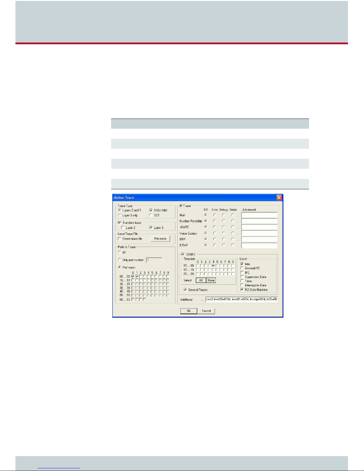
7 System maintenance and software update
7.6 Trace
During operation, the trace readouts of the VoIPBox can be saved in a file or transmitted with
remote maintenance directly. The trace options must be turned on in the GATE Manager (offline or online trace). Trace results presented here are for BRI and VoIP interfaces, and for the
following services in various levels:
Table 7.8 Trace options
Option Definition
Mail Output for all SMTP packets.
NumberPortability Output of all packets for communication with the iMNP.
VoiceCodecs Output of RTCP information described under VP module.
PPP Output of PPP connection information.
DTMF Output for DTMF tone recognition.
Remote Output for GATE Manager and NMS communication.
Figure 7.1 GATE Manager: Online Trace activation window
VoIPBoxes offer two different types of trace:
Online - trace information is immediately displayed in the GATE Manager’s trace
window.
Offline - trace information is written to a file on the VoIPBox.
VoIPBox systems create trace files when the
pabx.cfg. Traces can be activated via remote administration (GATE Manager or FTP).
VoIPBox DSL / VoIPBox BRI – version:20.0.005
TraceLog=file entry is present in the
Page 85
Page 86

7 System maintenance and software update
The following table describes the fields that are on the online trace activation window. For
offline traces, some fields are not available.
Table 7.9 Online trace activation window
Field Description
Trace Type
Layer 2 and 3 Select this option if the trace is to contain layer 2 and 3 messages.
Layer 3 only Select this option if the trace is to contain layer 3 messages only.
DSS1/NI2 Select this option if the trace is to contain DSS1/NI2 messages only.
SS7 For SS7 messages, select this option.
Translate Trace
Layer 2 To translate layer 2 messages into plain text, select this option.
Layer 3 To translate layer 3 messages into plain text, select this option.
Local Trace File
Create Trace File Check this box if you want to store a trace file locally on your computer.
File Name Click this button to change the default directory and file name of the
Ports to Trace
All Select this option to trace all ports.
Only Port Number Enter here the port which you want to trace.
Port Mask Select from this port mask which ports you want to trace.
IP Trace
Mail, Number Portability,
vGATE, ...
CASR2
Timeslots Select which of the channels you want to trace for the CASR2 ports.
General Trace Check this box if you want to run a general trace for the different
Level Select which special type of information you want to trace for the dif-
local trace file.
Contains a list of port-independent trace options. The different options
can be limited to error messages, debug messages, or detailed trace
output. The Advanced field is for TELES support usage only.
For an explanation of the different trace option please refer to
Chapter 7.6 Trace on page 85.
timeslots.
ferent timeslots.
VoIPBox DSL / VoIPBox BRI – version:20.0.005
Page 86
Page 87

7 System maintenance and software update
Table 7.9 Online trace activation window (continued)
Field Description
Additional The following additional entries are possible. The number behind the
colon referes to the trace level. 0 = no traces, 1 = few traces, 2 = many
traces, 3 = very many traces (only nstanl).
autodial:0 for auto dial trace messages
fctrans:trclevel=debug for ISDN facility to SIP converter messages
nstanl:0 for call routing trace messages
radius:0 for RADIUS trace messages
rtman:0 for routing manager trace messages
s0:0 for BRI trace messages
s2m:0 for PRI and switching matrix trace messages
voip:noreg to suppress traces of REGISTER and responses
Please bear in mind that the volume of trace readouts can grow quite large, so that faulty
transmission of the trace data may result with remote maintenance. A trace at full capacity
i
i
can cause the system to crash.
Trace output format
The following entries appear at the beginning and end of each trace:
DD.MM.YY-hh:mm:ss.ss, Start
DD.MM.YY-hh:mm:ss.ss, End
– DD = day
–
hh = hour
–
MM = month
–
mm = minute
–
YY = year
–
ss.ss = hundredths of seconds
Traces appear in the following format:
[<hh:mm:ss>] <module>[<port>]: <trace>
<module>
s = send for PRI/BRI ports
–
–
r = receive for PRI/BRI ports
–
x = send to VoIP destinations
–
y = receive from VoIP destinations
–
i = information messages and internal trace outputs between VoIP and the other
interfaces (ISDN)
a = VoIP controllers RTCP output
–
–
m = mail output
–
g = remote output
<port>
– port number (controller number in the
<trace>
pabx.cfg) or 255 if a service is used
– output in the defined syntax for the module
VoIPBox DSL / VoIPBox BRI – version:20.0.005
Page 87
Page 88

7 System maintenance and software update
7.6.1 ISDN trace output
Trace output for DSS1 is in hexadecimal notation. You can use the external tool Trace-
View.exe
the enclosed CD. The GATE Manager’s trace window can also display translated online traces.
The following example shows an untranslated DSS1 trace:
Example 7.4 ISDN trace output
to translate offline trace output. You will find the tool in the Software folder on
17.05.06-09:54:40,Start 11.7a (L3)
[09:55:14.58] r[00]: 00 01 02 02 08 02 00 02 05 04 03 80 90 a3 18 03 a1 83 81 6c
02 81 31 70 06 81 31 32 33 34 35 7d 02 91 81
[09:55:14.58] s[00]: 02 01 02 04 08 02 80 02 0d 18 03 a9 83 81
[09:55:14.58] s[01]: 00 01 a8 9a 08 02 00 46 05 04 03 80 90 a3 18 03 a1 83 89 6c
02 81 31 70 06 81 31 32 33 34 35 7d 02 91 81
[09:55:14.58] r[01]: 02 01 9a aa 08 02 80 46 0d 18 03 a9 83 89
[09:55:14.86] r[01]: 02 01 9c aa 08 02 80 46 01
[09:55:14.86] s[00]: 02 01 04 04 08 02 80 02 01
[09:55:16.73] r[01]: 02 01 9e aa 08 02 80 46 07 29 05 05 07 01 09 33 4c 07 01 81
31 32 33 34 35
[09:55:16.73] s[01]: 00 01 aa a0 08 02 00 46 0f
[09:55:16.73] s[00]: 02 01 06 04 08 02 80 02 07 29 05 05 07 01 09 32 4c 07 01 81
31 32 33 34 35
[09:55:16.73] r[00]: 00 01 04 08 08 02 00 02 0f
[09:55:44.30] r[00]: 00 01 06 08 08 02 00 02 45 08 02 80 90
[09:55:44.35] s[01]: 00 01 ac a0 08 02 00 46 45 08 02 80 90
[09:55:46.71] r[01]: 02 01 a0 ae 08 02 80 46 4d
[09:55:46.71] s[01]: 00 01 ae a2 08 02 00 46 5a
[09:55:46.71] s[00]: 02 01 08 08 08 02 80 02 4d
[09:55:46.71] r[00]: 00 01 08 0a 08 02 00 02 5a
17.05.06-09:51:33,End
7.6.2 Call forwarding to SIP trace output
To activate the trace output, open the Online Trace activation window and write the following in the Additional field:
fctrans: Shows the internal translation from ISDN facility to SIP message
fcisdn: Translates the ISDN facility messages<argumente>
VoIPBox DSL / VoIPBox BRI – version:20.0.005
Page 88
Page 89
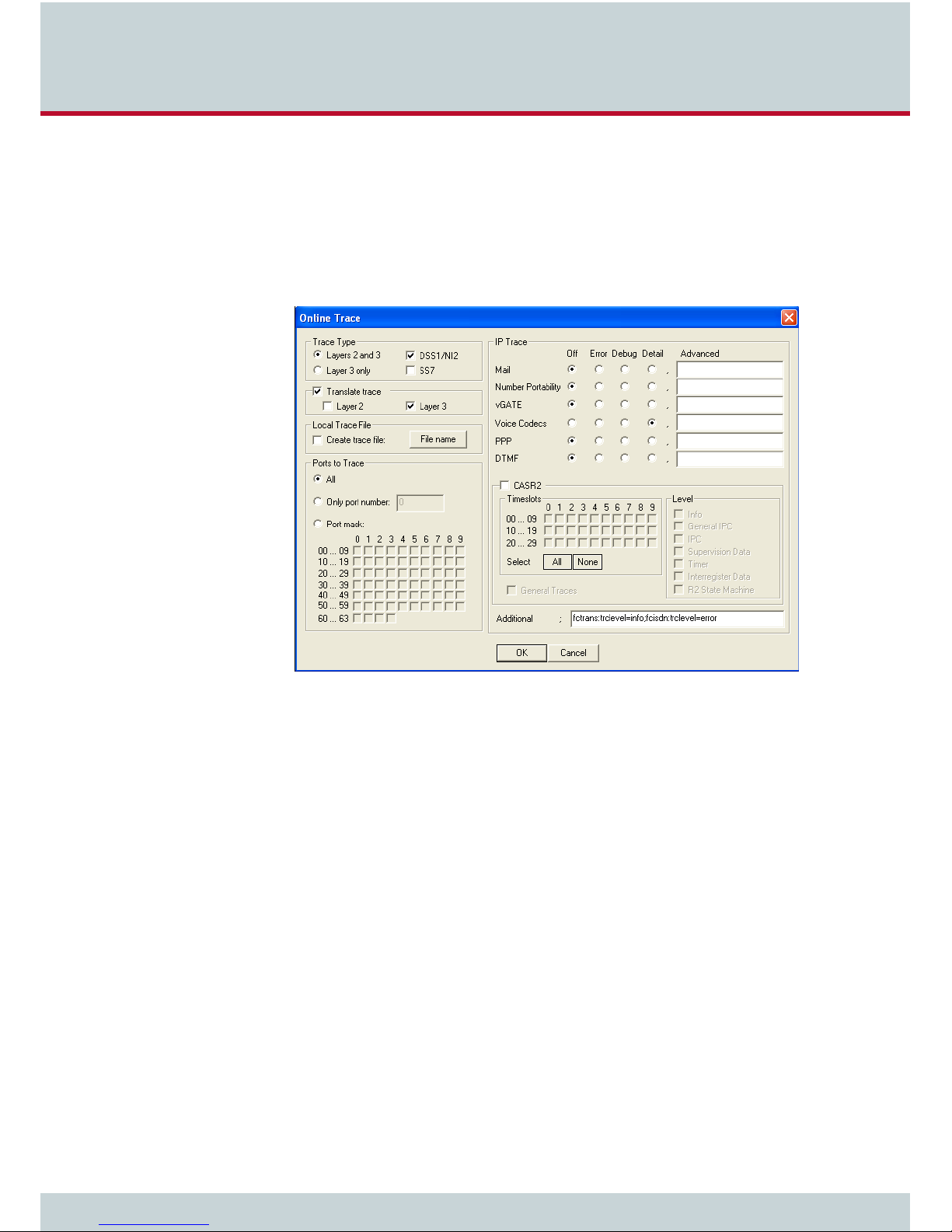
7 System maintenance and software update
The arguments define which traces are to appear and are separated by a comma. The following arguments apply for each module:
trclevel=[info; error; debug]
Info messages allow the user to observe the progress of the translation process.
Detailed information is available at the debug level. Errors (defualt) always appear.
fctype=[all;cf]
This parameter allows the user to select the properties for trace output. The default
setting is all.
Figure 7.2 Online Trace activation window with additional entry
7.6.3 VoIP trace output
As described above in Chapter 7.6, there are four modules for VoIP traces. The groups x
(send), y (receive) and i (information and internal output) appear when a Layer2 or Layer3
offline or online trace is started. Group
Codecs
is active.
Particularly in the case of VoIP connections (protocols H.323 and SIP), the trace output is quite
extensive and abbreviations make it difficult to keep track of the results. The following list
contains a description of H.323 output.
Output for the signaling protocol SIP is transmitted in ASCII and translated for better legibility.
Since they are displayed unabridged, no description is necessary. Information and internal
output traces correspond with the H.323 output and are described in the following tables.
For ENUM, please refer to Chapter 7.6.3.6.
a (RTCP output) only appears when the module Voice
VoIPBox DSL / VoIPBox BRI – version:20.0.005
Page 89
Page 90

7 System maintenance and software update
In general, the following rules apply for this trace output:
Table 7.10 H.323 output
Packet Description
h225
h245
pstn
rcv
snd
The information is thoroughly analyzed where it is received (all rcv messages).
7.6.3.1 Interface IP network
H.225-protocol messages.
H.245-protocol messages.
Messages of the internal protocol interface that provides the interface to the mobile,
PRI and BRI interfaces.
Coming from the IP network or the internal protocol interface; appears with <dir>
in the trace lines.
Sending to the IP network or the internal protocol interface; appears with <dir> in
the trace lines.
Establish H.323 session
Usually there is trace output that displays a new H.323 session. The direction is crucial (whether the call is going into or coming out of the IP network).
The outut syntax is
the IP network and
network
.
Table 7.11 H.323 session
Trace Output Description
connect to
accept from
<ip address>
cr <cr>
s <si>
h225connect to <ip address> cr <cr> s <si> for calls going into
h225accept from <ip address> s <si> for calls coming out of the IP
Outgoing VoIP call
Incoming VoIP call
Peer's IP address
Call reference (corresponds with the internal protocol interface's PSTN call
reference)
Session ID
VoIPBox DSL / VoIPBox BRI – version:20.0.005
Page 90
Page 91

7 System maintenance and software update
H.225 signaling output
The following trace results are for a call coming from the IP network.
and signifies the direction: h225<dir> tpkt msg 0x<mt> h225cr <cr> addr <ip address>.
Table 7.12 H.225 signaling
Trace Output Description
<mt>
<hcr>
<ip address>
Table 7.13 ETS message types
Hex Value Message Type
1 Alerting
2 Call Proceeding
3 Progress
5 Setup
7 Connect
D Setup Acknowledge
5A Release Complete
62 Facility
6E Notify
7B Information
7D Status
rcv will appear at <dir>
The ETS message type in hexadecimal; can consist of values listed in Table
7.13.
H.225 call reference in hexadecimal (does not have to be unique when calls
come from multiple peers).
The peer's IP address.
The following lines show the packet contents in detail.
h225 decode rc 0, q931 msg 0x<mt> = 0, len <length>
h225<type> <mt> voipcfg addr <ip address> rc 0 compr <codec>
h225<type> <mt> h225cr <hcr> FS:<bool> (<codec>,<ip address>,<port>)
TUNN:<bool> H245:<bool>(<ip address>,<port>)
h225<type> <mt> h225cr <hcr> cr <cr>
Table 7.14 Incoming VoIP calls
Trace Output Description
<mt>
len <length>
VoIPBox DSL / VoIPBox BRI – version:20.0.005
Message type in hexadecimal as per ETS standard (see Table 7.13) or written
out as a name.
Packet length in bytes.
Page 91
Page 92

7 System maintenance and software update
Table 7.14 Incoming VoIP calls (continued)
Trace Output Description
h225<type>
addr <ip address>
compr <codec>
FS<bool>
(<codec>,
<ip address>,
<port>)
Tunn<bool>
H245<bool>
(ip address,
port)
h225cr <hcr>
cr <cr>
ALT:<ip address>:<port>,<DA
D>
H.225 rcv or send; received or sent from the IP network.
Peer's IP address.
Peer's compression list (see Table 7.15).
FastStart offered in the signaling packet or not.
Lists codecs offered (seeTable 7.36).
Peer's IP address for RTP data.
Peer's port for RTP Data.
Shows whether or not tunneling is offered as a signaling variant.
Shows an extra H.245 session.
Peer's IP address.
Peer's port.
H.225 message's call reference (does not have to be unique when calls come
from multiple VoIP peers).
Internal call reference (always unique for the call).
Optional alternative values for IP address port or a new destination number
for a facility message with the cause
call forwarded.
Table 7.15 Compression codecs used
Synonym Codec
A
B
C
D
E
F
G
O
P
Q
R
S
T
U
G.711Alaw64k
G.711Ulaw64k
G.7231
G.728
G.729
gsmFullRate
T.38fax
G.729A
G.72616
G.72624
G.72632
G.729B
G.729AB
G.729E
VoIPBox DSL / VoIPBox BRI – version:20.0.005
Page 92
Page 93

7 System maintenance and software update
Table 7.15 Compression codecs used (continued)
Synonym Codec
V
W
X
Y
Z
When the call is sent in the direction of the IP network, the trace will include only the most
important information:
Table 7.16 Calls to the IP network 1
Trace Output Description
<mt>
<num>
<cr>
G.723L
Transparent
G.721
iLBC20
iLBC30
h225<type> <mt1> dad <num> cr <cr>.
Message type written out; if a decimal number appears here, it will be translated as per Table 7.13.
Called party number.
Call reference.
Or: h225<type> callproc typ <mt> cr <cr>.
Table 7.17 Calls to the IP network 2
Trace Output Description
<mt>
<cr>
The ETS message type in hexadecimal.
Call reference.
7.6.3.2 RTP/RTCP output
The RTP/RTCP output displays whether the signaling information corresponds with the contents of the compression chips. The output occurs when a media channel is set up or torn
down:
rtp start cr <cr> ch <ch> li <li> ri <ri> st <st> fx <fx> cp <comp> txm
<factor>
Table 7.18 RTP/RTCP output
Trace Output Description
<cr>
<ch>
<li>
Call reference.
The internal media channel used.
1
appears when the local RTP address (and port) has been defined.
VoIPBox DSL / VoIPBox BRI – version:20.0.005
Page 93
Page 94

7 System maintenance and software update
Table 7.18 RTP/RTCP output (continued)
Trace Output Description
<ri>
<st>
<fx>
<comp>
<factor>
1 appears when the remote RTP address (and port) have been established.
0
appears if the channel's voice packetizer has not yet been started. 1 appears if the voice packetizer can receive, but not send.
voice packetizer can receive and send.
1 appears when T.38 (fax) is used, otherwise 0.
The codec used, as per Table 7.15.
Multiplication factor for default frame size (20ms, 30 ms for G.723).
2 appears when the
The RTP stop message has the following syntax:
Table 7.19 RTP stop message
Trace Output Description
<cr> Call reference.
<ch> The internal media channel used.
VP module
This module's output shows the controller packets for the voice connections. This means that
the RTCP packets and relevant information also appear.
The following results occur for a new RTP connection:
a[<controller>]: <VoIPcodecChipType> start(val) ch=<ch> local=<port> remote=<ip address:port> agg=<bool>
Table 7.20 RTP/RTCP output (VP module)
Trace Output Description
<controller>
<VoIPcodecChipType>
<val>
<ch>
<port>
<ip address>
agg=<bool>
Running number for the VoIP controller.
Stands for the type designation for the compression chips used (e.g. Ac49x).
Shows which connection is set up.
The internal media channel used.
RTP port.
Peer's IP address in hexadecimal.
1
means an RTP-multiplex connection is used (default 0).
rtp stop cr <cr>1 ch <ch>.
The following output shows the channel’s state in the compression chip during a startup or
change of codec.
a[<controller>]: <VoIPcodecChipType>OpenChannelConfiguration ch=<ch> rc=0
a[<controller>]: <VoIPcodecChipType>T38ChannelConfiguration ch=<ch> rc=0
VoIPBox DSL / VoIPBox BRI – version:20.0.005
Page 94
Page 95

7 System maintenance and software update
a[<controller>]:<VoIPcodecChipType>ActivateRegularRtpChannelConfiguration ch=<ch> rc=0
The following output shows whether the compression chip starts sending and receiving packets:
a[<controller>]: <VoIPcodecChipType> ch <ch> establish
Sent and received bytes appear with the following output results:
a[<controller>]: <VoIPcodecChipType> ch <ch>: in <byte> out <byte>
Table 7.21 RTP packet statistics
Trace Output Description
<ch>
<byte>
The following output shows the RTCP packet statistics:
a[<controller>]: <VoIPcodecChipType> ch <ch> rtcp<dir> <num> ji <ji> rt
<rt> fl <fl> in <byte> out <byte>
Table 7.22 RTCP packet statistics
The internal media channel used.
The call's received or sent bytes.
.
Trace Output Description
<ch>
rtcp<dir>
<num>
<ji>
<rt>
<fl>
<cl>
The following output shows the jitter buffer status:
a[<controller>]: <VoIPcodecChipType> ch <ch> jitter buffer n1 n2 n3n4 n5
n6 n7 n8
Table 7.23 Jitter buffer status
Trace Output Description
n1
n2
n3
The internal media channel used.
R sender report (received) is more interesting, since it comes from the peer.
T sender report (transmitted).
0
1 SenderReport packet
2 Packet requested by the driver
Delay jitter [msec].
Round-trip local<->remote, round-trip delay [msec].
Fraction lost: Fraction of packets lost [8lsb].
Cumulative lost: number of lost packets [24lsb].
SteadyStateDelay in milliseconds
NumberOfVoiceUnderrun
NumberOfVoiceOverrun
ReceiverReport packet
VoIPBox DSL / VoIPBox BRI – version:20.0.005
Page 95
Page 96

7 System maintenance and software update
Table 7.23 Jitter buffer status (continued)
Trace Output Description
n4
n5
n6
n7
n8
An RTP connection has ended when the following trace output appears:
a[<controller>]: <VoIPcodecChipType> stop ch=<ch>
Table 7.24 RTP stop message (VP module)
Trace Output Description
<ch>
NumberOfVoiceDecoderBfi (bfi = bad frame interpolation)
NumberOfVoicePacketsDropped
NumberOfVoiceNetPacketsLost
NumberOfIbsOverrun (ibs = in band signaling)
NumberOfCasOverrun
The internal media channel used.
The following output results when the codec changes for a fax connection:
a[<controller>]: ac49x ch <ch> fax/data n1 n2 n3
Table 7.25 Codec change for fax
Trace Output Description
n1
n2
n3
Table 7.26 fax or data signal event
Value Definition Description
0 SILENCE_OR_UNKNOWN Undefined (unknown signal or silence)
1 FAX_CNG CNG-FAX (calling fax tone, 1100 Hz)
2 ANS_TONE_2100_FAX_CED_OR_
MODEM
3 ANS_TONE_WITH_REVERSALS ANS (answer tone with reversals)
4 ANS_TONE_AM ANSam (AM answer tone)
5 ANS_TONE_AM_REVERSALS ANSam (AM answer tone with reversals)
6 FAX_V21_PREAMBLE_FLAGS FAX-V.21 preamble flags
Fax bypass flag:
0 Voice, data bypass or fax relay
1 Fax bypass
Signal detected on decoder output (see Table 7.26)
Signal detected on encoder input (see Table 7.26)
FAX-CED or modem-ANS (answer tone, 2100 Hz)
VoIPBox DSL / VoIPBox BRI – version:20.0.005
Page 96
Page 97

7 System maintenance and software update
Table 7.26 fax or data signal event (continued)
Value Definition Description
7 FAX_V8_JM_V34 FAX-V.8 JM (fax call function, V.34 fax)
8 VXX_V8_JM_VXX_DATA V.XX-V.8 JM (data call function, V-series modem)
9 V32_AA V.32 AA (calling modem tone, 1800 Hz)
10 V22_USB1 V.22 USB1 (V.22(bis) unscrambled binary ones)
11 V8_BIS_INITIATING_DUAL_TONE V.8bis initiating dual tone (1375 Hz and 2002 Hz)
12 V8_BIS_RESPONDING_DUAL_TONE V.8bis responding dual tone (1529 Hz and 2225 Hz)
13 VXX_DATA_SESSION V.XX data session
14 V21_CHANNEL_2 V.21 channel 2 (mark tone, 1650 Hz)
15 V23_FORWARD_CHANNEL V.23 forward channel (mark tone, 1300 Hz)
16 STU_MODEM STU Modem
17 V25_CALLING_TONE V.25 Calling Tone (CT)
18 V21_CHANNEL_1=18 V.21 channel 1 (mark tone, 980 Hz)
19 BELL_103_ANSWER_TONE Bell 103 answer tone, 2225 Hz
20 TTY TTY
21 FAX_DCN FAX-DCN (G.3 fax disconnect signal)
The following output appears when the compression chip recognizes DTMF tones:
a[<controller]: ac49x ch <ch> ibs <dtmf> <dir> <mode> <lev> <dur>.
Table 7.27 DTMF tone recognition
Trace Output Description
<ch>
<dtmf>
<dir>
<mode>
<lev>
<dur>
Media channel
Recognized DTMF tone in the stream or as per RFC2833
Direction
0 Coming from BRI/analog
1 Coming from VoIP
0 Tone has ended
1 Tone has been recognized
Signal level in -dBm
Tone duration
7.6.3.3 Internal protocol interface (to ISDN, POTS, mobile)
These trace outputs always begin with the keyword
message type. The message is then either concluded or other information follows:
pstn, followed by the direction and the
VoIPBox DSL / VoIPBox BRI – version:20.0.005
Page 97
Page 98

7 System maintenance and software update
pstn<type> <mt1> dad <num> oad <num> cc <value> cc <cc> id <id> c/c <ctrl>/
<ch> cr <cr>
Table 7.28 Internal protocol interface
Trace Output Description
<type>
<mt1>
<num>
<cc>
<id>
<ctrl>
<ch>
<cr>
Direction from (rcv) or to (snd) the internal protocol interface.
Message type written out; if a decimal number appears, it will be translated
as per Table 7.13.
DAD<num>
Value for OAD field element:
20 OAD network type provided
40 OAD with sending complete
80 OAD presentation restricted
Internal ident for the call leg.
Controller used (counting starts with 0).
Media channel used (counting starts with 1).
Internal call reference /, followed by 0 or call reference of the VoIP leg.
= called party number, OAD<num> = calling party number.
Output also appears when a call comes from the internal protocol interface and is assigned
to a VoIP profile. The characters appear in front of the colon in the routing entry.
pstnrcv get_voipcfg <voip profile> compr <list>
Table 7.29 Received from PSTN 1
Trace Output Description
<voip profile>
<list>
Assignment of media channel used for the internal interface and the ISDN call reference for
the VoIP call's appears as follows:
pstnrcv bchanind cr <cr> ch <chan> isdncr <icr>
Table 7.30 Received from PSTN 2
Trace Output Description
<cr>
<chan>
<icr>
Defines the VoIP profile to be used.
Defines the compression algorithms offered.
Call reference.
Media channel used for the internal protocol interface (DSS1).
Call reference for the internal protocol interface (DSS1).
VoIPBox DSL / VoIPBox BRI – version:20.0.005
Page 98
Page 99

7 System maintenance and software update
7.6.3.4 H.245 messages
The following trace output is possible:
h245<dir>(<tt>) cr <cr>
Table 7.31 H.245 messages
Trace Output Description
<dir>
<tt>
<cr>
Following this trace output, either a detailed description of the message and its corresponding
message type, including negotiating information, or trace output elements that are explained
later appear. The most important message types that contain further information elements
are as follows.
... TerminalCapabilitySet peer=<comp> cfg=<comp>
... TerminalCapabilitySet <comp>
The message's direction; rcv (incoming from the peer) or snd (sent message).
H.245 transport type.
Internal call reference.
Table 7.32 Codec used
Trace Output Description
<comp>
List of compression codecs offered (see Table 7.15), the list of the peer's codecs appears behind peer, and
VoIP profile
The output syntax for the logical channel parameters is as follows:
... OpenLogicalChannel cn=<cn> cpr=<comp> sessid=<sid> ctrl=<ip address>:<rtcp port>
... OpenLogicalChannelAck cn=<cn> sessid=<sid> media=<ip address>:<rtp
port>
Table 7.33 Logical channel parameters
Trace Output Description
<cn>
<sid>
<comp>
<ip address>
<rtcp port>
<rtp port>
H.245 channel number per H.225 connection.
Session ID.
Codec used (see Table 7.15).
Protocol peer IP address.
Port used for the protocol RTCP.
Port used for the protocol RTP.
cfg shows which codecs are defined in the
The trace output is as follows when the message type is not translated or is ignored:
VoIPBox DSL / VoIPBox BRI – version:20.0.005
Page 99
Page 100

7 System maintenance and software update
h245<dir>(<tt>) cr <cr> unknown msg <hmt> <hmi>
Table 7.34 H.245 parameters
Trace Output Description
hmt
hmi
Table 7.35 Multimedia system control message types
ID Message
0 (Table 7.36) Request
1 (Table 7.37) Response
2 (Table 7.38) Command
3 (Table 7.39) Indication
The H.245 message type (multimedia system control message type), (Table 7.35).
The H.245 message ID (see Table 7.36, Table 7.37, Table 7.38, Table 7.39).
Depending on the system control message type, one of the following message IDs appear.
Table 7.36 Message IDs for request message
ID Message
0
NonStandard
1
MasterSlaveDetermination
2
TerminalCapabilitySet
3
OpenLogicalChannel
4
CloseLogicalChannel
5
RequestChannelClose
6
MultiplexEntrySend
7
RequestMultiplexEntry
8
RequestMode
9
RoundTripDelayRequest
10
MaintenanceLoopRequest
11
CommunicationModeRequest
12
ConferenceRequest
13
MultilinkRequest
14
LogicalChannelRateRequest
VoIPBox DSL / VoIPBox BRI – version:20.0.005
Page 100
 Loading...