

Page 1
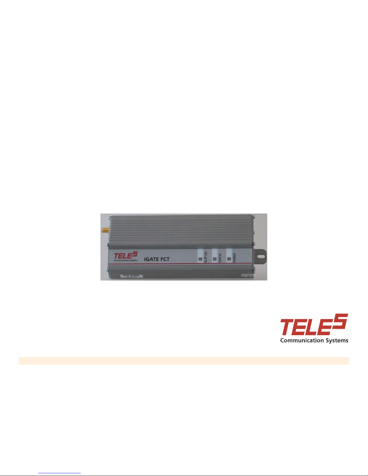
Table of Contents Next Page
TELES iGATE FCT
User’s Manual
Page 2

TELES iGATE FCT User’s Guide 2
Previous Page Table of Contents Next Page
Contact Information
TELES AG Headquarters
Ernst-Reuter-Platz 8
Berlin, Germany
10587
+49 30 399 28-00
+49 30 399 28-01
Email: [email protected]
Web: www.teles.com/tcs
Trademarks and Document Information
TELES AG Informationstechnologien. All rights reserved.
TELES
®
, IntraSTAR®, iGATE®, and iSWITCH® are registered trademarks of TELES AG Informationstechnologien.
All other trademarks used are the property of their respective owners.
Document number MM2078–04, March 2008
© TELES Ltd.
Certification, Version Information, and Disclaimer
iGATE FCT carries CE Certification.
This manual is applicable to TELES iGATE FCT with soft-
ware versions 0218 or higher. These apply to units with
part number Q11-111093 (900/1800MHz) and Q11111083 (850/1900MHz) with version numbers: B or
higher. The part number and version number are marked
on a sticker located at the bottom or the side of the unit
(see section 1.3 – product identification). Other versions
may differ slightly in some aspects.
TELES Ltd. and its distributors assume no responsibility
for any damage or loss resulting from the use of its products or this user manual. TELES Ltd. and its distributors
assume no responsibility for any loss or claims by third
parties, which may arise through the use of its products.
Page 3

TELES iGATE FCT User’s Guide i
Previous Page Next Page
Table of Contents
INTRODUCTION ............................................................1
Overview......................................................................... 2
Product Components & ID.............................................. 2
Contents of Package...................................................... 3
Safety Precautions ......................................................... 3
GETTING STARTED ......................................................4
Installing the Unit............................................................ 5
Initial Start-up and LEDs................................................. 7
Testing the Installation.................................................... 8
Checking Outgoing Calls.......................................... 8
Checking Incoming Calls.......................................... 8
Instructions for Users...................................................... 9
PROGRAMMING .........................................................10
How to Program............................................................ 11
Programming Summary.......................................... 12
Features ....................................................................... 13
Audio Gain.............................................................. 13
Call Duration Limit .................................................. 13
Calling Line Identification Restriction (CLIR) ......... 14
Clearing a Lock...................................................... 14
Erase SMS Inbox of the SIM card.......................... 14
Immediate Dialing.................................................. 15
Interdigit Timeout................................................... 15
Network Lock......................................................... 16
PIN Code Programming......................................... 16
Restore Factory Default......................................... 18
Set Pulse Drop Signaling Method.......................... 18
Set Pulse Drop Width............................................. 19
Set Reverse Polarity Signaling Method ................. 19
Toll Restriction....................................................... 19
Factory Default Values ................................................ 21
SMS .............................................................................22
SMS Commands Overview.......................................... 23
GET Command Table.................................................. 23
SET Command Table.................................................. 24
MISCELLANEOUS ...................................................... 25
Call Progress Tones.................................................... 26
LED Indications............................................................ 26
Troubleshooting........................................................... 27
Specifications............................................................... 28
Page 4

TELES iGATE FCT User’s Guide 1
Previous Page Table of Contents Next Page
Chapter 1
Introduction
This section includes:
• “Overview” on page 2
• “Product Components & ID” on page 2
• “Contents of Package” on page 3
• “Safety Precautions” on page 3
Page 5
TELES iGATE FCT User’s Guide 2
Previous Page Table of Contents Next Page
Overview
The iGATE FCT gateway enables direct connection of an
organization's internal telephony system to a commercial
cellular network via an existing Private Automatic Branch
Exchange (PABX) system.
The iGATE FCT interfaces with a regular two-wire analogue line interface and a GSM cellular network to create
a cellular gateway. iGATE FCT operates via dual band
GSM cellular networks (900/1800MHz). A special version
operates at 900/1900MHz.
When the PABX supports Least Cost Routing (LCR), use
of the iGATE FCT is transparent. The PABX recognizes
iGA TE FCT as a trunk interface and the routin g is done in
the P ABX itself. In a PABX that does not support LCR, the
user must select the proper trunk for the call.
The iGATE FCT can be used with a plain analog telephone. In this case, when the hand-set is lifted, the
iGATE FCT sends a dial tone. This configuration can
replace a fixed line telephone.
The iGATE FCT can be used to send and receive SMS,
fax and data transmissions. These features are optional.
Contact Technical Support for further information.
Product Components & ID
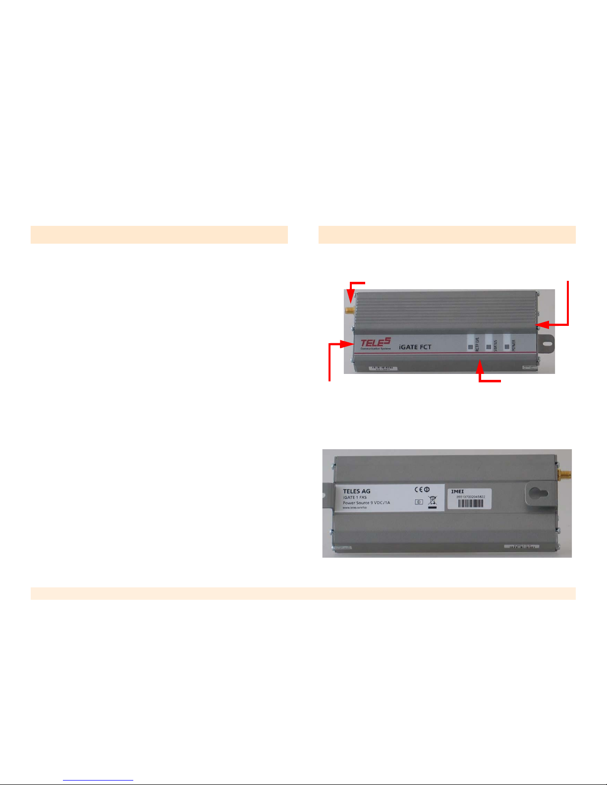
Figure # 1 illustrates the main components of the iGATE
FCT.
Figure 1: iGATE FCT Components
Product information is listed on the sticker on the bottom
of the iGATE FCT.
Antenna Connector
SIM Drawer
LED Panel
Connection Pane
Page 6

TELES iGATE FCT User’s Guide 3
Previous Page Table of Contents Next Page
Contents of Package
The iGATE FCT is shipped with the following components:
• iGATE FCT unit
• One antenna with a 3-meter cable
• Power cable (AC adaptor with rated output 9VDC, 1A)
• Three screws
• This user manual
The following items may be supplied on a separate order:
• Data cable for Fax and SMS
• An antenna with a 15-meter cable
Safety Precautions
To avoid injury and prevent equipment damage, observe
the following safety precautions:
• Do not ship equipment unless it is properly packed in
its original wrapping and shipping containers.
• Connect the power cable first and then the analog
lines.
• When disconnecting the equipment, disconnect the
analog lines first, then the power cable, and only then
the ground connection of the rear panel.
• Do not connect the iGATE FCT to any power source
other than the nominal source indicated on the front
power panel.
• Make sure that the equipment top, bottom, and sides
are not blocked to air movement.
Page 7

TELES iGATE FCT User’s Guide 4
Previous Page Table of Contents Next Page
Chapter 2
Getting Started
This section includes:
• “Installing the Unit” on page 5
• “Initial Start-up and LEDs” on page 7
• “Testing the Installation” on page 8
• “Instructions for Users” on page 9
Page 8
TELES iGATE FCT User’s Guide 5
Previous Page Table of Contents Next Page
Installing the Unit
To install the iGATE FCT:
1. Select a location for the iGATE FCT. The location
must meet the following criteria:
• indoors
• near a power socket
• near a proper location for the antenna
2. Drill holes in the wall matching the wall mounting
brackets of the iGATE FCT.
3. Screw the unit onto the wall.
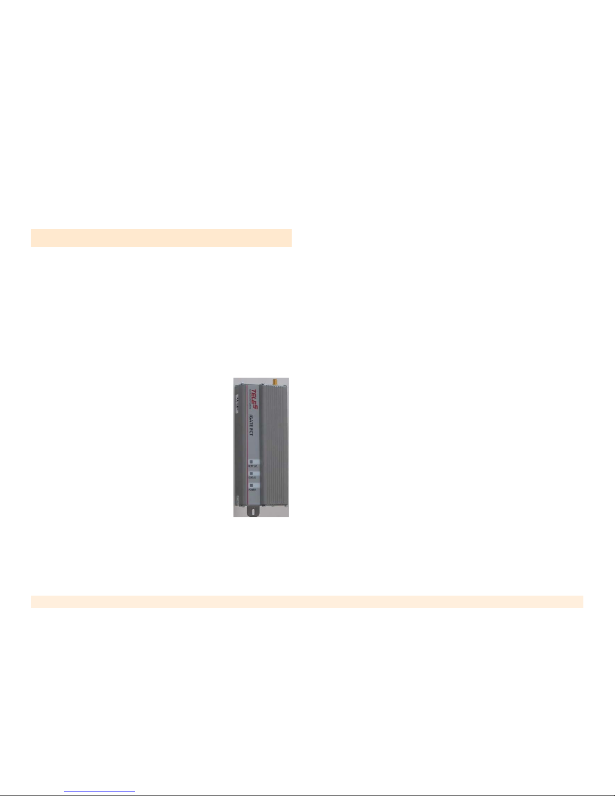
The unit must be placed in the orienta-
tion shown to the right, with the
antenna socket up and the connection
panel down.
4. Connect the antenna to the antenna
connector located on top of the unit.
5. Ensure that a separate metal plate is
available for each unit being installed.
Each antenna should be placed on a
metal plate. If metals plate are not
available, complete the installation and add the metal
plates later. The antenna base is magnetic, so an iron
plate is preferred.
6. Select a location for the antenna. The location must
meet the following criteria:
• at least one meter away from the unit
• with room for the metal plate
• with room for the antenna to stand in an upright
position
• if installing more than one unit, each antenna
should be on a separate plate with a minimum of
30 cm between each antenna.
7. Select a SIM card. The SIM card should meet the following criteria:
• It is easier to use a SIM card without a PIN code.
• If using a SIM card with a PIN code, we
recommend first resetting the PIN code to #1234.
(To program a SIM card, place it in a mobile phone
and follow the phone’s menu.) Then, either use
the default PIN code or change the PIN code using
the unit’s DTMF programming process.
• The SIM card should not support call waiting or
voice mail. If these features are needed, use a
mobile phone to define the message center for
SMS transmissions.
8. Open the SIM drawer by inserting a dull, thin object
into the button.
9. Place the SIM card in the tray. Ensure that the SIM
card’s contacts face the back of the tray.
Page 9
TELES iGATE FCT User’s Guide 6
Previous Page Table of Contents Next Page
10. Close the SIM card tray.
11. Connect the routed trunk port of the PABX (FXO) to
the LINE port (FXS) of the iGATE FCT.
Note: Ensure that the PABX’s routed trunk port is a trunk interface
that was pre-programmed to deliver cellular calls.
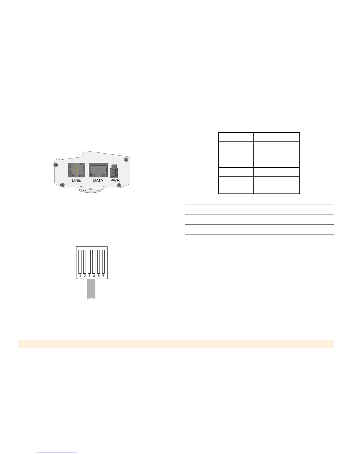
Figure # 1 illustrates the pin layout of the RJ-11 connector. Table 1 details its pin-to-wire layout.
Figure 2: RJ-11 Line Connector Pin Layout
Warning: Do not use the reserved pins.
Note: The line can use either pins 3 and 4 or pins 2 and 5.
12. Ensure that the PABX is properly configured. For
details regarding the programming of the PABX, refer
to the PABX’s documentation or contact its Technical
Support staff.
Proper configuration includes:
a. Set the trunk dialing method to standard DTMF
(dual tone multi frequency). Pulse dialing is not
supported.
b. Create a new trunk group for all trunks connected
to iGATE FCT devices and serving the same
Table 1: RJ-11 Connector Pin Layout
PIN # FUNCTION
1Reserved
2Tip
3Tip
4Ring
5Ring
6Reserved
Page 10

TELES iGATE FCT User’s Guide 7
Previous Page Table of Contents Next Page
cellular network. You may create several groups,
serving several networks.
c. Determine if the PABX does or does not support
Least Cost Routing (LCR).
• On PABX's supporting LCR, set the PABX
routing tables to route the calls to the trunk
groups. This is done by selecting the cellular
prefixes to direct the routing. Calls that should
not be made on the iGATE FCT can be
blocked by using the Toll Restriction feature
(see p. 19). The PABX will automatically route
calls to the iGATE FCT.
• On PABX's that do not support LCR, ensure
users know how to select the right trunk for the
cellular calls (see “Instructions for Users” on
page 9). After making the selection, users will
hear a second dial tone, this one emitted by
the iGATE FCT.
13. Connect the power cable.
14. Continue with the next section, entitled “Initial S tart-up
and LEDs”.
Initial Start-up and LEDs
After the power cable is attached, the POWER LED
should be illuminated. If it is not, ensure that the cable is
properly connected to the unit and to the AC mains.
During the first seconds, the STATUS LED blinks. This
indicates that the unit is initializing. Once the SIM card is
registered and operational, the STATUS LED stops
blinking. In certain cases, the LED may continue to blink.
This is normal and reasons appear later in this document.
Verify that the RCPT LVL LED is green. This indicates a
high reception level. (Reception levels are described in
Table 2.) To improve the reception level, move the
antennas to a different location with a better reception
and/or place the antennas on a metal plate no smaller
than 30 x 30cm. If the reception level is still not satisfactory, contact Technical Support.
Table 2: Reception Level Indications
RCPT LED Reception Level
Green High reception -75dBm to - 51dBm
Orange Medium reception -87dBm to -77dBm
Red Low reception -101dBm to -89dBm
Off
Very low reception or
no reception at all
-113dBm to -103dBm
Page 11

TELES iGATE FCT User’s Guide 8
Previous Page Table of Contents Next Page
Testing the Installation
After installation and power up, perform the following
tests. These tests verify that the unit is operational.
Checking Outgoing Calls
1. Disconnect the PABX cable from the LINE connector
and, in its place, connect an analog telephone.
2. Pick up the hand-set. A normal dial tone should be
audible. If there is no dial tone, see “Troubleshooting”
on page 26.
3. Dial out to a known cellular telephone number. The
ring-back tone should be heard.
• If there is no ring-back tone, make sure that the
number dialed is a valid number.
• If there is a ring-back tone but no connection, try
dialing another number.
4. When the called party answers, ensure that there is a
clear bi-directional voice path and the STATUS LED is
red.
Note: Ensure that the dialed number does not conflict with the toll
restriction rules, if activated.
Checking Incoming Calls
1. Using a second phone, dial the phone number of the
SIM card inserted in the iGATE FCT.
2. Upon hearing the ring, pick up the hand-set of the
analog telephone (connected at the beginning of the
first test).
3. Ensure that there is a clear bi-directional voice path
and the STATUS LED is red.
If there is no response from the channel, ensure that
the dialed number is the correct number for the SIM
card.
Note: To verify a SIM card number: remove the SIM card from the
iGATE FCT and insert it in a cellular phone. Dial out to another
phone with a display or use the incoming number identification
(CLIP) feature of the cellular phone.
If the number is correct and incoming calls are still not
received, contact Technical Support.
Once the channel is working properly, restore the connections to the PABX. If the unit does not function properly,
contact Technical Support.
Page 12

TELES iGATE FCT User’s Guide 9
Previous Page Table of Contents Next Page
Instructions for Users
We recommend distributing the following instructions to all
iGATE FCT users.
• Do not wait more than 3 seconds between the digits of
the dialed number.
• For PABX's without LCR, the system administrator
must explain how to select the proper gateway , that is,
what prefix to dial.
• If Toll Restriction is active in a PABX without LCR,
some destinations will not be reachable because the
call will be too expensive. Use the proper prefix.
• If Call Duration Limit is active, calls longer than the
time limit will be cut.
• The iGATE FCT collects the dialed digits and places
the call when one of the following occur:
• the # key is pressed
• the Inter-digit timeout period expires. See
“Interdigit Timeout” on page 15. The default
timeout is 3 seconds.
• if Immediate Dialing is enabled, when the defined
number of digits are dialed. See “Immediate
Dialing” on page 15.
Page 13

TELES iGATE FCT User’s Guide 10
Previous Page Table of Contents Next Page
Chapter 3
Programming
This section includes:
• “How to Program” on page 11
• “Programming Summary” on page 12
• “Features” on page 13
• “Factory Default Values” on page 20
Page 14
TELES iGATE FCT User’s Guide 11
Previous Page Table of Contents Next Page
How to Program
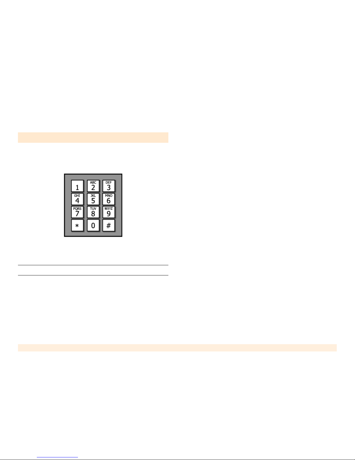
All programming is done using the keypad of a Dual Tone
Multi-Frequency (DTMF) telephone, similar to the keypad
pictured in this illustration.
To program the iGATE FCT:
1. Connect a DTMF telephone to the LINE connector.
Note: Alternately, dial through the PABX to the iGATE FCT unit.
2. Dial the sequence **1343**#. The iGATE FCT will
respond with 3 short beeps to confirm it. If the code
was wrong you will hear the error tone, meaning that
the command was not accepted (probably because
you entered it wrong). During programming:
• 3 short beeps indicate positive confirmation
(confirmation tone).
• 2 short beeps indicate rejection or inability to
perform the command (rejection tone).
3. Enter parameters using the DTMF tones. We recommended that you check the function of every feature
you program and write it down, as there is no simple
way to know what was programmed into the channel.
If in doubt - reprogram the channel.
Note the following rules:
• The commands are in effect immediately after you
dial their codes.
• Each parameter is saved in the unit’s permanent
memory . The p arameters wi ll not be "forgotten" in
case of power failure.
• Each feature has a default value that is set during
production (Factory default).
• If you made a lot of changes and want to start from
fresh, or you want to delete all the programming
changes made to the channel - use the "Restore
Factory Default" feature.
4. Hang-up to leave the programming mode.
Page 15
TELES iGATE FCT User’s Guide 12
Previous Page Table of Contents Next Page
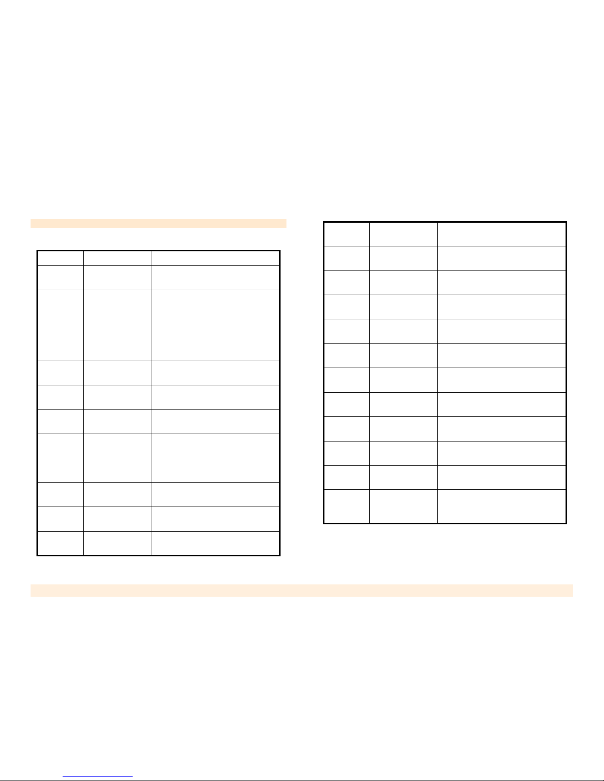
Programming Summary
Table 3: DTMF Programming Summary
Code Function Remarks
**1343**#
Enter programming mode
To exit programming mode, hangup.
*3210*#
Update Immediate Dialling. The
channel will start
dialling immediately after
receiving this
number of digits
This is followed by the number of
digits required for Immediate Dialling and then by #. Enter “0” to
disable Immediate Dialing.
*3211*#
Update Interdigit Timeout
See “Interdigit Timeout” on
page 15.
*5351*#
Erase Toll
Restriction table
See “Toll Restriction” on page 19.
*5470*#
Restore Factory
Default
See “Restore Factory Default” on
page 18.
*5580*#
Change Rx/Tx
audio gain
See “Audio Gain” on page 13.
*6100*#
Enable SIM PIN
code feature
See “PIN Code Programming” on
page 16.
*6101*#
Disable SIM PIN
code
See “PIN Code Programming” on
page 16.
*6110*#
Change SIM PIN
code
See “PIN Code Programming” on
page 16.
*6122*#
Clear Channel
Lock
See “Clearing a Lock” on page 14.
*6133*#
Call Duration
Limit
See “Call Duration Limit” on
page 13.
*6150*#
Erase SMS mailbox
See “Erase SMS Inbox of the SIM
card” on page 14.
*8200*# Enable CLIR
See “Calling Line Identification
Restriction (CLIR)” on page 14.
*8201*# Disable CLIR
See “Calling Line Identification
Restriction (CLIR)” on page 14.
*8600*#
Enable Comfort
Tone
This activates a short beep that is
played in place of silence.
*8601*#
Disable Comfort
Tone
This deactivates the comfort tone.
*8620*#
Enable Module’s Dial Tone
Creates a dial tone matching that
heard in the United States
*8621*#
Disable Module’s Dial Tone
Disables the US dial tone
*9190*#
Enable Toll
Restriction
See “Toll Restriction” on page 19.
*9193*#
Disable Toll
Restriction
See “Toll Restriction” on page 19.
*9194*#
Add entry to Toll
Restriction table
See “Toll Restriction” on page 19.
*9195*#
Remove entry
from Toll Restriction table
See “Toll Restriction” on page 19.
Table 3: DTMF Programming Summary
Page 16

TELES iGATE FCT User’s Guide 13
Previous Page Table of Contents Next Page
Features
This section lists the various iGATE FCT features, which
can be programmed by the user. Section 4.10, has a concise summary of the programming details.
Audio Gain
Use this parameter to adjust the volume. The level can be
changed in both directions.
1. Dial ** 1343**#. The unit enters the programming
mode and emits the confirmation tone.
2. Dial *5580*#. The unit enters the 'change Rx/Tx gain'
mode and emits the confirmation tone.
3. Dial to a cellular phone and add the # sign to the end
of the phone number. (The phone number must have
at least 3 digits.) The unit emits the confirmation tone.
Wait until the call is answered.
4. Dial either:
• *70*# for Tx gain
• *71*# for Rx gain
The unit emits the confirmation tone.
5. Adjust the volume by pressing the keys on the key pad
followed by the # sign.
Note: In some units, the 2 and 8 keys are interchanged.
6. Dial 5# to save the changes.
Call Duration Limit
The duration of incoming and outgoing calls can be limited. If the call duration exceeds the limit, the call is
stopped and the user hears an error tone. To continue the
call, the user has to redial.
By default, this feature is disabled and call length is unlimited.
Table 4: Audio Gain Commands
Key Result
2# Increase gain *
8# Decrease gain *
6# Apply the default settings
4# Reapply the previous settings
* Upon reaching the end of the gain scale, the
unit emits the 2-beep rejection tone.
Page 17

TELES iGATE FCT User’s Guide 14
Previous Page Table of Contents Next Page
To enable Call Duration Limit:
1. Dial ** 1343**#. The unit enters the programming
mode and emits the confirmation tone.
2. Dial *6133*#. The unit emits the confirmation tone.
3. Dial the maximum allowed time—between 1 and 254
minutes. A number between 254 and 999 will be
accepted as 254. A number over 999 will be rejected.
To disable this feature, dial *6133*#0#.
Calling Line Identification Restriction (CLIR)
This parameter determines whether or not the iGA TE FCT
sends its SIM number to the called party.
1. Dial ** 1343**#. The unit enters the programming
mode and emits the confirmation tone.
2. Dial either:
• *8200*#. This allows the presentation of the SIM
number to the called party.
• *8201*#. This hides the SIM number from the
called party.
The unit emits the confirmation tone.
Clearing a Lock
Lock occurs after an unsuccessful attempt to change the
PIN code. The unit will not perform any command relevant to a PIN code change until the Lock is cleared.
To clear the lock:
1. Dial ** 1343**#. The unit enters the programming
mode and emits the confirmation tone.
2. Dial *6122*#. The unit emits the confirmation tone
and clears the lock.
Alternately, clear the lock by inserting a SIM card that
does not request a PIN code. The unit notes that the SIM
card does not require a PIN code and, consequently,
clears the lock.
WARNING! SIM cards lock after 3 failed tries. If using the
alternate method to clear the lock, do not reinsert the first SIM card.
Once the SIM card locks, it can only be unlocked with the PUK
number.
Erase SMS Inbox of the SIM card
Use this command to erase all messages stored in the
SMS inbox of the SIM.
This feature is important when using SMS commands to
remotely control the unit. The inbox of the SIM usually
Page 18

TELES iGATE FCT User’s Guide 15
Previous Page Table of Contents Next Page
stores no more than 20 messages. When the inbox is full,
the unit cannot receive SMS messages and, as a consequence, remote control of the unit is disabled.
1. Dial ** 1343**#. The unit enters the programming
mode and emits the confirmation tone.
2. Dial *6150*#. The unit erases all stored messages
and emits the confirmation tone.
Note: The confirmation tone can be delayed up to 30 seconds,
depending on current inbox volume.
Immediate Dialing
Use this parameter to define how many digits have to be
dialed before the iGATE FCT automatically places the
call. This feature is especially useful if the unit is installed
in a network where all the cellular phones have the same
number of digits. Setting the Immediate Dialing length to
that number of digits avoids the delay after the last digit.
Note: When the number of digits is set to the network standard—
for example, 9—shorter numbers are sent to the cellular network
after the preset delay or after pressing the # sign.
1. Dial ** 1343**#. The unit enters the programming
mode and emits the confirmation tone.
2. Dial *3210*#. The unit emits the confirmation tone.
3. Dial the number length—between 2 and 20 digits—
followed by the # sign. For example, if you dial 10#,
the iGATE FCT will place the call after 10 digits have
been dialed.
Note: To disable this feature, enter 0#.
Interdigit Timeout
The iGATE FCT collects the dialed digits and places the
call when the Inter-digit timeout period expires. The
default timeout is 3 seconds. Use this parameter to
change the default.
Note: If the “Immediate Dialing” feature is not activated, the actual
call initiation will also be delayed. To overcome this, activate the
“Immediate Dialing” feature or press the # key after the final digit.
1. Dial ** 1343**#. The unit enters the programming
mode and emits the confirmation tone.
2. Dial *3211*#. The unit emits the confirmation tone.
3. Dial the timeout length—up to 9 seconds—followed by
the # sign. For example, if you dial 5# the timeout
between dialed digits is set to 5 seconds.
Page 19

TELES iGATE FCT User’s Guide 16
Previous Page Table of Contents Next Page
Network Lock
Network Lock prevents the use of an unauthorized SIM
card in the iGA TE FCT. Once Network Lock is enabl ed, if
an unauthorized SIM card is used, the iGA TE FCT will not
process either incoming or outgoing calls. Instead, it will
generate an error tone on outgoing calls and will reject
incoming calls.
Network Lock feature may be either disabled or enabled
when you receive the unit. To change the setting, call
Technical Support.
PIN Code Programming
Certain countries require that every SIM card be assigned
a PIN code. The purpose of this requirement is to protect
the SIM card against unauthorized use.
Overview
To use a PIN-code protected SIM-card, activate it and
insert it into the iGATE FCT. Every time the unit powers
up, it delivers the stored PIN code to the SIM card. If the
code matches, the unit functions normally. If the code is
wrong, the unit locks itself, ceases functioning, and the
STATUS LED blinks. See “Clearing a Lock” on page 14.
Note: The unit locks in order to prevent the SIM card from locking.
SIM cards lock after 3 failed tries. Once the SIM card locks, it can
only be unlocked with the PUK number.
The PIN code protection can be used in several ways:
• PIN Code protection can be disabled. Then, use any
SIM card programmed to function without a PIN code.
• Use the default PIN code of 1234. The unit is preprogrammed with this code. Use a SIM card programmed to require the default code 1234.
• Use a custom PIN code. Use a SIM card with a
known PIN code and to program the code into the unit.
Enabling Protection When the PIN Code is Known
If the SIM card’s existing PIN code is known, there are
two possibilities:
1. Insert the SIM card into the unit.
2. Dial ** 1343**#. The unit enters the programming
mode and emits the confirmation tone.
• To enable the feature using the SIM card’s existing
PIN Code:
a. Dial *61 10*#. The unit emit s the confirmation tone.
b. Dial XXXX# — that is, the existing PIN code
followed by the # sign. The unit emits the
confirmation tone.
Page 20

TELES iGATE FCT User’s Guide 17
Previous Page Table of Contents Next Page
This enables the PIN code request feature and
enters the existing PIN code into the unit. The PIN
code is stored in the unit and is transferred to the
SIM card each time the unit is initiated.
• To enable the feature using a PIN code different from
the existing PIN Code:
a. Dial *6100*#. The unit emits the confirmation
tone.
b. Dial XXXX*, that is, the existing PIN code followed
by the * sign. The unit emits the single tone.
c. Dial YYYY*, that is, the new PIN code followed by
the * sign. The unit emits the single tone.
d. Dial YYYY#. The unit emits the confirmation tone,
enables the new PIN code, and stores it in place of
the existing PIN code.
Note: If this operation failed, the PIN code XXXX was not the one
on the SIM card. See “Troubleshooting” below.
Enabling Protection if the PIN Code is not Known
If you do not know the current PIN code of the unit:
1. Reset the unit to the factory default setting. (See
“Restore Factory Default” on page 18.)
2. Set the SIM card’s PIN to 1234. (To program a SIM
card, place it in a mobile phone and follow the phone’s
menu.)
3. Continue with “Enabling Protection When the PIN
Code is Known” on page 16.
Disabling PIN Code Protection
To disable the feature:
1. Dial ** 1343**#. The unit enters the programming
mode and emits the confirmation tone.
2. Dial *6101*#. The unit emits the confirmation tone.
3. Dial XXXX#. The unit emits the confirmation tone and
disables the PIN code request feature on the SIM.
The PIN code of the SIM card (XXXX) and the one
stored in the unit remain unchanged.
Troubleshooting
If the Stat LED is bli nking rapidly, there is an error with the
PIN code entry. There are several ways to resolve this:
• Disable the SIM card’s PIN Code Protection.
• Change the SIM card’s code to match the code of
the unit. (To program a SIM card, place it in a
mobile phone and follow the phone’s menu.)
After the inserting the SIM card into the iGATE FCT,
clear the lock. See “Clearing a Lock” on page 14.
Page 21

TELES iGATE FCT User’s Guide 18
Previous Page Table of Contents Next Page
Restore Factory Default
Use this feature to restore the parameters the unit had
when it was shipped from the factory.
Note: The PIN code of the channel will be restored to its default
value. The PIN code of the SIM card will not be changed. It is
recommended to change the PIN code of the SIM card to 1234
before this operation or else the channel will start with "wrong PIN
code" status.
1. Ensure that you know the PIN code of the SIM card
and the unit.
2. Dial ** 1343**#. The unit enters the programming
mode and emits the confirmation tone.
3. Dial *5470*#. The unit restores the factory default settings and emits the confirmation tone.
4. Disconnect the unit from the power supply and reconnect it.
Set Pulse Drop Signaling Method
If the PABX trunk connected to the unit supports Pulse
Drop, use this command to set the unit to Pulse Drop signalling mode.
1. Dial ** 1343**#. The unit enters the programming
mode and emits the confirmation tone.
2. Dial *7620*#. The unit emits the confirmation tone.
Set Pulse Drop Width
If Pulse Drop signalling method is used, the width of the
pulse can be controlled using this command. In general—
in order to be recognized by the PABX—the pulse width
must be higher than the parameter used by the PABX.
For example, if the PABX trunk is set to a pulse drop of 1
second then the unit should be set to 1.5 seconds.
By default, the pulse drop width value is 1.5 seconds.
1. Dial ** 1343**#. The unit enters the programming
mode and emits the confirmation tone.
2. Dial *7630*#. The unit emits the confirmation tone.
3. Dial 1 or 2 digits followed by the # sign. The unit sets
the pulse width and emits the confirmation tone.
Page 22

TELES iGATE FCT User’s Guide 19
Previous Page Table of Contents Next Page
The pulse width is measured in units of 100 milliseconds and can be between 100–9900 ms. For example, to set the pulse drop width to 2 seconds dial 20#.
Set Reverse Polarity Signaling Method
If the PABX trunk connected to the unit supports Reverse
Polarity, use this command to set the unit to Reverse
Polarity signalling mode.
1. Dial ** 1343**#. The unit enters the programming
mode and emits the confirmation tone.
2. Dial *7610*#. The unit emits the confirmation tone.
Toll Restriction
When Toll Restriction is enabled, the unit only calls numbers that start with prefixes that are programmed in the
white list. Attempts to call numbers starting with other
prefixes fail and the caller hears an error tone.
Note: Numbers containing 4 digits or less, including those starting
with the * sign, are never blocked. This ensures that emergency
and special service calls are placed.
The list of allowed prefixes can include up to 10 entries.
The minimum length of a prefix to enter the table is two
digits and the maximum number is 4 digits.
There is no way to read the prefixes stored in the table. If
you are in doubt about a specific prefix - reenter it or
delete it.
1. Dial ** 1343**#. The unit enters the programming
mode and emits the confirmation tone.
2. Dial *9194*#. The unit emits the confirmation tone.
3. To add entries to the white list, dial one or more prefix
separated by the # sign. You must add at least one
entry before enabling the feature.
4. Dial *9190*#. The unit emits the confirmation tone
and enables the Toll Restriction feature.
For example, to limit the unit to prefixes 061, 063 and
064:
dial *9194*#, dial 061#, dial 063#, dial 064#, dial
*9190*#.
After each # sign, the unit emits the confirmation tone.
Note: In case of an error, the error tone is heard. Replace the
handset and start the procedure again.
Page 23

TELES iGATE FCT User’s Guide 20
Previous Page Table of Contents Next Page
Other DTMF commands include:
Factory Default Values
• Toll restriction is disabled
• Network lock default depends on the version
• Rx gain - -8db, Tx gain - +36db
• CLIR enabled
• SIM PIN code request disabled. Default PIN code is
1234
• Immediate dialing length is disabled (0)
• Call Duration is unlimited.
• The pulse drop width value is 1.5 seconds.
Table 5: Toll Restriction Commands
Command Result
*9193*#
Disables the Toll Restriction feature. This does not erase the
entries in the table.
*9195*# fol-
lowed by a
prefix followed
by the # sign
This deletes the dialed prefix. If the
prefix was erased, the unit emits
the confirmation tone. If the prefix
was not in the table, the unit emits
the rejection tone. When the last
prefix is erased, the unit disables
the Toll Restriction feature.
*5351*#
Erase all the T oll Restriction entries.
*
* The prefix numbers do not include the prefix digit
used to exit the PABX environment to the public network (usually "9" or "0").
Page 24

TELES iGATE FCT User’s Guide 21
Previous Page Table of Contents Next Page
Chapter 4
SMS
This section includes:
• “SMS Commands Overview” on page 22
• “GET Command Table” on page 22
• “SET Command Table” on page 23
Page 25
TELES iGATE FCT User’s Guide 22
Previous Page Table of Contents Next Page
SMS Commands Overview
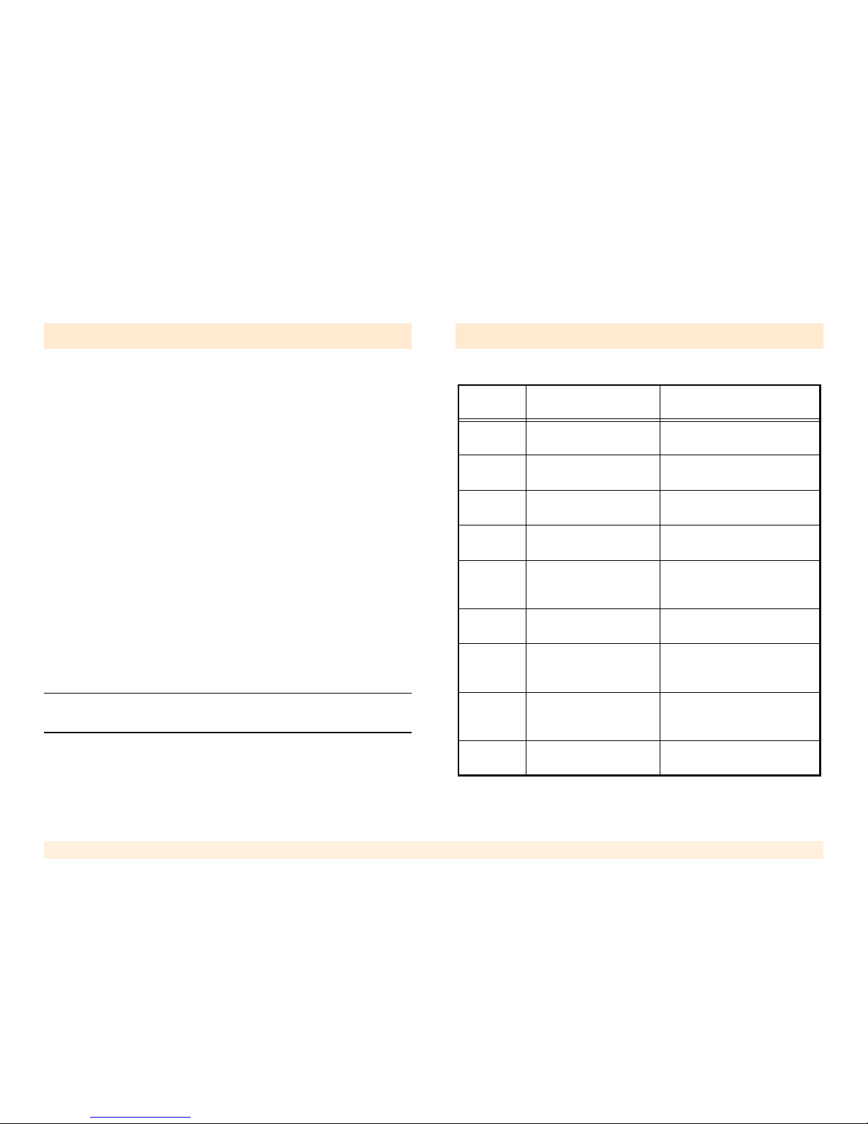
The iGATE FCT may be controlled remotely using SMS
commands. The SMS message must match the structure
described in tables Table 6 and Table 7. Both lowercase
and uppercase entries are acceptable.
Replies are returned to the originating phone number.
Once received, the iGATE FCT analyzes the message
and executes the command.
There are two types of commands:
GET command
GET commands request current information from the unit.
GET commands are a combination of three letters as
described in Table 6.
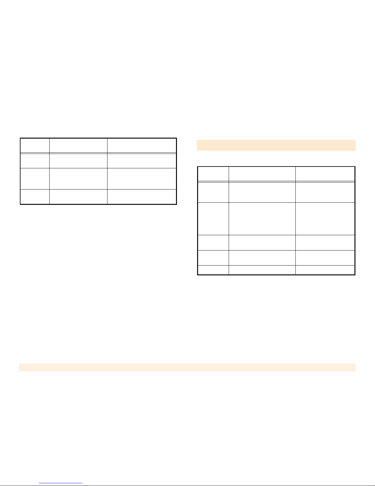
SET command
SET commands—defined in T able 7—apply programming
changes to the unit. SET commands are a combination of
three letters followed by the "=" sign and the corresponding programming feature.
Note: The speed SMS messages are delivered is dependent upon
the network. There may be a delay.
GET Command Table
Table 6: GET Command Table
Command
Syntax
Command Feature Applicable Response
LIS
Gets the line's current
state
LINE IS ONHOOK/OFFHOOK
SME
Gets the IMEI number
of the SIM
SIM IMEI No.: "Usually 20
digit number"
SMS
Gets the IMSI number
of the SIM
SIM IMSI No.: "Usually 15
digit number"
MME
Gets the IMEI number
of the cellular Module
MODULE IMEI No.: "Usually
15 digit number"
MSW
Gets the software version of the cellular module
Module SW Version: "As
defined by the cellular module manufacturer"
RXL
Gets the reception level
in DB
RX Level: (-51db – -113db)
dBm, BER:(0-7)
SWV
Gets the software version of the unit
SW VER: Q111xxxxxx
(Where xxxxxx states the
software version)
TRS
Gets the Toll Restriction
table
TR IS OFF/ON, xx,xx,xx,xx
Stored (Where xx defines the
TR prefix table)
VGR Gets the Rx Audio gain
RECEIVE GAIN (+30 - +51)
intervals of 3db
Page 26
TELES iGATE FCT User’s Guide 23
Previous Page Table of Contents Next Page
SET Command Table
VGT Gets the Tx Audio gain
TRANSMIT GAIN (+6 - -24)
intervals of 2 db
CEL
Gets the current registered cell information
Main Cell is: "Response
depends on the GSM Network"
SIG
Gets the signalling
method
Line Signal is Reverse Polarity/Pulse Drop, XX
Table 6: GET Command Table
Command
Syntax
Command Feature Applicable Response
Table 7: SET Command Table
Command
Syntax
Command Feature Applicable Response
SIG=P
Set Signalling method to
Pulse Drop.
Line Signal is: Pulse
Drop, XX (Where XX is
the width of the pulse)
SIG=P,XX
Set Signalling type to Pulse
Drop and the Length of the
pulse. Where XX can be 199 (100 milliseconds to 9.9
seconds)
Line Signal is: Pulse
Drop, XX (Where XX is
the width of the pulse)
SIG=R
Set Signalling type to
Reverse Polarity
Line Signal is: Reverse
Polarity
EMB=1
Erase the SMS inbox of the
SIM
Mailbox is Erased
RST=1 Reset the unit Restart Was Done.
Page 27

TELES iGATE FCT User’s Guide 24
Previous Page Table of Contents Next Page
Chapter 5
Miscellaneous
This section includes:
• “Call Progress Tones” on page 25
• “LED Indications” on page 25
• “Troubleshooting” on page 26
• “Specifications” on page 27
Page 28
TELES iGATE FCT User’s Guide 25
Previous Page Table of Contents Next Page
Call Progress Tones
LED Indications
Type ON cadence OFF cadence Remarks
Dial tone Continuous
Busy tone 0.5 Sec 0.5 Sec
Error tone 0.2 Sec 0.2 Sec
Distinctive tone 0.2 Sec 0.1 Sec
Incoming ring in
off-hook, before
dialling started
Confirmation tone
(for programming)
0.4 Sec 0.1 Sec 3 beeps
Rejection tone
(for programming)
0.4 Sec 0.1 Sec 2 beeps
RCPT LVL (Reception Level)
Indicates the
reception level
of the
iGATE
FCT
.
Green High reception.
Orange Medium reception
Red Low reception
Off Very low, or no reception at all
Note: T o indicate proper activity of the channel while
idle, the LED turns off a few seconds every 15 seconds of operation. During a call, the indication is frozen at that which existed when the call started.
STATUS
Indicates the
channel operational status.
On The channel is handling a call.
Blinking (0.2S on, 0.2S off) - During ringing
Off The channel is idle.
Indications
Slow blinking (0.5S on, 0.5S off):
The channel is initializing following power up.
Fast blinking (0.1S on, 0.1S off):
No SIM card or an error has occurred in the PIN
code entry. The PIN code must be disabled or
the default PIN code 1234 must be entered.
Mostly on (0.5S on, 0.1S off)
Toll Restriction is activated
Special Indications
Blinking (0.3S on, 0.3S off)
During DTMF programming session
Blinking (0.2S on, 1S off)
During local PC session
POWER
Indicates the
status of the
power connection.
On-the channel is powered on.
Off-the channel is powered off.
Page 29

TELES iGATE FCT User’s Guide 26
Previous Page Table of Contents Next Page
Troubleshooting
No Problem Indications Solution
1
Unit does
not
respond
None of the
Pwr LEDs is
on, no dial
tone
- Reconnect the power cable,
switch off and on the main switch,
and check if the AC socket is live.
2
Unit does
not
respond
Stat LED
does not
stop blinking
- Reconnect the power supply
J
Unit does
not
respond
Stat LED
blinks fast
- Replace the SIM with a good SIM
that does not require PIN code
- Insert a SIM of another network
4
Bad or no
audio
Rcpt
(Reception)
LED red
- Wait a few minutes and try again
- Move antenna to a better location
- Replace antenna with another
antenna
5
No dial
tone
No dial tone
- Check telephony cable - Try
using another phone
6
Dial tone
does not
stop
Dial tone
continues
after dialling
first digit
- Use a different phone
- Reset the unit (reconnect the
power supply)
7
Can not
connect to
a destination
The channel responds
with an error
tone after
dialling
- Verify that you have a valid SIM
card
- Check that the destination does
not conflict with the toll restriction
table
- Disable toll restriction table
- Try using a SIM without PIN
8
Can not
connect to
a destination
The network sends
an error
message
Check that the number dialled is
not longer than specified by immediate dialling
9
Voice level
is too low
or too high
Reprogram the voice levels
10
Calls longer than a
certain time
are cut
Call is cut
before going
on hook
Check that call duration is not too
short
An attempt
to change
the PIN
code fails
A rejection
tone is
heard
See “PIN Code Programming” on
page 16.
No Problem Indications Solution
Page 30
TELES iGATE FCT User’s Guide 27
Previous Page Table of Contents Next Page
Specifications
* Specifications are subject to change without notice
General Specifications
Mains Supply Voltage 100-240 VAC, 50-60 Hz
Current Consumption 0.5 A max
Operating temperature 0 °C to 45 °C
Physical dimensions 1U 19" shelf
Standards Full CE
Line Specifications (for each of the channels)
Line loop current 40 mA max
Line supply voltage - 48 VDC ± 10%
Line impedance 600 Ohm
Dial tone 400 Hz ± 1%
Ring generator 42 Vrms/25 Hz
Line signaling DTMF
Line connector (2W
TIP/RING)
RJ11-C (pin 2, 3- TIP, pin 4, 5- RING)
Data Port Specifications
Interface port RS232
Protocol AT Command Compatible
GSM Channel Specifications
Dual band GSM 900/1800Mhz or 850/1900MHz
Standards Type Approval CE mark.
GSM module WaveCOM Wismo 2D
Optional Features
Fax
Requires a data connection between the
iGATE FCT and a PC with Winfax
version 10 and up.
SMS
Requires a data connection between the
iGATE FCT and a PC running an
SMS application that supports WaveCOM module.
Safety Standards
N°QUAEMC_EN. 15967C
Conforms to the EMC requirements of:
EN 301 489-1 V1.4.1: 2002; EN 301
489-7 V1 .2.1: 2002, R&TTE Directive
1999/5/EC and EMC Directive 89/336/
EEC Article 4.
N°QUAS AF_EN. 15967C
Conforms to the Safety requirements of:
EN/IEC 60950-1:200 1and AS/NZ
60950.1:2003
 Loading...