

Telereef TR1D User Manual
Telereef Controller - User Manual V.140313!
!
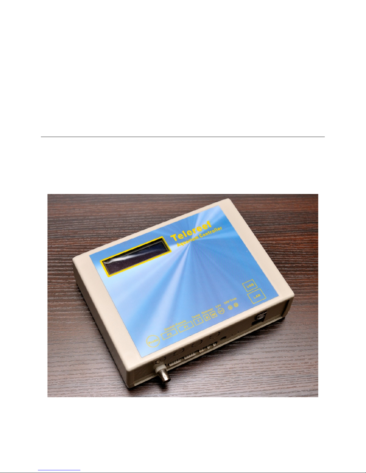
Telereef
Aquarium Controller Model: TR1D
User Manual!
1

Telereef Controller - User Manual V.140313!
Telereef Controller - User Manual
!
Table of contents
!
Understand your Telereef Controller! 3!
First Time Setup! 4!
Mount the Telereef Controller! 4!
Obtain IP Address and set up system time! 4!
Understand Web Interface and Setup System Time/Date! 4!
Setup an internal fixed IP address and new password! 5!
Setup Temperature Probe! 6!
Setup pH Probe! 6!
Adjust 10V dimmer output! 7!
LCD Display! 8!
Date and Time page! 8!
Sensors Page! 8!
Dimmers & Sockets status page ! 8!
System information! 8!
Further Setup! 9!
Relay Module & Socket Panels! 9!
Temperature controller for chiller and heater! 10!
pH controller! 10!
Timers! 11!
Wireless Dosing Pumps! 13!
Alert and Push notification (Prowl / Notify)! 13!
Settings Export/Import and Micro SD Memory! 14!
FTP server for logs backup! 15!
Log format! 15!
Aquarium live image (IP Cam)! 16!
Trusted IP! 17!
Wireless Network Connection! 17!
Factory Reset and Network Reset! 18!
Firmware update! 18!
If problem persists, please contact us at info@telereef.com for help.! 19!
Set WDP in pair mode! 19!
Details of Telereef’s Web interface! 20!
Home page! 20!
Setup page! 21!
Timer Settings page! 23!
System settings! 25!
Socket name settings! 26!
Temperature settings! 26!
pH Sensor settings! 27!
Wireless Dosing Pump Pair Screen! 27!
Wireless Dosing Pump Setting Screen! 27!
2
Telereef Controller - User Manual V.140313!
Understand your Telereef Controller!
!
Thank you for choosing Telereef Controller. Telereef Controller is a low cost but powerful
and easy to use aquarium controller, specially designed for both DIY and professional
aquarium projects. With Telereef Controller, you can control and monitor your aquarium
with a Smart Phone even you are on the other side of the planet. Timer schedules setup,
brightness control of LED lighting, pH value monitoring, temperature monitoring, precise
temperature control (with optional relay sockets), electric cost estimation, dosing additives
(with optional Wireless Dosing Pump), even you can know how much additive remains for
each dosing pump and provides push notification remind you to refill.
!
The central processing unit of Telereef Controller is ATmega2560 micro controller which
provides 256KB programming memory and 8K SRAM for running Telereef Firmware.
Beside these on board memories, Telereef Controller also has a 2GB SD memory which
used to keeps sensors logs and system settings.
!
Telereef Controller integrated with Ethernet Module which provides network connectivity,
able to connect to any existing router out of box. Beside network connectivity, Telereef
Controller also provides 2.4GHz RF wireless connectivity, able to connect to Telereef
Wireless Devices totally freedom, such as Telereef Wireless Dosing Pump TRWDP-S1 and
other upcoming Telereef Wireless Devices.
!
To achieve accurate and stable pH reading, Telereef Controller integrated with Atlas
Scientific pH Circuit which provides continually pH measurement to the aquarium with one
touch calibrating feature.
!
Please follow “First Time Setup” section to setup your Telereef Controller. You may need to
do a Network Reset if the Telereef Controller was ever connected to other network, please
refer to “Network Reset and Factory Reset” section about how to do a Network Reset.
!
Telereef Controller comes with the following accessories
!
- Dimmer Voltage Adjustment Cable x 1
- Network Cable x 1
- Small Screwdriver for Dimmer 10V Trim x 1
- System / Network Reset Plug x 1
- pH Sensor Probe x 1
- Temperature Sensor with 3 meter cable x 1
- 12V 2A DC Power Adapter x 1
- Self-Stick Reclosable Fasteners x 1 pair
!
!
*Life time update - We will provide firmware update as long as the product is still selling in market.
3

Telereef Controller - User Manual V.140313!
First Time Setup!
!
•
Mount the Telereef Controller!
!
Telereef Controller comes together with one pair of Self-Stick
Reclosable Fasteners, you can use it to mount Telereef Controller
somewhere on aquarium cabinet. Clean both surfaces before stick it
on.
!
This reclosable fasteners is very strong, you may consider to cut it
into two small pieces and stick them on two corners on the back of
Telereef Controller for easy removing.
!
•
Obtain IP Address and set up system time!
!
Because of simplified no button design, the only way to set up Telereef Controller is
through the Telereef’s Web Interface. First thing to do is find out how to connect to
Telereef Controller through the network connection.
!
1. Connect Telereef’s LAN port to one of the LAN ports on your router. !
(Telereef Controller can be connected wirelessly by using a small Traveller Nano
Router, please refer to Wireless Connection section for details.)
2. Connect Telereef’s DC port to a 12V 2A DC power adapter.
!
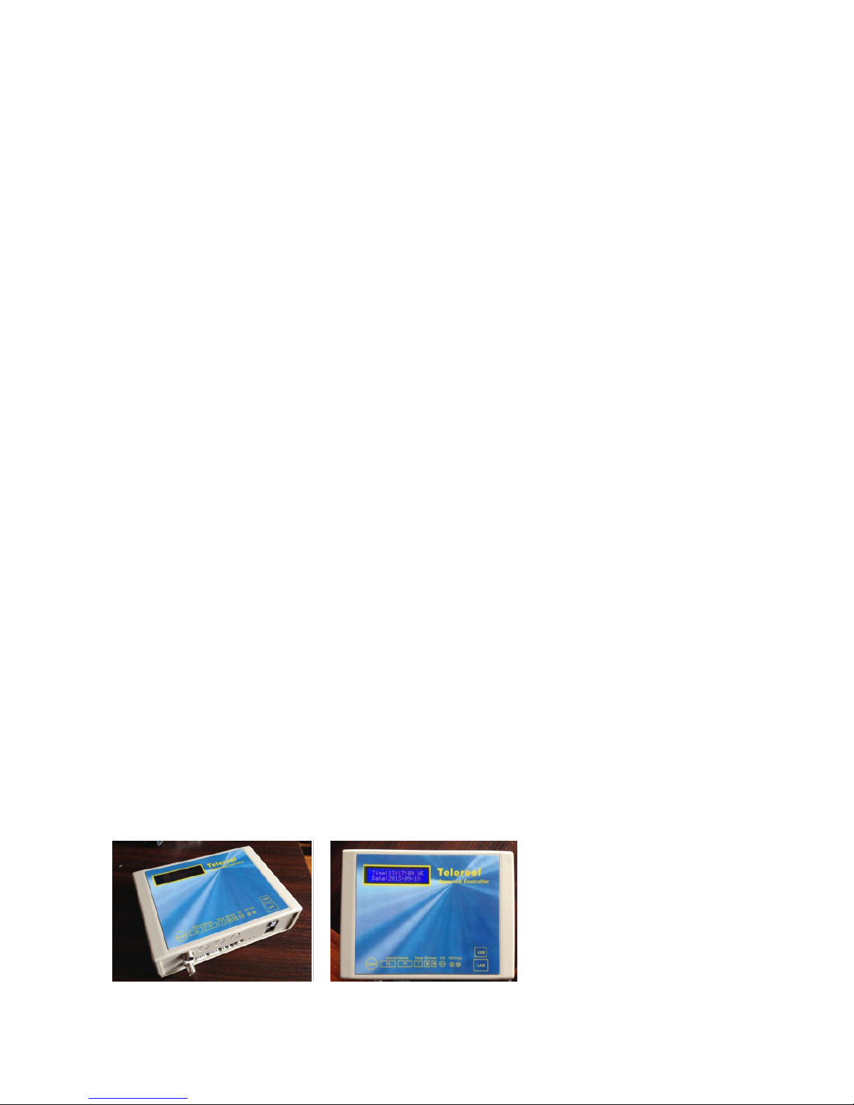
3. After connected DC power the LCD backlight will light up, and firmware version will
be displayed, now Telereef Controller is trying to obtains an IP address from the
router, the IP address will be displayed after a few seconds, please write down this
IP address for future use.!
! !
!
!
•
Understand Web Interface and Setup System Time/Date!
"
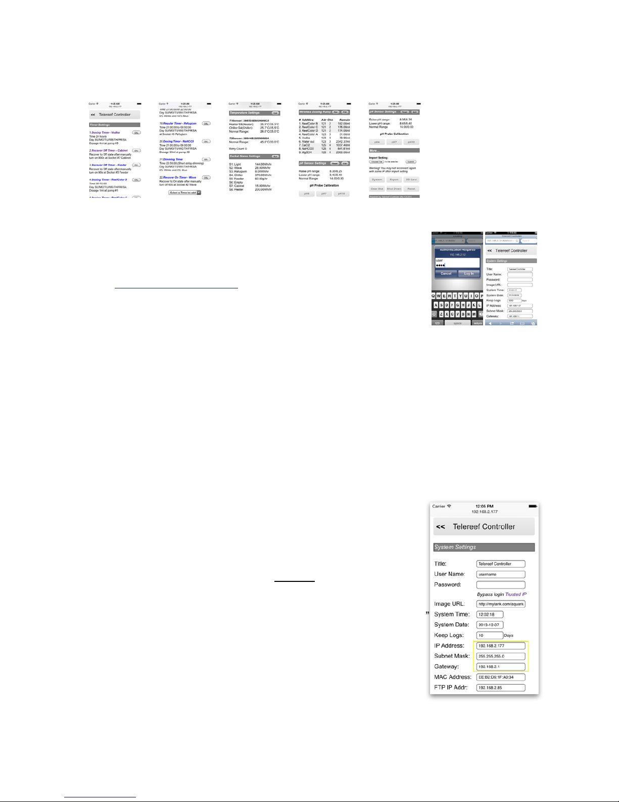
There are two main pages on Telereef’s Web Interface, they are Home page and Setup
page. Home page is used to present sensors information, socket status, socket manual
on/off, wireless dosing pump status, manual dosing control, usage statistic, etc.!
!
!
!
!
!
!
!
!
4
Telereef Controller - User Manual V.140313!
Push Setup button at the bottom of Home page will move to Setup page. In Setup page
you can set up timers, define socket name, pair wireless dosing pump, set up system
preference, etc.!
!
!
!
!
!
!
!
!
Follow the below steps to connect to Telereef Web Interface!
!
1. Use Smart Phone’s or Desktop computer’s Internet browser to
browse the IP address with port 8085. For above example, if
the IP address is 192.168.2.12, input !
http://192.168.2.12:8085 to the browser's address bar.
2. User Name & Password screen will display, input default user
name “user" and default password “user" (without quotes).
3. Scroll down to bottom of the Home page, push Setup button.
On the Setup page, scroll down to the end and push System button.
4. In the System page there are many things can be set, first thing we need to set is
System Date and Time. The System Date and Time fields are automatically filled
with your Smart Phone’s or Desktop computer’s date and time, simply push Save
button and the current date and time will be updated.!
!
•
Setup an internal fixed IP address and new password!
"
From the previous step, the IP address obtained from the router is a dynamic IP address,
which means that it may be changed or occupied by other computer from time to time,
there will be a chance you may be unable to connect to Telereef Controller with the same
IP address later, so it is better to use a fixed IP address instead.
!
1. Check the DHCP range of the router, DHCP range means a
range of IP address that the router assigns automatically; for
example 192.168.0.2 to 192.168.0.50. Usually the DHCP
range can be found inside router’s setup panel. Please refer to
the router user manual for details.
2. Choose an IP address which is outside the DHCP range, for
example 192.168.0.101
3. Go to System Settings page, change the field “IP address”
with the chosen IP Address on step #2, change “Subnet Mask”
if necessary, default is 255.255.255.0, change the “Gateway”
to router’s LAN IP address if it is not correct.
4. Change the “User Name” to the login name you preferred and
change the “Password” to a new password.
5. Push “Save” button to save the settings.
!
If you forgot the password or a wrong IP address has been used then you may not able
to connect to Telereef Controller any more, the only way to fix it is perform a system reset
5
Telereef Controller - User Manual V.140313!
by using the reset plug on P1 or P2 port; however, all settings will be erased. Please
refer to Factory Reset and network reset section for details.
!
To connect Telereef Controller from outside network through Internet, Port Forwarding or
Virtual Server is needed to be setup on the router on TCP port 8085, please refer to the
router manual for details.
!
•
Setup Temperature Probe!
"
There is a temperature sensor on Telereef main board; it used to report the internal
temperature of Telereef Controller to prevents overheating problem. The temperature
which is display on Home page is referred to the internal temperature sensor before an
external temperature probe has been setup.!
!
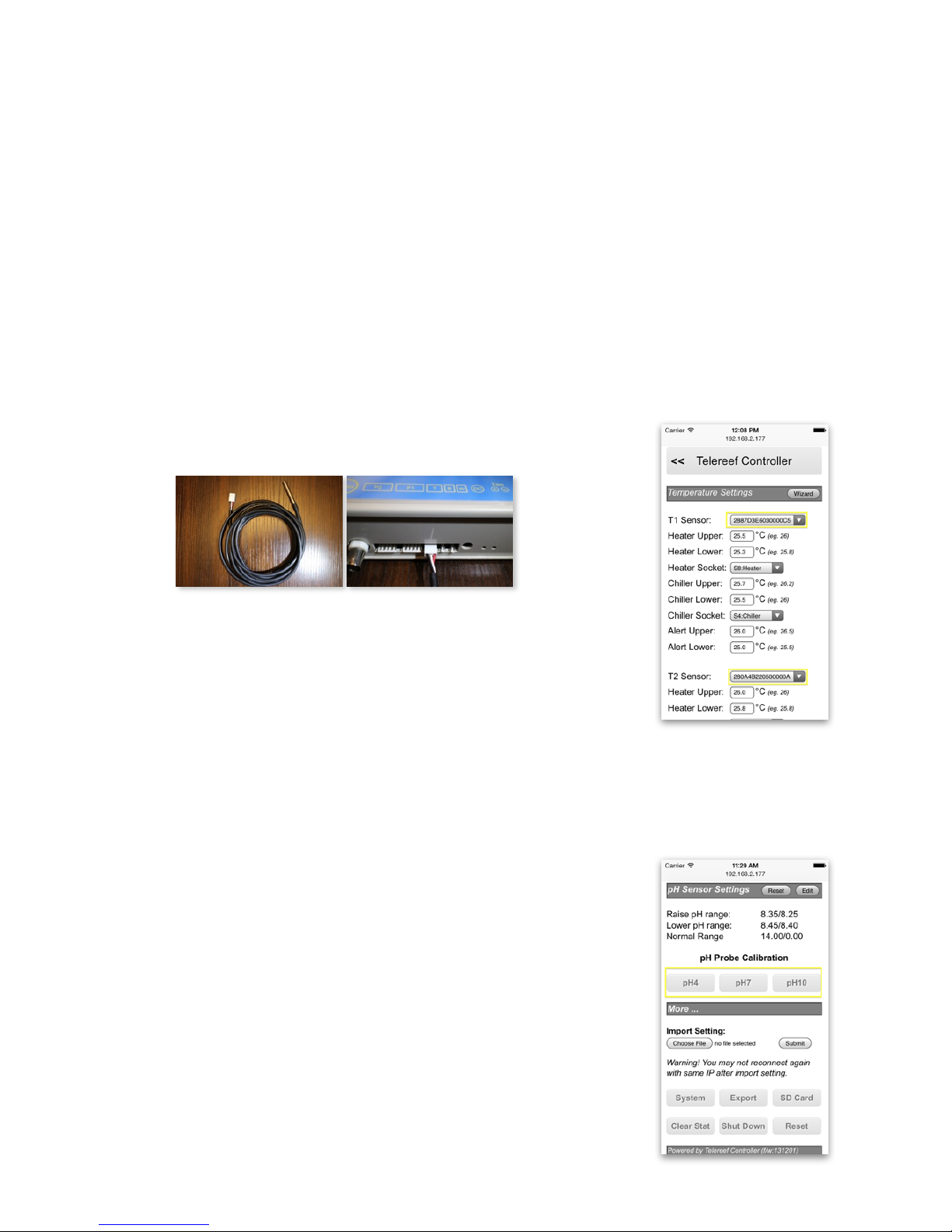
To setup external temperature probe!
a. Unplug the DC power from Telereef Controller
b. Plugin external temperature sensor to the three pins “T” port,
reconnect the DC power and wait for Telereef started up.!
! !
c. On Setup page, push “Edit” on Temperature Settings section.
d. At “T1 Sensor” select the address of the external temperature
sensor, if the address is not inside the pull down menu,
please reload this Temperature Settings page and try again.
e. At “T2 Sensor” select the address of the internal temperature
sensor.
f. Push “Save” button to save the settings.
!
Now, the big temperature reading on Home page changed shows the temperature of the
external temperature sensor. The temperature of internal temperature sensor can also
be found at the Sensors section of Home page.
•
Setup pH Probe!
"
A new pH probe need to be calibrated before use. To calibrate a
pH probe
!
1. Connect the pH probe to the Probe port
2. On Home page, make sure the pH value is not “N/A” (N/A
means AtlasScientific pH stamp is not installed).
3. Go to Setup page and scroll down to pH Sensor Settings
4. Raise the pH probe with RO water or Distilled water.
5. Dry the probe and put inside pH7 calibration solution, wait 2
minutes until the reading is stabled.
6. Push pH7 button and confirm the setting.
7. Raise the pH probe with RO water or Distilled water.
8. Dry the probe and put inside pH4 calibration solution, wait 2
6
Telereef Controller - User Manual V.140313!
minutes until the reading is stabled.
9. Push pH4 button and confirm the setting.
10.Raise the pH probe with RO water or Distilled water.
11. Dry the probe and put inside pH10 calibration solution, wait 2 minutes until the
reading is stabled.
12.Push pH10 button and confirm the setting.
!
•
Adjust 10V dimmer output!
"
Telereef TR1D provides two dimming channels for LED dimmable driver (eg. Mean Well
ELN-60-48D), one for White LEDs and one for Blue LEDs. Two dimming channels output
0 - 10V to controls the brightness of each channel. These dimming channels have been
factory adjusted 10V at 100% output before shipping; however, the output voltage may
need to be readjusted if different power adapter is used.!
!
(Skip this step if you don’t have a LED 0-10V Dimmable Driver at this moment)
!
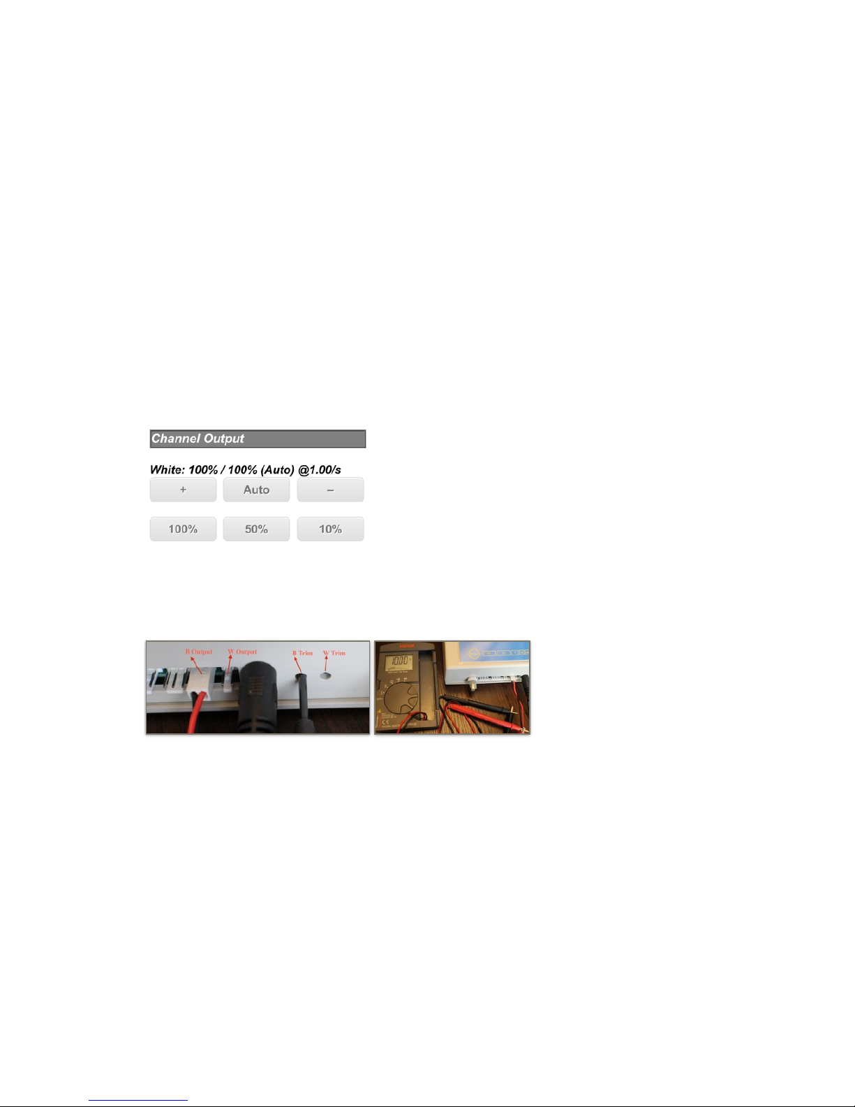
1. Go to Home page, push 100% button on White Channel, after the page refreshed
then push 100% button on Blue channel as well.!
!
2. Plugin Dimmer 10V Trim Cable to Dimmer Port “B”
3. Set multimeter to Voltage, connect Red line to multimeter’s positive “+” port, connect
Black line to multimeter’s negative “-” port.
4. Insert small screwdriver into 10V Trimer B hole, turn the screw inside until the voltage
reading is 10V.!
! !
5. Plugin Dimmer 10V Trim Cable to Dimmer Port “W”
6. Set multimeter to Voltage, connect Red line to multimeter’s positive “+” port, connect
Black line to multimeter’s negative “-” port.
7. Insert small screwdriver into 10V Trimer W hole, turn the screw inside until the
voltage reading is 10V
!
Congratulation ! Your Telereef Controller is ready to use.
!
7
Telereef Controller - User Manual V.140313!
LCD Display!
!
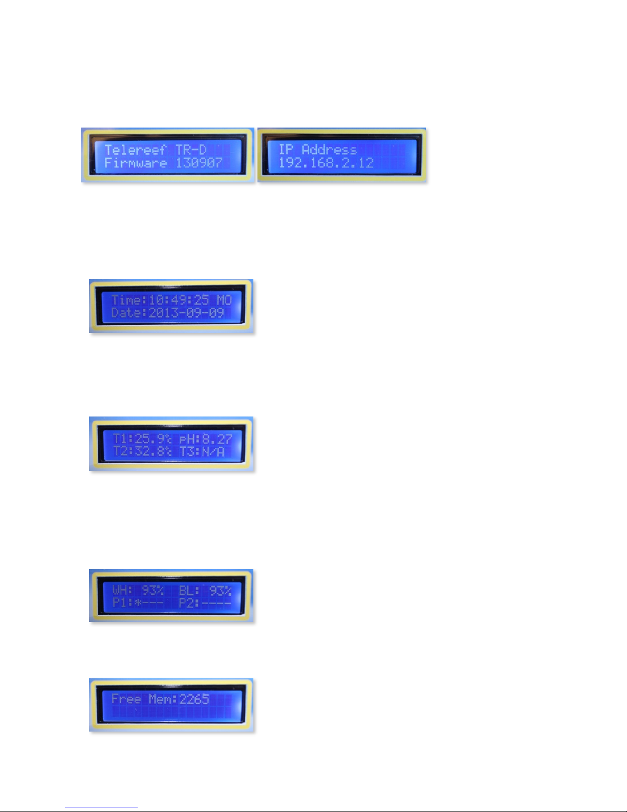
The LCD on Telereef Controller provides some useful information for both setup and daily
usage. When system starting, LCD shows model, firmware version and IP Address.!
!
! ! !
!
After system started, LCD cycling 4 pages with different information
!
•
Date and Time page!
"
First page of LCD display shows system time and date. If the time or date is not correct,
please go to Setup page, push System button and update the time and date.!
! !
!
•
Sensors Page!
"
Second page of LCD display shows three temperature probe reading and pH value. An
up “↑” arrow or down “↓” arrow indicates raising or lowering socket control is activated, or
"!" Indicates the value is out of safety range.!
! !
!
•
Dimmers & Sockets status page !
"
Third page of LCD display shows current output level of two dimming channels and
status of eight relays/sockets. P1 is corresponding to relays/sockets S1 - S4, P2 is
corresponding to relays/sockets S5 - S8. Socket with status On has an indicator “ * ” on
it’s position, status Off has an indicator “-” instead.!
!
!
•
System information!
!
Last page of LCD display shows some system information, e.g. free memory, IP.., etc.!
! !
!
8
Telereef Controller - User Manual V.140313!
Further Setup"
!
•
Relay Module & Socket Panels!
"
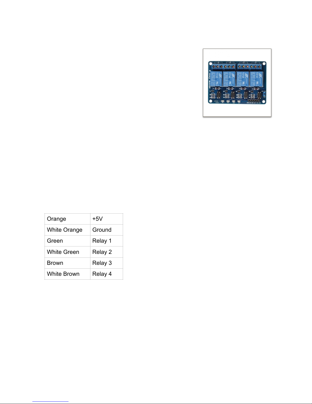
Two 4-Channel relay modules can be connected to Telereef
Controller through P1 and P2 port, totally eight relays can
be use to control eight electrical devices. Most 5V 4Channel relay modules in the market which is compatible
with Arduino are also compatible with Telereef Controller.
There is 5V output from P1 and P2 port which can supply
relay module without external power supply.!
!
Normally, this kind of relay module is good and safety for
low voltage DC devices, however if you are going to
connect high voltage AC or high power devices should be careful, such as chiller, heater,
etc. You should have enough knowledge, and related qualification to connect relay
module to AC powered device and should be very careful when connecting, good
isolated is also very important; otherwise, serious electrical shock or fire may
occur. Make sure the relay has enough rating to controls the device."
"
You can connect Telereef Controller to Relays/Sockets module with a signal cables. You
can purchase this cable from our reseller, or make it by yourself easily. Most Relay
Modules in the market have a six pins connector which is compatible with KF2510 plug,
just install six pins KF2510 plug on both ends of the cable, one end is plug into P1 or P2
port, the other end is into the relay module. !
!
The color coding of the signal cable is!
!
The signal cable should be keep away from AC line to prevent interference.
!
Some mechanical relays may not go back to off state after turned on for a long
period of time continually, you should beware of this especially if you use it to
control aquarium temperature or dosing device. "
"
Once your socket panel is ready, next step is setup socket name!
!
1. Go to Setup page, scroll down to Socket Name Settings and push Edit button.
2. Input the Name of the device connected, Rating/Usage and Unit.
3. Push Save button to save the setting.!
!
!
Orange
+5V
White Orange
Ground
Green
Relay 1
White Green
Relay 2
Brown
Relay 3
White Brown
Relay 4
9
Sainsmart 4-Channel 5V
Relay Board
 Loading...