

Tele Radio T60
INSTALLATION INSTRUCTION/
INSTALLASJONSINSTRUKSJONER
FOR T60TX-15DML TRANSMITTER
IM-T60-TX001-A11
ENGLISH (ORIGINAL LANGUAGE)
+ NORWEIGAN
(TRANSLATION OF ORIGINAL)
ENGELSK (ORIGINAL)
+ NORSK
(OVERSETTELSE AV ORIGINAL)


3
Thank you for puchasing a Tele Radio product
T60TX-15DML
READ ALL INSTRUCTIONS CAREFULLY BEFORE MOUNTING,
INSTALLING AND CONFIGURATING THE PRODUCT.
These instructions are published by Tele Radio AB without any guarantee.
These instructions are solely directed towards qualied installers. The
information shall not be handed to end users. The instructions may be
removed or revised by Tele radio AB at any time and without any further
notice. Corrections and additions will be added to the updated versions
of the instructions.
The instructions that contain information on the installation and cong-
uration of the remote radio control unit on the machine are not intended
to be passed on to the end user. Only such information may be passed on
to the end user, that is needed to operate the machine correctly by radio
remote control.
Tele Radio AB products are covered by a guarantee against material, construction or manufacturing faults. During the guarantee period, Tele Radio
AB may replace the product or faulty parts with new. Work under
guarantee must be carried out by Tele Radio AB or by an authorized
service centre specied by Tele Radio AB. Make sure that repairs and
maintenance are only carried out by qualied personnel. Use only spare
parts from Tele Radio AB. Contact your Tele Radio representative if you
want to make a complaint about a product or require other service.
©Tele Radio AB, 2010
TELE RADIO AB
Datavägen 21, SE-436 32 Askim. Sweden
Tel: +46 (0)31-748 54 60
Fax: +46 (0)31-68 54 64
www.tele-radio.com.
info@tele-radio.com
The helpdesk group can help you with questions
regarding service and technical support.
helpdesk@tele-radio.com

4
CONTENTS/ INNHOLD:
ENGLISH: Installation instructions 4
NORSK: Installasjonsinstruksjoner 27
EC declaration of conformity/ Samsvarsærklering 46
Appendix 47

5
CONTENTS
SAFETY INFORMATION 6
TRANSMITTER 8
T60TX-15DML 8
PROGRAM A SHORTCUT 8
RECEIVER 9
PLACE ANTENNA AND RECEIVER 9
CODE LEARNING 9
T60RX-04#SL 10
T60RX-08#SL 11
T60RX-03ADL- DIN 14
T60RX-01APL/ T20RX-01APL 16
T60RX-01ARL/ T20RX-01ARL 17
LATCHING, INTERLOCKING & RESETTING 19
REPLACE A 460 TRANSMITTERS 21
TROUBLE SHOOTING 23
BATTERY 24
DISPOSAL AND RECYCLING 24
GUARANTEE, SERVICE, SUPPORT & REPAIRS 25
DIRECTIVES AND STANDARDS 25
DECLARATION OF CONFORMITY (EC) 49
APPENDIX 50

6
SAFETY INFORMATION
Read the instructions carefully before mounting, installing, congurating
and using the product.
• Allow only qualied personnel to install the product. Switch the power
supply off before connecting.
• Use undamaged cables. No cables should hang loose.
• Place the receiver well away from wind, damp and water with cable
glands and vent plugs faced down.
• Make sure that the user has reached the certied age to operate the
equipment and isn´t under the inuence of drugs, alcohol and
medicines.
• Make sure that the user does not leave the transmitter unsupervised,
always turns the transmitter off when not in use and keeps a good
overview of the work area.
• Contact your representative for service and maintenance work.
• Write down the serial numbers of the receivers and transmitters used.
• Avoid registering transmitters to receivers where it is not being used.
• The system works at frequency 433.92 MHz. and uses frequency
modulation: FM. FM is less sensitive to the electrical interference
generated in computers, electric motors etc. than AM.
• Objects positioned between the transmitter and receiver antenna,
e.g. large metal objects (such as reinforcement rods in concrete walls),
can affect the range, depending on the distribution of radio signals.
• The inuence of other radio transmitters on the same frequency in the
vicinity also affects the range. Due to these circumstances it is difcult
to give any general advice other than that free visibility between the
transmitter and the receiver should produce the best range with an
optimal signal.
• The normal range in an interference-free environment is approx.
50-100 m.
According to the Machinery Directive 2006/42/EC we recommend a
wired emergency stop where applicable, as well as other protections
against personal injuries, e.g. pinch protection for sliding car doors. The
radio control system should only be used for Functions such as starting
and halting of an application. The radio control system must not be a
safety-related part of a control system.

7

8
460 SYSTEM COMPATIBLENESS
The transmitter T60TX-15DML can be made compatible with the 460
system by using the system switch. See transmitter overview for
instructions.
9
*NOTE! The transmitter must be off to make a reset.
PROGRAM A SHORTCUT
The *-button and the #-button can be used to program a shortcut
(1 shortcut per button) for a particular function:
1. Set the door that you wish to save.
2. Press * or # for more than 3 seconds (the display ashes when the
shortcut is saved).
3. To use the shortcut, press the programmed button.
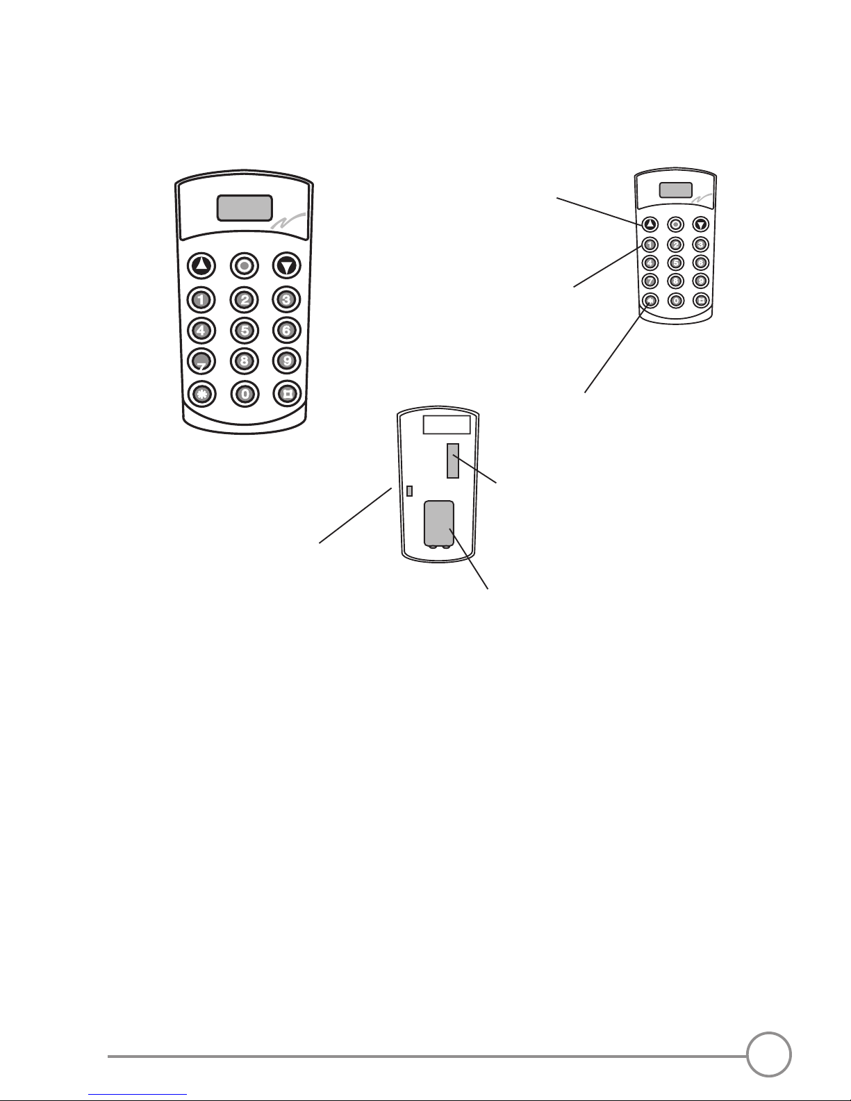
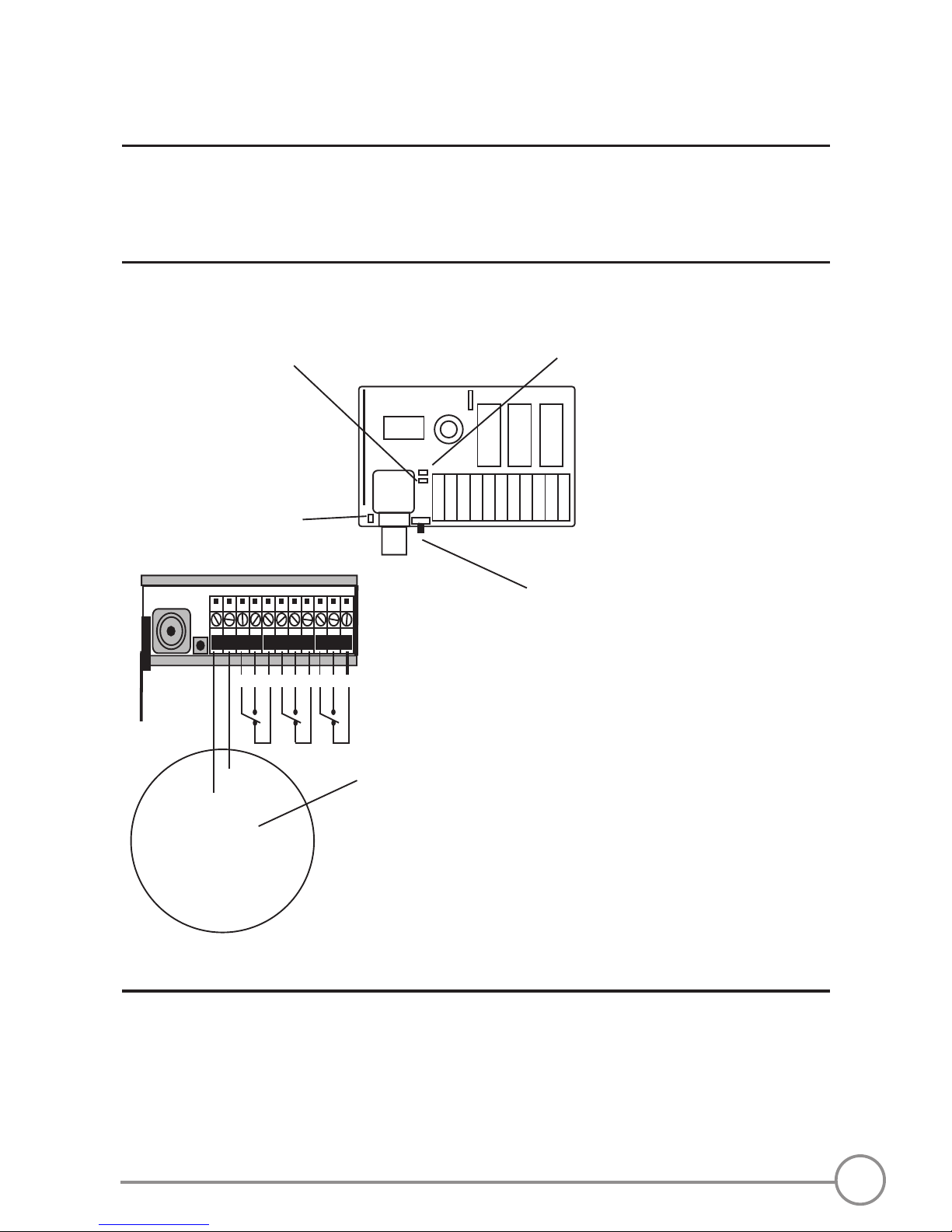
SYSTEM SWITCH (A1):
T60 system compatibleness: Put (A1) in ON position.
460 system compatibleness: Put (A1) in OFF position.
(B)
(A1)
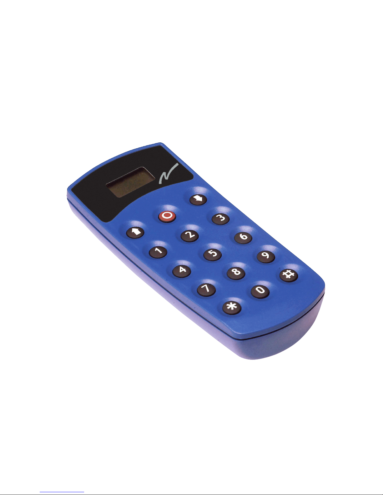
THE TRANSMITTER
T60TX-15DML
Size: 143 x 62 x 38 mm.
Function buttons
9V battery
Door no. buttons
Function shortcut
Code switch
System switch*
10
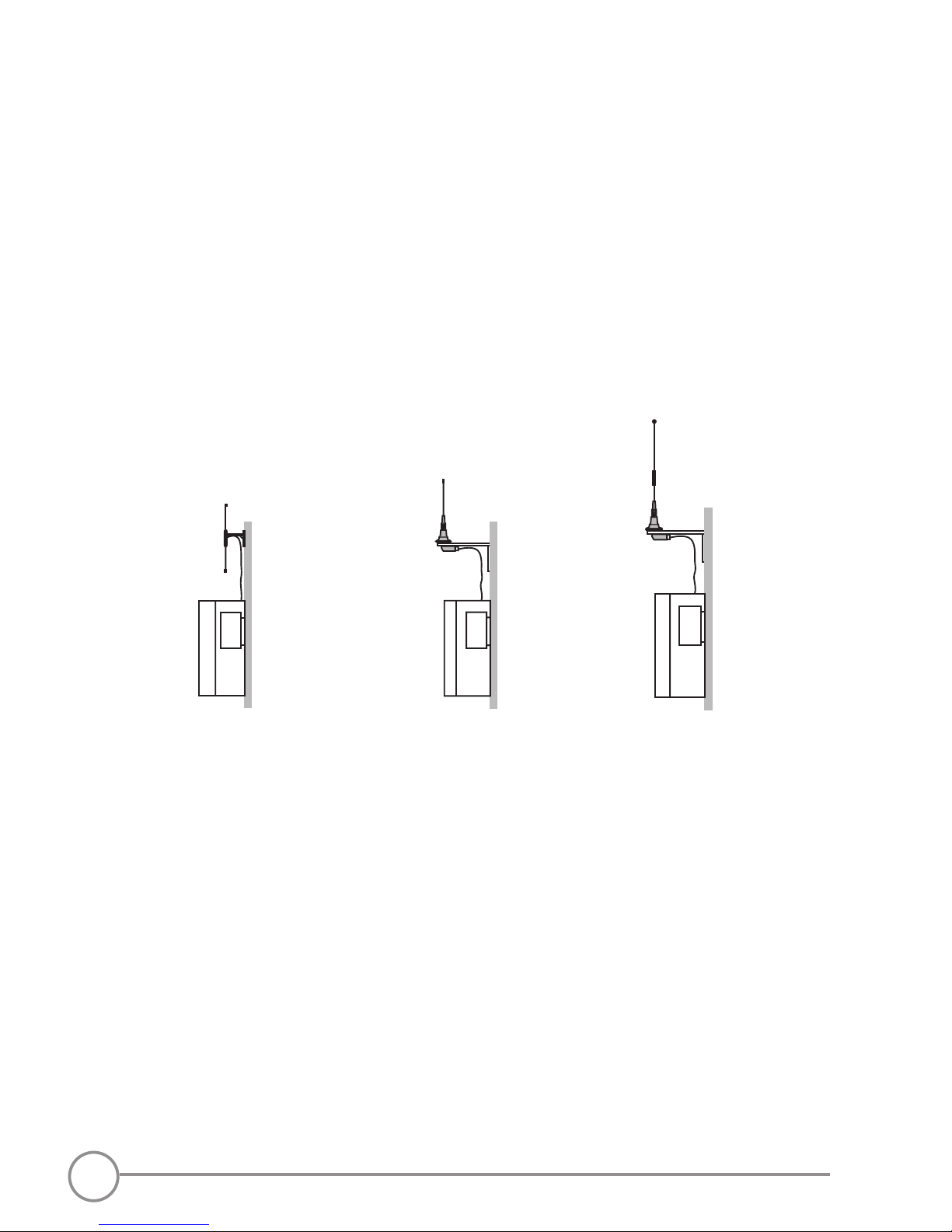
DIP-433K3
1/4-433Kx
5/8-433Kx
X= 3, 5 or 10 m. antenna cable
THE RECEIVER
PLACE ANTENNA AND RECEIVER
Place the receiver:
• As well protected from wind and water as possible.
• With the cable glands facing down to prevent water from seeping in.
Place the antenna:
• Place the antenna high above the ground.
• Avoid placing close to metal objects, such as electrical cables and
other antennas.
•
•
CODE-LEARNING
Transmitters and receivers must be co-programmed prior to use. Two
types of codes can be used with this transmitter:
Adjustable code:
The transmitter has a code switch with 10 three-position switches. There
are 59.049 codes available.
Fixed individual code:
The transmitter has a xed, individual code, that cannot be changed.
11
4
1
2
3
5
6
7
8
9
10
*
1 2 3 4 5 6 7 8 9 10 11 12
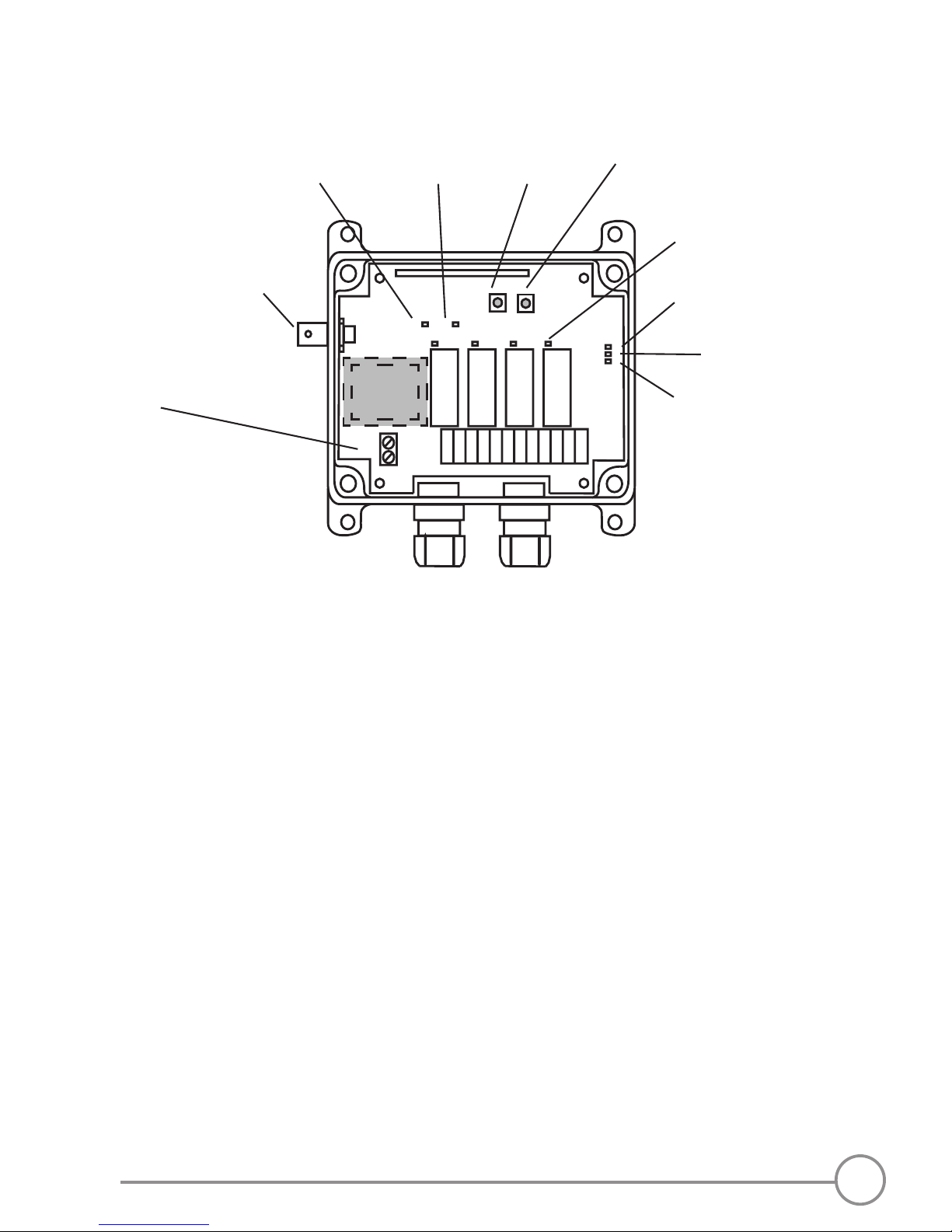
NOTE! For connecting the receiver, see Appendix D.
1. Yellow power LED lights: The receiver has the correct
supply voltage
2. Green radio LED lights: The receiver receives a radio
signal
3. Function button
4. Select button
5. Red relay LED lights: The relay is activated
6. Red LED 6 lights: Learning of code is possible
ashes: Adjustable code programmed
(1-10)
ashes twice: At least one xed,
individual codes is programmed
7. Yellow LED 7 ashes: At least one of the relays has a
latching function
8. Green LED 8 ashes: At least one of the relay-pairs
is interlocked
9. Connection terminal for voltage
10.BNC contact for the antenna
T60RX-04#SL

12
2
3
4
5
8
9
10
NOTE! For connecting the receiver, see Appendix D.
* TRAFO
1
6 7
T60RX-08#SL
Operating voltage 12-28 V AC / DC or 48 / 115 / 230 V AC
Size: 175 x 125 x 45 mm.
Protection: IP65
1. Yellow LED lights: The receiver has the correct
supply voltage
2. Green LED lights: The receiver receives a radio
signal
3. Function button
4. Select button
5. Red relay LED lights: The relay is activated
6. Red LED lights: Learning of code is possible
ashes: Adjustable code programmed
(1-10)
ashes twice: At least one xed,
individual codes have been programmed
7. Yellow LED ashes: At least one of the relays has a
latching function
8. Green LED ashes: At least one of the relays is
interlocked
9. Connection terminal for voltage
10.BNC contact for the antenna

13
PROGRAM T60RX-04#SL/ T60RX-08#SL
1. Press the Function button to scroll between the programming
options:
• Code learning (LED 6 lights red)
• Latching relay (LED 7 lights yellow)
• Interlocked relays (LED 8 lights green)
2. a. Press the Select button when LED 6 lights red if you want to enter
the Code learning mode (see next section).
b. Press the Select button when LED 7 lights yellow if you want to
assign a latching functionality to a relay (see the Latching relay
section).
c. Press the Select button when LED 8 lights green if you want to
assign interlocking to a relay-pair (see the Interlocking relay
section).
3. When done, press the Select button.
CODE LEARNING
Adjustable ID code
1. Enter the ID code that you want to assign to your transmitter (or
more than one transmitter) on the 10-pole transmitter code switch.
The receiver will catch up the same ID code when co-programmed.
2. Press the receiver Function button to select Code learning (LED 6
lights red).
3. Press the Select button (red LED 6 go out, the relay LEDs light red).
4. Press the receiver Function button to light up the LED above the
relay that you want to control.
• When you enter, all relays are selected by default and trans-
mitter button 1 controls relay 1, button 2 controls relay 2 etc.
• If you want to make other settings: Press the Function button to
step through the relays one by one. Select a relay by pressing the
Select button. When a relay has been selected, red LED 6 light
red. If it isn´t selected, red LED 6 isn´t lit.
5. When done, press the Select button.
6. Press the button that is to control the selected relay until LED 6
ashes red 3 times.

14
Fixed, individual (private) ID code
1. Press the Function button to select Code learning (LED 6 lights
red).
2. Conrm by pressing the Select button (the relay LEDs light red).
3. Press the receiver Function button to light up the LED above the
relay that you want to control.
• When you enter, all relays are selected by default and trans-
mitter button 1 controls relay 1, button 2 controls relay 2 etc.
• If you want to make other settings: Press the Function button to
step through the relays one by one. Select a relay by pressing the
Select button. When a relay has been selected, red LED 6 light
red. If it isn´t selected, red LED 6 isn´t lit.
4. Press the Select button for 0.3-4 seconds.
5. WITHIN 1 second: Press the Select button again for more than
1 second.
6. Press the button that is to control the selected relay until LED 6
ashes red 3 times.
Erase ID codes
1. Press the Function button to select Code learning (LED 6 lights red).
2. Conrm by pressing the Select button (the relay LEDs light red).
3. Press the Function button to scroll to the relay(s) that you want to
erase.
4. Press the Select button for more than 6 seconds until the LED(s)
above the relays go out.

15
RELAY SETTINGS FOR T60RX-04#SL, T60RX-08#SL
Latching relay functionality
NOTE! As a default the receiver relays are momentary.
1. Press the receiver Function button to select Latching relay (LED 7
lights yellow).
2. Conrm by pressing the Select button (the relay LED above relay 1
lights red).
3. If yellow LED 7 lights, the current relay is latching. If yellow LED 7
does not light, the current relay isn´t latching. Press the Select
button when the relay LED lights, if you want to assign a latching
functionality to that relay. If not, press the receiver Function button
to move to the next relay. The programming is completed when all
relays have been passed.
4. When done, press the Select button. Yellow LED 7 ashes to
indicate that at least one of the relays have a latching functionality.
Interlocking relay functionality
Interlocking can be set between relays:
• 1 and 2
• 3 and 4
• 5 and 6 (Robust receiver)
• 7 and 8 (Robust receiver)
1. Press the receiver Function button to select Interlocking relay (LED
8 lights green).
2. Conrm by pressing the Select button (the relay LEDs above relay
1 and 2 light red).
3. If green LED 8 lights, the current relay-pair is interlocked. If green
LED 8 does not light, the current relay-pair isn´t interlocked. Press
the Select button when the relay LEDs lights, if you want to assign
a latching functionality to that relay-pair. If not, press the receiver
Function button to move to the next relay-pair.

16
4. The programming is completed when all relay-pairs have been
passed.
5. When done, press the Select button. Green LED 8 ashes to
indicate that one or more relay-pairs are interlocked.
Reset
Press the Function button and the Select button at the same time for
more than 4 seconds to erase all codes, relay settings and functions. The
red, yellow and green LEDs + the red relay LEDs light until all settings are
erased.
17
12/24V AC/ DC
12/24V AC/ DC
C NO NC
C NO NC C NO NC
The green LED indicates
receiving of signals
Function button for code learning/
erasing
The red LED shows the programming
status
The yellow LED indicates
supply voltage
Connecting power
T60RX-03ADL/ T20RX-03ADL- DIN RECEIVER
Frequency: 433.92 MHz.
Operating voltage: 12-24 V AC/DC
Size: 86 x 30 x 58 mm.
Protection: IP 20 (internal installation)
NOTE! If simultaneous relay function, this priority applies:
Relay 1+2: Relay 2 has priority
Relay 2+3: Relay 2 has priority
Relay 1+2+3: Relay 2 has priority
Relay 1+3: No Function

18
Adjustable ID code
1. Enter the ID code that you want to assign to your transmitter (or
more than one transmitter) on the 10-pole transmitter code switch.
The receiver will catch up the same ID code when co-programmed.
2. Press the receiver Function button to select Code learning (LED 6
lights red).
3. Select a number between 000 and 999 that you want to assign to
the communication with the receiver. Enter the number on the
transmitter buttons.
4. Press any function button on the transmitter (i.e. up, stop, down)
until the red LED ashes 3 times.
Fixed, individual ID code
1. Press the receiver Function button to select Code learning (LED 6
lights red).
2. WITHIN 1 SECOND: Press the receiver Function button for more
than 1 second.
3. Press a transmitter function button (i.e. up, stop, down) until the red
LED ashes 3 times.
Erase ID codes
1. Press the receiver Function button for approx. 6 seconds until the red
LED lights up. When the memory is erased, the red LED goes out.
NOTE! All transmitter codes get erased at the same time.
CODE LEARNING (ADL)

19
5
6
11
10
The green LED indicates
receiving of signals
Function button for code
learning/erasing
The red LED shows the
programming status
The yellow LED indicates
the supply voltage
BNC connector
Side 1
Side 2
Voltage connection
11-pin terminal
5. 12-24 V AC/DC
6. 12-24 V AC/DC
10. NO
11. C
19
T60RX-01APL/ T20RX-01APL PLUG-IN RECEIVER
Frequency: 433.92 MHz.
Operating voltage: 12-24 V AC/DC
Size: 70 x 58 x 40 mm.
Protection: IP 23 (internal installation)

20
T60RX-01ARL/ T20RX-01ARL
Operating voltage: 12-30 V AC/DC
Power consumption: 40-80 mA.
Dimensions ARL: 54 x 63 x XX mm.
Climatic conditions: -30°C-+70°C
Humidity <95%
Transmitter compatibility: T20, T60, 460
1. Red LED shows programming status
2. Yellow LED lights up when the receiver has the
correct operating voltage
3. Green LED lights up when receiving a radio signal
4. Button Function button for code learning/
erasing
5. Relay maximum load over relay is 8 A for
resistive loads
6. Connection terminal for voltage
7. Connection terminal for relay
8. Antenna wire antenna
4
3
2
1
5
6
7
8
NOTE! For
connecting the receiver,
see Appendix G

21
CODE LEARNING (APL & ARL)
Adjustable ID code
1. Enter the ID code that you want to assign to your
transmitter (or more than one transmitter) on the
10-pole transmitter code switch. The receiver will
catch up the same ID code when co-programmed.
2. Press the receiver Function button to
select Code learning (LED 6 lights red).
3. Press any function button on the transmitter (i.e.
up, stop, down) until the red LED ashes 3 times.
Fixed, individual ID code
1. Press the receiver Function button to select Code learning (LED 6
lights red).
2. WITHIN 1 SECOND: Press the receiver Function button again.
3. Press a transmitter function button (i.e. up, stop, down) until the red
LED ashes 3 times.
Erase ID codes
1. Press the receiver Function button for approx. 6 seconds until the red
LED lights up. When the memory is erased, the red LED goes out.
NOTE! All transmitter codes get erased at the same time.

22
(A)
(B)
41 2 3 5 6 7 8 9 1 0
+
0
ON
1
REPLACE A 460 TRANSMITTER
T60TX-15DML replaces 401RVL9/ 403RVL9 transmitter with
knob 1-10
1. Put the transmitter switch (A) in position 1 (OFF).
2. Put the code switch 9 (B) in position 0 (zero) .
3. Put code switch 10 in minus or plus position, depending on whether
you are using A or B coding on the old transmitter (Robust transmitter).
4. Set codes (identical to the receiver codes) on the transmitter code
switches 1-4 (code switches 5-8 are not used).
5.Check that the relay is activated when one of the transmitter buttons
is pressed. The digits on the transmitter display correspond to the knob.
Press one gure followed by a transmitter button. Make sure that the
corresponding relay is activated.
See code table 1-10, Appendix A.

23
T60TX-15DML replaces 401RVL9 and 403RVL9 with knob 0-15
1. Put the transmitter system switch (A) in position 1 (OFF).
2. Put the code switch (B) 9 in -(minus) position.
3. Set code switch 10 either in minus or plus position, depending on
whether you are using A or B coding on the old transmitter (Robust
transmitter).
4. Set codes (identical to the receiver codes) on the transmitter code
switches 1-4 (code switches 5-8 are not used).
5. Make sure that the relay is activated when one of the transmitter
buttons is pressed.
See code table 0-15, Appendix B.
T60TX-15DML replaces a 460-93 transmitter
1. Put the transmitter system switch (A) in position 1 (OFF).
2. Put the code switch (B) 9 in +(plus) position.
3. Set codes (identical to the receiver codes) on the transmitter code
switches 1-3 (code switches 4-8 are not used).
4. Make sure that the relay is activated when one of the transmitter
buttons is pressed.
See code table 460-93, Appendix C.
NOTE!
When you select the door on the T60TX-15DML transmitter, enter a
combination of the rst digit and the last two digits, when it works
together with a 460-93 transmitter.
Example: Operate door A2 as in table A: Enter the combination 102
Operate door D3 as in table D: Enter the combination 403

24
-
INCORRECT FUNCTION POSSIBLE CAUSES ACTION
The receiver does not work when
you are
transmitting.
The receiver is
incorrectly connected.
Check the connection on
the receiver.
Incorrect
operating voltage to the
receiver.
Check the supply
voltage.
The green receiver LED lights up
when you are transmitting, but the
relays are not activated.
The transmitter and the
receiver are not correctly
co-programmed.
Follow the
instructions to
co-program the units.
The green receiver LED does
not light up when you are
transmitting.
The battery is dead. Replace the battery.
The transmitter is defective. Contact your
representative.
The green receiver LED lights up
when you are not transmitting.
Somebody is transmitting
in the vicinity on a similar
frequency.
Contact your
representative.
The transmitter’s LED does
not light up when you are
transmitting.
The battery is dead. Replace or charge the
battery.
The transmitter may be
defect.
Contact your
representative.
The range is too short. Poor battery. Switch the battery.
The antenna cables are
damaged or
incorrectly installed.
Check the antenna
connection.
TROUBLE SHOOTING

25
BATTERY
PRECAUTIONS
• Observe the following warnings.
As batteries contains ammable substances such as lithium or other
organic solvents, they may cause heating, rupture or ignition.
• Risk of explosion if battery is replaced with a battery of an incorrect
type.
• Do not short circuit, disassemble, deform or heat batteries.
• Never try to charge a visibly damaged or frozen battery.
• Do not charge rechargeable batteries with a higher voltage than
specied.
• Keep batteries out of reach of small children. Should a child swallow
a battery, consult a physician immediately.
• Avoid direct soldering to batteries.
• When discarding batteries, insulate the + and - terminals of
batteries with insulating/ masking tape. Do not put multiple batteries
in the same plastic bag.
• When improperly disposed, lithium batteries may short circuit,
causing them to become hot, burst or ignite.
• Store in a cool location. Keep batteries away from direct sunlight,
high temperature, and high humidity.
• Do not throw batteries into re.
DISPOSAL AND RECYCLING OF BATTERIES AND
ELECTRONICS
Improperly disposed batteries and electronics may
harm public health and the environment. Batteries
and electronic waste may contain toxic heavy metals.
If thrown away in the trash, the toxic compounds can
leach into soil and water, pollute lakes and streams,
making them unt for drinking, swimming, shing, and
wildlife. Contact your local government’s recycling
or solid waste department for more information on
proper recycling of electronics and batteries in your
region.

26
GUARANTEE
Tele Radio’s products are covered by a guarantee against material,
construction or manufacturing faults.During the guarantee period Tele
Radio may replace the product or faulty parts with new ones. Work under
guarantee must be carried out by Tele Radio or by an authorized service
centre specied by Tele Radio.
The following faults are not covered by the guarantee:
• Faults resulting from normal wear and tear.
• Parts of a consumable nature.
• Products that have been subject to unauthorized modications.
• Faults resulting from incorrect installation or use.
• Damp or water damage.
SERVICE, SUPPORT & REPAIRS
Make sure that repairs and maintenance are only carried out by qualied
personnel. Only use spare parts from Tele Radio. Contact a Tele Radio
representative if you need support or require other service.
OPERATING GUIDELINES
• Keep the product in a dry, clean place.
• Make sure that contacts and antennas are kept clean.
• Wipe off dust using a slightly damp, clean cloth.
• Never use cleaning solutions or high-pressure water.
DIRECTIVES AND STANDARDS
This product complies with current European directives and standards.
0678

27
INSTALLASJONSINSTRUKSJONER
INHOLD
SIKKERHETSINFORMASJON 29
SENDER
HURTIGVALG AV EN FUNKSJON 31
MOTTAKER
ID-KODER 32
T60RX-04#SL & T60RX-08#SL 33
REGISTRERE ID-KODER 34
VEKSLENDE RELÉFUNKSJON 36
FORRIGLINGSFUNKSJON 36
T60RX-03ADL/ T20RX-03ADL- DIN 37
REGISTRERE ID-KODER 38
T60RX-01APL/ T20RX-01APL- PLUGIN 39
T20/T60RX-01ARL 40
KOMPLETTERING TIL 460-SYSTEMET 41
FEILSØKINGSSKJEMA 43
BATTERI 44
GARANTI 44
FORHOLDSREGLER 44
CE DEKLARATION 44
KASSERING AV ELEKTRONIKK OG BATTERIER 44

28
Takk for at du anskaffer et Tele Radio produkt
T60TX-15DML
LES ALLE INSTRUKSJONENE NØYE FØR DU MONTERER,
INSTALLERER OG KONFIGURERER PRODUKTET.
Disse instruksjonene er utgitt av Tele Radio AB uten noen garanti. Disse
instruksjonene er kun rettet mot kvaliserte installatører. Informasjonen
må ikke overlates til sluttbrukere. Utelukkende informasjon om
korrekt betjening av maskinen ved hjelp av fjernkontrollen må overleveres
til sluttbrukeren. Instruksjonene kan fjernes eller revideres av Tele Radio
AB når som helst og uten varsel. Korreksjoner og tillegg blir lagt til den
oppdaterte versjonen av instruksjonene.
Produktene fra Tele Radio AB dekkes av en garanti mot feil i materialer,
konstruksjon eller produksjon. I garantiperioden kan Tele Radio AB
erstatte produktet eller deler av det med nye. Garantireparasjoner må
utføres av Tele Radio AB eller av et autorisert servicesenter angitt av Tele
Radio AB. Påse at reparasjon og vedlikehold bare utføres av kvalisert
personell. Bruk kun reservedeler fra Tele Radio AB. Ta kontakt med en
representant for Tele Radio dersom du ønsker service.
©Tele Radio AB, 2010
TELE RADIO AB
Datavägen 21, SE-436 32 Askim. Sweden
Tel: +46 (0)31-748 54 60
Faks: +46 (0)31-68 54 64
www.tele-radio.com.
info@tele-radio.com
Helpdesk-gruppen kan hjelpe deg hvis du har
spørsmål om service eller teknisk støtte.
helpdesk@tele-radio.com

29
SIKKERHETSINFORMASJON
Les sikkerhetsinstruksjonene nøye før montering, installasjon og kongurasjon av
produktet.
• Produktet må bare installeres av kvaliserte og godkjente personer.
• Slå av strømforsyningen til mottakeren, før utstyret koples til/tilsluttes.
• Kontroller at du har koplet strømforsyningen til riktig kontakt.
• Bruk kabler uten skader.
• Ingen kabler skal henge løst.
• Plasser mottakeren slik at den er beskyttet mot vind, fuktighet og vann.
• Kabelholdere og ventilasjonsplugger må vende nedove for å hindre at vann
renner inn.
• Forsikre deg om at: brukeren følger instruksjonene, brukeren er gammel nok
til å betjene utstyret i landet der det skal brukes, brukeren ikke er påvirket av
medikamenter, alkohol eller medisiner, bare kvaliserte personer skal ha tilgang
til senderen og betjene systemet, brukeren ikke lar senderen stå uten tilsyn,
brukeren alltid slår av når den ikke er i bruk, brukeren holder god oversikt
over arbeidsområdet, alltid kontakt leverandøren for service og vedlikehold av
produktet, skriv ned serienumrene (serial no) til mottakerne og senderne på de
modtagere og sendere, som er i bruk, unngå å registrere sendere på mottakere
der de ikke skal brukes.
Systemet jobber på frekvensen 433,92 MHz og bruker frekvensmodulasjon, det
vil si FM. Den største fordelen ved å bruke FM istedenfor AM (amplitudemodulasjon), er at FM er mindre følsom for elektriske forstyrrelser som
genereres i datamaskiner, elektriske motorer osv. Gjenstander som befinner
seg mellom senderen og mottakerantennen, særlig store metallgjenstander
(f.eks. armeringsjern i betongvegger), kan påvirke rekkevidden på en meget
uforutsigbar måte, avhengig av hvor spredningen av radiosignalene skjer. Påvirkning fra andre radiosendere i nærheten på samme frekvens virker også inn på
rekkevidden. Når det er fri sikt mellom senderen og mottakeren, blir rekkevidden med optimalt signal best. Normal rekkevidde for sender i uforstyrret miljø
er ca. 50–100 m.
I henhold til/ overensstemmelse med Maskindirektivet 2006/42/EC/EF, anbefaler vi
en nødstoppfunksjon med ledning der det er aktuelt, samt annen beskyttelse mot
personskade, f.eks. klemsikring for skyvedører i biler. Det radiostyrte systemet bør
bare brukes til funksjoner som start og stopp av en applikasjon. Det radiostyrte
systemet må ikke være en sikkerhetsrelatert del av et styresystem.

30
KOMPATIBELT MED SYSTEM 460
System T60 er kompatibelt med Tele Radios system 460.

31
SENDER
T60TX-15DML
HURTIGVALG AV EN FUNKSJON
Knappene * og # er for å programmere et hurtigvalg (et valg per knapp)
for en bestemt funksjon. For å programmere hurtigvalg stiller du inn den
porten du vil lagre og trykker på * eller # i mer enn 3 sekunder (displayet
blinker). For å komme til hurtigvalg trykker du på gjeldende knapp.
Systemomkopler (A1)
Med systemomkoppler (A1) i posisjon ON kommuniserer senderen med
system T60.
Med systemomkoppler (A1) i posisjon OFF kommuniserer senderen med
system 460.
OBS! Ved omstilling skal senderen være avslått.
Systemomkopler
(B)
(A1)
143 x 62 x 38 mm.
Funksjonsknapper
Batteri 9 V
Portnummerknapper
Hurtigvalg av funksjon
Kodeomkopler

32
MOTTAKER
MOTTAKEREN SKAL PLASSERES:
• Beskyttet fra vær og vind i den grad det er mulig.
• Med kabelfestene nedover.
PLASSERING AV MOTTAKERENS ANTENNE:
• Plasser antennen høyt over bakken.
• Antennen må ikke være i nærheten av metallgjenstander som f.eks.
strømledninger eller andre antenner.
ID-KODER
En sender og en mottaker som skal brukes sammen, må kodes sammen
før bruk. I systemet T60 er det 2 forskjellige kodetyper: Den justerbare
ID-koden eller fast, individuell ID-kode.
Justerbar ID-kode
Alle sendere er utstyrt med en kodeomkopler som består av 10 brytere
med tre posisjoner = 59 049 ulike koder.
Fast, individuell ID-kode
Hver sender som leveres har en fast, individuell kode som ikke kan endres.
DIP-433K3 1/4–433Kx 5/8–433Kx
X = 3, 5, eller 10 m. antennekabel

33
T60RX-04#SL T60RX-08#SL
Driftsspenning: 12-28 V AC/DC eller *48/115/230 V AC
T60RX-04#SL 132 x 133 x 45 mm.
T60RX-08#SL 175 x 125 x 45 mm.
Kapsling: IP 65
4
1
2
3
5
6
7
8
9
10
*
1 2 3 4 5 6 7 8 9 10 11 1 2
OBS! Tilkopling av mottaker, se vedlegg D
1. Gul LED lyser når mottakeren har korrekt matespenning
2. Grønn LED lyser når mottakeren mottar radiosignal
3. Funksjonsknapp
4. Selectknapp
5. Rød LED hvert relé har en lysdiode som lyser når releet er
aktivert
6. Rød LED lyser: Registrering av kode mulig
blinker: Justerbar kode registrert (1-10).
blinker 2 g: En eller ere faste, individuelle koder er
registrert.
7. Gul LED blinker når minst et av releene har vekslende
funksjon
8. Grønn LED blinker når minst et av releene er forriglet
9. Tilkoplingsplint for spenning
10.BNC-kontakt for antenne
2
3
4
5
8
9
10
* TRAFO
1
6 7

34
REGISTRERE ID-KODER
T60RX-04#SL & T60RX-08#SL
Ved programmering av mottakerne brukes mottakerens Funksjons-
respektive Select-knapp. Funksjonsknappen brukes til å gå mellom ulike
programalternativer. Select-knappen brukes til å bekrefte valg av
programalternativ (OK). Gå mellom følgende alternativer ved å trykke på
Funksjonsknappen:
• Registrering av en senders ID-kode (rød diode 6)
• Innstilling av vekslende funksjon (gul diode 7)
• Innstilling av forriglingsfunksjon (grønn diode 8)
Etter at et av programalternativene ovenfor er valgt med Select-knappen,
brukes funksjonsknappen til å gå til det/de releene som skal
programmeres. De røde diodene over releene angir hvilket/hvilke relé(er)
som er valgt.
Justerbar ID-kode
1. Velg en sender-ID-kode på senderens kodeomkopler.
2. Trykk på mottakerens Funksjonsknapp til rød diode tennes.
3. Trykk på Select-knappen (røde dioder over releene tennes).
4. Trykk på mottakerens Funksjonsknapp for å tenne dioden over det
rele du ønsker å bruke.
5. Når du begynner er alle releer forvalgt, dvs. knapp 1 styrer relé 1,
knapp 2 styrer relé 2, osv.
6. Om du ønsker en annen oppsettning: Trykk på mottakerens
Funksjonknapp for å gå til det releet du ønsker å benytte.
7. Trykk på Selectknappen for å velge dette relé.
8. Når ett relé har blitt valgt, lyser diode 6 rødt. Hvis releet ikke er
valgt, vil diode 6 ikke lyse.
9. Trykk på Select-knappen.
10. Registrer senderens ID-kode ved å holde ønsket senderknapp inne
til rød diode 6 blinker 3 ganger.
Rød diode 6 blinker for å angi at senderens justerbare ID-kode
er lagret.

35
Fast, individuell ID-kode
1. Trykk på Funksjonsknappen til rød diode tennes.
2. Trykk på Select-knappen (røde dioder over releene tennes).
3. Trykk på mottakerens Funksjonsknapp for å tenne dioden over det rele
du ønsker å bruke.
4. Når du begynner er alle releer forvalgt, dvs. knapp 1 styrer rele 1,
knapp 2 styrer rele 2, osv.
5. Om du ønsker en annen oppsettning: Trykk på mottakeres Funksjon-
knapp for å gå til det releet du ønsker å benytte.
6. Trykk på Selectknappen for å velge dette relé.
7. Når ett relé har blitt valgt, lyser diode 6 rødt. Hvis releet ikke er
valgt, vil diode 6 ikke lyse.
8. Trykk på Select-knappen og hold den inne i 0,3 - 4 sekunder.
9. FØR DET ER GÅTT 1 SEKUND: Trykk på Select-knappen en gang til,
og hold den inne i minst 1 sekund.
10. Registrer senderens kode ved å holde ønsket senderknapp inne til
rød diode 6 blinker 3 ganger.
Rød diode 6 blinker 2 ganger for å angi at senderens faste,
individuelle kode er lagret.
Slette koder
1. Trykk på Funksjonsknappen til rød diode tennes.
2. Trykk på Select-knappen (røde dioder over releene tennes).
3. Gå til relé/releer som skal slettes ved hjelp av Funksjonsknappen.
4. Hold Select-knappen inne til dioden(e) over releene slokker (minst 6
sekunder).

36
VEKSLENDE RELÉFUNKSJON
T60RX-04#SL, T60RX-08#SL
OBS! Releene til mottakerne har forvalgt momentan funksjon.
1. Trykk på Funksjonsknappen til gul diode 7 tennes.
2. Trykk på Select-knappen (rød diode over relé 1 tennes.).
3. Bruk Select-knappen til å velge om releet skal ha vekslende funksjon.
Gul diode 7 lyser når vekslende funksjon er aktivert.
4. Gå til øvrige releer ved hjelp av Funksjonsknappen og bruk Select-
knappen til å velge om de skal ha vekslende eller momentan funksjon.
Etter at samtlige releer er gjennomgått, er programmeringen klar.
Gul diode 7 blinker når et eller ere releer har vekslende funksjon.
FORRIGLINGSFUNKSJON
Det er mulig å velge følgende forriglingsalternativer:
• Forrigling mellom relé 1 og 2
• Forrigling mellom relé 3 og 4
• Forrigling mellom relé 5 og 6 (Robust mottaker)
• Forrigling mellom relé 7 og 8 (Robust mottaker)
1. Trykk på Funksjonsknappen til grønn diode 8 tennes.
2. Trykk på Select-knappen (røde dioder over relé 1 + relé 2 tennes.).
3. Bruk Select-knappen til å velge om forrigling skal aktiveres. Grønn
diode 8 tennes når forrigling er aktivert.
4. Gå til øvrige relépar ved hjelp av Funksjonsknappen, og bruk Select-
knappen til å velge om forrigling skal være aktivert. Etter at samtlige
relépar er gjennomgått, er programmeringen klar. Grønn diode 8
blinker når forriglingsfunksjonen er aktivert.
Det er mulig å lage forrigling mellom andre funksjoner enn ovenstående
ved å registrere koden til enkelte senderknapper på enkelte releer.
SLETT ALLE KODER OG INNSTILLINGER
Trykk ned både Funksjons-knappen og Select-knappen i minst 4 sekunder
for å slette alle registrerte koder og innstillinger av reléfunksjoner. Rød, gul
og grønn diode samt dioder over releer lyser til slettingen er utført.

37
T60RX-03ADL/ T20RX-03ADL- DIN RECEIVER
Frekvens: 433,92 MHz.
Driftsspenning: 12-24 V AC/DC
Mål: 86 x 30 x 58 mm.
Kapsling: IP 20 ( intern montering)
12/24 V AC/DC
12/24 V AC/DC
C NO NC
C NO NC C NO NC
Grønn diode
indikerer at signal
mottas
Knapp for automatisk
registrering/sletting
Rød lysdiode viser
programmeringsstatus
Gul lysdiode indikerer
matespenning
Tilkopling av spenning

38
REGISTRERING AV ID-KODE (ADL)
Justerbar ID-kode
1. Velg en ID-kode på senderens kodeomkopler.
2. Trykk på mottakerens Funksjonsknapp i
0,3-4 sekunder (rød diode lyser).
3. Velg en nummer mellom 000-999 (for
kommunikasjon med mottakeren) og
trykk dette nummer på senderen.
4. Trykk på ønsket funksjonsknapp på
senderen (dvs. up, stop, down).
5. Rød lysdiode blinker raskt 3 ganger.
Registrere fast, individuell ID-kode
1. Trykk på mottakerens Funksjonsknapp i 0,3-4 sekunder (rød diode
lyser).
2. FØR DET ER GÅTT 1 SEKUND: Trykk på mottakerens
Funksjonsknapp en gang til, og hold den inne i minst 1 sekund (rød
lysdiode slukker og tennes igjen).
3. Velg et nummer mellom 000-999 (et nummer for kommunikasjon
med mottakeren) og trykk dette nummer på senderen.
4. Trykk på ønsket funksjonsknapp på senderen (dvs. up, stop, down).
5. Rød lysdiode blinker raskt 3 ganger.
Slett alle koder og innstillinger
1. Trykk ned mottakerens Funksjonsknapp i 6 sekunder (rød diode
tennes) for å slette alle registrerte koder og innstillinger av reléfunksjoner. Rød diode lyser til slettingen er utført.

39
T60RX-01APL/ T20RX-01APL- PLUGIN RECEIVER
Frekvens: 433,92 MHz.
Driftsspenning: 12-24 V AC/DC
Mål: 86 x 30 x 58 mm.
Kapsling: IP 20 ( intern montering)
5
6
11
10
Grønn lysdiode indikerer at
signal mottas
Knapp for automatisk
registrering/sletting
Rød lysdiode viser
programmeringsstatus
Gul lysdiode indikerer
matespenning
BNC-kontakt
Side 1
Side 2
Tilkopling av spenning
11-polet sokkel
5. 12-24 V AC/DC
6. 12-24 V AC/DC
10. NO
11. C

40
1 Rød LED viser programmeringsstatus
2. Gul LED lyser når mottakeren har korrekt
driftsspenning
3. Grønn LED lyser når mottakeren mottar radiosignal
4. Knapp knapp for automatisk registrering/sletting
5. Relé maks. last over relé er 8 A ved resistiv last
6. Plint tilkoplingsplint for spenning
7. Plint tilkoplingsplint til relé
8. antenne trådantenne
4
3
2
1
5
6
7
8
OBS! Tilkopling
av mottaker, se
vedlegg G
T20/T60RX-01ARL RECEIVER
Driftsspenning: 12-30 V AC/DC
Strømforbruk: 40-80 mA.
Mål ARL: 54 x 63 x XX mm.
Klimaforhold: -30 °C til +70 °C
Fuktighet <95 %
Senderkompatibilitet: T20, T60, 460

41
(A)
(B)
41 2 3 5 6 7 8 9 1 0
+
0
ON
1
KOMPLETTERING TIL 460-SYSTEMET
401RVL9- og 403RVL9-sendere med bryter 1-10
1. Kontroller at senderens systemomkopler (A) står i posisjon 1
(OFF).
2. Kontroller at brytere (B) 9 på kodeomkopleren står i posisjon 0
(null).
3. Still bryter 10 på kodeomkopleren i posisjon minus eller pluss,
avhengig av om du bruker A- eller B-koding i den gamle senderen
(Robust sender).
4. Still inn kode på senderens re første brytere (kodeomkopler 1-4),
som er identiske med mottakerens (kodeomkopler 5-8 brukes
ikke).
5. Kontroller at releet aktiveres når en av senderknappene trykkes
ned igjen. Tallene på senderdisplayet tilsvarer bryteren, trykk på ett
tall etterfulgt av en senderknapp og kontroller at
korresponderende relé er aktivert.
Se kodetabell 1-10, vedlegg A.
* Sender T60TX-15DML i system T60 er kompatibel med sendere av
typen 401RVL9 og 403RVL9 i system 460.

42
Type 401RVL9 og 403RVL9 med bryter 0-15
1. Kontroller at senderens systemomkopler (A) står i posisjon 1 (OFF).
2. Kontroller at bryter (B) 9 på kodeomkopleren er i posisjon - (minus).
3. Still bryter 10 på kodeomkopleren i posisjon minus eller pluss, avhengig
av om du bruker A- eller B-koding i den gamle senderen (robust sender).
4. Still inn kode på senderens re første brytere (kodeomkopler 1-4),
som er identiske med mottakerens (kodeomkopler 5-8 brukes ikke).
5. Kontroller at releet aktiveres når en av senderknappene trykkes ned
igjen.
Se kodetabell 0-15, vedlegg B.
Type 401RVL9 og 403RVL9 med bryter 0-15
1. Kontroller at senderens systemomkopler (A) står i posisjon 1 (OFF).
2. Kontroller at bryter (B) 9 på kodeomkopleren er i posisjon - (minus).
3. Still bryter 10 på kodeomkopleren i posisjon minus eller pluss, avhengig
av om du bruker A- eller B-koding i den gamle senderen (Robust sender).
4. Still inn kode på senderens re første brytere (kodeomkopler 1-4),
som er identiske med mottakerens (kodeomkopler 5-8 brukes ikke).
5. Kontroller at releet aktiveres når en av senderknappene trykkes ned
igjen.
Se kodetabell 0-15, vedlegg B.
Type 460-93-sender
1. Kontroller at senderens systemomkopler (A) står i posisjon 1 (OFF).
2. Kontroller at bryter (B) 9 på kodeomkopleren er i posisjon + (pluss).
3. Still inn koder på senderens tre første brytere (kodeomkopler 1-3),
som er identiske med mottakerens (kodeomkopler 4-8 brukes ikke).
4. Kontroller at releet aktiveres når en av senderknappene trykkes ned
igjen.
Se kodetabell 460-93, vedlegg C.

43
FEIL FUNKSJON MULIGE ÅRSAKER LØSNING
Mottakeren virker
ikke når du sender.
Mottakeren er feil
tilkoplet.
Kontroller tilkopling
av mottaker.
Feil driftsspenning til
mottakeren.
Kontroller
matespenningen.
Mottakerens grønne
lysdiode lyser når du
sender, men releene
aktiveres ikke.
Koden i senderen og
mottakeren stemmer
ikke overens, dvs. er
ikke identiske.
Kontroller koding.
MottakerSenderens
grønne lysdiode lyser
ikke når du sender
Batteriet er utladet. Bytt batteri.
Senderen er defekt. Kontakt
forhandleren.
Mottakerens grønne
lysdiode lyser når du
ikke sender
Noen sender i
nærheten på lignende
frekvens.
Kontakt
for-
handleren.
Senderens lysdiode
lyser ikke når du
sender.
Batteriet er utladet. Bytt eller lad batteriet.
Senderen er defekt. Kontakt Tele Radios
support.
Rekkevidden er for
liten.
Dårlig batteri. Bytt batteri.
Antennekabler er
skadet eller feil
installert.
Kontroller antenne-
tilkoplingen.
FEILSØKINGSSKJEMA

44
BATTERI
FORHOLDSREGLER
Vær oppmerksom på følgende advarsler:
På grunn av at batterier inneholder brennbare stoffer som litium og andre
organiske oppløsninger, kan de forårsake oppvarming, sprekker eller
antenning.
• Eksplosjonsfare hvis batteriet byttes ut med et batteri av feil type.
• Batteriene må ikke kortsluttes, demonteres, deformeres eller varmes
opp.
• Prøv aldri å lade et batteri som har synlige skader eller som er
frosset.
• Lad ikke batteriene med høyere spenning enn spesisert.
• Hold batteriene utenfor små barns rekkevidde. Hvis et barn svelger
batteriet, må du rådføre deg med en lege umiddelbart.
• Unngå å lodde direkte på batteriene.
• Når batteriene kastes, må pluss- og minuspolene isoleres med
isolasjonsteip/
maskeringsteip. Unngå å legge ere batterier i samme plastpose.
• Hvis litiumbatterier kastes på feil måte, kan de kortslutte, slik at de
blir varme, eksploderer eller antennes.
• Oppbevares på et kjølig sted. Hold batteriene borte fra direkte sollys, høye temperaturer og høy fuktighet.
• Kast ikke batteriene i åpen ild.
KASSERING AV ELEKTRONIKK OG BATTERIER
Elektronikk og batterier som er kastet på feil måte kan
skade folkehelsen og miljøet. Batterier og elektronisk
avfall kan inneholde giftige tungmetaller. Hvis de kastes
i husholdningsavfallet kan giftstoffene lekke ut i bakken
og i vannet, og forurense sjøer og elver slik at de blir
uegnet som drikkevann, til bading, ske eller dyreliv.
Kontakt det lokale avfallsmottaket for mer informasjon
om korrekt kassering og gjenvinning av elektronik og
batterier i dit område.

45
GARANTI
Tele Radios produkter er dekket av en garanti mot material-,
konstruksjons- og produksjonsfeil. I garantiperioden vil Tele Radio skifte
ut produktet eller deler med feil med nye. Garantiarbeider må utføres av
Tele Radio eller et autorisert servicesenter oppgitt av Tele Radio.
Følgende feil dekkes ikke av garantien:
• Feil som er en følge av normal slitasje.
• Forbruks- og slitedeler.
• Produkter som har vært gjenstand for ikke-godkjente endringer.
• Feil som følge av feil installasjon eller bruk.
• Fukt- eller vannskader.
SERVICE, SUPPORT OG REPARASJONER
Sørg for at reparasjoner og vedlikehold bare utføres av kvaliserte
personer. Bruk bare originale reservedeler fra Tele Radio.
DRIFTSRETNINGSLINJER
• Oppbevar produktet på et tørt, rent sted.
• Kontroller at kontakter og antenner holdes rene.
• Tørk av støv med en lett fuktet, ren klut.
• Bruk aldri rengjøringsmidler eller høytrykkspyler.
FORSKRIFTER OG STANDARDER
Dette produktet er i samsvar med gjeldende europeiske direktiver og
standarder.
0678

46

47
T5 T6 T7 T8
0(10) 0 0 0 0
1 0 0 0 -
2 0 0 - 0
3 0 0 - -
4 0 - 0 0
5 0 - 0 -
6 0 - - 0
7 0 - - -
8 - 0 0 0
9 - 0 0 -
T5 T6 T7 T8
0(10) 0 0 0 0
1 0 0 0 +
2 0 0 + 0
3 0 0 + +
4 0 + 0 0
5 0 + 0 +
6 0 + + 0
7 0 + + +
8 + 0 0 0
9 + 0 0 +
Table
1-10
Plus code
(B)
Minus code
(A)
Table
1-10
Setting the code on the receiver for operations on the 460 system.
Type 401RVL9 and 403RVL9 transmitter with knob 1-10.
CODING TABLES 1-10
APPENDIX A

48
T5 T6 T7 T8
0 0 0 0 0
1 0 0 0 +
2 0 0 + 0
3 0 0 + +
4 0 + 0 0
5 0 + 0 +
6 0 + + 0
7 0 + + +
8 + 0 0 0
9 + 0 0 +
10 + 0 + 0
11 + 0 + +
12 + + 0 0
13 + + 0 +
14 + + + 0
15 + + + +
T5 T6 T7 T8
0 0 0 0 0
1 0 0 0 -
2 0 0 - 0
3 0 0 - -
4 0 - 0 0
5 0 - 0 -
6 0 - - 0
7 0 - - -
8 - 0 0 0
9 - 0 0 -
10 - 0 - 0
11 - 0 - -
12 - - 0 0
13 - - 0 -
14 - - - 0
15 - - - -
Plus code (B)
Minus code/Mincode (A)
CODING TABLES 0-15
APPENDIX B
Setting the code on the receiver for operations on the 460 system
(robust transmitter with control knob).

49
A
460 T60 4 5 6 7 8
A1 101 - 0 0 0 -
A2 102 - 0 0 - 0
A3 103 - 0 0 - -
A4 104 - 0 - 0 0
A5 105 - 0 - 0 -
A6 106 - 0 - - 0
A7 107 - 0 - - -
A8 108 - - 0 0 0
A9 109 - - 0 0 -
A10 110 - - 0 - 0
A11 111 - - 0 - -
A12 112 - - - 0 0
A13 113 - - - 0 -
A14 114 - - - - 0
A15 115 - - - - -
A0 100 - 0 0 0 0
Code tables ....continued on next page >>>
Setting the code on the receiver for operations on the 460 system (460-93
transmitter).
Switches 1-3 should have the same setting on both the transmitter and receiver.
Note that the positions A0=D0, B0=E0, C0=F0.
CODING TABLES 460-93
APPENDIX C

50
B
460 T60 4 5 6 7 8
B1 201 0 0 0 0 -
B2 202 0 0 0 - 0
B3 203 0 0 0 - -
B4 204 0 0 - 0 0
B5 205 0 0 - 0 -
B6 206 0 0 - - 0
B7 207 0 0 - - -
B8 208 0 - 0 0 0
B9 209 0 - 0 0 -
B10 210 0 - 0 - 0
B11 211 0 - 0 - -
B12 212 0 - - 0 0
B13 213 0 - - 0 -
B14 214 0 - - - 0
B15 215 0 - - - -
B0 200 0 0 0 0 0
Code tables ....continued on next page >>>
CODING TABLES 460-93
APPENDIX C

51
460 T60 4 5 6 7 8
C1 301 + 0 0 0 -
C2 302 + 0 0 - 0
C3 303 + 0 0 - -
C4 304 + 0 - 0 0
C5 305 + 0 - 0 -
C6 306 + 0 - - 0
C7 307 + 0 - - -
C8 308 + - 0 0 0
C9 309 + - 0 0 -
C10 310 + - 0 - 0
C11 311 + - 0 - -
C12 312 + - - 0 0
C13 313 + - - 0 -
C14 314 + - - - 0
C15 315 + - - - -
C0 300 + 0 0 0 0
C
Code tables ....continued on next page >>>
CODING TABLES 460-93
APPENDIX C

52
Code tables ....continued on next page >>>
460 T60 4 5 6 7 8
D1 401 - 0 0 0 +
D2 402 - 0 0 + 0
D3 403 - 0 0 + +
D4 404 - 0 + 0 0
D5 405 - 0 + 0 +
D6 406 - 0 + + 0
D7 407 - 0 + + +
D8 408 - + 0 0 0
D9 409 - + 0 0 +
D10 410 - + 0 + 0
D11 411 - + 0 + +
D12 412 - + + 0 0
D13 413 - + + 0 +
D14 414 - + + + 0
D15 415 - + + + +
D0 400 - 0 0 0 0
D
CODING TABLES 460-93
APPENDIX C

53
460 T60 4 5 6 7 8
E1 501 0 0 0 0 +
E2 502 0 0 0 + 0
E3 503 0 0 0 + +
E4 504 0 0 + 0 0
E5 505 0 0 + 0 +
E6 506 0 0 + + 0
E7 507 0 0 + + +
E8 508 0 + 0 0 0
E9 509 0 + 0 0 +
E10 510 0 + 0 + 0
E11 511 0 + 0 + +
E12 512 0 + + 0 0
E13 513 0 + + 0 +
E14 514 0 + + + 0
E15 515 0 + + + +
E0 500 0 0 0 0 0
E
CODING TABLES 460-93
APPENDIX C

54
APPENDIX D
T60RX-0xASL 12-30V AC / DC
T60RX-0xBSL 230 V AC
T60RX-0xCSL 48 V AC
T60RX-0xDSL 115 V AC
C NO NC
C NO NC
C NO N
C
C NO NC
C NO NC
C NO NC
C NO NC
C NO NC C NO NC
C NO N
C
C NO NC
C NO NC
T60RX-04ySL (Standard)
T60RX-08ySL (Robust)
Supply voltage
Supply voltage
VOLTAGE CONNECTIONS


TELE RADIO SVERIGE
Sweden
Tel. +46 (0)31-724 98 00
e-mail: sverige@tele-radio.com
TELE RADIO GmbH
Germany
Tel. +49 (0)94 51-944 8 550
e-mail: deutschland@tele-radio.com
TELE RADIO ASIA
China
Tel. +86-(0)592-3111168
e-mail: china@tele-radio.com
TELE RADIO TURKEY
Turkey
Tel. +90 216 574 22 94
e-mail: turkiye@tele-radio.com
TELE RADIO LTD
England
Tel. +44 (0) 1625 509125
e-mail: england@tele-radio.com
TELE RADIO LLC
North America & Latin America
Tel. +1 (305) 459 0763
e-mail: america@tele-radio.com
TELE RADIO BV
Benelux
Tel. +31-(0)70-419 41 20
e-mail: benelux@tele-radio.com
TELE RADIO AS
Norway
Tel. +47-6933 4900
e-mail: norge@tele-radio.com
TELE RADIO AB
Sweden, Main office
Tel. +46 (0)31-748 54 60
e-mail: info@tele-radio.com
www.tele-radio.com
 Loading...