

T26/T27
Installation instructions
Transmitters
IM-HY-TX102-A05-CERT
(IM-HY-TX102-CERT-v05)
Language: English (original)
T26-01
T26-06, T26-07
T26-81, T26-82
T27-01

CHAPTER 1: INTRODUCTION 4
About this system 5
About this document 7
CHAPTER 2: SAFETY 8
Warnings & restrictions 8
Safety features 10
CHAPTER 3: TECHNICAL DATA 11
System specifications 11
Transmitter specifications 11
CHAPTER 4: PRODUCT GENERAL DESCRIPTION 14
Transmitter casing 14
Transmitter dimensions 14
T26-01 15
T26-06 16
T26-07 17
T26-81 18
T26-82 19
T26 bottom views 20
T27-01 21
LEDs and display 23
CHAPTER 5: OPERATION (T26) 24
General information 24
General navigation 24
Start-up protection 25
Functionality test 25
Log the transmitter in to a receiver 26
Start a session 26
Log the transmitter out from a receiver 28
Switch the transmitter off 28
CHAPTER 6: CONFIGURATION MENU (T26) 29
Configuration menu and standard settings 29
Register a transmitter in a receiver 30
Erase a transmitter from a receiver 32
Clear blocked inputs 33
Select a Radio frequency channel 33
Set the Backlight intensity 34
Set Buzzer volume 35
Set the Radio inactivity timeout 35
Register RFID tags 36
Erase RFID tags 36
Show the device information 37
CHAPTER 7: BATTERY 38
Battery precautions 38

Battery information 39
CHAPTER 8: WARRANTY, SERVICE, REPAIRS, AND MAINTENANCE 40
CHAPTER 9: REGULATORY INFORMATION 41
Europe 41
North America 41
Radio module 42

CHAPTER 1: INTRODUCTION
THANK YOU FOR PURCHASING A TELE RADIO AB PRODUCT
READ ALL INSTRUCTIONS AND WARNINGS CAREFULLY BEFORE
MOUNTING, INSTALLING, CONFIGURING AND OPERATING THE
PRODUCTS.
These installation instructions have been published by Tele Radio AB and are not subject to any
guarantees.
The Installation instructions may be withdrawn or revised by Tele Radio AB at any time and
without further notice. Corrections and updates will be added to the latest version of the
instructions. Always download the installation instructions from our website, www.teleradio.com, for the latest available version. Keep the safety instructions for future reference.
IMPORTANT! These instructions are intended for installers and authorized service and
distribution centers. The instructions containing information about the installation and
configuration of the radio remote control unit on the machine are NOT intended to be
passed on to the end user. Only information that is needed to operate the machine correctly by
radio remote control may be passed on to the end user.
Tele Radio AB remote controls are often built into wider applications. Always refer to the
applicable local regulations for installation and safety requirements relating to cranes, hoists or
other material handling and/or lifting equipments using Tele Radio AB products, e.g.:
l applicable local and industrial standards and requirements,
l applicable occupational health and safety regulations,
l applicable safety rules and procedures for the factory where the equipment is being used,
l user and safety manuals or instructions of the manufacturer of the equipment where Tele
Radio AB remote control systems are installed.
Tele Radio AB installation instructions do not include or address the specific instructions and
safety warnings of the end product manufacturer.
For battery precautions, see "Battery precautions" on page 38.
Tele Radio AB products are covered by a guarantee/warranty against material, construction or
manufacturing faults. See "Warranty, service, repairs, and maintenance" on page 40
©Tele Radio AB
Datavägen 21
SE-436 32 Askim
Sweden
Phone: +46 (0)31 748 54 60
- 4 -

ABOUT THIS SYSTEM
Tele Radio AB's remote control systems are suitable for a wide variety of applications for e.g.
stationary or mobile equipments, hydraulic machines, construction, forestry or agriculture
equipments and more. Tele Radio AB's transmitters and receivers are highly customizable and
can be configured to suit the most wide-ranging application requirements & usage habits.
Product label
Each standard product has a unique Serial Number (SN). It is important to keep this number and
to use it in all communication with Tele Radio AB.
The serial number is written on the product label
located in the battery compartment (see "T26
bottom views " on page 20).
Record your serial number here:
Generated system number for customized systems
Each customized system has its own generated system number. It is important to keep this
number and to use it in all communication with Tele Radio AB.
A new label, with the system number (system No.), is affixed on the original product label.1
Record your system number here:
1
The original serial number (SN) is also indicated on the new label.
- 5 -
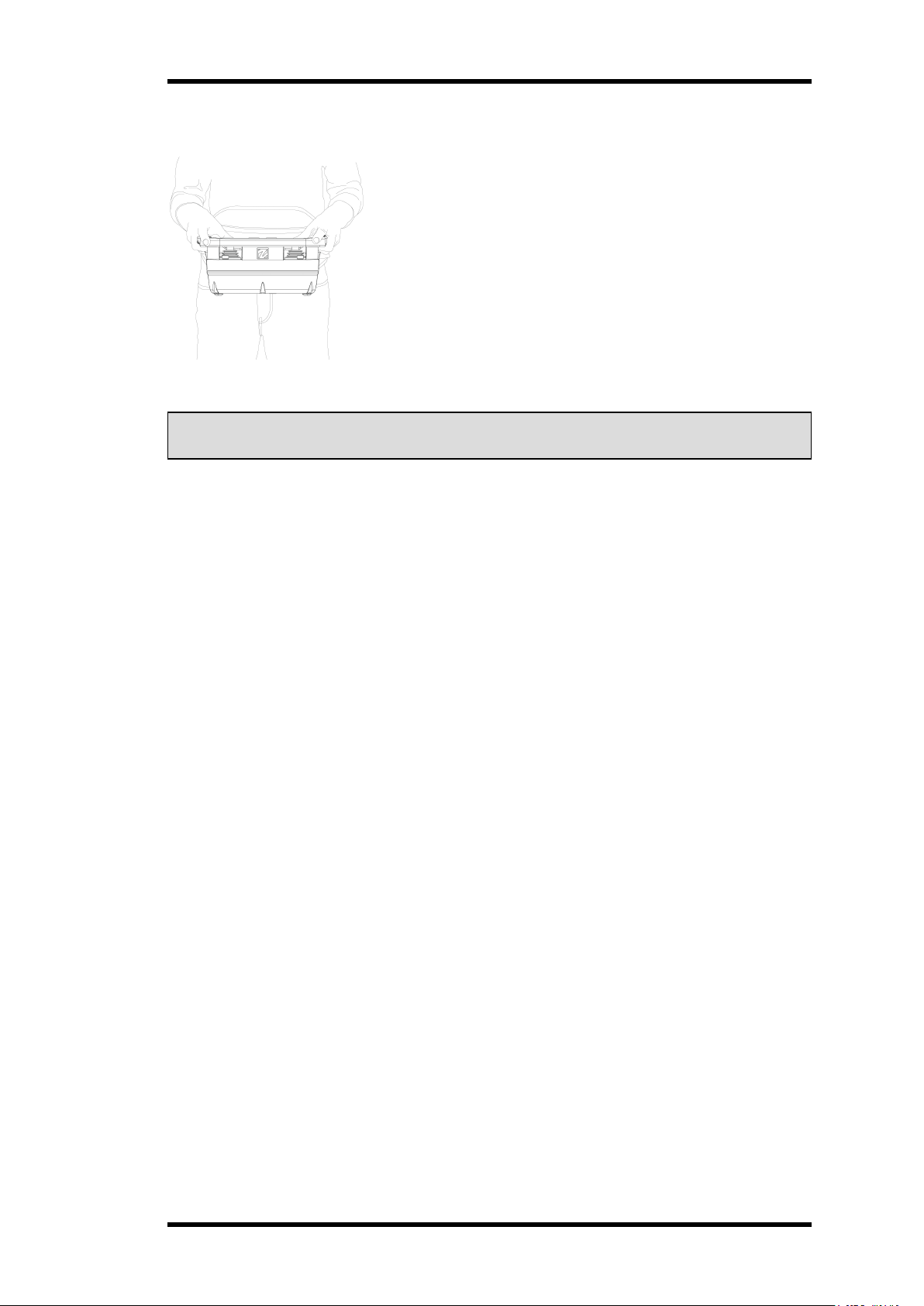
Ergonomics
Tele Radio AB transmitters are intended to be used together
with a Tele Radio AB waist belt or neck strap, for better
support and improved ergonomics while operating the
transmitter.
Adjust the belt around the waist, then hook the transmitter into
the waist belt straps.
Figure 1: Working position with a Tele Radio AB transmitter while using the Tele Radio AB waist
belt
NOTE! Always hold the transmitter with the control panel towards you. You must be able to read
any text on the control panel and understand the symbols on it.
Web Configuration Application
Transmitters can be customized using a Web Configuration App.
The Web Configuration App is a user-friendly tool for simple customization and configuration of
T24, T26, transmitters. It has an intuitive user interface and allows the trained technician to
perform all sorts of customization. e.g. design the faceplate, add expansion boards, define and
connect the I/O’s to the appropriate plug pin…
The Web Configuration App is a web-based tool accessible online for those with a customer
account. Contact your representative for more information.
All information on how to use the Web Configuration App can be found in the application itself or
in the corresponding documentation (PinConfig).
- 6 -

ABOUT THIS DOCUMENT
Before installing or operating the product, read the corresponding documentation carefully.
Tele Radio AB's product range is composed of transmitters and receivers intended for use
together as a system.
T26 systems are mainly intended for the hydraulic and mobile equipment markets. These
systems are not standardized but customized and adapted to each customer's needs. The
installation instructions cover general safety issues, main technical specifications, standard
installation, configuration and operating instructions, general troubleshooting and battery
information.
Images shown in this document may therefore not show the exact position of buttons, paddles
and are for illustrative purposes only.
How the outputs are connected to control the object depends on each specific installation and will
not be covered in this document. For exact details, see the technical documentation provided for
your specific system. Drawings, schematics and connection diagrams are unique and are also
provided together with the system.
Copyright
Information in this document is subject to change without notice. No part of this publication may
be reproduced, stored in a retrieval system, or transmitted in any form or by any means,
electronic, photographic, mechanical (including photocopying), recording or otherwise for any
purpose other than the purchaser's personal use without the written permission of Tele Radio AB.
Term and symbol definitions
The capitalized terms and symbol used herein shall have the following meaning:
l WARNING: indicates a hazardous situation which, if not avoided, could result in death or
serious injury.
l CAUTION: indicates a hazardous situation which, if not avoided, will result in minor or
moderate injury.
l IMPORTANT: is used for information that requires special consideration.
l NOTE: is used to address practices not related to physical injury.
This symbol is used to call attention to safety messages that would be assigned the
signal words "WARNING" or "CAUTION".
- 7 -
CHAPTER 2: SAFETY
l Tele Radio AB remote controls are often built into wider applications. These
systems should be equipped with:
l a wired emergency stop where necessary
l a brake
l an audible or visual warning signal
l Always switch off all electrical power from the equipment before installation
procedure.
l Only licensed or qualified personnel should be permitted to install the product.
l To utilize the safety features of the system, use the stop relays in the safety
circuitry of the object that you want to control.
l Avoid registering transmitters in receivers where they are not being used.
WARNINGS & RESTRICTIONS
Carefully read through the following safety instructions before proceeding
with the installation, configuration, operation, or maintenance of the product.
Failure to follow these warnings could result in death or serious injury.
This product must not be operated without having read and understood the Installation
instructions, the specific technical documentation (when provided), and having received the
appropriate training. The purchaser of this product has been instructed how to handle the system
safely. The following information is intended for use as a complement to applicable local
regulations and standards.
Installation and commission
This radio system must not be used in areas where there is a risk of
explosion.
- 8 -
Operation
l Only qualified personnel should be permitted to access the transmitter and
operate the equipment.
l Make sure that the user satisfies the age requirements in your country for
operating the equipment.
l Make sure that the user is not under the influence of drugs, alcohol and
medications.
l Make sure that the user knows and follows operating and maintenance
instructions as well as all applicable safety procedures and requirements.
l The user should:
l always test the transmitter stop button before operating it. This test
should be done on each shift, without a load. See "Stop button" on the
facing page.
l never use a transmitter if the stop button is mechanically damaged.
Contact your supervisor or representative for service immediately.
l never leave the transmitter unattended.
l always switch the transmitter off when not in use. Store in a safe place
l keep a clear view of the work area at all times.
l always remove all electrical power from the equipment.
l always follow lockout procedures.
Maintenance
l Keep the safety instructions for future reference. Always download the Installation
instructions from our website for the latest available version.
l Always contact your representative for service and maintenance work on the product.
l If error messages are shown, it is very important to find out what caused them. Contact
your representative for help.
l The functionality of the stop button should be tested at least after every 200 hours’ use
(see "Stop button" on the facing page).
l If the stop button is mechanically damaged, do not use the transmitter. Contact your
representative for service immediately.
Before maintenance intervention on any remote controlled equipments:
- 9 -
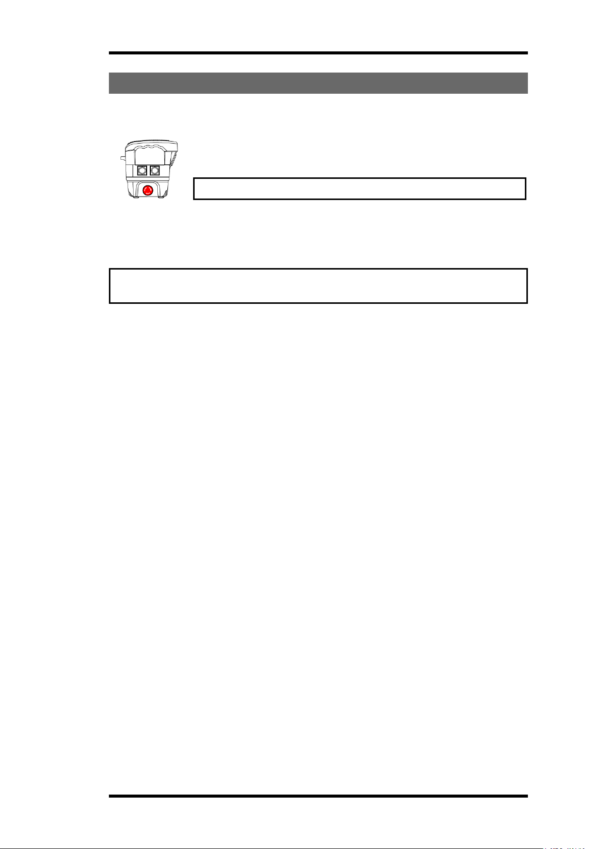
SAFETY FEATURES
Stop button
When the stop button is pressed, the safety relays on the receiver deactivate,
unless otherwise stated in the corresponding technical documentation
provided with each customized system.
IMPORTANT! Always use the stop button in an emergency.
T26
Figure 2: Example of possible locations for the stop button. Here on the right side of a T24 and
T26 transmitter.
IMPORTANT! The stop button should always be tested before operating the transmitter.
This test should be done on each shift, without a load.
To test the stop button:
1. Press the stop button.
2. Twist and release the stop button.
Safety relays (stop function)
Safety relays are designed to monitor the E-STOP functions and quickly interrupt the power to all
the relays in the receiver when the stop button is pressed.
R20 and R21 receivers are equipped with 2 stop relays controlled by the stop button on the
transmitter unit. Each safety relay is monitored and controlled by a dedicated micro-controller.
- 10 -
CHAPTER 3: TECHNICAL DATA
NOTE! The information below may differ in customized systems, please refer to the
corresponding technical documentation provided with each system.
SYSTEM SPECIFICATIONS
Radio frequency band 2405 – 2480 MHz
Frequency management Direct Sequence Spread Spectrum (DSSS)
Field Strength Adaptation Feature
Number of Channels 16 (11–26)
Range (typical) 100 m (328 ft), adjustable depending on configuration
System address 32 bit – 4 294 967 295 possibilities
Data format 250 kbit/s
Hamming distance 6
Operating temperature -20…+70 °C (-4…+158 °F)
Storage temperature -30…+80 °C (-22…+176 °F)
Safety standards IEC 61508 SIL 3, ISO EN 13849-1, CAT3 PLe
Pairing (registration) Easy to pair without tools and without opening the receiver
housing.
Bluetooth Bluetooth connectivity for configuration & settings via the Web and
mobile App.
Configuration Web and mobile App for Android & iOS
Settings Manager, PC configuration tool
TRANSMITTER SPECIFICATIONS
General specifications
IP code IP65 (Better Nema 4)
Power supply One (1) replaceable, rechargeable lithium-ion battery
Battery pack 3.7 V / 1600 mAh Li-ion – 1 battery compartment
Current consumption From 120 mA (depending on the configuration)
Operating time Up to 8 h (depending on the configuration)
HF Power < 13 dBm ~20 mW
Antenna Internal (external in option)
Functions Up to 40 analog functions
Up to 96 digital functions
Safety IEC 61508 SIL 3, ISO EN 13849-1, CAT3 PLe
Active & redundant E-Stop
Redundant joystick and switch functions
- 11 -
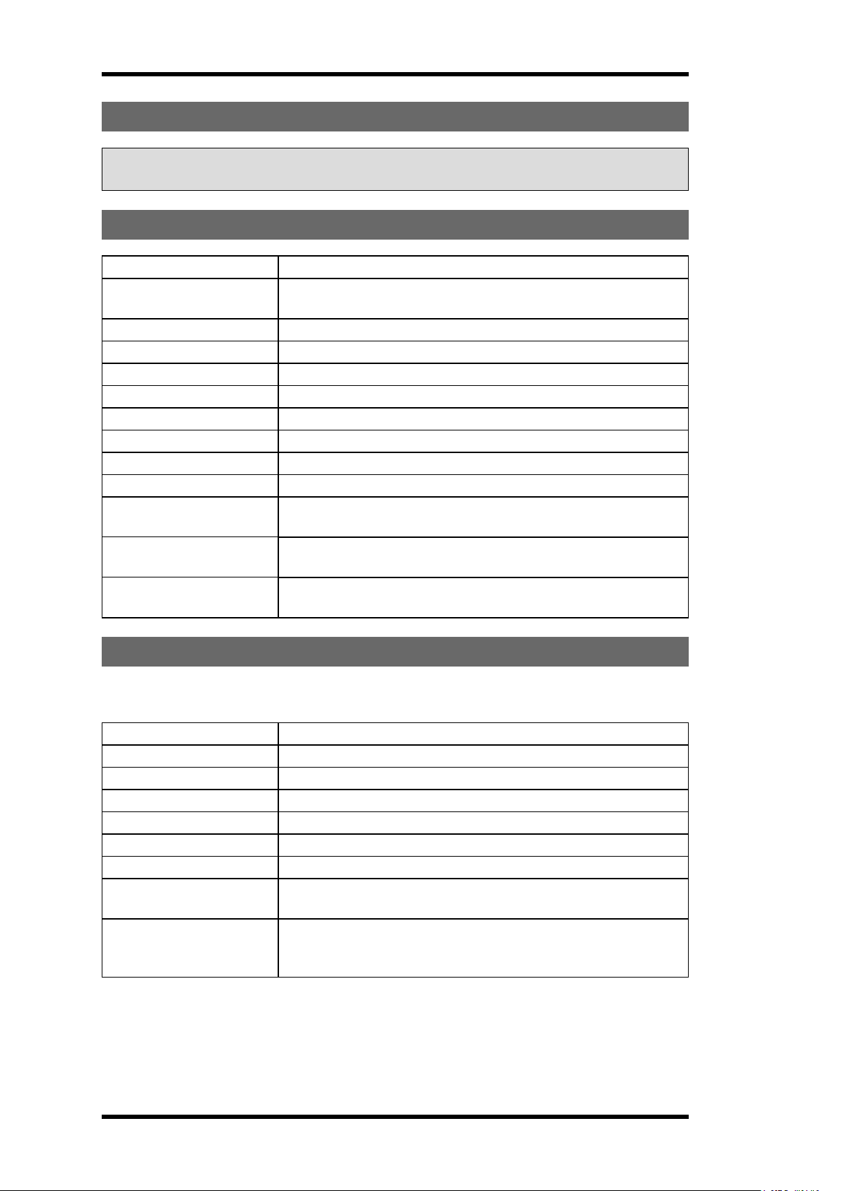
Other specifications
T26
T26-01 T26-06 T26-07 T26-81 T26-82
Number of joysticks * * * 2, 2-axis with spring return
for analogue control
directions (see "Joystick
directions" below).
Number of paddles * * * –
Number of switches * * * 3, toggle switch (On)–
None–(On) (spring return)
Stop button On the side No predefined position On the side
Key switch Yes No No Yes No
Display LCD 45 x 35 mm (1.77 x 1.37 inches)
Graphic / pixels with backlight sensor
Standard and Custom configurations
LED illuminated faceplate Yes No Yes Yes Yes
RFID Yes No No Yes Yes
Capacitive sensors in
handlebar (Operator
presence control )
Vibration motor for Haptic
feedback
Built-in impact, drop and tilt
protection
Cable backup In option Yes
Weight (typical) ~0.95 kg (~2.1 lbs) ~2 kg (~4.4 lbs)
Yes No Yes Yes Yes
Yes
Yes
*Depending on the configuration
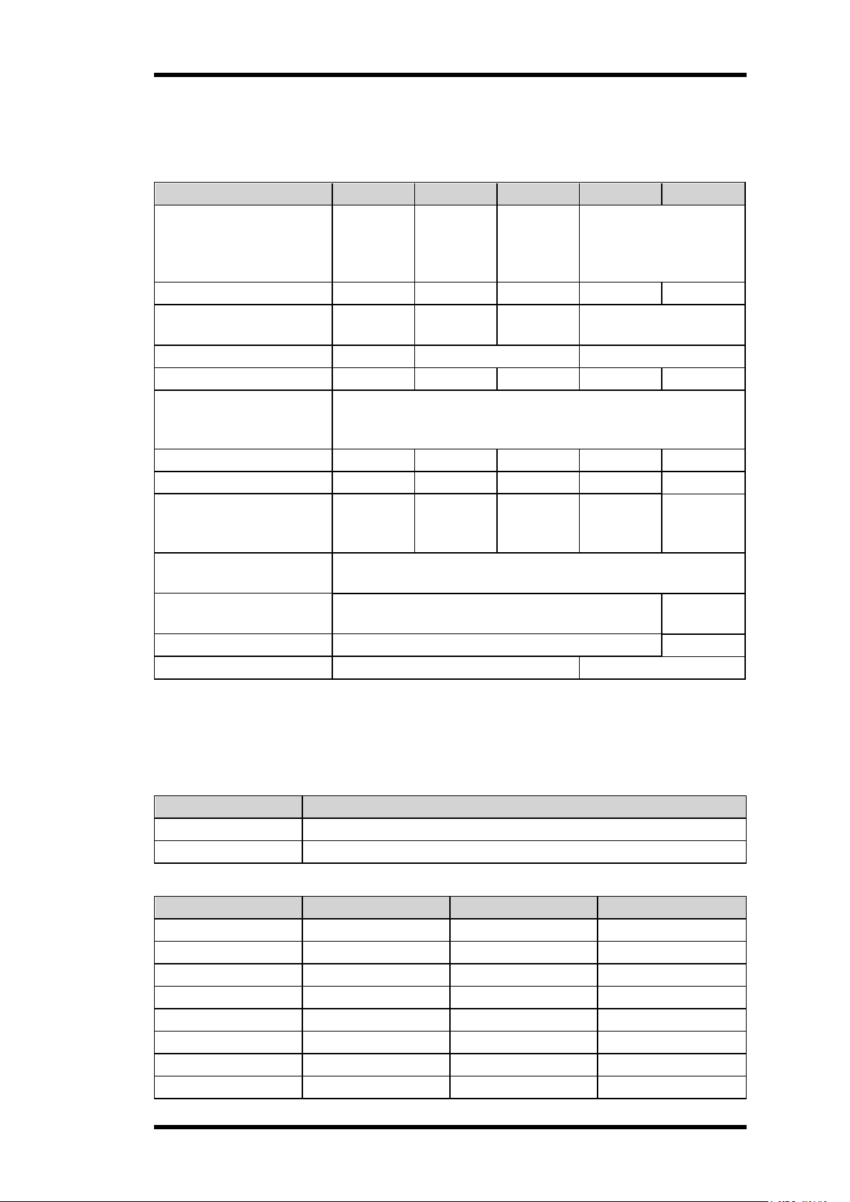
Joystick directions
The T26-81 and T26-82 transmitters have two joysticks (2-axis with spring-to-centre) allowing a
stepless control.
T26-81, T26-82
Joystick 1 (XY) Analog XY
Joystick 2 (XY) Analog XY
Code (XY) Movement control on X Movement control on Y Movement control on Z
0x2 – 2-step –
2x2 2-step 2-step –
2x0 2-step – –
4x4 4-step 4-step –
4x0 4-step – –
Analog XY stepless stepless –
Analog Y – stepless –
Analog XYZ stepless stepless stepless
- 12 -
Example:
Analog XY Analog Y
The joystick operates on both X and Y axes
with stepless movement from the center.
The joystick/paddle operates on the Y axe only
with stepless movement from center and back.
T27
T27-01
Number of joysticks *
Number of paddles *
Number of switches *
Stop button On the side
Key switch No
Display No
LED illuminated faceplate No
RFID No
Capacitive sensors in handlebar (Operator presence control ) No
Vibration motor for Haptic feedback No
Built-in impact, drop and tilt protection Yes
Cable backup No
Weight (typical) ~0.95 kg (~2.1 lbs)
*Depending on the configuration
- 13 -
CHAPTER 4: PRODUCT GENERAL DESCRIPTION
NOTE! The pictures shown in this chapter are for illustrative purposes only. Depending on the
configuration, the actual product appearance may differ from the basic model used for reference.
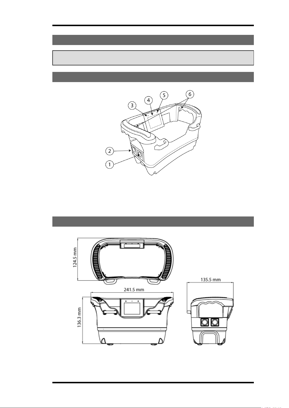
TRANSMITTER CASING
1. Side button 2
2. Side button 1
3. Status LED
* except T26-6.
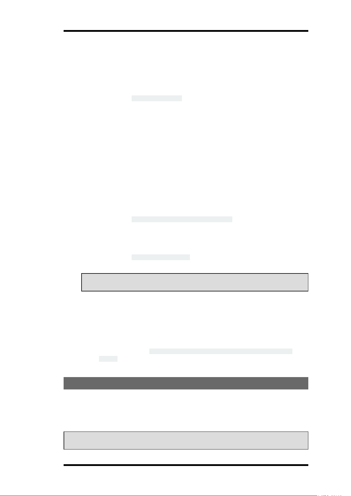
TRANSMITTER DIMENSIONS
4. LCD Display
5. Battery LED
6. Faceplate illumination LEDs*
- 14 -

T26-01
Transmitter top view
1. Handlebars
1
2. Status LED
Transmitter side views
Left side Right side
1. Side button 1
2. LCD display
4. Side button 2
5. Belt loops
3. LCD display
4. Battery LED
5. Customizable area
6. Belt loops
7. Side button 3 (start button)
8. Stop button
2
3. Handlebars
6. Side button 4 (start button)
9. Key switch
NOTE! By default, the on/off control of the faceplate LEDs is set to the side button 3.
1
With integrated faceplate illumination LEDs and capacitive sensors for Operator Presence Control.
2
Paddles, joysticks, buttons, etcs. depending on the configuration.
- 15 -

T26-06
Transmitter top view
1. Handlebars
2. Status LED
Transmitter side views
Left side Right side
1. Side button 1
2. LCD display
3. Handlebars
4. Side button 2
5. Belt loops
6. Side button 4 (start button)
3. LCD display
4. Battery LED
5. Customizable area
6. Belt loops
7. Side button 3 (start button)
8. Customizable area (e.g. for the
stop button)
9. Customizable area (e.g. for a key
switch)
1
1
Paddles, joysticks, buttons, etcs. depending on the configuration.
- 16 -

T26-07
Transmitter top view
1. Handlebars
1
2. Status LED
Transmitter side views
Left side Right side
1. Side button 1
2. LCD display
3. Handlebars
4. Side button 2
5. Belt loops
6. Side button 4 (start button)
7. Side button 3 (start button)
3. LCD display
4. Battery LED
5. Customizable area
2
6. Belt loops
8. Customizable area (e.g. for the
stop button)
9. Customizable area (e.g. for a key
switch)
NOTE! By default, the on/off control of the faceplate LEDs is set to the side button 3.
1
With integrated faceplate illumination LEDs and capacitive sensors for Operator Presence Control.
2
Paddles, joysticks, buttons, etcs. depending on the configuration.
- 17 -

T26-81
Transmitter top view
1. Handlebars
2. Status LED
3. LCD display
1
Transmitter side views
Left side Right side
1. Side button 1
5. Toggle switches 1–3
4. Battery LED
5. Joysticks 1–2
6. Belt loops
7. Toggle switches 1–3
8. Stop button
2. LCD display
3. Handlebars
4. Joysticks1–2
NOTE! By default, the on/off control of the faceplate LEDs is set to the side button 3.
1
With integrated faceplate illumination LEDs and capacitive sensors for Operator Presence Control.
6. Belt loops
7. Side button 3 (start button)
- 18 -
9. Side button 4 (start button)
10. Side button 2
11. Key switch

T26-82
Transmitter top view
1. Handlebars
2. Status LED
3. LCD display
Transmitter side views
Left side Right side
1. Side button 1
5. Toggle switches 1–3
4. Battery LED
5. Joysticks1–2
6. Belt loops
7. Toggle switches 1–3
8. Stop button
2. LCD display
3. Handlebars
4. Joysticks1–2
NOTE! By default, the on/off control of the faceplate LEDs is set to the side button 3.
1
With integrated faceplate illumination LEDs and capacitive sensors for Operator Presence Control.
1
6. Belt loops
7. Side button 3 (start button)
- 19 -
9. Side button 4 (start button)
10. Side button 2

T26 BOTTOM VIEWS
T26-01, T26-81
1. Key switch
2. Belt loops
3. Battery compartment
4. Stop button
T26-06, T26-07
5. Product label
6. RFID antenna (in option)
7. Replaceable battery
1. Customizable area (e.g. for a key switch)
2. Belt loops
3. Battery compartment
4. Customizable area (e.g. for the stop
button)
- 20 -
5. Product label
6. RFID antenna (in option)
7. Replaceable battery

T26-82
1. Customizable area (e.g. for a key switch)
2. Belt loops
3. Battery compartment
4. Stop button
T27-01
Transmitter top view
5. Product label
6. RFID antenna (in option)
7. Replaceable battery
1. Handlebars
2. Status LED
1
Paddles, joysticks, buttons, etcs. depending on the configuration.
3. Battery LED
4. Customizable area
- 21 -
5. Belt loops
1

Transmitter side views
Left side Right side
1. Side button 1
3. Side button 2
5. Side button 3 (start button)
2. Handlebars
4. Side button 4 (start button)
Transmitter bottom view
6. Stop button
7. Belt loops
1. Belt loops
2. Battery compartment
3. Stop button
4. Product label
5. RFID antenna (not implemented)
6. Replaceable battery
- 22 -

LEDS AND DISPLAY
The transmitters are equipped with 2 LEDs providing information about battery level, radio link
status and other status (see the LEDs status and error codes in the table below).
The transmitter display is intended for receiving and visualizing feedback information from the
system as well as for basic configuration. The T26 transmitter display is controlled by the
transmitter's side buttons.
1. Status LED
2. Battery LED
LEDs and display on the T26 transmitter
LED indicators
The transmitter has 2 bi-color LEDs for status indication:
l Battery LED is for battery indication.
Green means that the battery level is good while red indicates that the battery level is low.
When the battery LED turns red, the battery should be changed / recharged at the next
convenient opportunity.
l Status LED is for radio link and system information.
Status and error indications
Display LEDs status and error codes
LED Colour On Off Flash Indicates
Battery LED green X Battery level is good.
red X Battery level is low, must be charged.
red X Battery is charging and is not yet fully
charged.
– X No battery present in battery compartment.
Status LED green X When started, radio link ok.
green X When started, radio link not ok.
red X Fatal error. More information can be found on
the display.
red X Sending stop/ logout command. More
information can be found on the display.
- 23 -

CHAPTER 5: OPERATION (T26)
GENERAL INFORMATION
To control a receiver, the transmitter must be registered and logged in to the receiver. If another
transmitter is already logged in to the receiver, it must be logged out before a different transmitter
can be logged in.
If no transmitter is logged in to the receiver, proceed with the login procedure before using the
system. Once a transmitter has been logged in, it will remain logged in until it is manually logged
out.
More than one transmitter can be registered in the receiver, but only one transmitter can be logged
in at a time.
GENERAL NAVIGATION
By default, the Menu system is controlled by the transmitter's four side buttons.
1. Select button
2. Back button
3. Up button
4. Down button
Main menu
Button Action
1 (Select) Enter the selected menu
2 (Back) Back / cancel
3 and 4 (Up/Down) Move between the menu items
Enter numbers/ change a value
Button Action
1 (Select) Accept the updated value.
2 (Back) Cancel and go back to the menu without confirmation
3 and 4 (Up/Down) Increase/decrease the value displayed
Select a location in the menu
Button Action
1 (Select) Select/deselect the current location. Selected elements are indicated by
a + sign on the left of the selection.
2 (Back) Accept currently selected slots.
3 and 4 (Up/Down) Move through the location list.
- 24 -

START-UP PROTECTION
RFID tags can be activated to prevent unauthorized personnel from operating the transmitter. To
activate the RFID functions, contact your representative for assistance.
Once the RFID start-up protection functions have been activated, RFID tags need to be
registered in the transmitter before they can be used.
If the RFID start-up protection functions have been activated but no RFID tag has been
registered, this will be indicated on the display with the following warning message: [There are no
RFID stored in the settings. Register tags in the config menu.]
Once RFID tags have been registered, the display will show: [Waiting for a valid tag to be
presented…] each time the transmitter is started.
To register a RFID tag, see "Register RFID tags" on page 36.
FUNCTIONALITY TEST
NOTE! This list is intended for use as a support for the manufacturer of the equipment where
Tele Radio AB remote control systems are installed.
Before operating the radio system, follow the procedure below.
IMPORTANT! This test should be performed at each shift, without a load, and should
include but not be limited to the following steps
l Make sure that the controlled object can not cause any harm in the event of unexpected
movement.
l Always follow local safety rules and start the equipment according to the corresponding
instructions.
l Make sure that the transmitter can control the receiver by testing all functions.
l Make sure that the functions respond as expected.
l Make sure that all movements are as planned.
l Make sure that the stop button works correctly.
l Make sure that the stop function works correctly.
l Make sure the system stops when both batteries are removed from the transmitter.
- 25 -

LOG THE TRANSMITTER IN TO A RECEIVER
1. Make sure that the stop button is pressed.
2. Turn the key switch to the On position (horizontal).
3. Twist and release the stop button.
The initial start-up logo is displayed. Battery indicator(s) light(s).
The display shows: [Session Selection]
NOTE! Should the display show a warning message on zero position for the control
switch or joystick, release the affected controls in order to proceed. If the controls are not
released, the transmitter will block the corresponding inputs and display the following
warning message: [Inputs have been blocked. IO board 0X: 0xXXXXXXXX].
Enter the configuration menu and clear the locked inputs before proceeding with the login
procedure (see "Clear blocked inputs" on page 33).
3. Press the Select button to select one or more receiver(s) for the session.
The display shows: [Select one or more items] and the list of the registered receivers.
Selected receivers are marked with a + sign.
Select/change one or more receiver(s) Keep selected receiver(s)
4. Choose a receiver in the list using the
Up/Down buttons.
5. Press the Select button to select.
A + sign is displayed in front of the
selected receiver.
4. Press the Back button.
The display returns to the start screen:
[PUSH START BUTTONS]
6. Repeat steps 4–5 if necessary.
7. Press the Back button to accept.
The display returns to the start screen:
[PUSH START BUTTONS]
8. Press both Start buttons to start the
session.
The buzzer emits a beep. The display
shows:[Logging in…].
9. Push the stop button to exit the session.
The display shows: [Ending session…]
The login settings are now stored/ saved
in the transmitter.
START A SESSION
To be able to control a receiver using the transmitter, the transmitter must be registered and
logged in to a receiver.
When not in use, transmitters must be switched off and stored in a secure
storage space.
- 26 -

Do not use the system if the stop button is damaged or if it does not stop the
equipment. Doing so could result in serious injury or death.
NOTE! If the transmitter has never been logged in to the receiver before, the start-up procedure
will fail and the transmitter will turn off.
Start the transmitter again and log in to a receiver before proceeding with the start-up procedure
(see "Log the transmitter in to a receiver" on the previous page).
NOTE! The last accessed receiver(s) will automatically be selected the next time the transmitter
is started.
1. Make sure that all safety measures have been followed.
2. Make sure the transmitter battery is charged.
3. Make sure that the stop button is pressed.
4. Turn the key switch to the 'On' position (horizontal).
5. Twist and release the stop button.
The initial start-up logo is displayed. Battery indicator(s) light(s). The display shows:
[PUSH START BUTTONS]
NOTE! If the display shows a warning message on zero position for the control switch or
joystick, release the affected controls in order to proceed. If the controls are not released,
the transmitter will block the corresponding outputs and display the following warning
message: [Inputs have been blocked. IO board 0X: 0xXXXXXXXX].
Enter menu mode to clear the locked inputs before proceeding with the start-up procedure
(see "Clear blocked inputs" on page 33.
6. Press the Select button to check if there are receiver(s) selected for the session.
The display shows: [Select one or more items] and the list of registered receivers.
Selected receivers are marked with a + sign.
If the correct receiver is already selected
l Press the Back button.
The display returns to the start screen: [PUSH START BUTTONS]
l Proceed to step 11.
To select/change receiver(s):
l Proceed to next step.
7. Choose the receiver(s) to operate using the Up/Down buttons.
8. Press the Select button to select.
9. Repeat step(s) 7–8 if necessary.
10. Press the Back button to accept.
The display shows: [PUSH START BUTTONS]
11. Press and hold both start buttons simultaneously for one second.
The buzzer emits a beep.
12. Release both Start buttons.
The Status LED flashes rapidly while waiting for the receiver confirmation.
l If the transmitter has already been logged in to the receiver:
The display shows:[Logging in…]
The transmitter logs in to the receiver in which it has been registered.The Status
LED lights green.
- 27 -

l If the transmitter has not been logged in to the receiver:
The display shows:[Login failed. invalid set of RX's.] The transmitter turns off.
Start the transmitter again and log in to a receiver before proceeding with the startup procedure ("Log the transmitter in to a receiver" on page 26).
NOTE! If the paired receiver is not detected within 30 s, the login process is canceled and
the transmitter turns off.
13. Proceed with the functional test (see "Functionality test" on page 25).
LOG THE TRANSMITTER OUT FROM A RECEIVER
A transmitter already logged in to the receiver has to be logged out before any other transmitter
can be logged in.
NOTE! Logout can only be performed when the transmitter is on and a radio link with one or more
receivers has been established. The receiver must be powered-up for the logout procedure to be
successful.
NOTE! The logout procedure will log the transmitter out from all receivers that are part of the
radio session.
1. Press and hold both start buttons simultaneously.
2. Press the stop button
The display shows: [Logging out from session] and [Logout successful. Powering down]
3. Release both Start buttons.
The transmitter turns off.
SWITCH THE TRANSMITTER OFF
When the transmitter is active and the stop button is pressed, all relays on the receiver
deactivate.
NOTE! When the transmitter is switched off, it remains logged in to the receiver(s). To log out,
see "Log the transmitter out from a receiver" above
1. Press the stop button.
The display shows:[Ending session]
The transmitter turns off. All relays on the receiver deactivate.
- 28 -

CHAPTER 6: CONFIGURATION MENU (T26)
CONFIGURATION MENU AND STANDARD SETTINGS
The Configuration menu allows for certain settings to be set directly from the transmitter.
To access the configuration menu, turn on the transmitter, press the middle button on the right
side of the transmitter and keep it pressed while pushing the Stop button. Once in menu mode,
the following configuration menus will be available.
Menu Description
[Register
–
[Erase]
–
[Replace]
–
[Clear blocked input]
–
[Radio Channel]
–
[Backlight Intensity]
–
[Buzzer Volume]
–
[Radio Inactivity
–
Timeout]
[Startup protection –
–
RFID Learn]
[Startup protection –
–
RFID Erase]
[Repeater Configuration]
–
[Show device information]
–
[Show BLOB info]
–
[Start RFID Test]
–
Select a location to register a new receiver in. Radio
communication is immediately enabled when the registration
is confirmed.
Select a registered receiver to be erased from the transmitter.
Select a registered receiver to be replaced.
Reset any blocked input.
Select the channel/bank to use.
Set the display luminosity (in %).
Set the buzzer volume level (in %).
Set the off delay( in s) before the transmitter automatically
switches off.
Register one or more RFID tags in the transmitter for start up
protection.
Erase one or more registered RFID tag from the transmitter.
Add and set repeater(s).
Display the unit's serie number and a list of the software
versions currently installed on the transmitter.
Display BLOB information.
For testing the registered RFID tags.
Configuration menu protection
PIN codes can be activated to prevent unauthorized personnel from entering the Configuration
menu. To activate the PIN code functions, contact your representative for assistance. All PIN
code settings require assistance.
The Configuration menu can be protected by PIN codes with different access levels (ex: standard
and admin). Once the Configuration menu protection functions have been activated, a PIN code
will always be required for accessing the Configuration menu.
NOTE! Default PIN code for the standard access level is 1234.
- 29 -
Enter the Configuration menu (no PIN code required)
1. Make sure that the stop button is pressed.
2. Turn the key switch to the 'On' position (horizontal).
3. Twist and release the stop button.
The initial start-up logo is displayed. Battery indicator(s) light(s).
The display shows: [Session Selection]
4. Press and hold side button 3.
5. Press the stop button.
6. Release side button 3.
The display shows the menu list.
7. Select a menu by using the navigation and function buttons on the transmitter display (see
"General navigation" on page 24).
Enter the Configuration menu (PIN code required)
1. Make sure that the stop button is pressed.
2. Turn the key switch to the 'On' position (horizontal).
3. Twist and release the stop button.
The initial start-up logo is displayed. Battery indicator(s) light(s).
The display shows: [Ses[Session Selection]sion Selection]
4. Press and hold side button 3.
5. Press the stop button.
6. Release side button 3.
The display shows: [Config Menu PIN 0000]
7. Enter the first digit using the Up/Down buttons.
NOTE! Once the Select button has been pressed, it is not possible to move back to the
previous digit. Pressing the Back button will abort the procedure.
8. Press the Select button to accept and move to the next digit.
9. Repeat steps 7–8 until all four digits have been entered.
10. Press the Back button to accept.
l If the entered PIN code is correct:
The display returns to the menu list.
l If the entered PIN code is incorrect:
The display shows: [Config Menu PIN Incorrect PIN entered, shutting down
device]. The transmitter turns off.
Go back to step 1 and try again.
REGISTER A TRANSMITTER IN A RECEIVER
To control a receiver, the transmitter must be registered in the receiver, and logged in to the
receiver. More than one transmitter can be registered in the receiver, but only one transmitter can
be logged in at a time.
T26 transmitters can have up to 32 registered receivers (locations 1–32).
NOTE! The registration instructions require access to the receiver housing. For the registration
procedure to be successful, the receiver must be powered up.
- 30 -

Do not perform this action when the receiver is in a session with another
transmitter. The radio communication may be interrupted or broken.
On the Receiver On the Transmitter
1. Power the receiver up.
LED 1 is flashing (red). If Bluetooth has
been activated, the LED 5 will also flash
(blue).
2. Press and hold the cap sensor button
until LED1 stops flashing.
LEDs 2–5 flash (fast).
3. Release the cap sensor button.
LEDs 1–5 flash (slow).
The receiver is now in registration mode.
If no register command is received
within 30 seconds, the receiver will
exit registration mode.
1
4. Make sure that the stop button is
pressed.
5. Turn the key switch to the 'On' position
(horizontal).
6. Twist and release the stop button.
The initial start-up logo is displayed.
Battery indicator(s) light(s). The display
shows: [Session Selection].
7. Enter the Configuration menu (see
"Enter the Configuration menu (no PIN
code required)" on the previous page).
8. Navigate to the [Register] menu using
the Up/Down buttons.
9. Press the Select button to enter.
10. Choose a location for the receiver to be
registered in using the Up/Down
buttons.
11. Press the Select button to select.
A + sign is displayed in front of the
selected location.
12. Press the Back button to accept.
The display shows: [Registration in
progress…]
1
It is also possible to exit registration mode by briefly touching the receiver's cap sensor button.
- 31 -

When the transmitter's register command is received, …
On the Receiver On the Transmitter
LEDs 1–5 flash (fast). The display shows:[Confirm registration on
the receiver].
13. Press the Cap sensor button for at least
2 s.
The display shows:[Registration successful.
Transmitter was registered in HY-RX-xxxxx].
LEDs 1–5 flash three times.
The transmitter is now registered.
On the Receiver On the Transmitter
LED 1 is flashing (slow). The transmitter turns off.
If not successfully completed:
On the Receiver On the Transmitter
The receiver exits registration mode.
LED 1 is flashing (red). If Bluetooth has been
activated, the LED 5 will also flash (blue).
The display shows:[Registration failed
Timout]. The transmitter turns off.
Go back and proceed from step 2.
ERASE A TRANSMITTER FROM A RECEIVER
This procedure erases the transmitter from the receiver and vice versa.
NOTE! The receiver must be powered up for the Erase procedure to be successful.
1. Make sure that the stop button is pressed.
2. Twist and release the stop button.
The Initial start-up logo is displayed. Battery indicator(s) light(s). The display shows:
[Session Selection][PUSH START BUTTONS].
3. Enter the Configuration menu (see "Enter the Configuration menu (no PIN code required)"
on page 30)
4. Navigate to the [Erase] menu using the Up/Down buttons.
5. Press the Select button to enter.
6. Choose the receiver(s) to be erased from using the Up/Down buttons.
7. Press the Select button to select.
A + sign is displayed in front of the selected item(s).
8. Press the Back button to accept.
The display shows: [Erase in progress…]
l If successfully completed:
The display shows: [Erase successful]. The transmitter turns off.
l If not successfully completed:
The display shows: [Erase failed. Timout]. The transmitter turns off. Go back to
step 1 and try again.
- 32 -

CLEAR BLOCKED INPUTS
On start up, the T26 transmitters perform a zero position check for control switches, joysticks
and/or paddles.
If the transmitter detects that some control commands
are not in the zero position, the following warning
message is displayed:
If the affected controls are not released, the transmitter
will block the corresponding inputs and display the error
message:
The next time the transmitter is started, the display will
show the warning message:
[One or more inputs are not in the
zero/startup position]
[Release all controls to proceed.]
[Zero position problem
identification in progress.]
[Please wait for device to
automatically restart]
[Inputs have been blocked.]
[IO board 0X: 0xXXXXXXXX].
To clear the locked inputs:
1. Make sure that the stop button is pressed.
2. Turn the key switch to the 'On' position (horizontal).
3. Twist and release the stop button.
The initial start-up logo is displayed. Battery indicator(s) light(s). The display shows:
[Session Selection]
4. Enter the Configuration menu (see "Enter the Configuration menu (no PIN code required)"
on page 30).
5. Navigate to the [Clear blocked input] menu using the Up/Down buttons.
6. Press the Select button to enter.
The display shows: [Value: False]
7. Press the Up or Down button to change [False] to [True].
8. Press the Select button to confirm.
l If successfully completed:
The display shows: [Clear blocked input successful]. The display returns to the
menu list.
l If not successfully completed:
The display shows: [Clear blocked input failed Timout]. The transmitter turns off.
Go back to step 1 and try again.
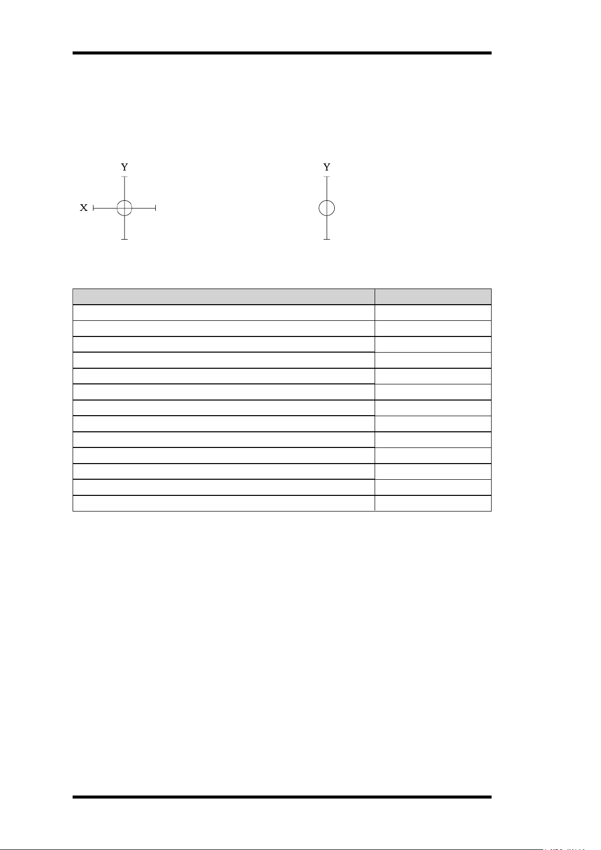
SELECT A RADIO FREQUENCY CHANNEL
To change radio channel:
1. Make sure that the stop button is pressed.
2. Turn the key switch to the 'On' position (horizontal).
3. Twist and release the stop button.
The initial start-up logo is displayed. Battery indicator(s) light(s).
The display shows: [Session Selection]
4. Enter the Configuration menu (see "Enter the Configuration menu (no PIN code required)"
on page 30).
5. Navigate to the [Radio Channel] menu using the Up/Down buttons.
- 33 -

6. Press the Select button to enter.
The display shows:
[Range: 11–26]
[Value: XX]
7. Change the channel number using the Up/Down buttons.
Channel number Frequency (MHz) Channel number Frequency (MHz)
11 2405 19 2445
12 2410 20 2450
13 2415 21 2455
14 2420 22 2460
15 2425 23 2465
16 2430 24 2470
17 2435 25 2475
18 2440 26 2480
SET THE BACKLIGHT INTENSITY
Set the LCD screen luminosity level (in %).
1. Make sure that the stop button is pressed.
2. Turn the key switch to the 'On' position (horizontal).
3. Twist and release the stop button.
The initial start-up logo is displayed. Battery indicator(s) light(s).
The display shows: [Session Selection]
4. Enter the Configuration menu (see "Enter the Configuration menu (no PIN code required)"
on page 30).
5. Navigate to the [Backlight Intensity] menu using the Up/Down buttons.
6. Press the Select button to enter.
The display shows:
[Range: 0–100]
[Value: XX]
7. Change the backlight intensity value using the Up/Down buttons.
8. Press the Select button to confirm.
The display returns to the menu list.
- 34 -

SET BUZZER VOLUME
Set the buzzer volume level (in %).
1. Make sure that the stop button is pressed.
2. Turn the key switch to the On position (horizontal).
3. Twist and release the stop button.
The initial start-up logo is displayed. Battery indicator(s) light(s).
The display shows:[Session Selection]
4. Enter the Configuration menu (see "Enter the Configuration menu (no PIN code required)"
on page 30).
5. Navigate to the [Buzzer Volume] menu using the Up/Down buttons.
6. Press the Select button to enter.
The display shows:
7. Change the buzzer volume value using the Up/Down buttons.
8. Press the Select button to confirm.
The display returns to the menu list.
[Range: 0–100]
[Value: XX]
SET THE RADIO INACTIVITY TIMEOUT
Set the off delay (in seconds) before the transmitter automatically turns off.
1. Make sure that the stop button is pressed.
2. Turn the key switch to the On position (horizontal).
3. Twist and release the stop button.
The initial start-up logo is displayed. Battery indicator(s) light(s).
The display shows: [Session Selection]
4. Enter the Configuration menu (see "Enter the Configuration menu (no PIN code required)"
on page 30).
5. Navigate to the [Radio Inactivity Timeout] menu using the Up/Down buttons.
6. Press the Select button to enter.
The display shows:
7. Change the off delay value using the Up/Down buttons.
8. Press the Select button to confirm.
The display returns to the menu list.
[Range: 0–255]
[Value: XX]
- 35 -

REGISTER RFID TAGS
NOTE! If the RFID functions are not activated, contact your representative for assistance.
To register a RFID tag:
1. Make sure that the stop button is pressed.
2. Turn the key switch to the On position (horizontal).
3. Twist and release the stop button.
The initial start-up logo is displayed. Battery indicator(s) light(s).
The display shows: [Session Selection]
4. Enter the Configuration menu (see "Enter the Configuration menu (no PIN code required)"
on page 30).
5. Navigate to the [Startup Protection – RFID Learn] menu using the Up/Down buttons.
6. Press the Select button to enter.
The display shows:[Select a single item] and the list showing the registered RFID tags'
ID numbers.
7. Choose a location for the RFID tag to be registered in using the Up/Down buttons.
8. Press the Select button to select.
A + sign is displayed in front of the selected location.
9. Press the Back button to accept.
The display shows: [Waiting for a valid tag to be presented…]
10. Turn the transmitter upside down and place the RFID tag against the RFID antenna.
l If successfully completed:
The buzzer emits 3 short beeps. The display returns to the menu list.
l If no tag is presented within 20 s:
The transmitter turns off.
The next time the transmitter is started, the display will shows: [Waiting for a
valid tag to be presented…]. Proceed with step 10 to complete the registration.
NOTE! To check that the RFID tag has been properly registered, repeat step 1 to 6.
ERASE RFID TAGS
NOTE! If the RFID functions are not activated, contact your representative for assistance.
To erase a RFID tag:
1. Make sure that the stop button is pressed.
2. Turn the key switch to the On position (horizontal).
3. Twist and release the stop button.
The initial start-up logo is displayed. Battery indicator(s) light(s).
The display shows: [Session Selection]
4. Enter the Configuration menu (see "Enter the Configuration menu (no PIN code required)"
on page 30).
5. Navigate to the [Startup Protection – RFID Erase] menu using the Up/Down buttons.
- 36 -

6. Press the Select button to enter.
The display shows: [Select a single item] and the list showing the registered RFID tags'
ID numbers.
7. Choose the RFID tag to be erased using the Up/Down buttons.
8. Press the Select button to select.
A + sign is displayed in front of the selected item.
9. Press the Back button to accept.
The display shows: [Confirmed]. The display returns to the menu list.
*To check that the RFID tag has been properly erased, see "Register RFID tags" on the previous
page, steps 1 to 6.
SHOW THE DEVICE INFORMATION
Display the transmitter's series number and CPU versions .
To see the transmitter's information:
1. Make sure that the stop button is pressed.
2. Turn the key switch to the On position (horizontal).
3. Twist and release the stop button.
The initial start-up logo is displayed. Battery indicator(s) light(s).
The display shows: [Session Selection]
4. Enter the Configuration menu (see "Enter the Configuration menu (no PIN code required)"
on page 30).
5. Navigate to the [Show device information] menu using the Up/Down buttons.
6. Press the Select button to enter.
The display shows:
[CPU01: XXXX]**
…
* S/N = serie number; HY= Tele Radio AB's internal product code; TX= transmitter
** CPU01–04: Id number of the software currently used in each of the transmitter's CPU cards.
[S/N: HY-TXXXX]*
- 37 -

CHAPTER 7: BATTERY
l Risk of explosion if battery is replaced with a battery of an incorrect type.
l Do not short circuit, disassemble, deform or heat batteries.
l Never attempt to charge a visibly damaged or frozen battery.
l Do not use or charge the battery if it appears to be leaking, deformed or damaged
in any way.
l Do not solder directly onto batteries.
l Do not leave the battery in the charger once it is fully charged.
l Store in a cool location. Keep batteries away from direct sunlight, high
temperature, and high humidity.
l Immediately discontinue use of the battery if, while using, charging, or storing the
battery, the battery emits an unusual smell, feels hot, changes color, changes
shape, or appears abnormal in any other way.
l Keep batteries out of reach of small children. Should a child swallow a battery,
consult a physician immediately.
l Do not place multiple batteries in the same plastic bag.
l Do not incinerate or dispose of batteries in fire.
l Do not place used batteries in the household waste. Dispose of used batteries in
accordance with the applicable regulations and legal requirements.
l Batteries that have been disposed of incorrectly may short circuit, causing them
to become hot, burst or ignite.
BATTERY PRECAUTIONS
Carefully read the following safety instructions and warnings before using, charging or
disposing of the batteries.
Batteries contain flammable substances such as lithium or other organic
solvents, which may result in overheating, rupture or combustion. Failure to
read and follow the below instructions may result in fire, personal injury and
damage to property if charged or used improperly
Handling and storage
Disposal
When discarding batteries, insulate the + and - terminals of batteries with insulating/ masking
tape.
- 38 -

BATTERY INFORMATION
NOTE! Only batteries approved by Tele Radio AB should be used in T26 transmitters.
T26 transmitters are equipped with one battery. Battery level is indicated by the LED indicator on
the transmitter's display (see "LED indicators" on page 23).
The battery can be recharged using a Tele Radio AB battery charger (e.g. table charger or car
cigarette lighter adapter) or the AC main charger adapter.
BATTERY PACK
Article number M245060
Battery type Replaceable, rechargeable lithium-ion battery
Weight (typical) 0.47 kg (1.04 lbs)
Voltage 3.7 V / 1600 mAh
Charging time ~ 4 h with an empty battery
Charging cycle 600 cycles
Charging temperature 0…+45 °C / +32…+113 °F
CHARGERS
Charger type Car cigarette lighter
Input/output power 12 – 24 V DC / 5 V DC 110 – 240 V AC /
Weight (typical) 0.11 kg (0.25 lbs) – 0.12 kg (0.26 lbs)
Dimensions – – 90 x 25 x 135 mm
Other – Supplied with multiple
1
M769746 M769780 M769755 + M769780
AC adapter Table charger
adapter
5 V DC, 10 % (1A)
5 V DC
(3.5 x 1 x 5.3 in)
Can be wall-mounted
connector types
NOTE! Electronics and batteries must be physically separated before disposal. Make sure that
electronics or batteries are not disposed of in household waste.
Charge the battery in the table charger
NOTE! When approximately 10 % of a battery capacity remains, the corresponding battery LED
will light red.
1. Remove the battery from its compartment and place it in the Tele Radio AB battery
charger.
2. The charger's LED lights red while the battery is charging.
3. The charger's LED turns green when the battery is fully charged.
4. Put the battery back into the transmitter's corresponding compartment.
AC adapter
The AC adapter can be used for charging the batteries while they are being used. It can also
power the transmitter while the batteries are removed and charged in the battery charger.
1
Must be purchased separately.
- 39 -

CHAPTER 8: WARRANTY, SERVICE, REPAIRS, AND MAINTENANCE
Tele Radio AB products are covered by a warranty against material, construction and
manufacturing faults. During the warranty period, Tele Radio AB may replace the product or faulty
parts. Work under warranty must be performed by Tele Radio AB or by an authorized service
center specified by Tele Radio AB.
The following are not covered by the warranty:
l Faults resulting from normal wear and tear
l Parts of a consumable nature
l Products that have been subject to unauthorized modifications
l Faults resulting from incorrect installation and use
l Damp and water damage
MAINTENANCE
l Repairs and maintenance must be performed by qualified personnel
l Only use spare parts from Tele Radio AB
l Contact your representative for service or any other assistance
l Keep the product in a clean, dry place
l Keep contacts and antennas clean
l Wipe off dust using a slightly damp, clean cloth
NOTE! Never use cleaning solutions or high-pressure washer.
- 40 -

CHAPTER 9: REGULATORY INFORMATION
EUROPE
Applies to:
T26, T26-01, T26-06, T26-07, T26-81, T26-82
T27, T27-01
CE marking
Hereby, Tele Radio AB, declares that the radio equipment type(s) listed above is/ are in
compliance with Directive 2014/53/EU.
The latest version of the complete EU Declaration of Conformity is available on the Tele Radio
AB website, www.tele-radio.com.
WEEE directive
This symbol means that inoperative electrical and electronic products must not be
mixed with household waste. The European Union has implemented a collection and
recycling system for which producers are responsible. For proper treatment, recovery
and recycling, please take this product to a designated collection point.
Tele Radio AB strives to minimize the use of hazardous materials, promotes reuse and recycling,
and reduces emissions to air, soil and water. When a commercially viable alternative is available,
Tele Radio AB strives to restrict or eliminate substances and materials that pose an
environmental, health or safety risk.
NORTH AMERICA
Applies to:
T26, T26-01, T26-06, T26-07, T26-81, T26-82
T27, T27-01
FCC statement
This device complies with part 15 of the FCC Rules. Operation is subject to the following two
conditions:
(1) This device may not cause harmful interference, and
(2) this device must accept any interference received, including interference that may cause
undesired operation.
Changes or modifications not expressly approved by the party responsible for compliance could
void the user’s authority to operate the equipment.
This equipment has been tested and found to comply with the limits for a Class B digital device,
pursuant to part 15 of the FCC Rules. These limits are designed to provide reasonable protection
against harmful interference in a residential installation. This equipment generates uses and can
radiate radio frequency energy and, if not installed and used in accordance with the instructions,
may cause harmful interference to radio communications. However there is no guarantee that
interference will not occur in a particular installation. If this equipment does cause harmful
interference to radio or television reception, which can be determined by turning the equipment off
- 41 -

and on, the user is encouraged to try to correct the interference by one or more of the following
measures:
l Reorient or relocate the receiving antenna.
l Increase the separation between the equipment and receiver.
l Connect the equipment into an outlet on a circuit different from that to which the receiver is
connected.
l Consult the dealer or an experienced radio/TV technician for help.
To satisfy FCC RF exposure requirements, a separation distance of 20 cm or more should be
maintained between the antenna of this device and persons during device operation. To ensure
compliance, operations at closer than this distance is not recommended.
IC Statement
This product complies with Industry Canada's licence-exempt RSSs. Operation is subject to the
following two conditions:
(1) This device may not cause interference; and
(2) This device must accept any interference, including interference that may cause undesired
operation of device.
Le présent appareil est conforme aux CNR d’Industrie Canada applicables aux appareils radio
exempts de licence. L’exploitation est autorisée aux deux conditions suivantes :
1) l’appareil ne doit pas produire de brouillage;
2) l’appareil doit accepter tout brouillage radioélectrique subi, même si le brouillage est
susceptible d’en compromettre le fonctionnement.
To satisfy IC RF exposure requirements, a separation distance of 20 cm or more should be
maintained between the antenna of this device and persons during device operation. To ensure
compliance, operation at closer than this distance is not recommended.
Afin d'assurer la conformité aux exigences de la IC en matière d'exposition aux RF, une distance
de séparation d'au moins 20 cm doit être maintenue entre l'antenne de cet appareil et toute
personne à proximité pendant le fonctionnement de l'appareil. Pour assurer le respect de ces
exigences, il n'est pas recommandé d'utiliser l'appareil à une distance inférieure à celle-ci.
FCC/IC labels
The radio module in this product is labeled with its own FCC ID and IC numbers. The FCC ID and
IC numbers are not visible when the radio module is installed inside another device. Therefore,
the outside of the device into which the module is installed must also display a label referring to
the enclosed radio module. The final end device must be labeled in a visible area with the
following:
“Contains …
“Contains …
The FCC and IC numbers are found on the product label.
RADIO MODULE
The products described in these instructions contain the radio modules:
PRODUCT RADIO MODULE
T26 D00005-15
- 42 -

This page intentionally left blank.
- 43 -
These installation instructions are subject to change without prior notice.
Download the latest installation instructions from www.tele-radio.com.
 Loading...