

Tele Radio Panther
SAFETY INSTRUCTIONS
1 2
1
2
3
4
5
6
7
8
Standard settings
LANGUAGE: ENGLISH (ORIGINAL)
CE-IM-PN-RX002-A01-EN
ARTICLE CODE: PN-R8-1, PN-T7-2

Thank you for purchasing a Tele Radio product
2150
PN-R8-1, PN-T7-2
READ ALL INSTRUCTIONS CAREFULLY BEFORE MOUNTING, INSTALLING AND
CONFIGURATING THE PRODUCT.
These instructions are published by Tele Radio AB without any guarantee. These
instructions are solely directed towards qualied installers. The instructions may be
removed or revised by Tele radio AB at any time and without any further notice.
Corrections and additions will be added to the updated versions of the instructions.
The instructions that contain information on the installation and conguration of the
remote radio control unit on the machine are not intended to be passed on to the end
user. Only such information may be passed on to the end user, that is needed to operate
the machine correctly by radio remote control.
Tele Radio AB products are covered by a guarantee against material, construction or
manufacturing faults. During the guarantee period, Tele Radio AB may replace the product
or faulty parts with new. Work under guarantee must be carried out by Tele Radio AB
or by an authorized service centre specied by Tele Radio AB. Make sure that repairs and
maintenance are only carried out by qualied personnel. Use only spare parts from Tele
Radio AB. Contact your Tele Radio representative if you need service or support. The EC
declaration of conformity can be downloaded from our website.
©Tele Radio AB, 2011
TELE RADIO AB
Datavägen 21, SE-436 32 Askim. Sweden
Tel: +46-31-748 54 60
Fax: +46-31-68 54 64
www.tele-radio.com
TECHNICAL DATA RECEIVER
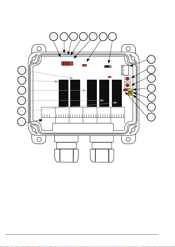
R8-1 (BASE BOARD)
10
9
7
8
LEDs
5 1 2 3 4
11
12
LED6
1
2
3
Relay 5 Relay 1 Relay 3Relay 2 Relay 4
4
5
6
1
+ -
12-24 V DC
2
3456789
CO NO NC
CO NO NC
1 (on/off)
WR/5
10111213141516
CO NO NC 2CO NO NC
3 (kill)
13
CO NO NC
4 (Buzzer)
18
19
20
F
S
LED8
LED7
LED9
LED10
15
16
17
18
19
14
17
20
1. Relay 1- on/off relay
2. Relay 5- work relay
3. Relay 2
4. Relay 3- kill relay
5. Relay 4- buzzer relay
6. Power supply connection
6-30 V DC
7. Relay LED 5
8. Relay LED 1
9. Relay LED 2
10. Relay LED 3
11. Relay LED 4
4
12. Power supply LED 6
13. Trabus programming connector
14. Terminal block for RS232
15. Function button (Cancel)
16. Select button (OK)
17. LED 8
18. LED 9
19. LED 10
20. LED 7
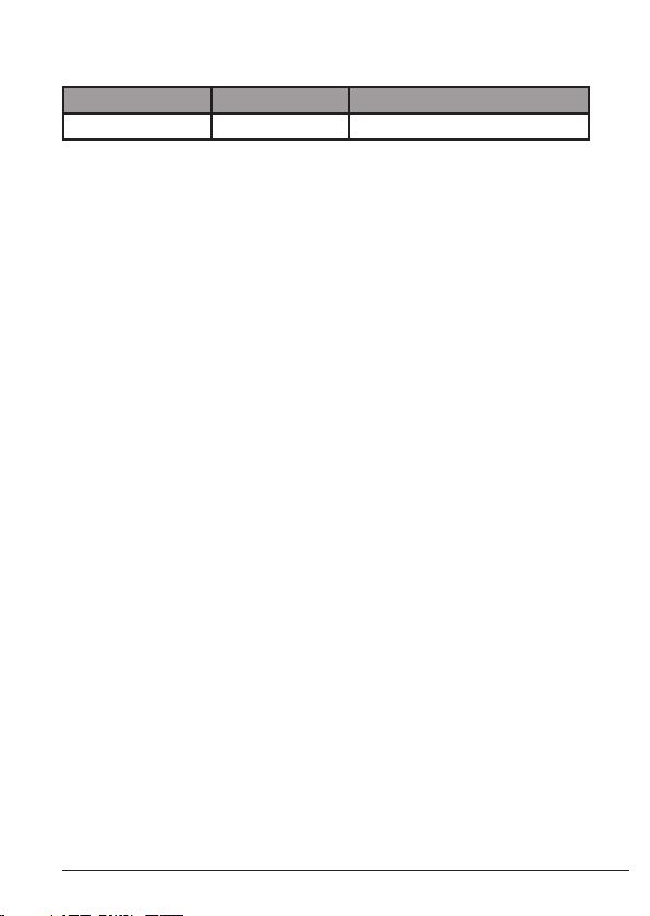
Current consumption
RECEIVER MODEL SUPPLY VOLTAGE MAX. CURRENT CONSUMPTION
R8-1 12-24 V DC <200 mA.
Technical data
FUNCTIONAL RELAYS: 5 potential free* functional relays
NO/NC 8A ACI
NUMBER OF CHANNELS: 16
SIZE: 120 x 116 x 50 mm./
4.7” x 4.6” x 2”
WEIGHT: 400 grams/ 14 oz.
IP CLASS: IP66
FREQUENCY: 2405-2480 MHz.
* Potential free means that you need to supply voltage to get power out of a relay (e.g. via a
connection comb).
SYSTEM APPLICATION AREA
The Panther system is a simplex radio communication system that is
preferentially aimed towards professional industry, e.g. radio controlling of
winches and mobile applications. The functionality of the Panther systems
is as varied and versatile as are the needs of our customers.
5

LED INDICATIONS
LED INDICATIONS DURING START UP
1. All receiver LEDs lit up for 0.5 sec. to show that they are working.
2. Current settings are shown for 2 sec.
On relay LEDs 1-4:
Relay LED 1 OFF Continuous transmitting mode
ON Discontinuous transmitting mode
Relay LED 2 OFF Custom ID not enabled
ON Custom ID enabled
Relay LED 3 OFF Conguration ID not enabled
ON Conguration ID enabled
Relay LED 4 OFF Frequency scan on
ON Frequency scan off (xed frequency)
On LED 7, 8 and 9:
LED 7 ON Operating mode 1 (direct mode)
LED 8 ON Operating mode 2 (lifting mode)
LED 9 ON Operating mode 3 (LML mode)
LED INDICATIONS IN PROGRAMMING MODE
LED 7 red ON
LED 8 yellow ON
LED 9 green ON
LED 10 orange ON
6

LED INDICATIONS DURING OPERATION
LED 6 red ON Power to the receiver is on
OFF Power to the receiver is off
LED 7 red OFF No transmitter registered
ashes (slow) At least one transmitter is
ashes (quick) At least one transmitter is registered,
ON Valid radio packages from a registered
registered and one transmitter is
logged in, but not transmitting.
but not transmitting.
transmitter received.
ERROR INDICATIONS ON LEDS
LED 7
(red)
LED 7
(red)
+ LED 8
(yellow)
ON Reading of production data failed.
Contact your representative.
ON Radio module startup failed. Contact
your representative.
LED 8 ON A radio package not coming from a
LED 8 + LED 9 ON A radio package from a transmitter in a
LED 8 + LED 10 ON A radio package is received from a
LED 9 ON A radio package is received, but the
LED
10
Panther transmitter is received.
different mode (discontinuous or
continuous) than the receiver is
received.
transmitter that is not registered.
radio signal strength (RSSI) is too low.
ON A radio package is received, but the
conguration ID is not accepted.
7
TECHNICAL DATA TRANSMITTER
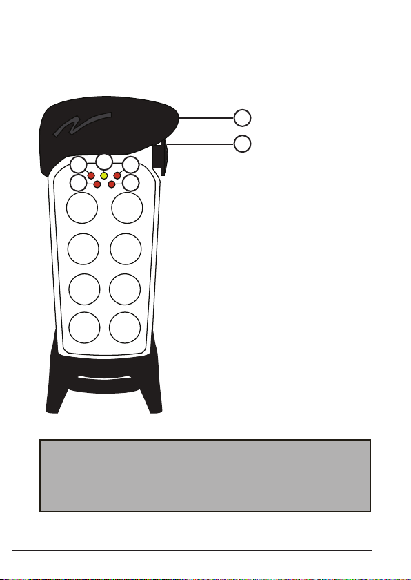
8-BUTTONS TRANSMITTER T7-2
1
2
4
3
1 2
1
3
5
7
5
76
2
4
1. Rubber cover
2. STOP button
3. red LED 1
4. yellow LED
5. red LED 2
6. red LED 3
7. red LED 4
6
8
STOP BUTTON TEST
IMPORTANT! We recommend that the functionality of the STOP
button is being tested at a regular basis: At a minimum, when used for
200 hours. Test the STOP button by pressing and pulling it out.
Frequency: 2405-2480 MHz.
8

Technical data T7-2 transmitter
NUMBER OF BUTTONS 8 x 2-step pushbuttons
BATTERIES 3 x 1.5V AA exchangeable
DEGREE OF PROTECTION IP65
NUMBER OF CHANNELS 16
SIZE 7.3 cm. x 17.8 cm./2.9 x 7 in.
(excl. rubber cover)
WEIGHT 250 g./ 0.55 lbs.
(excl. rubber cover, incl. batteries)
FREQUENCY 2405-2480 MHz.
Install batteries
1. Remove the battery cover (2 screws).
2. Put the batteries (3 x 1.5V AA
batteries) in.
3. Put back the battery cover (2 screws).
For optimum performance, use alkaline batteries.
3 x 1.5V AA
+
The rubber cover
The transmitter comes with a removable rubber
cover that helps prevent the transmitter from bumps, dirt and dust. The
rubber cover can be removed and wiped off.
Remove the rubber cover
1. Loosen the rubber cover, starting at the top.
2. Lift the transmitter up out of the rubber cover.
Replace the rubber cover
1. Place the transmitter in the rubber cover, starting at the bottom.
2. Put the rubber cover back on the transmitter.
9

STANDARD SETTINGS
DEFAULT STATE
• discontinuous radiotransmission
• no on/off function
The system will start transmitting as soon as the batteries are inserted,
the stop button is pulled out and a transmitter button is pressed. Radio
transmission will end when no transmitter button is being pressed.
START THE TRANSMITTER
1. Pull out the stop button.
The transmitter transmits when a transmitter button is pressed.
TURN THE TRANSMITTER OFF
1. Press the stop button.
NOTE! When the transmitter is active and the stop button is
pressed, all relays go off.
REGISTER THE TRANSMITTER IN THE RECEIVER
1-8 transmitters can be registered in the receiver.
1. Press the receiver Function button until red LED 7 lights up.
2. Press the receiver Select button until LEDs 1-5 light.
3. Press transmitter button 1, 1 step down, until LEDs 1-10 ash 3
times before going out.
10

ERASE ALL TRANSMITTERS FROM THE RECEIVER
1. Press the Function button until LED 7 lights.
2. Press the Select button until red LED 1-5 light. Keep pressed until
LED 7 and the relay LEDs 1-5 go out.
NOTE! If red LED 7 ashes slowly, one or several transmitters are still
registered in the receiver.
RELAY SETTINGS FOR OPERATING MODE 1
Transmitter button 1 (1st + 2nd step) activates relay 1
Transmitter button 2 (1st + 2nd step) activates relay 2
Transmitter button 3 (1st + 2nd step) activates relay 3
Transmitter button 4 (1st + 2nd step) activates relay 4
Transmitter button 5 (1st + 2nd step) activates relay 5
11

FCC IC INFORMATION
The user is cautioned that changes or modications not expressly
approved by the party responsible for compliance could void the user’s
authority to operate the equipment.
Toute modication apportée à cet appareil qui ne serait pas
approuvée expressément par (applicant name) peut invalider
l’habilitation de l’utilisateur à utiliser l’appareil.
This device complies with Part 15 of the FCC Rules and Industry
Canada licence-exempt RSS standard(s). Operation is subject to the
following two conditions:
(1) this device may not cause harmful interference, and
(2) this device must accept any interference received, including interference that may cause undesired operation.
L’appareil est conforme à la réglementation FCC, section 15 et Industrie
Canada RSS standard exempts de licence (s). Son utilisation est soumise
à deux conditions :
(1) L’appareil ne doit pas provoquer d’interférences nuisibles, et
(2) L’appareil doit supporter les interférences reçues, y compris les
interférences empêchant son fonctionnement correct.
12
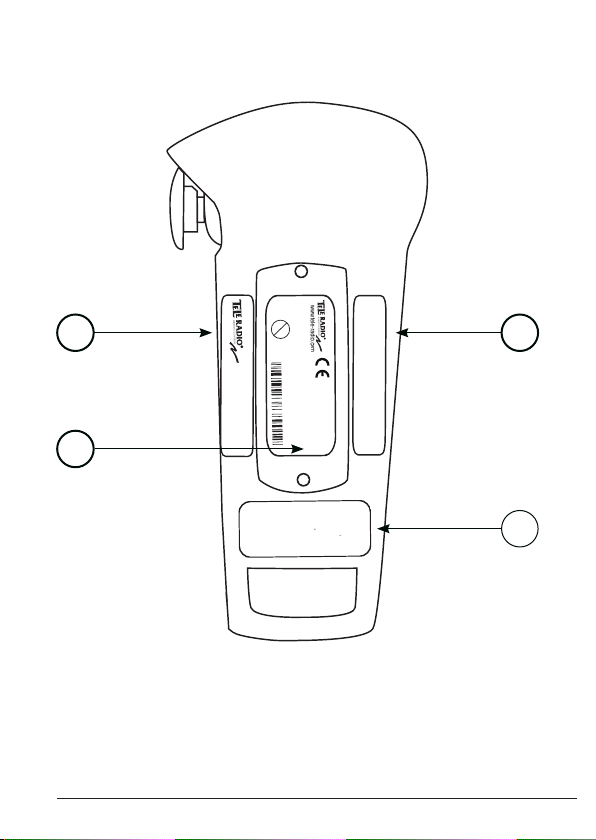
TRANSMITTER LABEL PLACEMENT
Model No.:
This
device
complies
with
part
1
5
of
the
FCC
Rules.
Operation
is
subject
to
the
fol
-
lowing
two
conditions: (1)
This device
may
not
cause
harmful
interference, and
(2) this
device
must
accept
any
interfe -
ence
received,
including
interference
that may cause
undesired operation.
2150
+
www.tele-radio.com
Freq.:2405-2408MHz
eq.:2405-2480MHz
Pb
Model: T00007-02
FCC ID: ONFC1010A
1
IC: 4807A-C1010A
Model No.: T00007-02
SN: XXXX
2
+
3
4
1.
2.
IC ID label
CE label
3.
FCC ID label
FCC information label
4.
13

BATTERY PRECAUTIONS
Observe the following general battery warnings.
• As batteries contains ammable substances such as
lithium or other organic solvents, they may cause
heating, rupture or ignition.
• Risk of explosion if battery is replaced with a battery of an incorrect type.
• Do not short circuit, disassemble, deform or heat batteries.
• Never try to charge a visibly damaged or frozen battery.
• Keep batteries out of reach of small children. Should a child swallow
a battery, consult a physician immediately.
• Avoid direct soldering to batteries.
• When discarding batteries, insulate the + and - terminals of batteries
with insulating/ masking tape. Do not put multiple batteries in the
same plastic bag.
• When improperly disposed, lithium batteries may short circuit,
causing them to become hot, burst or ignite.
• Store in a cool location. Keep batteries away from direct sunlight,
high temperature, and high humidity.
• Do not throw batteries into re.
!
DISPOSAL OF BATTERIES AND
ELECTRONICS
Improperly disposed electronics may harm public health and the environment. Batteries and electronic waste may contain toxic heavy metals. If
thrown away in the trash, the toxic compounds can leach into soil and
water, pollute lakes and streams, making them unfit for drinking,
swimming, fishing, and wildlife. Contact your local government’s recycling
or solid waste department for more information on proper disposal of
electronics in your region.
14

ROHS AND WEEE
In accordance with Directive 2002/95/EC on restriction
of the use of certain hazardous substances in electrical
and electronic equipment (RoHS) and Directive 2002/96/
EC on waste electrical and electronic equipment (WEEE),
Tele Radio strives to minimize the use of hazardous
materials, promotes reuse and recycling, and reduces
emissions to air, soil and water. When a commercially
viable alternative is available, Tele Radio strives to restrict
or eliminate substances and materials that pose an
environmental, health or safety risk.
GUARANTEE, SERVICE, REPAIRS AND
MAINTENANCE
The Tele Radio products are covered by a guarantee against material,
construction and manufacturing faults. During the guarantee period, Tele
Radio may replace the product or faulty parts. Work under guarantee
must be carried out by Tele Radio or by an authorized service centre
specied by Tele Radio. This is not covered by the guarantee: Faults
resulting from normal wear and tear. Parts of a consumable nature.
Products that have been subject to unauthorized modications. Faults
resulting from incorrect installation and use. Damp and water damage.
Repairs and maintenance must be carried out by qualied personnel.
Use spare parts from Tele Radio only. Contact your representative or
Helpdesk if you require service or other assistance. Keep the product in
a dry, clean place. Keep contacts and antennas clean. Wipe off dust using
a slightly damp, clean cloth. Never use cleaning solutions or high-pressure
water.
15

TELE RADIO AB
Sweden, Main office
Tel. +46 (0)31-748 54 60
e-mail: info@tele-radio.com
TELE RADIO SVERIGE
Sweden
Tel. +46 (0)31-724 98 00
e-mail: sverige@tele-radio.com
TELE RADIO LTD
England
Tel. +44 (0) 1625 509125
e-mail: england@tele-radio.com
www.tele-radio.com
TELE RADIO GmbH
Germany
Tel. +49 (0)94 51-944 8 550
e-mail: deutschland@tele-radio.com
TELE RADIO LLC
North America & Latin America
Tel. +1 (305) 459 0763
e-mail: america@tele-radio.com
TELE RADIO ASIA
China
Tel. +86-(0)592-3111168
e-mail: china@tele-radio.com
TELE RADIO BV
Benelux
Tel. +31-(0)70-419 41 20
e-mail: benelux@tele-radio.com
TELE RADIO TURKEY
Turkey
Tel. +90 216 574 22 94
e-mail: turkiye@tele-radio.com
TELE RADIO AS
Norway
Tel. +47-6933 4900
e-mail: norge@tele-radio.com
 Loading...