

Telepro HEIM-48 Installation & Operation Manual
Page : 1 / 14
INPUT MODULE
Installation & Operation Manual

Page : 2 / 14
----------------------------------------------------------------------------------NOTICE---------------------------------------------------------------------------------------
Read this manual thoroughly before using HEIM-48 INPUT Module and store in a safe place for reference.
Make sure that this manual is delivered to the final user.
The policiy of Telepro Enerji is one of continuous improvement .The right is reserved to alter the design on any structural
details of the products at any time without giving notice.
HEIM-48
HIGH EFFICIENCY INPUT MODULE
INPUT MODULE
Installation & Operation Manual
CPU VERSION 60.021
S
OFTWARE (ISPOPERA™) VERSION 6102.024
S
OFTWARE (ISPSIM™) VERSION 2.032.R21

Page : 3 / 14
INDEX
1. CONNECTIONS .............................................................................................................................. 4
1.1. Communıcatıon Termınal ................................................................................................................................................. 4
1.2. Power Supply .................................................................................................................................................................... 5
2. FRONT PANNEL DISPLAY FUNCTIONS ......................................................................................... 5
2.1. Device Status Dısplays ...................................................................................................................................................... 6
2.2. Communıcatıon Dısplays.................................................................................................................................................. 6
2.3. Input Dısplays ................................................................................................................................................................... 6
3. CONFIGURATION WITH ISPsimTM SOFTWARE TOOL .................................................................. 7
3.1. Software Confıguratıon ................................................................................................................................................... 7
3.2. Devıce Port Confıguratıon (Enablıng Communıcatıon) .................................................................................................. 7
3.3. Performıng Confıguratıon ............................................................................................................................................... 8
3.4. Sımulatıng Heım-48 ın the ISPSIM™ Tool ........................................................................................................................ 9
3.5. Heım-48 FW Fıle Upload .................................................................................................................................................. 9
4. HEIM-48 TECHNICAL SPECIFICATIONS ...................................................................................... 10
5. HEIM-48 INPUT MODULE MODBUS REGISTER MAP ................................................................. 11
6.HEIM-48 WIRING SCHEME........................................................................................................... 12
7.REMOTE CENTER MONITORING&EVENT RECORDING SOLUTION WITH HEIM-48 & HEEP-3000
.......................................................................................................................................................... 13
8. APPENDIX-1 INSTALLATION & OPERATION MANUAL REVISION HISTORY............................. 13
Page : 4 / 14
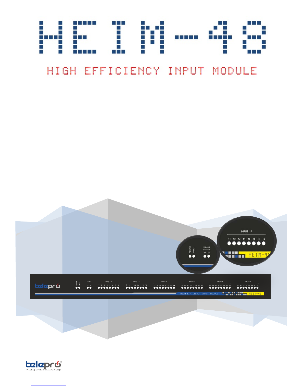
1. CONNECTIONS
All connections to HEIM-48 are made from the terminals on the rear of the unit .For wiring, 12 AWG (2.5mm2) wires
should be used.Always turn the device input power OFF before all service,maintenance and wiring actions.
Below indicated terminals of the device are grouped and of quick disconnec plug in type. All pins of each terminal could
be connected or disconnected to/from the device in one action. Power Supply should be turned OFF before connecting/
disconnecting the terminals.
There are 8pcs of terminal group located on the rear panle of the unit.
1. For MODBUS communication, there is a terminal of 3pins.(RS485 Terminal)
2. For power supply, there is a terminal of 4pins.(Supply Terminal)
3. There are 6 pcs of terminals of 9 pins for INPUT terminals. (The terminals which signals from the field are
connected)
1.1.
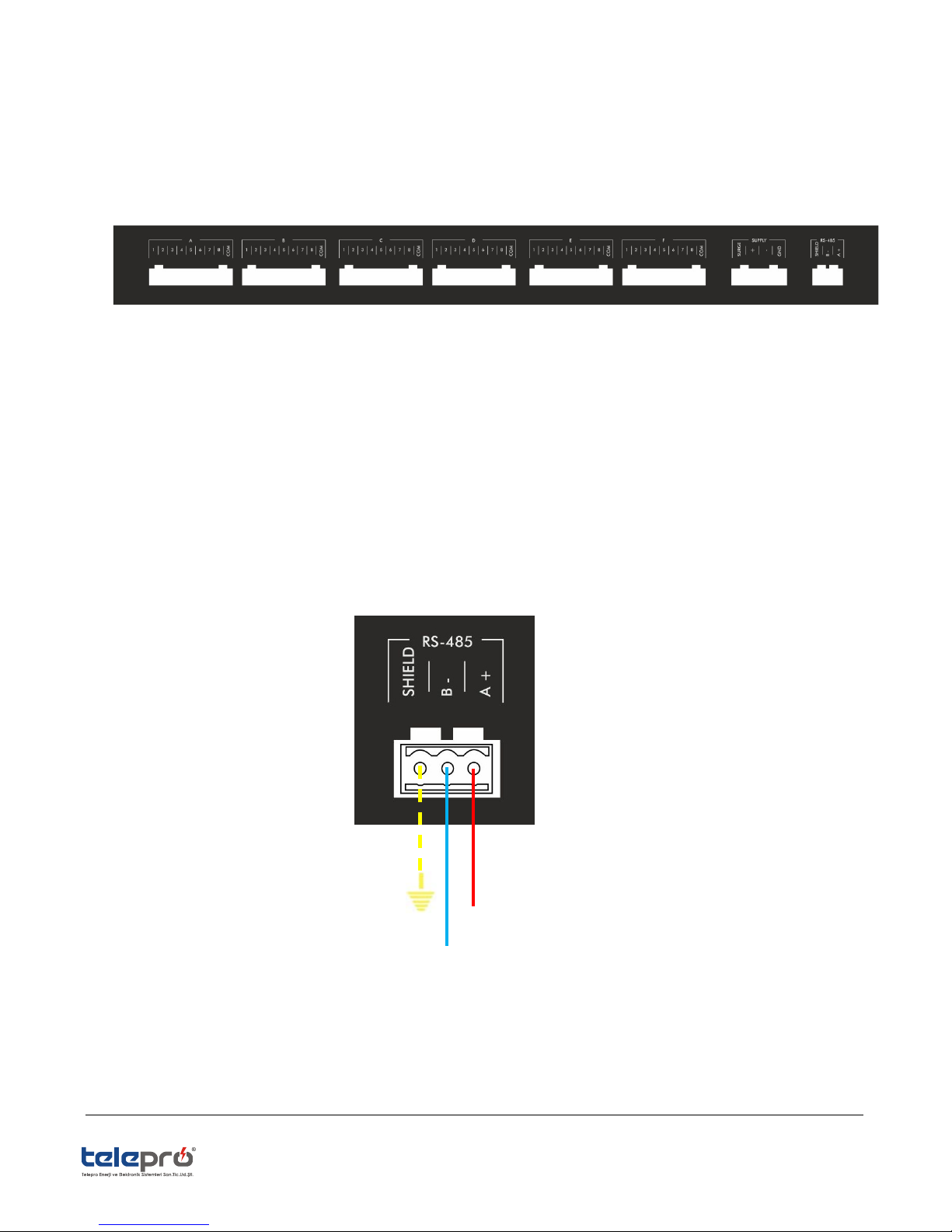
COMMUNICATION TERMINAL
HEIM-48 INPUT Module is providing communication feature via MODBUS-RTU protocol. It is possible to transfer field inputs
to the HEEP-3000 RTU or SCADA via RS485 physical medium with the help of Input Modul.It is easy to connect it from the
Administrative PC via RS485/232 converter. Corresponding port terminal connection should be done as seen below.
DATA (+)
DATA (-)
Page : 5 / 14
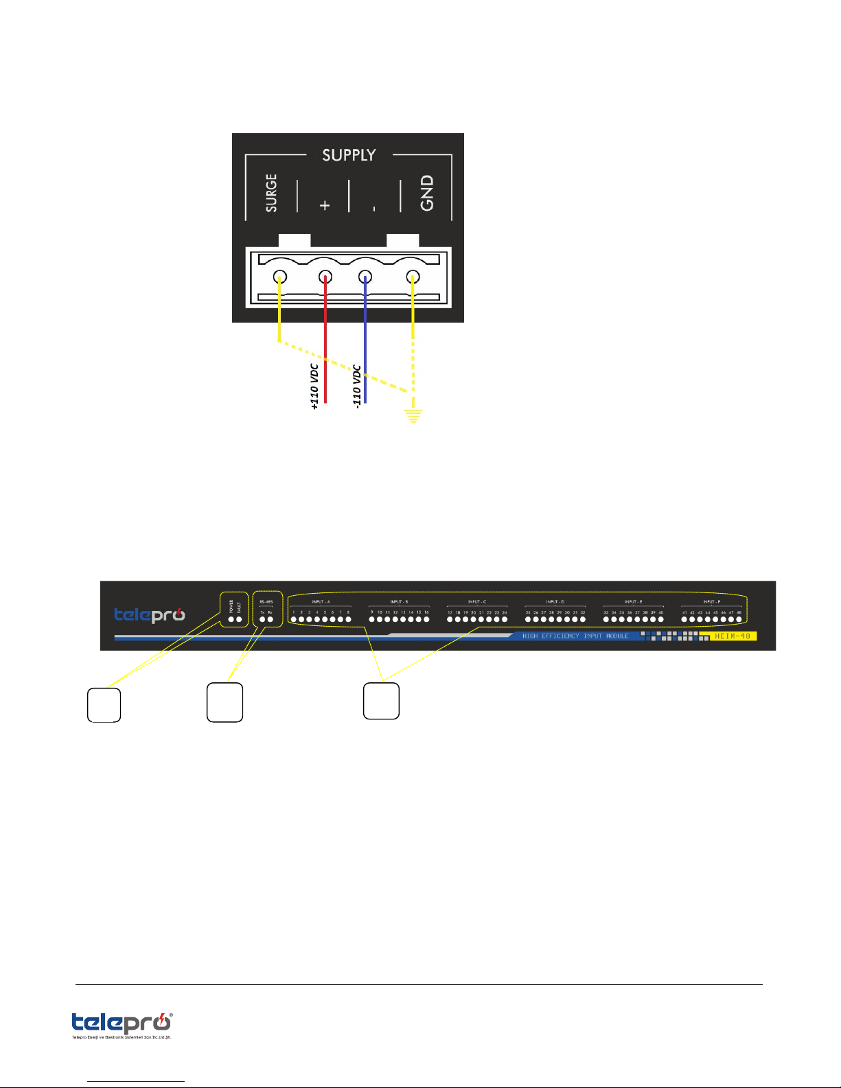
1.2. POWER SUPPLY
HEIM-48 Input Module is to be supplied with 110/220 VDC (optionaly 24/48VDC). Supply connection should be done as
seen below.
2. FRONT PANNEL DISPLAY FUNCTIONS
LED’s on the front panel of HEIM-48 are divided into 3 main groups.
1-Device Status LED Displays
2-Communication LED Displays
3-INPUT LED Displays
1
2
3
 Loading...