

TelePost Incorporated LP-200 Assembly Instructions Manual
1
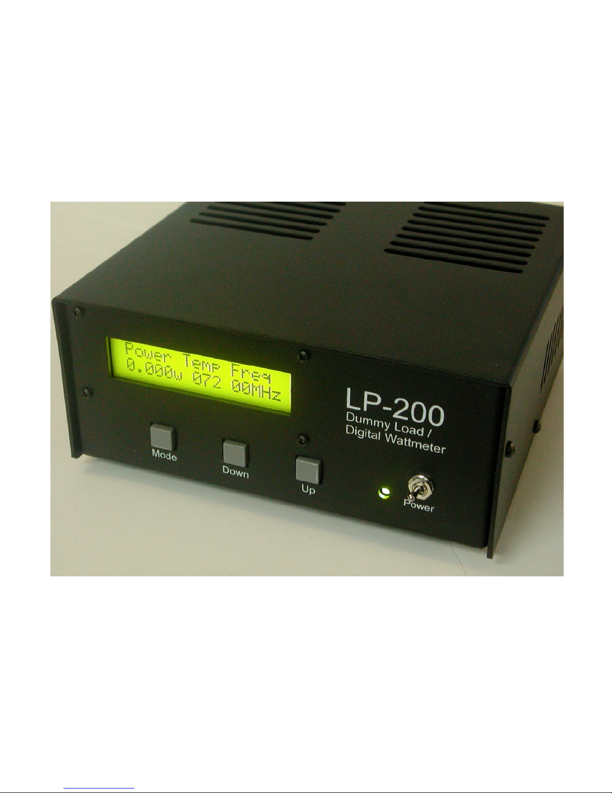
LP-200
Dummy Load / Wattmeter
Enclosure Retrofit Assembly Instructions
LP-200 is a trademark of TelePost Inc. Material in this document copyrighted ©2009 TelePost Inc.
March 2009
TelePost Incorporated
2
Introduction
These instructions will gude you through the installation of the LP-200 enclosure. There is really more
dissassembly than assembly involved, but it’s a straightforward process and should only take about an hour to
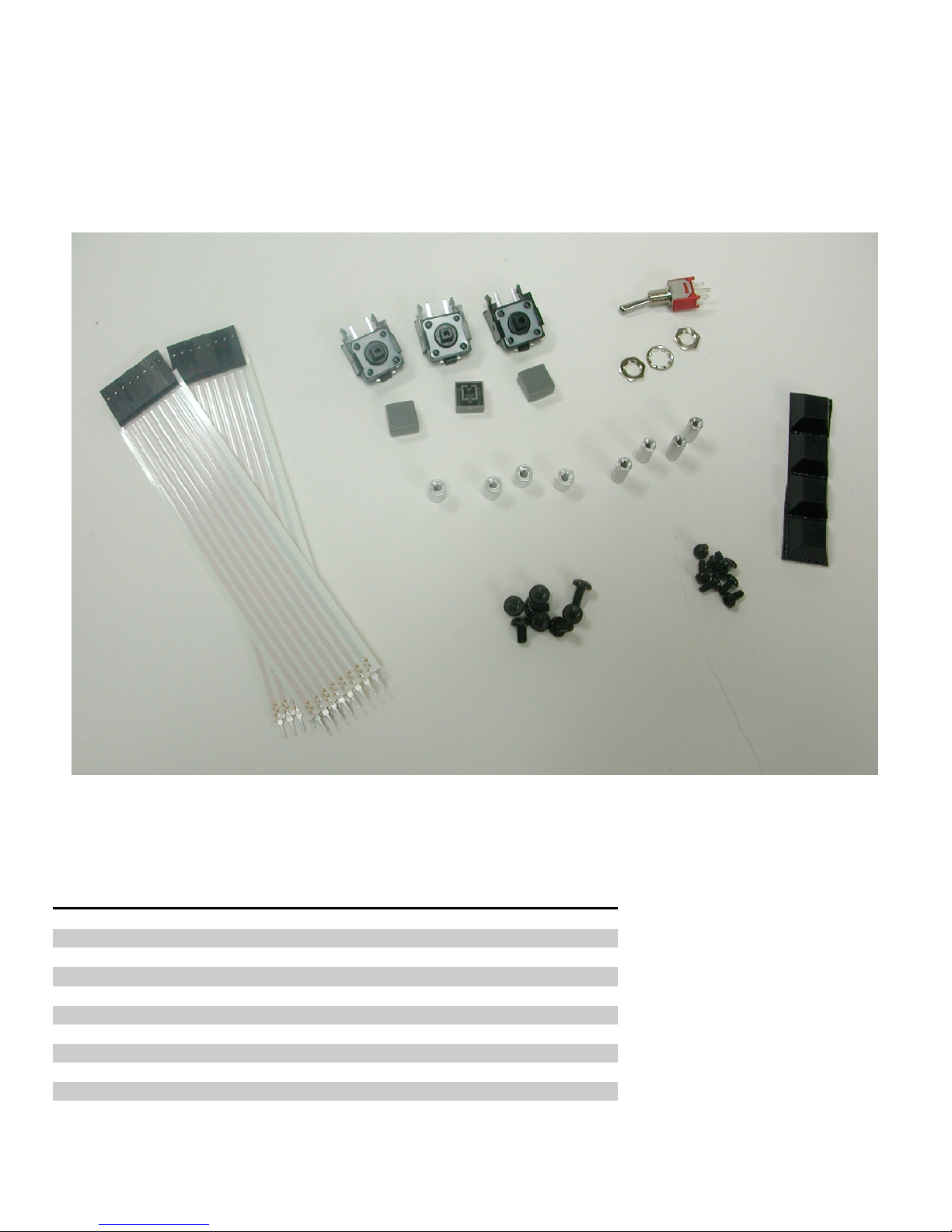
do. Before starting, you should inventory the parts. Here is a picture of all the parts except the enclosure top,
bottom, and six sheet metal screws that hold the top to the bottom.
Parts List - Subject to change without notice.
Quantity Designation Description
3 SW1,2,3 Right angle tactile switches w/keycaps
1 SW4 Toggle switch and hardware
2 1x8 ribbon cables
4 4-40 x ¼” threaded standoffs
4 2-56 x 3/8” threaded standoffs
8 4-40 x 3/16” machine screws
8 2-56 x 3/16” machine screws
1 Enclosure top
1 Enclosure bottom
6 #4 sheet metal screws
4 Rubber feet
 Loading...