

Page 1
1
LP-500 / LP-700
User Guide v3.1
Connections…
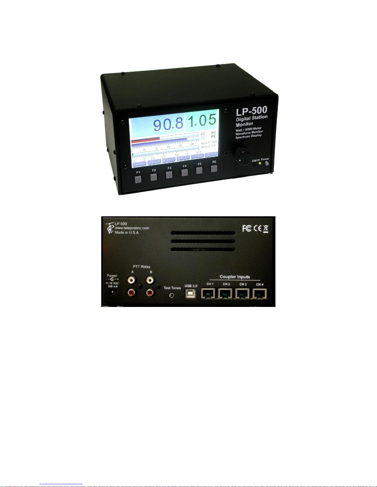
Power: 12-16 VDC @ 800 mA maximum, center pin positive, 2.5mm. The cable either has a white stripe on the positive wire, or ridges on the negative
wire, depending on the cable supplied. The meter also has a protection diode to prevent damage in case of reverse polarity. If unsure, use multimeter to
check the wiring before plugging it into the meter. The meter has a built in replaceable 1A fuse on the PCB for protection. We recommend a well
regulated supply with a 1A to 1.5A rating. An alternative is to use the accessory 12VDC jack on the rig if it can handle the current. You can also use a
12VDC power distribution strip like RigRunner connected to the main station DC supply. Sharing the meter power with other devices when the supply is
marginal could result in ripple caused by the high current switching of the LED backlight between on and off states.
PTT: For older amplifiers, loop the PTT (send, amp keying) between your amplifier and rig through the LP-500 using RCA connectors. Two isolated pairs
of connectors are provided for connecting two amplifiers. Use either pair for either amplifier.
Test Tones: Audio output for built in test tones. 3.5mm mono. Connects to the MIC or LINE input of the rig. An attenuator will be needed in the case of
mic input, as well as galvanic isolation (transformer). Interfaces designed for a sound card based RTTY setup should work well for this. We plan to offer
an interface box for this type of connection in the future, which will allow hot-switching between the mic and LP-500, isolation and level balancing
between them. This will ensure that testing can be done at normal speech levels.
USB 2.0: Connects to computer using standard USB cable (Type A to Type B connectors). Used for flashing firmware and interfacing to LP-500 VM and
Utility programs. Can be connected to USB 2.0 or 3.0 jacks on PC. No special drivers are necessary since the standard Windows drivers are used.
Couplers: Connect to corresponding jacks on the coupler(s) using supplied or user provided CAT5/6 shielded Ethernet cables. See Fig.1 below.
Page 2
2
Overview
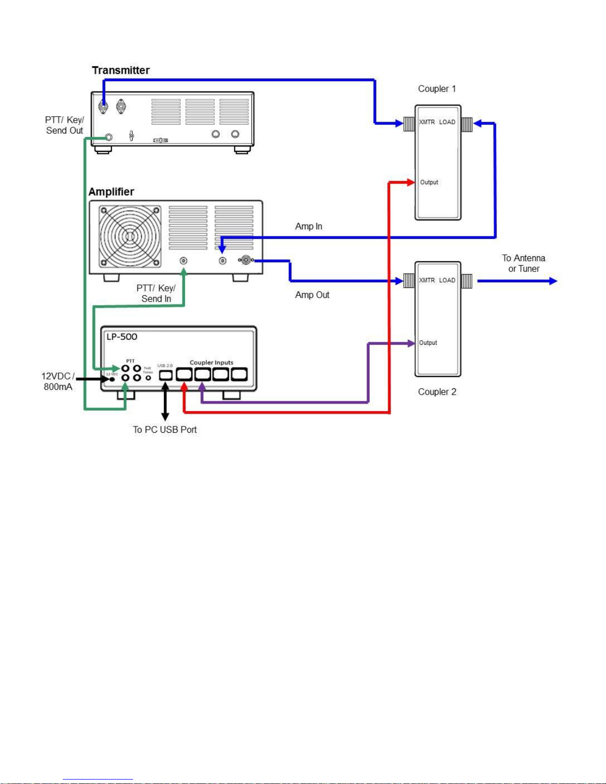
Fig.1. Shows installation with two couplers and PTT Alarm connections. The use of two couplers allows viewing of amplifier linearity with a trapezoidal
display. PTT Alarm connections are optional and designed mainly for older amplifiers with no built in protection.
The LP-500 Digital Station Monitor combines a state-of-the-art wattmeter and SWR meter with a task specific oscilloscope and spectrum analyzer, all
using a large, bright color TFT display. In the case of the LP-500, the display size is 5” diagonal. The LP-700 display size is 7” diagonal. Otherwise, the
two meters are the same. Any reference to the LP-500 in this manual also applies to the LP-700. The LP-500 also employs a low distortion audio signal
generator with a number of complex signals available, plus the ability to allow users to create their own test signals. The instrument can be used to
monitor the outputs of four different transmitters, or the inputs and outputs of two amplifiers as well as other combinations. The intent is for the user to be
able to monitor many aspects of his transmitted signal and ensure that his station is operating as cleanly as possible.
While it doesn’t completely replace dedicated oscilloscopes and spectrum analyzers, it performs almost all the tasks one would employ these
instruments to do, but does it much more conveniently, cost effectively and in many cases with better results.
While the LP-500 is a complex piece of test equipment, every effort has been made to make operation as simple as possible, with many automated or
linked functions. Operation of the LP-500 is mostly controlled through the six pushbuttons, but in the scope and spectrum modes there are a number of
touch screen controls, as well as a rotary digital encoder control. The six main buttons are associated with six “soft” buttons, which can also be
controlled via the touch screen.
The main modes of operation… Power/SWR meter, Waveform Scope and Spectrum Display… are controlled by the Mode button. The Mode button
remains in all modes, as does the Channel selection button. The 3rd button controls the range or gain of the meter in each mode. The other buttons are
soft keys whose function changes with mode.
A detailed list of modes and controls follows on the next pages, which will help the user get the most out of this meter.
Page 3
3
Power/SWR Mode…
Power/SWR
Waveform
Spectrum
CH Auto
CH 1
CH 2
CH 3
CH 4
Rng Auto
Rng 5
Rng 10
Rng 25
Rng 50
Rng 100
Rng 250
Rng 500
Rng 1K
Rng 2.5K
Rng 5K
Rng 10K
(per channel)
AL Off
AL On
(per channel)
Peak Hld
Average
Tune
Setup
Normal
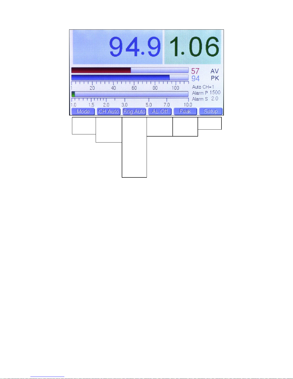
The above picture shows the Power/SWR mode, with menu choices listed below each button. The bottom choice in each list wraps around to the top.
Note: The pictures in this section were taken from v2.12 of the firmware and have changed slightly in later versions. The later versions have added a
peak hold power readout in the lower right.
Mode Button: Changes mode.
CH Button: Selects among the 4 coupler channels, and also offers an Auto Channel selection, which displays the channel with the highest power
reading. This mode is very useful for SO2R type contest operation. When in CH Auto, the current selected channel is displayed to the right of the SWR
bargraph, along with the current power and SWR alarm settings for that channel.
Range Button: Selects the desired bargraph range between 5W and 10KW in 11 steps, and also offers an Auto-Range choice.
The selection is indexed to the current channel selection and is saved in memory. As the range changes, the bargraph legends also change so that you
always graphically see the correct range and bargraph length. When changing to a higher range, there is some hysteresis built in so that the meter will
stay at the higher range unless power drops a certain percentage. This is done to prevent “hunting” on the edge of two ranges while operating, and
especially while tuning. Note: This choice can’t be changed when the CH button is in Auto.
Alarm Button: Selects the alarm status for each channel and is saved in memory. The alarm settings for the current selected channel are displayed to
the right of the SWR bargraph below the Auto CH display. This is true whether the channel is manually or automatically selected. These values are
entered on the Setup screen. If the alarm is tripped, the display indicates which channel tripped the alarm, and the chime sounds as well, with 1 chime
for CH1, 2 chimes for CH2, etc. The sequence repeats continuously until you stop transmitting, the fault is cleared or the alarm is set to OFF. The Alarm
P or Alarm S displays will change to red to indicate whether the trigger was due to a power fault or SWR fault. Note: This choice can’t be changed when
the CH button is in Auto.
Peak/Avg/Tune Button: Determines whether Average, Peak Hold or Tune power is fed to the large numeric power display. The hold time for Peak Hold
is adjustable in Setup. Tune is just peak hold with a very short hold time. Note: Smaller values of average and peak power are always displayed at the
end of the average and peak power bargraphs with 1W resolution.
Setup Button: This is a special button and displays a screen with all the adjustable user preference items. This will be covered as a separate mode later
in this guide. Tapping this button once changes to Setup mode, tapping again returns to Power/SWR mode. Tapping the Mode button will also return to
Power/SWR mode.
“Adjust” Knob: This controls an optical encoder which currently has two functions… to facilitate call sign entry in Setup by allowing the user to scroll
through alphanumeric characters, and to control the sweep rate in WFM mode when setting a User Preset. It does not function in factory presets. Slowly
turning this knob will result in smoother operation than rapid turning.
Page 4
4
Waveform / ‘Scope Mode…
Power/SWR
Waveform
Spectrum
CH 1
CH 2
CH 3
CH 4
Rng Auto
Rng 5
Rng 10
Rng 25
Rng 50
Rng 100
Rng 250
Rng 500
Rng 1K
Rng 2.5K
Rng 5K
Rng 10K
SSB F
SSB S
CW
PSK F
PSK S
User 1
User 2
User 3
Wfm
½ Trap
Scope
Wfm/Trap
AM Mod
Wfm/Pwr
2 Tone+
Wnoise+
Pnoise+
2 Tone
WNoise
Pnoise
400 Hz
1 kHz
User 1
User 2
User 3
User 4
Mode Button: Changes mode.
CH Button: Selects among the 4 coupler channels. CH Auto is not offered in the ‘scope mode to avoid confusion. The channel selection for the ‘scope
mode is independent of the Power/SWR mode.
Range Button: Selects the desired power range between 5W and 10KW in 11 steps, and also offers an Auto-Range choice.
The selection is indexed to the current channel selection and is saved in memory. As the range changes, the vertical voltage legend changes as well to
indicate actual peak voltage at the output connector of the coupler. As with the Power/SWR mode, there is some hysteresis built into the auto-ranging.
Sweep Button: Selects the horizontal sweep rate / scaling. There are 5 presets… which select a combination of sweep rate and trigger mode optimized
for the indicated mode, as follows:
SSB Fast... 1.0 msec/division, Normal trigger
SSB Slow… 2.0 msec/division, Normal trigger
CW… 1.0 msec/division, +/- trigger (more on this below).
PSK Fast… 5.0 msec/division, Normal trigger
PSK Slow… 10.0 msec/division, Normal trigger
Note: The +/- trigger mode displays a split screen of the CW waveform with positive edge triggering on the left side of the screen and negative edge
triggering on the right edge. This provides more resolution for viewing the detail of the leading and trailing edges of the keying waveform.
In addition, there are three USER sweep settings which allow the user to select his own combinations of sweep rate and trigger style. More on this in the
Touch Screen Controls section.
Test Tone Button: This button selects the desired test signal to be fed to the transmitter. Choices are:
2 Tone+… Two tones plus “subcarrier” (Spectrum Mode)
Wnoise+… White noise plus subcarrier (Spectrum Mode)
Pnoise+… Pink noise plus subcarrier (Spectrum Mode)
2 Tone… Standard two tone test signal
Wnoise… White noise
Pnoise… Pink noise
400 Hz… 400 Hz sine wave
1 kHz… 1 kHz sine wave
User 1,2,3,4… These select custom tones that the user can record and save to memory in standard .wav format.
The test tone output of LP-500 is unbalanced line level audio with a source impedance of 250 ohms. This can be directly fed to the line input of most
radios. We are developing an interface box which will convert this audio to mic level balanced output, with a switch and attenuator to allow matching the
LP-500 output to a microphone and switch between them.
Page 5

5
Waveform / ‘Scope Mode, Continued…
Trg Norm, Trg +, Trg -, Trg +/-, Trg Off
1.0 ms/div, 2.0 ms/div, 5.0 ms/div, 10.0 ms/div
Cursor 1, Cursor 2, Peak Marker, Cursor Off
Freeze, Unfreeze
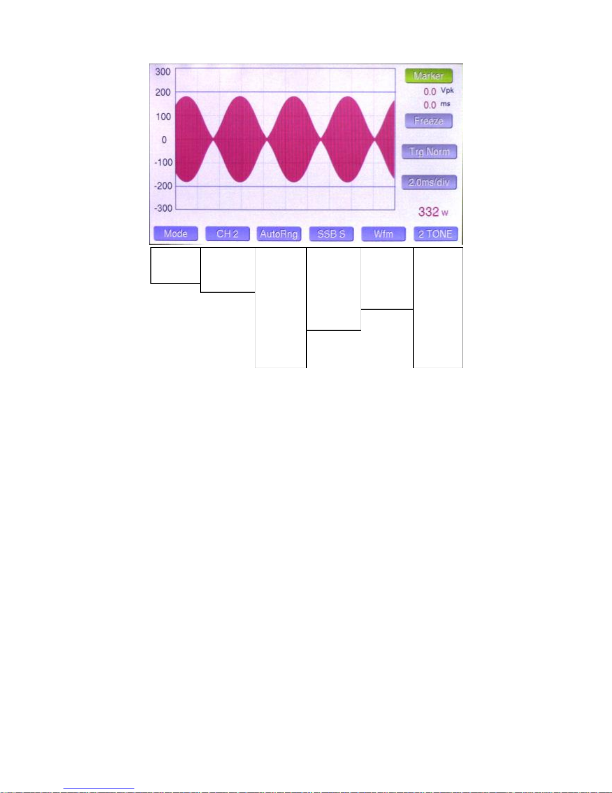
Descriptions below refer to these pictures and the one at the top of the previous page.
½ Trapezoid CW Envelope WFM / Trapezoid
AM Modulation WFM / PWR
Wfm Style Button: Selects the desired ‘scope display from these choices…
Wfm: Standard ‘scope display… shown top of previous page.
½ Trap: Top half of a trapezoidal display plots exciter output vs. amplifier output and displays a triangular image that easily shows when the output of the
amplifier becomes nonlinear, ie. flat tops and no longer provides the same gain as at lower power. Also shows other distortions of the input signal. Using
half the normal trapezoid allows displaying twice the vertical resolution.
Scope: Shows the modulation signal, ie. demodulated audio. Not shown.
Wfm/Trap: Split screen of the transmitted waveform on the left of the screen and trapezoid on the right side.
Wfm_Pwr: Displays the transmitted waveform on the left of the screen, and Power/SWR on the right side.
Touch Screen Controls…
The touch screen serves a couple functions. It adds additional buttons that the
user can access by pressing with his finger or a stylus, and it allows the user to
control cursors which allow the user to make voltage and time measurements.
Cursor Button: Pressing this button cycles through four cursor modes.
Selecting Cursor 1 displays a blue crosshair, which allows the user to set a
position on the waveform in either voltage or time, or both. The corresponding
voltage and the total time from the left edge of the display are displayed
numerically. Selecting Cursor 2 adds a second cursor with green crosshairs. In
this mode, the numerical readout shows the time difference between Cursor
1 and Cursor 2. The voltage displays 0. Pressing the cursor button again turns
on the Peak Pwr Markers. The fourth position is OFF.
Freeze Button: To aid in setting the cursors and making measurements,
pressing this button causes the waveform to freeze.
Trigger Button: This button selects the trigger mode when one of the USER sweep presets is selected. The selection is saved as a custom user preset.
The button only works when a USER preset is selected, but always displays the current trigger setting, even in factory sweep preset positions.
Sweep Button: Selects the desired sweep rate when the Sweep preset is set to one of the USER choices. The setting is saved in memory along with
trigger mode. The sweep rate can be modified by rotating the Adjust knob to any desired value.
Power Display: A numeric display below the Sweep button which shows the current transmitted power level. When moving Cursor 1, the power display
shows calculated power based on the cursor position rather than transmitted power.
Page 6

6
Spectrum Mode…
Power/SWR
Waveform
Spectrum
CH 1
CH 2
CH 3
CH 4
+65 dBm
+55 dBm
+45 dBm
2K Lin
5K Lin
10K Lin
2K Log
5K Log
10K Log
2
4
8
16
2 Tone+
Wnoise+
Pnoise+
2 Tone
WNoise
Pnoise
400 Hz
1 kHz
User 1
User 2
User 3
Filter On, Filter Off
Cursor 1, Cursor 2, Peak Marker, Cursor Off
Freeze, Unfreeze
Mode Button: Changes mode.
CH Button: Selects among the 4 coupler channels. CH Auto is not offered in the Spectrum mode to avoid confusion. The channel selection for the
Spectrum mode is independent of the Power/SWR mode.
Range Button: Selects the desired vertical gain from 0 dB to 20 dB. The button turns red and an error message appears if the signal is too strong.
Power range is between 5W and 10KW in 11 steps, and also offers an Auto-Range choice. The selection is indexed to the current channel selection and
is saved in memory. The “Ref(dBm)” readout below the Filter button updates to indicate the current 0 reference level at the top of the graph.
Span Button: Selects the desired span width in Hz. The choices are 2, 5 and 10 kHz with a linear scale, and 2, 5 and 10 kHz with a log scale. Linear is
generally used for tests like two tone IMD. Log is best for frequency response measurements.
Averaging Button: Selects the amount of averaging applied to the display. A higher setting provides lower noise, but is slower to respond and update.
Test Tone Button: This button selects the desired test signal to be fed to the transmitter. Choices are same as Waveform Mode.
Touch Screen controls…
Cursor Button: Pressing this button cycles through three cursor modes… Cursor 1,
Cursor 2 and no cursor. Selecting Cursor 1 displays a blue crosshair, which allows the
user to set a position on the waveform in either amplitude or frequency, or both. The
corresponding amplitude and frequency are displayed numerically just below the Cursor
button. Selecting Cursor 2 adds a second cursor with green crosshairs. In this mode, the
numerical readout shows the amplitude and frequency difference between Cursor 1 and
Cursor 2. Pressing the cursor button again turns on the Peak Pwr Markers. The fourth
position is OFF.
Freeze Button: To aid in setting the cursors and making measurements,
pressing this button causes the waveform to freeze.
Filter Button: This button activates a 200 Hz filter, which eliminates the “carrier” generated by some of the test tones, and shifts the display by 200 Hz
to restore proper values to the frequency scale. The filter button is automatically selected when any test tone that uses the 200 Hz subcarrier is selected,
but the filter can be manually turned on or off with any test tone selection. A description of the use of the 200 Hz subcarrier is explained in the waveform
/ ‘scope section of the Quick Start Guide.
Ref Display: Indicates the maximum signal level at the top of the display (“0” reference). This changes as the gain control is adjusted. The choices are
+65 dBm, +55 dBm and +45 dBm (approx. 3 KW, 300 W, 30W).
Ttl Pwr Display: This indicates the transmitted signal level in dBm. Note, this is a total peak power reading and will not always match the graphic
display, because it represents the sum of the power in all the frequency bins, rather than the power in any given frequency bin.
Page 7

7
Setup Mode…
Coupler CH x… LPC501
Power Alarm CH1, CH3… 60W
(Power Alarm CH2, CH4… 1500W
SWR Alarm CH x… 2.0
Power Mode… Net (F-R)
AL Threshold… 3W
SWR Rest Fmt… 1.00
Brightness… 100%
Peak Hold Time… 1 sec
Call: Pos Char… Dn 1 Up L
Scr Svr Timer… 5 min
Sleep Timer… 30 min
Scr Svr Reset… RF / Mode
Alarm Volume… 100%
Alarm Pitch… 700 Hz
Peak Resp… 100 usec
Hdwe Rev… v2.xx
Power/SWR
Waveform
Spectrum
CH Auto
CH 1
CH 2
CH 3
CH 4
Note: New option for Peak Response time
added after Alarm Pitch option. See below
for details
Mode Button: Changes mode
CH Button: Selects among the 4 coupler channels. There are three parameters that are channel specific… Coupler, Pwr Alarm and SWR Alarm. The
channel indicated next to each of these parameters is the one that is being adjusted.
Scroll Button: Allows the user to scroll down to the parameter he would like to change. This can be done by tapping repeatedly, or by holding the button
down for rapid scrolling through the parameters. When you get to the end of the list, the cursor moves back to the first parameter.
Adj Dn / Adj Up Buttons: Once the cursor is pointing to the parameter you want to adjust, using these buttons will allow you to adjust the setting up or
down. The exception is call sign entry. For this parameter, use the Dn button to select the horizontal position of the character you want to change, 1-9
from left to right. The use the knob to select the character (letter, numeral, punctuation) you want in that position. Pressing Up saves the character in the
call sign. NOTE: The character position counter automatically advances when you save a character, so you only need to use the Dn button if you want to
change one character.
Normal Button: Returns you to the Power/SWR screen
Here is a list of the various parameters and what they do, followed by a table of the default values.
Coupler… Selects the coupler model that is plugged into the selected channel…. LPC501, 502, 503, 504, 505
Power Alarm… Sets the power alarm trigger point for the selected channel… 10 to 2.5KW in 10W steps for LPC501, 20 to 5KW in 20W steps
for LPC502, 40 to 10KW in 40W steps for LPC503. This also sets the Peak Marker value.
SWR Alarm… Sets the SWR alarm trigger point for the selected channel… 1.50 to 5.00 in 0.50 steps
Power Mode… Selects power display type, either Net (F-R), ie. delivered power… or Fwd, ie. forward power.
AL/SWR Thresh… Minimum power required to activate the alarm system & SWR display. Use higher values to prevent false triggering from
other transmitters in multi-multi contest environments…1, 3, 10, 30, 100W. Higher values produce a more stable SWR display.
SWR Rest Fmt… Determines the graphic style for SWR display when not transmitting… 1.00, 0.00, Last (holds last value).
Brightness… Sets the screen brightness… 10% to 100% in 10% steps
Pk Hold Time… Sets the peak hold time in Peak power mode… 0.5, 1, 2, 3, 4, 5 seconds
Call: Pos Save… Allows the user to set a character position, and save the character to spell out his call sign. Adjust knob selects each character.
Scr Svr Timer… Sets the timeout values for the screen saver. Dims the screen to 10% after… 1, 2, 3, 4, 5, 10 minutes
Sleep Timer… Sets the timeout value for the screen to go to sleep… 10, 20, 30, 60 minutes and “Never Sleep”
Scr Svr Reset… Determines whether the meter will wake when you transmit, or if you wish to manually wake it with the Mode button.
Alarm Volume… Sets the volume of the alarm chimes… 10% to 100% in 10% steps. The chime sounds to help you set the right level.
Alarm Pitch… Sets the approx. pitch of the alarm chimes (the chimes are actually specified as musical notes)… ~300 to 900 Hz in 100 Hz steps
Peak Resp… Recently added screen. Allows the user to determine how the meter responds to very short peaks of power.
Hdwe Rev… Displays the current firmware revision.
The default settings for a standard LP-500 are shown below.
Page 8

8
Recommended Usage of the LP-500…
For the most part, you will find the LP-500 intuitive and easy to use. Below are some recommended settings for the various modes of the LP-500, and
how to maximize your experience using it.
Power/SWR Mode…
The key thing to remember in this mode is that the Range and Alarm buttons are indexed to the selected channel. This is true whether using manual or
auto channel selection. The first thing you should do is to verify that the default setup values work for you. If not, enter Setup and set the values to your
desired settings. Then, in the Power/SWR screen, step through each channel manually, and select the bargraph range that you would like, and which
channel should be the alarm trigger for the selected channel. Normally this would be the same channel as the selected channel, but there are a number
of circumstances where you might want different channels selected for power alarm and SWR alarm, as outlined in the Power/SWR section of this guide.
The programmed values for the trigger points are displayed to the right of the SWR bargraph. If the alarm is triggered, the Alarm P or Alarm S displays
will turn red to indicate whether the alarm was triggered by high power or high SWR.
Once you have the channels configured, you can select auto channel if you like. When in auto channel, the currently selected channel is displayed to the
right of the SWR bargraph. For most operating modes, Peak power should be selected, which displays and holds the peak value in the blue area of the
display. The hold time is programmable in Setup, from ½ second to 5 seconds.
Waveform/’Scope Mode…
Again, the key thing to remember here is that the Range is indexed to channel. For instance, if you typically use 100W on channel 1, you can manually
set the range to 30V/div. If you typically use 1500W on channel 2, you can manually set the range to 150V/div. You could also set both to AutoRng if you
like, and let the meter select the correct scaling.
Here are the recommended Sweep settings for the indicated modes…
SSB… SSB F or SSB S. The slower sweep shows more cycles of speech waveforms, but is a tad slower.
Two Tone Tests… SSB F or SSB S. The fast sweep displays 2 cycles of the test pattern, while the slow sweep displays 4.
CW… CW. Displays both the leading and trailing edges of the keying waveform, independent of keying speed.
PSK 31… PSK F or PSK S. The slower sweep rate shows 4 cycles of the PSK signal, the faster rate shows a bit more than 1 cycle.
You can experiment with different combinations to get the display you prefer, and you can create your own sweep presets for custom displays where you
can choose your own trigger mode and sweep rate, from 1 msec to 20 msec in 0.1 msec steps. Just as with a normal oscilloscope, the slower the sweep
rate the slower the response.
The Wfm Style button selects the type of waveform display that’s shown. Choices are as follows…
Wfm… Traditional envelope display of modulation.
½ Trap… Top half of trapezoidal display of exciter output vs. amplifier output
Scope… Traditional scope display of modulation waveform.
Wfm/Trap… Split screen of Wfm on the left and Trapezoid on the right.
AM Mod… Split screen of Wfm on the left, and bargraphs for positive and negative modulation on the right.
Wfm/Pwr… Split screen of Wfm on the left, and bargraphs for power and SWR on the right.
There are some warnings that you should be aware of regarding this mode…
In either the ½ Trap or Wfm/Trap display, you must connect a coupler at the input and output of your amplifier, as shown in the diagram on page 1 of this
guide. The couplers must be plugged into either CH1 / CH2 or CH3 / CH4, with the amplifier output on the higher number channel. When in either trap
mode, you must select the higher number channel. If you select the lower number channel, you will see an error message and the button will briefly turn
red. If the amplifier is off, or on the wrong band, you will receive another error indicating that the amplifier gain is low. The LP-500 assumes that the amp
should have a gain of at least 6 dB.
In AM Mod display, the LP-500 looks for pauses in speech to determine the carrier level. Typically, this happens when you first key up, before speaking,
but also happens anytime there is no modulation. The meter needs this info to calculate modulation percentages.
The test tones to use in the Wfm displays are 2 Tone for SSB testing and either 400 Hz or 1 kHz for AM testing. The other choices are specially
designed for the Spectrum mode, as explained in the Spectrum Mode section.
We will be posting some video tutorials on our LP-500 web page, www.telepostinc.com/lp500.html which will walk the user through various tests like
amplifier linearity using the trapezoid display, frequency response tests using the white noise signal, two-tone IMD tests, etc.
Spectrum Mode…
Before going through the settings, we need to address some factors affecting spectrum measurements. Notice that three of the test tones have a “+”
sign added, indicating that the signals include a subcarrier. These signals are used only in the Spectrum Mode. The purpose of this is to restore the
missing carrier when testing in SSB modes. Without this, the envelope detectors in the coupler would produce a highly distorted signal in the audio
realm, which is what we are really measuring in the Spectrum Mode. So, these test tones are really designed to produce a pseudo-AM signal when fed
to a SSB balanced modulator so that the detectors in the couplers can cleanly demodulate this into two tones and their distortion products. This is not
exactly the same as a traditional two-tone test, even though it looks similar. But it allows the use of standard type couplers over very wide frequency
ranges (up to microwaves if desired) without the complicated circuitry of an RF spectrum analyzer or expensive ADC circuits which can cover UHF
frequencies… or both.
Page 9

9
Recommended Usage of the LP-500, Continued…
Problem
Solution
Meter won’t boot past startup screen
Rotate Adjust knob. This is a bug caused by indecision (noise) in the
optical encoder on early meters (LP-500 serial number < 00030, LP-700
serial number <00018)). A free plugin mod is available to update the
encoder operation.
Meter screen flickers or tones are raspy
Insufficient power supply current capability
Ripple on patterns in ‘scope modes
Insufficient power supply regulation or chassis bonding
Low gain alarm in Trapezoid modes
Amplifier is off or not adjusted properly
Trapezoid vertical scale is low
Lower the Range setting, or select Auto
Trapezoid horizontal scale is low
Increase amplifier gain setting in LP-500
Channel alarm in Trapezoid modes
CH 2 or CH 4 must be selected for Trapezoid operation. Amplifier must be
connected to one of these channels.
Meter shows occasional high power peaks.
The solution depends on the source of the peaks and whether the user
wants to see them. Modest peaks can be caused by ALC overshoot in the
transmitter. Very large peaks could be caused by T/R relay arcs caused by
application of power before the relay has closed. Most rigs have an
adjustment to delay onset of power output after PTT is initiated.
In any case, the user can slow down the meter’s ultrafast response to
short spikes by choosing a longer Peak Resp time in SETUP.
Because the subcarrier must be stronger than the two test tones, this limits the peak power in the two tones, but still results in meaningful measurements
on a relative basis at full power, so that the user can see the degradation of the IMD products depending on amplifier settings, or when comparing one
amplifier to another. Note: The rig must be capable of passing 200 Hz for this mode to work. Most rigs will do this, or have SSB pass band options which
allow adjustment of the low frequency cutoff.
The Noise+ signal is especially useful in adjusting parametric equalizers in SSB modes. For AM
mode, a Noise signal is provided without the subcarrier. Keep in mind that the amplifier is being taxed
to the full power limit because of the power in the subcarrier signal, which is stronger than the
modulation signals. See picture at right…
In terms of settings, similar to what we saw in the other modes, the preamp gain settings are indexed
to the selected channel. Normally, the gain can be left at +65 dBm or +55 dBm depending on whether
you are using an amplifier, but occasionally when running very low power you may want to increase
gain to +45 dBm full scale. If you use too much gain, the gain button will turn red and you will see an
error message.
There are three span settings… 2.5, 5 and 10 kHz, with the option of either linear or logarithmic frequency scaling, with a 5X multiplier also available for
the 2.5 & 5 kHz Linear scales. Here are some recommended choices for some common tests…
Two Tone SSB… 2.5 kHz linear
Freq. Response… 5 or 10 kHz log
CW Bandwidth… 500 to 1000 Hz linear
SSB or AM Bandwidth… 5 kHz log
There is also a Span Multiplier button which decreases the span by a factor of 5:1 in the two narrowest ranges. Therefore, 2.5 kHz becomes 500 Hz and
5 kHz becomes 1 kHz. The span multiplier works in Linear modes and is useful for measuring the spectral width of CW or PSK signals. It should be
noted than when the multiplier is on, it slows the meter own considerably. We recommend setting the averaging to 2. It is self-cancelling in that the
Spectrum mode always starts with the multiplier off. This is done to eliminate starting in a slow mode.
When making IMD tests, it is advisable to use +55 dBm reference gain setting when doing tests at 100W, or +45 dBm reference gain setting when doing
tests at QRP levels. This not only lowers the noise floor, but places the signal and distortion products in a more linear range of the coupler detector. You
should try to set the reference setting so that the two tones are at an indicated level of -10 to -20 dBm relative to the reference at the top of the display.
The Filter button should be On whenever using a test signal with subcarrier to filter out the carrier artifacts and to restore the proper frequency scaling to
shift the display by the carrier frequency. This is automatic when selecting these test signals, but can be manually selected or deselected.
The averaging button can be set to taste. The higher the setting, the lower the noise floor, but also the slower the response. For frequency response
measurements with white noise, it should be set to 8 or 16 to make it easier to see the curve.
Troubleshooting…
Page 10

10
LP-500 VM (Virtual Meter) Software for Windows
Above images are screen captures from the VM software. These images are scaled down for display in this manual, but fill an 800 x 480 pixel window on
the user’s computer monitor. This is, of course, the native resolution of the LP-500. With typical size monitors, this provides a large and very readable
display, which can be viewed either locally or remotely over a LAN or the Internet.
In general, the VM works just like the meter itself, with all of the controls and displays mirroring the ones on the meter. The VM can run simultaneously
with the meter and is fully bidirectional, meaning that any change at the meter will be reflected in the VM and vice versa. This includes the displays and
controls. For those with limited space for the LP-500, this provides a much larger display, and higher resolution. The VM is a free download, like all
TelePost software, and very easy to set up. If the meter is plugged into a USB jack on the PC, starting the VM will automatically connect to it.
The VM software is a work in progress, but it is available for downloading on the LP-500 web page. The current version (1.06) is mostly functional except
for the following things…
Power/SWR screen: Alarm settings are not shown, Setup screen npt functional
WFM screen: Cursors / Freeze not functional, AM & Power/SWR split screens not functional
Spectrum screen: Cursors / Freeze not functional
This is beta software, use at your own risk.
Page 11

11
Using mikroBootloader to flash new firmware:
Download the mikroBootloader software from our LP-500 web page, as well as the latest firmware. Unzip and install the software, then unzip the
firmware file and save the resulting hex file to a convenient place where you might want to save future firmware versions as well. In this example, we’ll
use LP500_v213.hex, and we’ll save it to the folder C:\Users\Shack\Downloads\LP-500_firmware\.
Figs. 1-6 (upper left to lower right)
Page 12

12
Using mikroBootloader to flash new firmware, Continued:
Plug the LP-500 into a USB 2.0 port on the PC using the supplied USB cable. No special drivers are needed for the LP-500. It uses the standard
Windows USB HID drivers and should be instantly recognized by the PC with the usual USB connect sound.
Start the mikroBootloader program (Fig. 1), then turn the LP-500 on, or power cycle the meter if it’s already on. This starts the bootstrap loader in the
meter. The several seconds of black you normally see when the meter is turned on is actually the bootstrap loader running and waiting for a possible
request.
In the Device window of the software you should see "LP-500" for a few seconds indicating that it has found the LP-500 with its bootstrap loader running.
The MCU Type window simply indicates that the microcontroller in the LP-500 is from the PIC32 family, which matches the code in the hex file. While
“LP-500” is being displayed, click on Connect. The Connect button should immediately change to Disconnect if the software was successful connecting
to the meter, (Fig. 2). If not, turn the meter off and back on and try again. You have a window of a few seconds to connect to the meter, otherwise it will
continue to the operate mode. You can always get the bootloader to restart by power cycling the meter.
After the program connects to the meter, click on Browse for HEX. Find and open the hex file that you previously saved (Fig. 3). In the History Window
you will see that the file has been opened (Fig. 4).
Then click on Begin uploading. It should take about 10 seconds to upload the new firmware, as indicated by the progress bar (Fig. 5). WARNING: Don’t
remove power from the meter or interrupt the loading while it’s in progress.
Then you'll get a message that the meter is restarting (Fig. 6). After that, the meter will restart with the new firmware. After the meter boots up and goes
to the main screen, it's a good idea to power cycle it again to make sure everything is properly initialized.
Page 13

13
Preliminary Specifications… (Using standard LPC501 Coupler)
General
Power Range… 0.1 W to 3 KW PEP / 1500W average power
Absolute Power Accuracy… Better than 3% at 7 MHz, NIST traceable
< 0.1 dB variation from 1.8 to 30 MHz, slightly lower on 6m
Reduced accuracy below 5W
SWR Range… 1.00 to 9.99
SWR Accuracy… Within 5%, 1.8 to 30 MHz, slightly worse on 6m.
Bar Graph Resolution... 600 steps for Each Range, Manual or Auto-Ranging
Directivity… >30 dB, 1.8 to 54 MHz.
Return Loss … >40 dB, 1.8 to 54 MHz.
Number of Channels… 8 simultaneous (FWD & REF power for 4 couplers)
A/D Converter 16-bit / 200ksps, with 2X to 16X oversampling.
DAC Resolution… 18-bit, 96 dB SNR
Screen Update… 5 Hz to 25 Hz, depending on mode, sweep/span setting.
Sampling Rate… 3 ksps to 25 ksps, depending on mode, sweep/span setting.
Display Resolution 800 x 480 pixels (WVGA)
Display Type TFT with White LED Backlight
Display Size LP-500: 5" Diagonal, LP700: 7" Diagonal
Test Tone Output… 250 ohms, 500mV RMS, unbalanced, 0.01% THD
Power Requirements… 12-16VDC @ 800 mA maximum
Size… LP-500: 8.125"W x 6.1"D x 4.38"H (20.6cm x 15.5cm x 11.1cm)
LP-700: 10.125"W x 6.1"D x 5.63"H (25.7cm x 15.5cm x 14.3cm)
Scope
Sweep Rate … 1.0 to 20.0 ms/division in 0.1 ms steps
5 Factory Presets and 3 User Adjustable Presets
Display Modes … 6, including 3 split screens
Trigger Modes … 5
AM Modulation % … 0 to 150 positive, 0 to 100 negative.
Cursors … 2, measuring peak voltage and time (ms)
Markers... 2, adjustable to show preset power limits
Spectrum
Frequency Spans... 2.5, 5.0 & 10.0 kHz, w/linear or log scaling
Span Multiplier... 5x (500 & 1000 Hz, linear)
RBW… 1 to 20 Hz, depending on span
Averaging… 2X to 16X
Reference Level… +45, +55, +65 dBm Full Scale
ADC Dynamic Range… > 90 dB
Coupler Dynamic Range... Up to 80 dB, depending on modulation type
Cursors … 2, measuring peak power (dBm) and frequency (Hz)
Marker... 1, adjustable to show preset power limit
LPC502 Coupler
Power Range… 5 KW PEP / 2500W average
Flatness… < 0.1 dB variation from 1.8 to 30 MHz, slightly lower on 6m
LPC503 Coupler
Power Range… 10 KW PEP / 5KW average power
Flatness… < 0.1 dB variation from 1.8 to 30 MHz
Warranty
LP-500 is warranted against failure due to defects in materials and workmanship for two years from the date of purchase from TelePost Inc. Warranty
does not cover damage caused by abuse, accident, improper or abnormal usage, improper installation, alteration, lightning or other incidence of
excessive voltage or current.
If failure occurs within the warranty period, return the LP-500 to TelePost Inc. at your shipping expense. The device will be repaired or replaced, at our
option, without charge, and returned to you at our shipping expense. Repaired or replaced items are warranted for the remainder of the original warranty
period. )
TelePost Inc. shall have no liability or responsibility to customer or any other person or entity with respect to any liability, loss or damage caused directly
or indirectly by use or performance of the product or arising out of any breach of this warranty, including, but not limited to, any damages resulting from
inconvenience, loss of time, data, property, revenue or profit, or any indirect, special incidental, or consequential damages, even if TelePost Inc. has
been advised of such damages.
Under no circumstances is TelePost Inc. liable for damage to your amateur radio equipment resulting from use of the LP-500, whether in
accordance with the instructions in this Manual or otherwise.
Page 14

14
Compliance Statements…
LP-500 & LP-700 have been tested and fully documented in accordance with the following standards…
ANSI C63.4 – Radio Noise Emissions 2003.12
CFR47 FCC Part 15, SubPart B, Class B limits
AHD/SEI test procedures TP0101LC, TP0102RA
EN55022 ITE Disturbance 2005.11
EN61000-6-3 Generic 2007.2
EN61326-1:2006 (E)
EN61000-4-2
EN61000-4-3
Tests were conducted at the following accredited test facilities…
University of Michigan Radiation Laboratory, Ann Arbor, MI
AHD LC EMC Lab, Sister Lakes, MI – NVLAP LAB CODE 2001290
NOTE: This equipment has been tested and found to comply with the limits for a Class B digital device, pursuant to part 15 of the FCC Rules. These
limits are designed to provide reasonable protection against harmful interference in a residential installation. This equipment generates, uses, and can
radiate radio frequency energy and, if not installed and used in accordance with the instruction manual, may cause harmful interference to radio
communications. However, there is no guarantee that interference will not occur in a particular installation. If this equipment does cause harmful
interference to radio or television reception, which can be determined by turning the equipment off and on, the user is encouraged to try to correct the
interference by one or more of the following measures:
i. Reorient or relocate the receiving antenna.
ii. Increase the separation between the equipment and receiver.
iii. Connect the equipment into an outlet on a circuit different from that to which the receiver is connected.
iv. Consult the dealer or an experienced radio/TV technician for help.
TelePost Inc. declares that the product:
Product Name: Digital Station Monitor
Model Number:LP-500 / LP-700
Conforms to the following Product Specifications:
EN 55022: 1998 Class B
following the provisions of the Electromagnetic Compatibility Directive 89/336/EEC
Industry Canada Compliance Statement
Canada Digital Apparatus EMI Standard
This Class B digital apparatus meets all the requirements of the Canadian Interference-Causing Equipment Regulations.
Cet appareil numerique de la classe B respecte toutes les exigences du Reglement sur le material brouilleur du Canada.
LP-500 / LP-700 are 100% RoHS compliant for all parts and manufacturing processes.
Federal Communications Commission
Statement (USA)
European Union Declaration of Conformity
Copyright and Trademark Disclosures
LP-500 & LP-700 are trademarks of TelePost Inc. Windows® is a registered trademark of Microsoft Corporation.
Material in this document copyrighted ©2015, 2016 TelePost Inc. All rights reserved. All firmware and software used in the LP-500 & LP-700, VM and
Utility programs copyrighted ©2015, 2016 TelePost Inc. All rights reserved.
 Loading...