

Page 1

USER’S MANUAL
FOR THE
TRULINK
WIRELESS INTERCOM
SYSTEM
®
“THIS MANUAL INCLUDES TELEPHONICS PROPRIETY DATA AND SHALL NOT BE
DUPLICATED, USED, OR DISCLOSED, IN WHOLE OR IN PART.”
TM115007 Rev A (04/07)
April 2007
Prepared by:
TELEPHONICS CORPORATION
815 Broad Hollow Road
Farmingdale, New York 11735
USA
Page 2

T ELEPHONICS C ORPORATION Document No.: PC7155H0
Revision #
USER’S MANUAL
FOR THE
TRULINK
®
WIRELESS INTERCOM
SYSTEM
Copyright © 2007 Telephonics Corporation
Publication No.: TM115007
All Rights Reserved
Printed in U.S.A.
Telephonics Corporation
815 Broad Hollow Road, Farmingdale, New York 11735
Telephone: (877) 517-2327 Fax: (877) 755-7701
TM1150007 REV A (04/07)
USE OR DISCLOSURE OF DATA CONTAINED ON TH IS PAGE IS SUBJECT TO THE
RESTRICTION ON THE TITLE PAGE OF THIS DOCUMENT.
Page 3

T ELEPHONICS C ORPORATION Document No.: PC7155H0
Revision #
FCC COMPLIANCE
This device complies with part 15 of the FCC Rules. Operation is subject to the following
two conditions: (1) This device may not cause harmful interference, and (2) this device
must accept any interference received, including interference that may cause undesired
operation.
Changes or modifications not expressly approved by the party responsible for compliance
could void the user’s authority to operate the equipment.
This equipment has been tested and found to comply with the limits for a Class B digital
device, pursuant to part 15 of the FCC Rules. These limits are designed to provide
reasonable protection against harmful interference in a residential installation. This
equipment generates, uses and can radiate radio frequency energy and, if not installed and
used in accordance with the instructions, may cause harmful interference to radio
communications. However, there is no guarantee that interference will not occur in a
particular installation. If this equipment does cause harmful interference to radio or
television reception, which can be determined by turning the equipment off and on, the
user is encouraged to try to correct the interference by one or more of the following
measures:
Reorient or relocate the receiving antenna.
Increase the separation between the equipment and receiver.
Connect the equipment into an outlet on a circuit different from that to which the receiver is
connected.
Consult the dealer or an experienced radio/TV technician for help.
TM1150007 REV A (04/07)
USE OR DISCLOSURE OF DATA CONTAINED ON TH IS PAGE IS SUBJECT TO THE
RESTRICTION ON THE TITLE PAGE OF THIS DOCUMENT.
Page 4

T ELEPHONICS C ORPORATION
C
OMMUNICATION S YSTEMS D IVISION
DOCUMENT COMPATIBILITY
PRODUCT/PROJECT REVISIONS/VERSIONS
User’s Manual Rev A
LIST OF EFFECTED PAGES
REVISION DATE REASON FOR CHANGE PAGES EFFECTED
A
04/07 Original Issue
TM1150007 REV A (04/07) i
USE OR DISCLOSURE OF DATA CONTAINED ON TH IS PAGE IS SUBJECT TO THE
RESTRICTION ON THE TITLE PAGE OF THIS DOCUMENT.
Page 5

T ELEPHONICS C ORPORATION
C
OMMUNICATION S YSTEMS D IVISION
REVISION HISTORY SHEET
REVISION
DESCRIPTION
A Original
APPROVAL DATE
TM1150007 REV A (04/07) ii
USE OR DISCLOSURE OF DATA CONTAINED ON TH IS PAGE IS SUBJECT TO THE
RESTRICTION ON THE TITLE PAGE OF THIS DOCUMENT.
Page 6

T ELEPHONICS C ORPORATION
C
OMMUNICATION S YSTEMS D IVISION
TABLE OF CONTENTS
PARAGRAPH
CHAPTER 1 GENERAL DESCRIPTION
1.1 INTRODUCTION.....................................................................................................1-1
1.2 DEFINITIONS AND ABBREVIATIONS ...............................................................1-1
1.2.1 Definitions of Terms Used........................................................................................1-1
1.2.2 Abbreviations and Acronyms....................................................................................1-1
1.3 TRULINK DESCRIPTION ......................................................................................1-2
1.4 NETWORK CONFIGURATION.............................................................................1-2
1.5 CAPABILITIES........................................................................................................1-2
1.6 TRULINK EQUIPMENT .........................................................................................1-3
CHAPTER 2 OPERATION
2.1 OVERVIEW..............................................................................................................2-1
2.2 PHYSICAL DESCRIPTION ....................................................................................2-1
2.3 BATTERIES .............................................................................................................2-1
2.3.1 Installing/Changing...................................................................................................2-1
2.3.2 Battery Type..............................................................................................................2-2
2.3.3 Low Battery Warning................................................................................................2-3
2.3.4 Charging the TPT......................................................................................................2-3
2.4 ANTENNA................................................................................................................2-6
2.5 HEADSET.................................................................................................................2-6
2.6 TPT STATUS AND INDICATORS.........................................................................2-6
2.6.1 Visual Indicators .......................................................................................................2-6
2.6.2 Audible Indicators.....................................................................................................2-9
2.6.3 SynVoice Phrases......................................................................................................2-9
2.7 TPT OPERATION..................................................................................................2-11
2.7.1 Introduction to TPT Man-Machine Interface..........................................................2-11
2.7.2 Power ON/OFF .......................................................................................................2-11
2.7.3 Start-Up...................................................................................................................2-11
2.7.3.1 Starting a Network ..................................................................................................2-12
2.7.3.2 Logging On to a Network........................................................................................2-12
2.8 SETTINGS..............................................................................................................2-13
2.8.1.1 CHANNEL Setting for TPT....................................................................................2-13
2.8.1.2 VOX Setting............................................................................................................2-14
2.8.1.3 KEY LOCK Setting.................................................................................................2-14
2.8.1.4 LED Setting.............................................................................................................2-14
2.8.1.5 ORDER CHANGE MASTER Setting ....................................................................2-15
2.8.1.6 ORDER SYNCHRONIZE ACCESS POINT Setting (Changing TAP Channel)...2-15
2.8.2 Talking on the Network...........................................................................................2-16
2.8.2.1 Transmission Rejection...........................................................................................2-16
2.8.2.2 Transmission Indication..........................................................................................2-16
2.8.3 Volume Adjustment ................................................................................................2-16
2.8.4 Out of Range ...........................................................................................................2-16
2.8.5 Key-Click ................................................................................................................2-17
2.8.6 Power-On BIT Failure.............................................................................................2-17
2.9 TPT CHECK OUT PROCEDURE .........................................................................2-17
TITLE PAGE
TM1150007 REV A (04/07) iii
USE OR DISCLOSURE OF DATA CONTAINED ON TH IS PAGE IS SUBJECT TO THE
RESTRICTION ON THE TITLE PAGE OF THIS DOCUMENT.
Page 7

T ELEPHONICS C ORPORATION
C
OMMUNICATION S YSTEMS D IVISION
TABLE OF CONTENTS
PARAGRAPH
CHAPTER 3 TRULINK ACCESS POINT
3.1 OVERVIEW..............................................................................................................3-1
3.2 PHYSICAL DESCRIPTION ....................................................................................3-2
3.3 TAP INSTALLATION .............................................................................................3-2
3.3.1 Mounting...................................................................................................................3-2
3.3.2 Connections...............................................................................................................3-3
3.3.2.1 Power Connector.......................................................................................................3-3
3.3.2.2 Antenna Connector....................................................................................................3-3
3.3.2.3 Audio Connectors......................................................................................................3-3
3.3.2.4 Data Connectors........................................................................................................3-4
3.4 TAP OPERATION....................................................................................................3-4
3.4.1 Power ON/OFF .........................................................................................................3-4
3.4.2 Echo Elimination Procedure......................................................................................3-4
3.4.3 ORDER SYNCHRONIZE ACCESS POINT Setting (Change TAP Channels).......3-5
3.4.4 ORDER CHANGE MASTER Setting ......................................................................3-5
3.4.5 Logging on to a Network ..........................................................................................3-6
3.4.6 Status Indications ......................................................................................................3-6
3.4.6.1 Power-On BIT Failure...............................................................................................3-6
3.5 TAP CHECK OUT PROCEDURE...........................................................................3-7
TITLE PAGE
CHAPTER 4 TRULINK DUAL PORT TRANSCEIVER
4.1 OVERVIEW..............................................................................................................4-1
4.2 PHYSICAL DESCRIPTION ....................................................................................4-2
4.3 OPERATION ............................................................................................................4-2
4.3.1 ICS Interface .............................................................................................................4-3
4.3.2 Logging on to a Network ..........................................................................................4-3
4.4 DUAL PORT TRANSCEIVER CHECK OUT PROCEDURE................................4-4
CHAPTER 5 TRULINK SUPPORT STATION
5.1 OVERVIEW..............................................................................................................5-1
5.2 PHYSICAL CHARACTERISTICS..........................................................................5-1
5.3 CHARGE INDICATION..........................................................................................5-2
5.4 BIT INDICATION....................................................................................................5-3
5.5 TPT CHANNEL SELECTION.................................................................................5-3
5.6 TSS CHECK OUT PROCEDURE............................................................................5-4
APPENDIX A UNIT SPECIFICATIONS
APPENDIX B CONNECTOR DATA
TM1150007 REV A (04/07) iv
USE OR DISCLOSURE OF DATA CONTAINED ON TH IS PAGE IS SUBJECT TO THE
RESTRICTION ON THE TITLE PAGE OF THIS DOCUMENT.
Page 8

T ELEPHONICS C ORPORATION
C
OMMUNICATION S YSTEMS D IVISION
LIST OF ILLUSTRATIONS
TITLE
PAGE
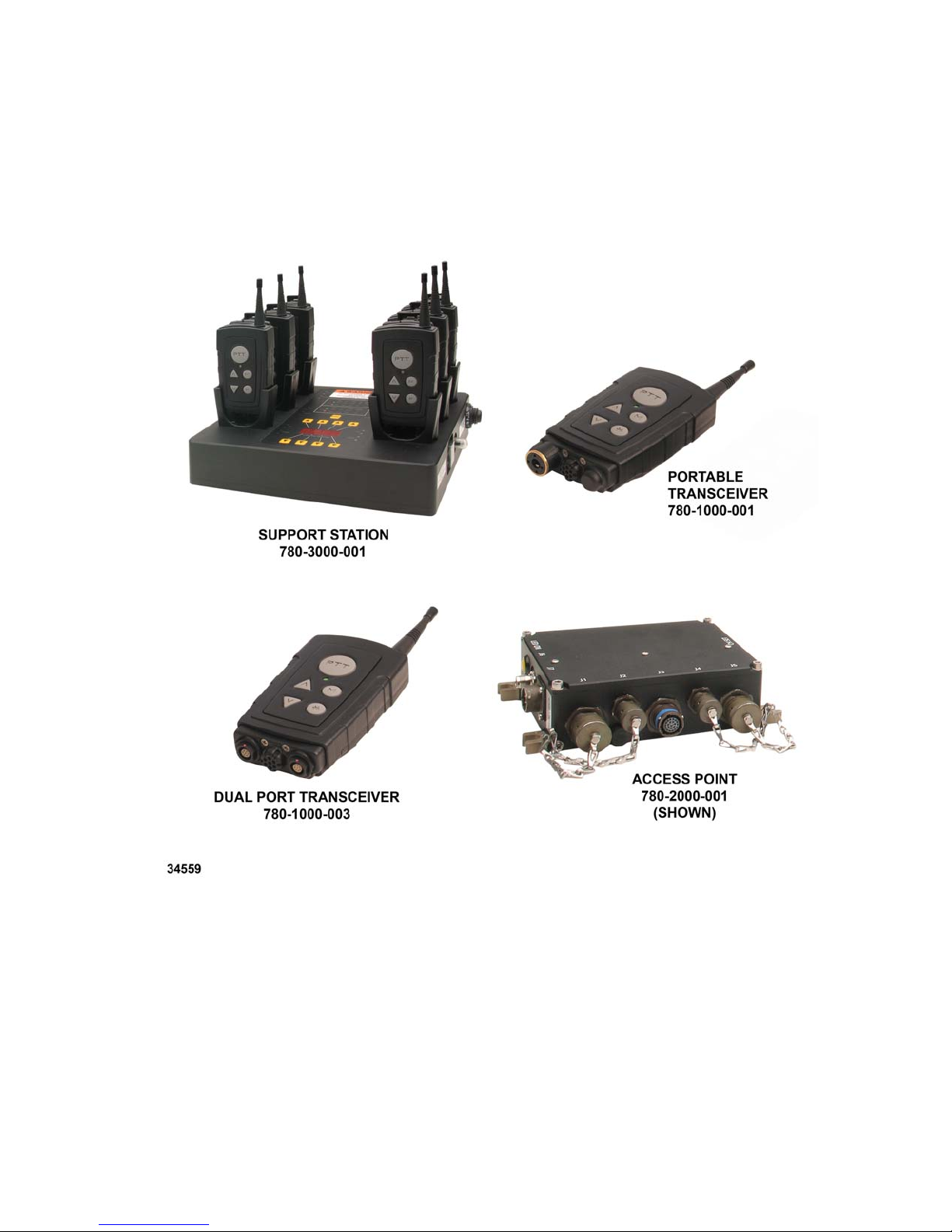
Figure 1.6-1. TruLink Components..........................................................................................1-4
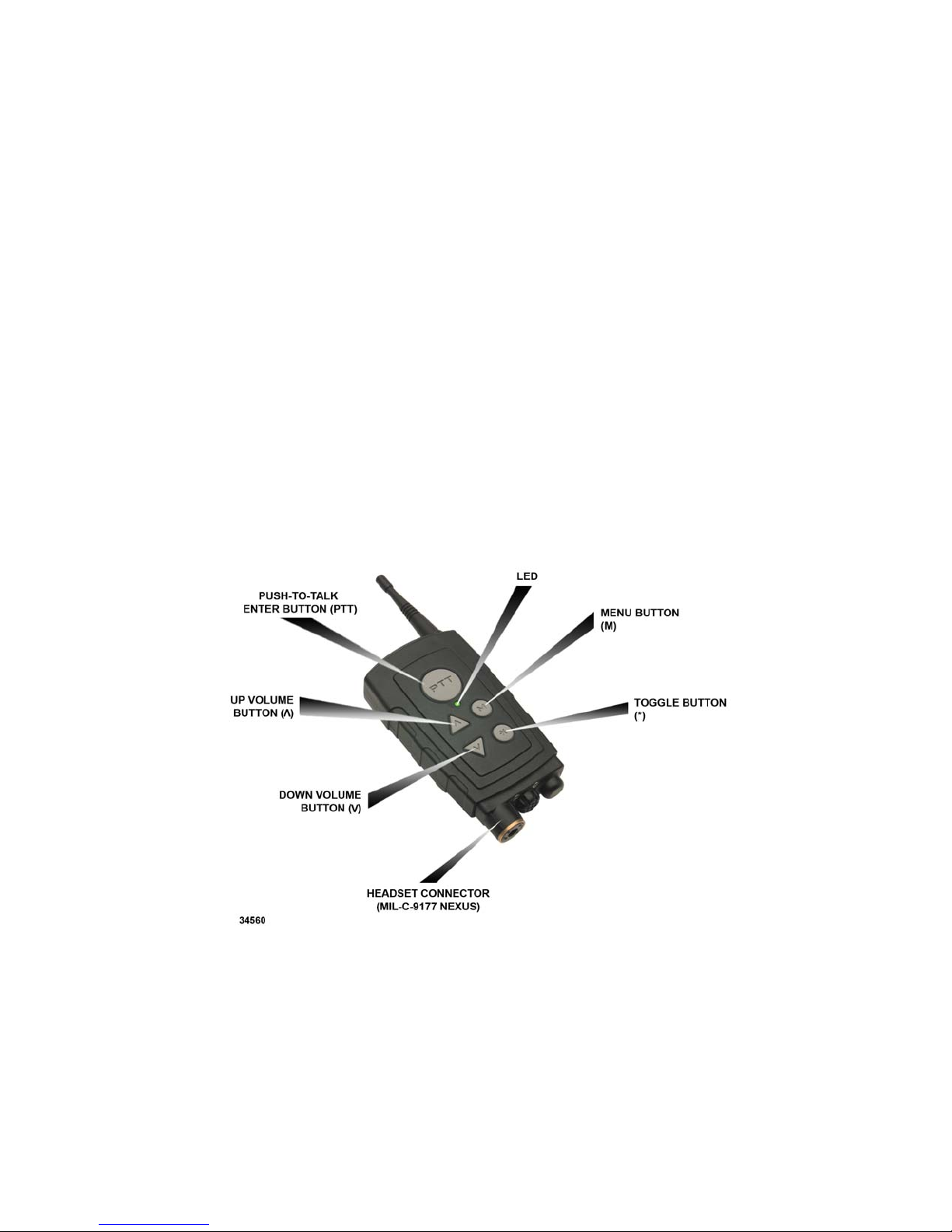
Figure 2.3.2-1. TruLink Portable Transceiver (TPT)..................................................................2-2
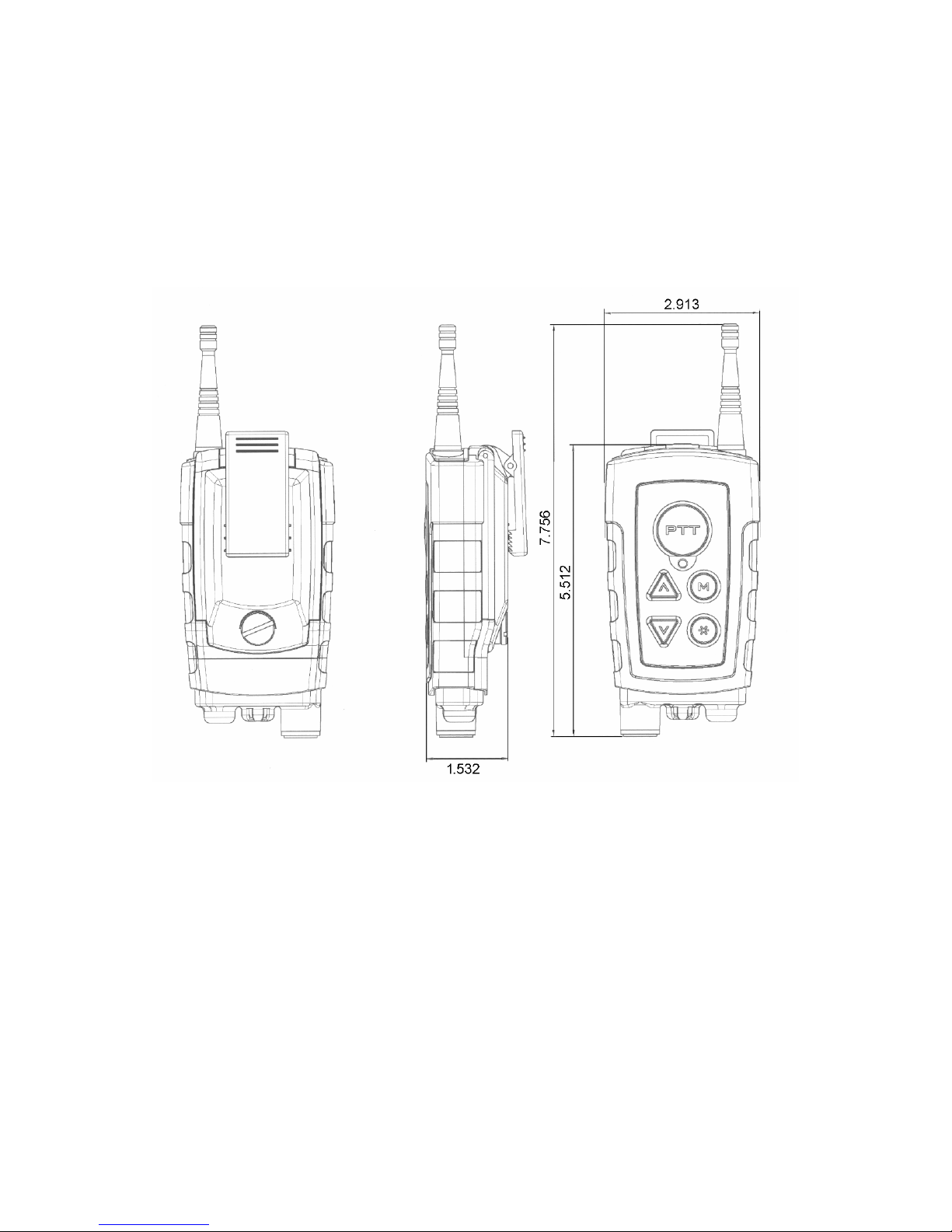
Figure 2.3.4-1. TPT Unit Dimensions (Inches)...........................................................................2-4
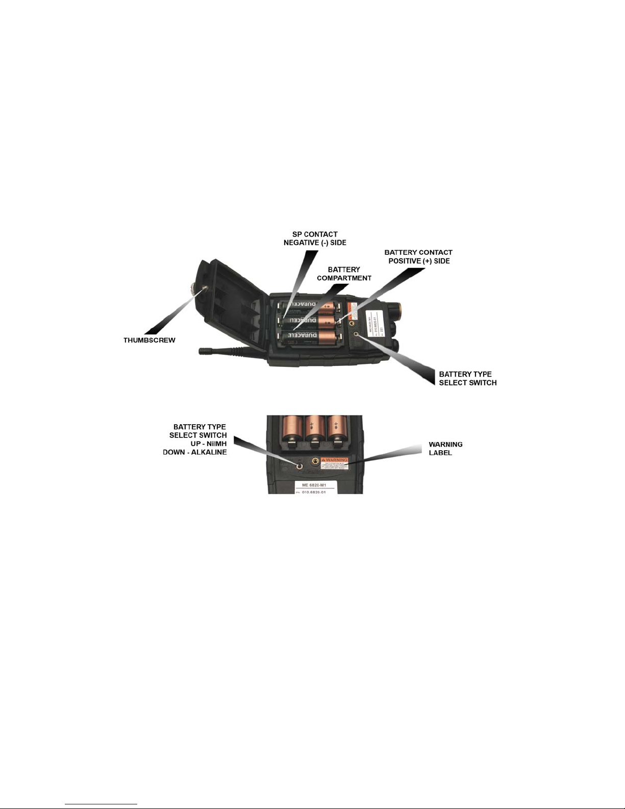
Figure 2.3.4-2. Battery Installation..............................................................................................2-5
Figure 3.1-1. TPT and TAP Network.......................................................................................3-1
Figure 3.3.1-1. TAP Unit Dimensions (Inches)...........................................................................3-2
Figure 3.1.1-2. TAP Controls and Connectors............................................................................3-3
Figure 4.1-1. Dual Port Transceiver.........................................................................................4-1
Figure 4.2-1. Dual Port Transceiver (DPT) Unit Dimensions..................................................4-2
Figure 5.2-1. TSS Controls and Indicator.................................................................................5-1
Figure 5.2-2. TSS Display Overlay..........................................................................................5-2
LIST OF TABLES
TITLE
Table 1.6.1 TruLink Equipment List .....................................................................................1-3
Table 2.6.1-1 LED Indications..................................................................................................2-7
Table 2.6.2-1 Audio Indications................................................................................................2-9
Table 2.3.6-1 Summary of Available SynVoice Phrases (Configuration-Dependant)............2-10
Table 3.4.6-1 Status LED Indications.......................................................................................3-6
Table 5.3-1 Charge LED Indication.......................................................................................5-3
Table 5.4-1 BIT LED Indications ..........................................................................................5-3
PAGE
TM1150007 REV A (04/07) v
USE OR DISCLOSURE OF DATA CONTAINED ON TH IS PAGE IS SUBJECT TO THE
RESTRICTION ON THE TITLE PAGE OF THIS DOCUMENT.
Page 9

T ELEPHONICS C ORPORATION
C
OMMUNICATION S YSTEMS D IVISION
CHAPTER 1
GENERAL
1.1 INTRODUCTION
®
This document will introduce the operator to the many features and capabilities of TruLink
Intercommunication System. It will provide the operator with the instructions necessary for the
proper handling and operation of TruLink and its component parts, and basic instructions for
maintaining the TruLink in proper working order.
1.2 DEFINITIONS AND ABBREVIATIONS
1.2.1 Definitions of Terms Used
The definitions of terms used in this document are as follows:
Wireless
Channel A collection of specific frequencies that define the RF link.
Network A collection of slaves and one master that form the communication group.
Sidetone User’s own audio heard in the user’s ear.
1.2.2 Abbreviations and Acronyms
Abbreviations and acronyms used in this document are listed below:
BIT Built-in Test
FHSS Frequency Hop Spread Spectrum
LPD Low Probability Detection
LPI Low Probability Intercept
mAh milli-Ampere hour
NiMH Nickel Metal Hydride
NVG Night Vision Goggles
PTT Push-To-Talk
SynVoice Synthetic Voice (recorded voice messages)
TAP TruLink Access Point Transceiver
TPT TruLink Portable Transceiver
TM115007 REV A (04/07) 1-1
USE OR DISCLOSURE OF DATA CONTAINED ON TH IS PAGE IS SUBJECT TO THE
RESTRICTION ON THE TITLE PAGE OF THIS DOCUMENT.
Page 10

T ELEPHONICS C ORPORATION
C
OMMUNICATION S YSTEMS D IVISION
TSS TruLink Support Station
DPT TruLink Dual Port Transceiver
VOX Voice Operated Keying
1.3 TRULINK DESCRIPTION
TruLink is a versatile wireless system in that it operates in various situations and environments. In
scenarios where portable intercom functionality is needed, only TruLink Portable Transceivers
(TPTs) are required.
The TruLink system is a fully duplex system that permits multiple users to speak simultaneously.
Unlike conventional walkie-talkies, TruLink users can converse among themselves without pressing
a Push to Talk button or waiting for another user to finish their transmission.
The system supports 50 channels (0-49). Depending on the system configuration, up to 31 users can
be logged on to a channel. Each channel is an independent network. A TruLink network is composed
of one TruLink unit designated as the master and all other TruLink units operating as slaves.
The TruLink Support Station (TSS) is also available with the ability to charge commercially
available NiMH batteries while still in a TPT unit, display built-in test (BIT) results, and set the
channel on up to six TPTs at a time.
Table 1.6-1 provides a list of the TruLink equipment and part numbers, embedded within the TPT,
TAP and DTP part number is a specified configuration which is factory loaded in the unit, i.e., 7801000-001-CF00xx-Mx, where the CF00xx-Mx is configuration specific. Please see specific
configuration addendums for details on the individual configurations.
A picture of each of the units in the TruLink system is shown in Figure 1.6-1.
1.4 NETWORK CONFIGURATION
A TruLink network is composed of one master unit and a group of slave units. The master unit is the
central point of the TruLink network. All slave-to-slave communications are routed through the
master. When a network includes a TAP or a DPT, it is typically designated the network master.
However, any TPT can be set to be the master.
1.5 CAPABILITIES
TruLink uses a modulation technique, Frequency Hop Spread Spectrum (FHSS), which provides
security improvements for Low Probability Intercept (LPI) and Low Probability Detection (LPD),
over conventional narrow-band radios that are susceptible to intercept by low-tech scanners. The
technique also provides some resistance to interference caused by undesired signals and multipath.
TruLink’s rugged construction is built to withstand extreme environments of: temperatures, sand,
dust and moisture. Rugged environments also involve high noise and poor RF conditions. TruLink
uses advanced Digital Signal Processing (DSP) technology to mitigate these effects.
TM115007 REV A (04/07) 1-2
USE OR DISCLOSURE OF DATA CONTAINED ON TH IS PAGE IS SUBJECT TO THE
RESTRICTION ON THE TITLE PAGE OF THIS DOCUMENT.
Page 11

T ELEPHONICS C ORPORATION
C
OMMUNICATION S YSTEMS D IVISION
1.6 TRULINK EQUIPMENT
The TruLink system can be composed of the following equipment:
Table 1.6.1
TruLink Equipment List
NAME PART NUMBER COMMENT
TruLink Access Point
(TAP)
TruLink Portable
Transceiver (TPT)
TruLink Dual Port
Transceiver (DPT)
TruLink Support Station
(TSS)
780-2000-001-CF00xx-Mx780-2000-002CF00xx-Mx (equipped with dust caps for
the connectors)
Typically employed to connect the
TruLink System to radios or wired
intercom systems
780-1000-001-CF00xx-Mx Handheld wireless unit
780-1000-003-CF00xx-Mx Handheld wireless unit which is
typically used to interface TruLink to
wired intercom systems
(TSS) 780-3000-001 Recharges NiMH batteries in the TPT
TM115007 REV A (04/07) 1-3
USE OR DISCLOSURE OF DATA CONTAINED ON TH IS PAGE IS SUBJECT TO THE
RESTRICTION ON THE TITLE PAGE OF THIS DOCUMENT.
Page 12
T ELEPHONICS C ORPORATION
C
OMMUNICATION S YSTEMS D IVISION
TM115007 REV A (04/07) 1-4
USE OR DISCLOSURE OF DATA CONTAINED ON TH IS PAGE IS SUBJECT TO THE
Figure 1.6-1. TruLink Components
RESTRICTION ON THE TITLE PAGE OF THIS DOCUMENT.
Page 13

T ELEPHONICS C ORPORATION
C
OMMUNICATION S YSTEMS D IVISION
CHAPTER 2
OPERATION
2.1 OVERVIEW
The TPT is the portable unit in the TruLink wireless communication system. The operator wears the
TPT along with a headset that includes headphones and a microphone. The TPT has an operator
interface consisting of buttons for input and an audio voice menu, known as SynVoice, for output.
The operator interface consists of five keys, a two-colored LED and an audio voice menu, SynVoice.
The SynVoice is a sampled phrase database that is used as an audio display, instead of a visible
display, to indicate selections and status.
Key presses in response to a voice menu modify the operation of the TPT.
The keys on the TPT unit are: PTT, M, up arrow, down arrow, and *. For every key pressed, a KEY
CLICK sound is heard in the headset.
2.2 PHYSICAL DESCRIPTION
The TPT is a handheld device as shown in Figure 2.3.2-1. The key elements of the unit are the
keypad, antenna and headset jack, powered by three AA batteries.
The keypad is ergonomically designed to facilitate use with gloves. The antenna is designed to be
flexible and durable. The headset jack is strategically located on the bottom to allow the headset cord
to drape naturally.
It measures approximately 7.75 inches high (with antenna) by 2.9 inches wide by 1.9 inches in depth
(with belt clip). See Figures 2.3.4-1 and -2. The TPT weighs approximately 11 oz. (without
batteries).
2.3 BATTERIES
2.3.1 Installing/Changing
The battery compartment is located under the hinged cover on the back of the TPT unit (see Figure
2.3.2-1). To access the batteries, rotate the thumbscrew counterclockwise until disengaged and raise
the cover. Remove the depleted batteries and install fresh batteries with the positive end down.
CAUTION
Battery type switch must be properly set to
TM115007 REV A (04/07) 2-1
USE OR DISCLOSURE OF DATA CONTAINED ON TH IS PAGE IS SUBJECT TO THE
avoid damaging the TPT unit.
RESTRICTION ON THE TITLE PAGE OF THIS DOCUMENT.
Page 14
T ELEPHONICS C ORPORATION
C
OMMUNICATION S YSTEMS D IVISION
Set the battery type switch to match the battery installed (up for NiMH or down for alkaline). Close
the cover and rotate the thumbscrew clockwise till finger tight. Do not over tighten screw to avoid
damaging the battery compartment.
Note
NiMH batteries must be fully charged before
using the TPT. Batteries can be installed in a
TPT and then placed in the TSS for charging, or
fully charged in an external battery charger
before installing in a TPT.
2.3.2 Battery Type
The TPT uses three AA batteries. Either NiMH or alkaline cells may be used. NiMH batteries must
be rated at greater than 1800 mAh.
Note
Batteries are not included in the purchase of the
TPT or DTP.
TM115007 REV A (04/07) 2-2
USE OR DISCLOSURE OF DATA CONTAINED ON TH IS PAGE IS SUBJECT TO THE
Figure 2.3.2-1. TruLink Portable Transceiver (TPT)
RESTRICTION ON THE TITLE PAGE OF THIS DOCUMENT.
Page 15

T ELEPHONICS C ORPORATION
C
OMMUNICATION S YSTEMS D IVISION
TPT BUTTON FUNCTION
∧ and ∨ (held
simultaneously)
∧
∨
M
¼
PTT
Power On/Off
Volume Up
Volume Down
Menu, scrolls through Menu Options
Toggle, toggles through Menu Sub-Options
Push-To-Talk/Enter, use as a Push-To-Talk button
and to enter/confirm Menu selections.
2.3.3 Low Battery Warning
The TPT is designed to operate for approximately 8 hours on a fresh set of batteries. After
approximately 7½ hours, the operator will get two battery indications; an audible “BATTERY
LOW” SynVoice warning through the headset, and a blinking red LED, BATTERY LOW, on the
front of the unit. After 20 minutes of additional use, the SynVoice will announce “BATTERY
EMPTY” through the headset. Shortly thereafter the TPT will automatically turn off.
2.3.4 Charging the TPT
When the low battery warning sounds, the operator may either install a fresh set of batteries or
recharge them. Alkaline batteries must be replaced for continued use. NiMH batteries can be
recharged while still in the TPT unit. Simply place the unit into an open holder on the TSS and
power the TSS up. As the batteries are charging, the LED will blink with an alternate red/green
color. The LED will illuminate with a steady green light when the batteries are fully charged.
Note
NiMH batteries must be recharged within 8
hours of “Battery Empty” or automatic
shutdown. Failure to do so may render batteries
unable to be charged in the Support Station.
See Figures 2.3.4-1 and 2.3.4-2 for unit dimensions and additional battery installation information.
TM115007 REV A (04/07) 2-3
USE OR DISCLOSURE OF DATA CONTAINED ON TH IS PAGE IS SUBJECT TO THE
RESTRICTION ON THE TITLE PAGE OF THIS DOCUMENT.
Page 16
T ELEPHONICS C ORPORATION
C
OMMUNICATION S YSTEMS D IVISION
TM115007 REV A (04/07) 2-4
USE OR DISCLOSURE OF DATA CONTAINED ON TH IS PAGE IS SUBJECT TO THE
Figure 2.3.4-1. TPT Unit Dimensions (Inches)
RESTRICTION ON THE TITLE PAGE OF THIS DOCUMENT.
Page 17
T ELEPHONICS C ORPORATION
C
OMMUNICATION S YSTEMS D IVISION
TM115007 REV A (04/07) 2-5
USE OR DISCLOSURE OF DATA CONTAINED ON TH IS PAGE IS SUBJECT TO THE
Figure 2.3.4-2. Battery Installation
RESTRICTION ON THE TITLE PAGE OF THIS DOCUMENT.
Page 18

T ELEPHONICS C ORPORATION
C
OMMUNICATION S YSTEMS D IVISION
2.4 ANTENNA
The TPT antenna is designed with a flexible tip for rugged use. It is also designed for easy
replacement. Simply rotate the antenna counterclockwise to remove. Place a new antenna over the
connector and rotate clockwise to install.
2.5 HEADSET
The TPT can be configured in the factory to use a number of standard headsets. Consult the
appropriate configuration addendum for the default headset setting.
2.6 TPT STATUS AND INDICATORS
The unit’s status and operation are indicated visually via LEDs, and audibly via tone and SynVoice.
The operator should become familiar with the visual and audible indicators before powering up a
TPT unit.
2.6.1 Visual Indicators
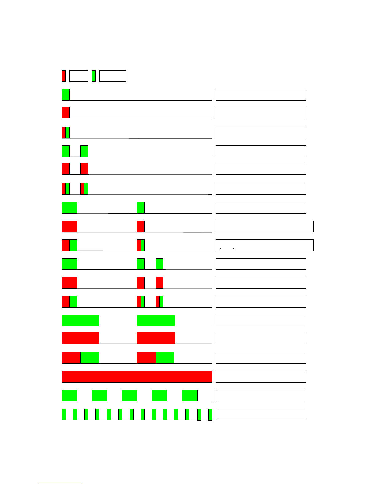
The TPT provides a two-color LED to signal various indications to the operator. Table 2.6-1
provides a summary of the LED indications.
TM115007 REV A (04/07) 2-6
USE OR DISCLOSURE OF DATA CONTAINED ON TH IS PAGE IS SUBJECT TO THE
RESTRICTION ON THE TITLE PAGE OF THIS DOCUMENT.
Page 19

T ELEPHONICS C ORPORATION
C
OMMUNICATION S YSTEMS D IVISION
Table 2.6.1-1
LED Indications
STATUS COLOR ON TIME (MS) OFF TIME (MS)
BATT OK, Slave logged on to network GREEN 100 1900
LOW BATT, Slave logged on to network RED 100 1900
CHARGE BATT, Slave logged on to network RED-GREEN 50 + 50 1900
NORMAL, Master logged on to network GREEN 100/100 150/1650
LOW BATT, Master logged on to network RED 100/100 150/1650
CHARGE BATT, logged on to network RED-GREEN 50 + 50/50 + 50 150/1650
CONNECTED BATT OK, Slave connected to
GREEN 200/100 800/900
platform
CONNECTED LOW BATT, Slave connected and
RED 200/100 800/900
low battery
CONNECTED CHARGE, Slave connected and
RED-GREEN 100 + 100/50 + 50 800/900
charging battery
CONNECTED BATT OK, Master connected to
GREEN 200/100/100 800/150/650
platform
CONNECTED LOW BATT, Master connected
RED 200/100/100 800/150/650
and low battery
CONNECTED CHARGE, Master connected and
charging battery
RED-GREEN 100 + 100/50 +
50/50 + 50
800/150/650
OUT OF RANGE, normal battery GREEN 500 500
OUT OF RANGE, low battery RED 500 500
OUT OF RANGE, charging battery RED-GREEN 250 + 250 500
POWER UP BOOT RED 1000 0
POWER UP RED 1000 0
MALFUNCTION (BIT failure, fatal error) RED 1000 0
SW DOWNLOAD READY GREEN 200 200
SW DOWNLOAD IN PROGRESS GREEN 10 100
TM115007 REV A (04/07) 2-7
USE OR DISCLOSURE OF DATA CONTAINED ON TH IS PAGE IS SUBJECT TO THE
RESTRICTION ON THE TITLE PAGE OF THIS DOCUMENT.
Page 20
T ELEPHONICS C ORPORATION
C
OMMUNICATION S YSTEMS D IVISION
Table 2.6.1-1
LED Indications (Continued)
Red Green
Batt OK, Slave logged on to network
Batt LOW, Slave logged on to network
Batt CHARGING, Slave logged on to
Batt OK, Master
Batt LOW, Master
Batt CHARGING, Master
Batt OK, CONNECTED Slave logged
Batt LOW, CONNECTED Slave logged
Batt CHARGING, CONNECTED Slave
Batt OK, CONNECTED Master
Batt LOW, CONNECTED Master
Batt CHARGING, CONNECTED
Batt OK, Out of Range
Batt LOW, Out of Range
Batt CHARGING, Out of Range
POWER_UP or MALFUNCTION
TM115007 REV A (04/07) 2-8
USE OR DISCLOSURE OF DATA CONTAINED ON TH IS PAGE IS SUBJECT TO THE
SW DOWNLOAD READY
SW_DOWNLOADING
RESTRICTION ON THE TITLE PAGE OF THIS DOCUMENT.
Page 21
T ELEPHONICS C ORPORATION
C
OMMUNICATION S YSTEMS D IVISION
2.6.2 Audible Indicators
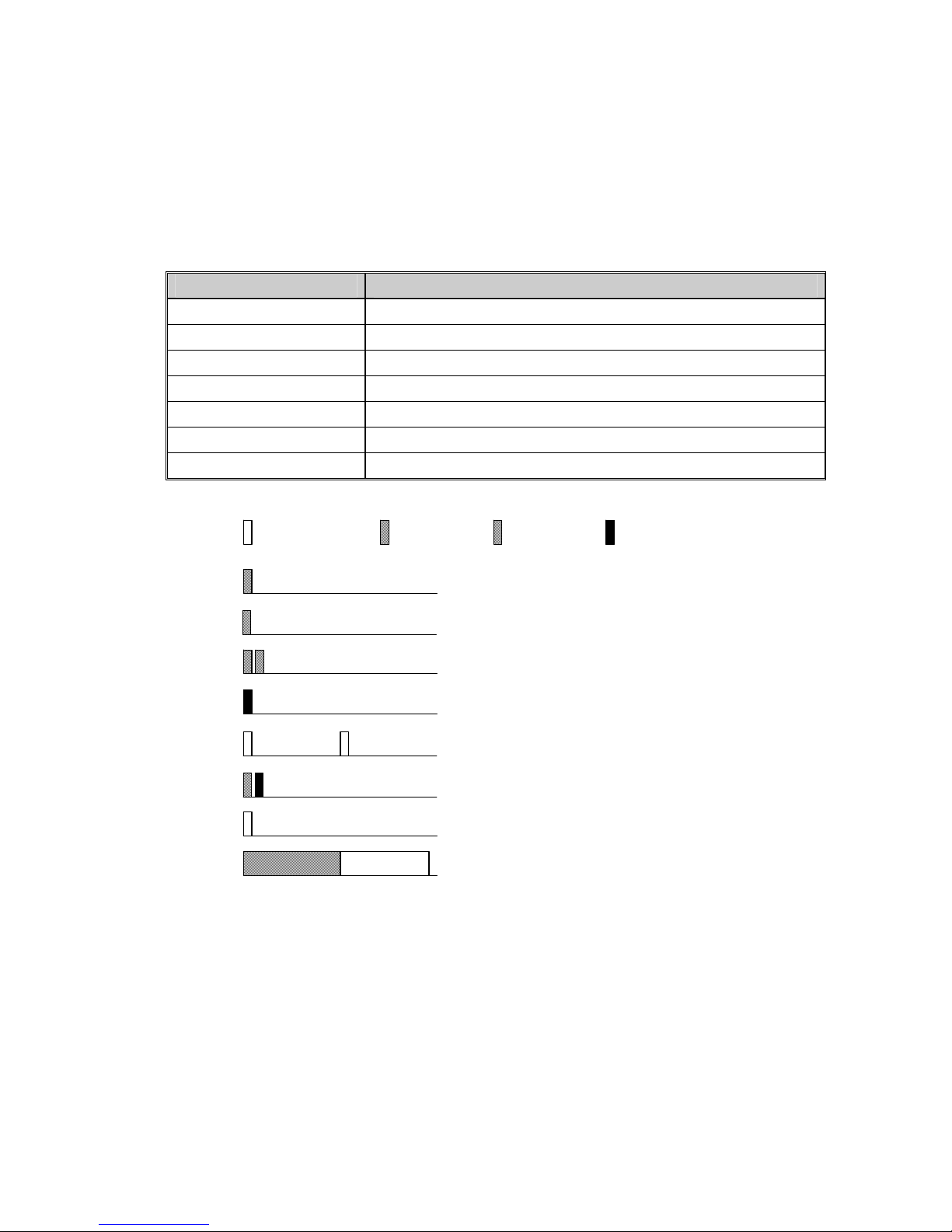
The TPT sends a number of different tones to the operator headset. Table 2.6.2-1 provides a listing
of these tones and their meanings.
Table 2.6.2-1
Audio Indications
SOUNDS EXPLANATION
KEY CLICK LOW A special warning key click at min volume
KEY CLICK Short tone sound for every key press
LONG KEY CLICK Tone for 10 channel step
KEY CLICK HIGH A special warning key click at max volume
NO SERVICE No net selected or available
EXIT Exit from any mode to default mode
NEG RESPONSE Connection reject, undefined operation, no network available
Lowest tone Low tone Mid tone High tone
2.6.3 SynVoice Phrases
KEY CLICK LOW
KEY CLICK
LONG KEY CLICK
KEY CLICK HIGH
NO SERVICE, repeated
AUTO CONFIRM
EXIT
NEG RESPONSE
The operator may be advised of status or configuration by verbal audio phrases called SynVoice.
Table 2.3.6-1 provides a listing of the available SynVoice phrases and their meanings. The actual
phrases heard by a TPT user will vary depending on the installed configuration.
TM115007 REV A (04/07) 2-9
USE OR DISCLOSURE OF DATA CONTAINED ON TH IS PAGE IS SUBJECT TO THE
RESTRICTION ON THE TITLE PAGE OF THIS DOCUMENT.
Page 22

T ELEPHONICS C ORPORATION
C
OMMUNICATION S YSTEMS D IVISION
Table 2.3.6-1
Summary of Available SynVoice Phrases (Configuration-Dependant)
PHRASE
NO.
SynVoice PHRASE COMMENT
1 CHANNEL ZERO
… …
50 CHANNEL FORTY NINE
71 MASTER
72 SLAVE
73 EXTERNAL AVAILABLE The destination mode is now available in the menu.
74 DESTINATION NORMAL
81 LED NORMAL
82 LED HIGH LED setting for intense sunshine.
83 LED NVG
84 LED TIME LED will be turned off after a configurable time.
85 LED OFF
89 LOGGED ON Successfully logged on or started a network.
90 CONFIGURATION ERROR The unit has a different system configuration then the master of
the network. The unit will not be able to log on to this master.
91 VOX OFF
92 VOX ON
93 KEY LOCK OFF
94 KEY LOCK ON
103 ORDER CHANGE MASTER
104 ORDER SYNCHRONIZE AP
105 FAST KEY M OFF Normal mode.
106 FAST KEY M ON Monitor mode.
107 LOW BATTERY WARNING 1 First battery warning level reached
108 LOW BATTERY WARNING 2 Second battery warning level reached
133 ORDER CHANGE MASTER
Order maker is informed that all units did not answer to the order.
LOST
134 ORDER CHANGE MASTER OK Order maker is informed that all units have answered to the order.
135 ORDERED CHANGE MASTER Unit is informed that another unit, the order maker, will take over
as master of the network.
136 ORDER SYNCHRONIZE AP
Order maker is informed that all units did not answer to the order.
LOST
137 ORDER SYNCHRONIZE AP OK Order maker is informed that all units have answered to the order.
138 ORDERED SYNCHRONIZE AP Unit is informed that an AP will try to take over as master of the
network.
TM115007 REV A (04/07) 2-10
USE OR DISCLOSURE OF DATA CONTAINED ON TH IS PAGE IS SUBJECT TO THE
RESTRICTION ON THE TITLE PAGE OF THIS DOCUMENT.
Page 23

T ELEPHONICS C ORPORATION
C
OMMUNICATION S YSTEMS D IVISION
2.7 TPT OPERATION
The TruLink network is designed to operate with one unit functioning as a MASTER and all other
units as SLAVES. The MASTER broadcasts received audio from one slave TPT to all other SLAVE
TPTs on the wireless network, as well as the wired ICS. If no TAP or DPT is in the network, then
one TPT must be set to act as the MASTER. The following paragraphs describe the TPT operation
without a TAP in the network. For operation with a TAP, see Section 4.
2.7.1 Introduction to TPT Man-Machine Interface
The user interacts with the TPT through the keypad and headset audio. The keypad accepts input
from the user. The TPT advises the user with audio as either tones or pre-recorded voice (SynVoice)
through the headset.
In general, the user initiates a command by pressing the M key. This starts an audio menu. By
repeatedly pressing the M key, the TPT will respond with the next menu item. Upon reaching the
desired item, the * key is used to cycle through the options (settings) available for the menu item.
When the user has reached the desired setting, the PTT key is pressed to establish and confirm the
setting.
2.7.2 Power ON/OFF
Note
If a TPT unit is turned on and does not log on to
a net, the TPT is designed to turn itself off after
two minutes to conserve battery life.
The operator should connect their headset and
position their microphone directly in front of
their mouth.
To switch the power on or off, the up and down arrow keys (i and j) are used together. Press and
hold both buttons for about 1 second until the LED illuminates green. When the unit has been
powered, the operator can start a network or automatically logon to an existing network.
2.7.3 Start-Up
When a TPT unit is powered on the operator will hear a SynVoice announcement “Channel xx,
Slave” or “Channel xx, Master” indicating the current channel setting and whether the TPT unit is set
to master or slave. Pressing the menu button “M” will cycle through the SynVoice start-up menu
options, which are:
“Channel xx”
“Master/Slave”
“Order Synchronize Access Point”
TM115007 REV A (04/07) 2-11
USE OR DISCLOSURE OF DATA CONTAINED ON TH IS PAGE IS SUBJECT TO THE
RESTRICTION ON THE TITLE PAGE OF THIS DOCUMENT.
Page 24

T ELEPHONICS C ORPORATION
C
OMMUNICATION S YSTEMS D IVISION
These are the only options available until the TPT is part of a TruLink network.
2.7.3.1 Starting a Network
When not located near the MASTER TAP or DPT, a group of TPTs can set up a standalone network.
The operator most likely to remain in the workgroup should start-up their TPT first, and set it to
MASTER. Only one TPT should be set to MASTER for a given channel. ALL other TPTs on a
given channel should be set to SLAVE (default setting).
An operator can only switch a TPT between SLAVE and MASTER before the unit logs on to a
network. If a unit is logged on to a network, the operator must cycle power to access the proper
change menu.
If the PTT button is not pressed within a few seconds of making a change, the new setting is aborted
and no changes are made.
To change to MASTER: Press the menu (M) button until “Slave” is announced. Press the toggle
button (*) until “Master” is announced then immediately press the enter button (PTT) to accept the
change.
If the TPT unit is set to MASTER, it will logon to the network (which is itself) automatically after a
few seconds or after the operator presses the enter button (PTT). The operator will hear a voice
announcement “Logon OK”.
2.7.3.2 Logging On to a Network
When logging on to an existing network, a TPT unit must be set to SLAVE.
A SLAVE will only announce, “Logon OK”, if it finds and logs on to a MASTER on the same
channel.
To logon to an existing network: turn ON the TPT, set it to SLAVE (if needed), set it to the proper
channel, and wait for it to automatically logon to the network. The operator will hear a voice
announcement “Logon OK”.
Note
To change a TPT to a SLAVE: Press the menu
(M) button until “Master” is announced. Press
the toggle button (*) until “Slave” is announced
then immediately press the enter button (PTT) to
accept the change.
If no network is available a “NEG RESPONSE” tone is heard, followed by a “NO SERVICE” tone
which is repeated until the next logon try.
TM115007 REV A (04/07) 2-12
USE OR DISCLOSURE OF DATA CONTAINED ON TH IS PAGE IS SUBJECT TO THE
RESTRICTION ON THE TITLE PAGE OF THIS DOCUMENT.
Page 25

T ELEPHONICS C ORPORATION
C
OMMUNICATION S YSTEMS D IVISION
If logon fails due to a mismatch of system configuration, the operator will hear a SynVoice message
“CONFIGURATION ERROR” in the headset. This is followed by a “NO SERVICE” tone, which is
repeated until next logon try.
The unit tries to logon for approximately two minutes. If unsuccessful, the user is notified by
SynVoice “AUTO POWER OFF” and the power is automatically turned off. The operator can
access the start-up menu and change channels until either the unit successfully logs on to the network
or it powers down.
2.8 SETTINGS
When the unit has logged on to a network, the operator typically has access to the following settings
with consecutive presses of the M key:
CHANNEL [channel list]
VOX [on/off]
KEY LOCK [on/off]
LED [normal, NVG, high, time, or off]
ORDER CHANGE MASTER
ORDER SYNCHRONIZE ACCESS POINT
The actual SynVoice menu a user hears is dependant on the configuration installed in the TPT (or
DPT). Some configurations do not have all these messages, others include more SynVoice messages.
Consult the appropriate configuration addendum for details. The M key is used for cycling between
the available menu selections.
The * is used for changing the settings of the selected item. When a setting has been changed, PTT is
used for confirming the new setting.
If the settings menu has been accessed and no further action is taken, after a few seconds the unit
exits the menu and the operator will hear a “MENU EXIT” tone in his headset.
2.8.1.1 CHANNEL Setting for TPT
Changing the channel when the unit is MASTER of the network is not recommended since the action
will disconnect all logged on operators.
To change the channel:
Press and release the M button until the SynVoice announces the CHANNEL setting, e.g.,
“CHANNEL ONE”.
Press and release * to step through the channel list. If * is held down for more than 0.5
seconds a “LONG KEY CLICK” will be heard instead of the ordinary key click. One long
key click corresponds to ten steps in the channel list. When * is released a SynVoice
message informs the operator of the selected setting, e.g., “CHANNEL ONE”. If the selected
channel is not the desired channel, press * again.
TM115007 REV A (04/07) 2-13
USE OR DISCLOSURE OF DATA CONTAINED ON TH IS PAGE IS SUBJECT TO THE
RESTRICTION ON THE TITLE PAGE OF THIS DOCUMENT.
Page 26

T ELEPHONICS C ORPORATION
C
OMMUNICATION S YSTEMS D IVISION
To confirm the selected channel, press PTT. If the setting is not confirmed within a few
seconds of the change, the menu will be exited without any changes.
If the unit is a MASTER, it will automatically start a new network. If the unit is a SLAVE, it will
automatically try to find and logon to a network.
2.8.1.2 VOX Setting
The VOX setting, voice operated keying, can be toggled on or off.
Press and release the M button until the SynVoice announces the VOX setting, e.g. “VOX
ON”.
Press and release * to change setting between ON or OFF. When * is released a SynVoice
message informs the operator of the selected setting, e.g., “VOX OFF”. If the selected
setting is not the desired setting, press * again.
To confirm the selected channel, press PTT. If the setting is not confirmed within a few
seconds of the change, the menu will be exited without any changes.
2.8.1.3 KEY LOCK Setting
When KEY LOCK is enabled it protects against accidental key press. With key lock on, the operator
can send an Emergency PTT or exit the mode.
Press and release the M button until the SynVoice announces the KEY LOCK setting, i.e.,
“KEY LOCK OFF”.
Press and release * once to turn on key lock. When * is released a SYNVOICE message
informs the operator of the selected setting, e.g., “KEY LOCK ON”. If the selected setting is
not the desired one, press * again.
To confirm the selected channel press PTT. If the setting is not confirmed within a few
seconds of the change, the menu will be exited without any changes.
To exit the KEY LOCK mode:
Press and release the M button once. The SynVoice announces the KEY LOCK setting, i.e.,
“KEY LOCK ON”.
Press and release * once to turn off KEY LOCK. When * is pressed, KEY LOCK mode is
immediately exited and the SynVoice message informs the operator of the selected setting,
e.g., “KEY LOCK OFF”.
2.8.1.4 LED Setting
The LED has five available settings:
1. Normal – LED is visible to naked eye in ambient light (or darkness).
2. High – LED is brighter than normal.
3. NVG – LED is less visible to naked eye. Night vision goggles are required.
4. Time – LED only functions for a few seconds after power-up and then turns off.
TM115007 REV A (04/07) 2-14
USE OR DISCLOSURE OF DATA CONTAINED ON TH IS PAGE IS SUBJECT TO THE
RESTRICTION ON THE TITLE PAGE OF THIS DOCUMENT.
Page 27

T ELEPHONICS C ORPORATION
C
OMMUNICATION S YSTEMS D IVISION
5. Off – LED is always off. No visible status is available, including power. This setting is not
normally recommended.
The LED settings cycle through; “LED NORMAL”, “LED HIGH”, “LED NVG”, “LED TIME”, and
“LED OFF”.
Press and release the M button until the SynVoice announces the LED setting, e.g. “LED
NORMAL”.
Press * to cycle through the selection list of LED settings, one key click corresponds to one
step in the selection list. When * is released a SynVoice message informs the operator of the
selected setting, e.g., “LED NVG”. If the selected setting is not the desired one, press *
again.
To confirm the setting press PTT. If the setting is not confirmed within a few seconds of the
change, the menu will be exited without any changes.
2.8.1.5 ORDER CHANGE MASTER Setting
Changing the MASTER unit of the network will temporarily disconnect all logged on operators.
Order Change Master is used to switch the MASTER unit of a network. It swaps the roles of
MASTER and SLAVE between the issuing SLAVE and the current MASTER. This should only be
employed when TPTs are part of a standalone network (no TAP or DPT).
From the SLAVE unit, press and release the M button until the old SLAVE unit emits a
SynVoice message “ORDER CHANGE MASTER”.
Press and release PTT once to initiate the change setting. When PTT is released a SynVoice
message, “ORDER CHANGE MASTER OK”, confirms the change to the operator. At the
same time, everyone on the network is alerted to the impending change via the SynVoice
message “AUTO CHANGE MASTER”.
The new MASTER unit then begins a network logon procedure. The successful logon is
confirmed to the operator via the SynVoice message “LOGON OK”.
Within one minute all other units on the network, including the old MASTER unit that is now
a SLAVE, re-logon to the network of the new MASTER. The successful logon is confirmed
to the operator via the SynVoice message “LOGON OK”, and communication can then
continue as before.
2.8.1.6 ORDER SYNCHRONIZE ACCESS POINT Setting (Changing TAP Channel)
This setting is used only when there is a connected TAP MASTER unit in the network. For a
description of this setting, see Paragraph 4.4.
TM115007 REV A (04/07) 2-15
USE OR DISCLOSURE OF DATA CONTAINED ON TH IS PAGE IS SUBJECT TO THE
RESTRICTION ON THE TITLE PAGE OF THIS DOCUMENT.
Page 28

T ELEPHONICS C ORPORATION
C
OMMUNICATION S YSTEMS D IVISION
2.8.2 Talking on the Network
The user is offered three methods of speaking on the network.
With the first mode, the user breaks VOX by talking. The user knows VOX has been broken
when his sidetone is heard. Note that the TPT’s VOX setting must be in VOX ON for this
method to work.
With the second method, the user presses the PTT button. This method is useful if the VOX is
not enabled and in noisy environment when it may be hard to break VOX.
To make an emergency announcement on the net, the operator can press the PTT twice within
0.5 seconds. This will grant immediate access to a voice channel on the net.
It should be noted that the destination of the transmission is not dependent of the access method in
this configuration. However, the priority differs in between these access methods with VOX as the
lowest priority and emergency as the highest priority.
2.8.2.1 Transmission Rejection
When the operator wants to transmit and the network is full, a “NEG RESPONSE” sound is heard in
the operator headset. The operator can then try to use an access method with higher priority.
2.8.2.2 Transmission Indication
When the operator transmits successfully, a side tone is generated to the operator’s headset.
2.8.3 Volume Adjustment
The up and down arrow keys (i and jare used to adjust the volume. A “KEY CLICK” sound
indicates a change of volume level. The volume is never completely shut off. If the user tries to
decrease the volume lower then the minimum level, the “KEY CLICK LOW” sound is heard instead
of the normal key click.
If the user tries to increase the volume higher than the maximum level, the “KEY CLICK HIGH”
sound is heard instead of the normal key click. To increase the volume one more step higher, press
and hold the up arrow key (i) for three seconds. This will override the normal high setting to a
maximum level. At the same time a repeating warning signal is started to alert the user of the
overridden volume limit. If the down arrow key (j) is pressed the volume is reduced one level and
the volume is again set to the NORMAL limit.
2.8.4 Out of Range
If an operator takes a SLAVE TPT unit out of range and the radio connection with the MASTER is
lost, a “NO SERVICE” sound is heard in the headset. At the same time the LED indicates
OUT_OF_RANGE.
TM115007 REV A (04/07) 2-16
USE OR DISCLOSURE OF DATA CONTAINED ON TH IS PAGE IS SUBJECT TO THE
RESTRICTION ON THE TITLE PAGE OF THIS DOCUMENT.
Page 29

T ELEPHONICS C ORPORATION
C
OMMUNICATION S YSTEMS D IVISION
The SLAVE automatically tries to re-logon to the same MASTER. If successful the operator will be
notified with a SynVoice message “LOGON OK”. Otherwise the operator will hear a “NEG
RESPONSE” tone.
If the unit does not successfully logon to a network within approximately two minutes, the unit’s
power is automatically turned off. Before turning off the power the operator is notified with
SynVoice message “AUTO POWER OFF”.
2.8.5 Key-Click
Every key pressed generates a key-click sound to the headset.
2.8.6 Power-On BIT Failure
If any errors are encountered during the power-on BIT testing, the LED indicates MALFUNCTION.
If this occurs the unit requires servicing and should be taken out of service.
2.9 TPT CHECK OUT PROCEDURE
The following should be performed before using the unit(s):
Ensure that the unit uses fresh alkaline cells or newly charged NiMH cells.
Ensure that one unit is started as a master on an unused channel. Confirm that other TPTs, on
the same channel can successfully log on to the master.
TM115007 REV A (04/07) 2-17
USE OR DISCLOSURE OF DATA CONTAINED ON TH IS PAGE IS SUBJECT TO THE
RESTRICTION ON THE TITLE PAGE OF THIS DOCUMENT.
Page 30
T ELEPHONICS C ORPORATION
C
OMMUNICATION S YSTEMS D IVISION
CHAPTER 3
TRULINK ACCESS POINT
3.1 OVERVIEW
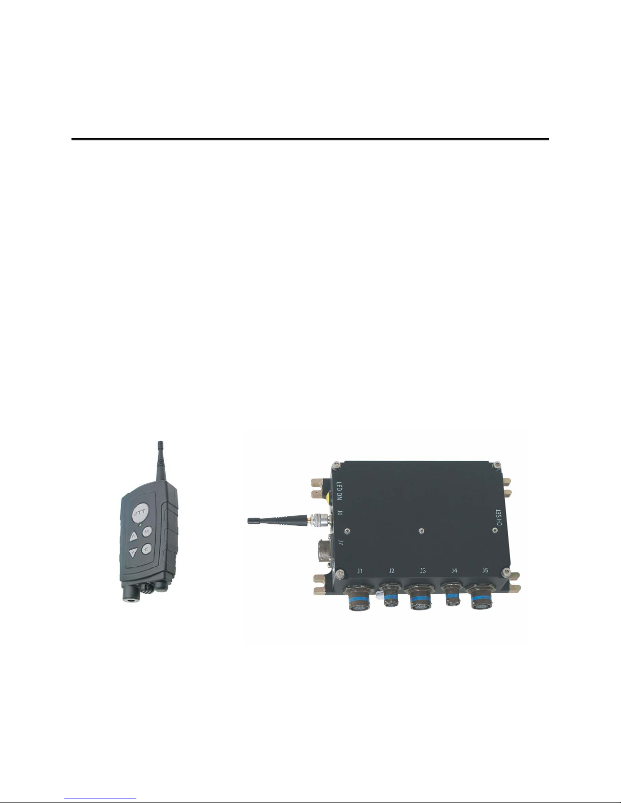
The TruLink Access Point (TAP) is used as either the long-range radio interface or as an interface to
a wired ICS. It is typically used for fixed installations. One TPT SLAVE and one TAP MASTER, as
shown in Figure 3.1-1, constitute a network. The TAP incorporates three audio ports and one data
port.
Radios are connected to the audio connectors of the TAP. The TAP provides the necessary audio and
keying connections needed to operate external radios. When used to interface to a wired intercom
system, one audio connector is employed.
The operation of the audio connectors is dependant on the configuration installed on the TAP.
The data port is only used for configuration installation.
Depending on configuration, up to 31 TPTs can be connected to the TAP with a maximum of up to
six TPTs transmitting simultaneously.
TM115007 REV A (04/07) 3-1
USE OR DISCLOSURE OF DATA CONTAINED ON TH IS PAGE IS SUBJECT TO THE
Figure 3.1-1. TPT and TAP Network
RESTRICTION ON THE TITLE PAGE OF THIS DOCUMENT.
Page 31
T ELEPHONICS C ORPORATION
C
OMMUNICATION S YSTEMS D IVISION
3.2 PHYSICAL DESCRIPTION
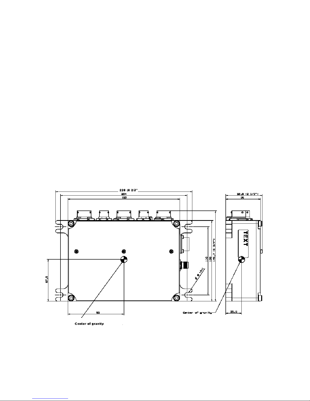
The TAP is powered by DC power from the host vehicle. It measures 8.7 inches in length by 5.7
inches wide by 2.3 inches high. It weighs approximately 2.9lbs. The physical characteristics are
shown in Figure 3.3.1-1.
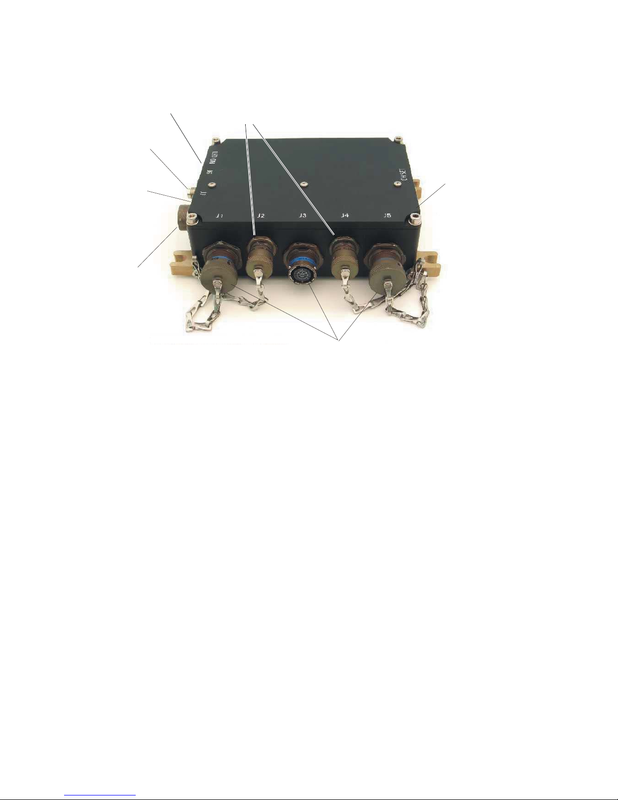
The TAP has connectors for power, antenna, audio and data. There are also two pushbuttons, one for
setting the channel and one to operate the status LED. See Figure 3.3.1-2 for a picture of the TAP
controls, indicator and connectors.
3.3 TAP INSTALLATION
3.3.1 Mounting
The TAP has four flanges for bolting the unit into the host vehicle. The flanges are bare metal to
facilitate connection to ground. The mounting surface should be cleaned to bare metal to ensure a
good chassis ground.
It is recommended that the TAP be located near the data and audio devices to avoid long lengths of
cabling. The unit also needs to be accessible by the operator for channel selection and to view the
LED status indicator.
TM115007 REV A (04/07) 3-2
USE OR DISCLOSURE OF DATA CONTAINED ON TH IS PAGE IS SUBJECT TO THE
Figure 3.3.1-1. TAP Unit Dimensions (Inches)
RESTRICTION ON THE TITLE PAGE OF THIS DOCUMENT.
Page 32
T ELEPHONICS C ORPORATION
(
A
A
C
OMMUNICATION S YSTEMS D IVISION
Power
Connector
LED
LED Button
(Not seen)
(Not Seen)
ntenna
Connector
Status
Status
LED
LE
(Not Seen)
(Not seen)
Data
Connectors
Data
Connectors
Channel Set
Button
Not seen)
udio
Connectors
Figure 3.1.1-2. TAP Controls and Connectors
3.3.2 Connections
3.3.2.1 Power Connector
The power connector is marked J7. The vehicle DC power source must be supplied through a 1 Amp
fuse or circuit breaker (not supplied).
3.3.2.2 Antenna Connector
The antenna connector is marked J6. The antenna connected to the TAP is chosen according to the
physical installation (vehicle, vessel or aircraft) and connects via a TNC-male with 50-Ohm
impedance. The standard antenna provided can be directly mounted to the TAP, or remotely
mounted not more than ten feet away via a cable (not supplied). The antenna must be located so that
there is a clear (RF) path between it and the users. The antenna cannot be located within a metal
enclosure.
3.3.2.3 Audio Connectors
The three audio connectors are marked J1, J3 and J5. The connectors are identical except that each is
keyed to mate with only one cable. Each connector has provisions for line level audio input and
output, both 600 Ohms. Additionally, a floating PTT discrete output is available. Both PTT wires
must be connected for proper operation. The low PTT line should be connected to the intercom
return.
TM115007 REV A (04/07) 3-3
USE OR DISCLOSURE OF DATA CONTAINED ON TH IS PAGE IS SUBJECT TO THE
RESTRICTION ON THE TITLE PAGE OF THIS DOCUMENT.
Page 33

T ELEPHONICS C ORPORATION
C
OMMUNICATION S YSTEMS D IVISION
The audio connectors may be connected to either long-range radios or to a wired ICS through a crew
station headset port. Up to three radios may be connected to the TAP.
When used to interface to a wired intercom system, one TAP audio connector is typically connected
to a headset port of a crew station.
The function of these connectors is dependant on the system’s configuration.
3.3.2.4 Data Connectors
The two data connectors are marked J2 and J4. Connector J2 is used to load and configure the TAP.
It is not a part of routine operation. Connector J4 is not used.
3.4 TAP OPERATION
A TAP is always operated as a MASTER. However, it requires a TPT SLAVE unit to change
channels.
3.4.1 Power ON/OFF
When power is applied to a host vehicle, a connected TAP unit is powered on automatically. The
TAP will always start-up as a MASTER unit on the channel it was previously set to when the vehicle
power was removed. If the channel is unknown, an operator can set the TAP channel using a TPT
SLAVE unit and the Order Synchronize Access Point setting described below. This setting can also
be used at any time during normal operation if it becomes necessary to change the network channel.
3.4.2 Echo Elimination Procedure
This procedure is employed when connecting a TAP to a wired ICS station. This procedure is
provided as a reference only. Due to electrical variations in different manufacturer’s products, the
procedure may need to be altered to achieve acceptable results.
When the TAP is configured for use with a wired intercom system, this procedure must be employed
to eliminate echo in the TruLink system caused by the wired ICS station’s sidetone.
The following procedure usually is required only during a wired system installation or replacement
of a wired system intercom station. However, it can be performed if there is a noticeable echo on a
TPT.
This procedure will eliminate echo on a TPT when a TAP is connected to a wired system.
Set wired system station to intercom selection.
Set wired system station to HOT MIC selection.
Set wired system station volume to approximately 50% setting.
Confirm that no headset is connected to the wired system crew station.
VOX sensitivity set to minimum (if present on crew station ICS)
TM115007 REV A (04/07) 3-4
USE OR DISCLOSURE OF DATA CONTAINED ON TH IS PAGE IS SUBJECT TO THE
RESTRICTION ON THE TITLE PAGE OF THIS DOCUMENT.
Page 34

T ELEPHONICS C ORPORATION
C
OMMUNICATION S YSTEMS D IVISION
Ensure all other stations are not transmitting on the intercom or have an open MIC. If no
headset is connected to a crew station, no action is required.
Ensure that the station is receiving no long-range radio audio.
Power up the wired system and the TAP.
On the TAP, press and hold the Channel SET and LED pushbuttons at the same time for five
seconds.
Power up a TPT and test for echo by speaking to the wired ICS.
If echo is heard, reduce the station’s volume control slightly until the echo is eliminated.
3.4.3 ORDER SYNCHRONIZE ACCESS POINT Setting (Change TAP Channels)
When a TAP is in the network, it is always the MASTER. Changing the channel of the MASTER
unit of the network will disconnect all logged on operators. All operators will have to change to the
new channel for their unit to be re-connected to the original network.
This setting allows a TPT unit the ability to change the channel of a TAP.
Notify all operators on the network that the channel is about to be changed.
Set the SLAVE unit to the channel desired for the TAP.
Press and release the M button until the SynVoice announces the “ORDER SYNCHRONIZE
ACCESS POINT” setting.
Press and release the * button on the TPT. The user will hear SynVoice announce “ORDER
SYNCHRONIZE ACCESS POINT”.
Press and hold the “SET CHANNEL” button on the TAP.
Press and release the PTT button on the TPT.
The SLAVE unit will initiate a re-logon to the new network channel of the MASTER. The
successful logon is confirmed to the operator via the SynVoice message “LOGON OK”, and
communication can then continue between operators on this channel.
For operation with groups of vehicles in close proximity, the TAP channels in groups of ten
should be avoided (for example: CH 1, CH11 and CH 21)
3.4.4 ORDER CHANGE MASTER Setting
CAUTION
The ORDER CHANGE MASTER setting
TM115007 REV A (04/07) 3-5
USE OR DISCLOSURE OF DATA CONTAINED ON TH IS PAGE IS SUBJECT TO THE
should not be used when a TAP is operating as
the MASTER in a network. It may be used
when a TPT is used as a MASTER.
RESTRICTION ON THE TITLE PAGE OF THIS DOCUMENT.
Page 35
T ELEPHONICS C ORPORATION
C
OMMUNICATION S YSTEMS D IVISION
ORDER CHANGE MASTER is used to switch out the MASTER unit of a network. It swaps the
roles of MASTER and SLAVE between the issuing SLAVE and the current MASTER. For further
information, see Paragraph 3.8.1.5.
3.4.5 Logging on to a Network
The TAP will always act as a MASTER. Therefore it will start a network at power-up and will
always succeed in the network logon. The TAP should be powered up before any TPTs are turned
on.
3.4.6 Status Indications
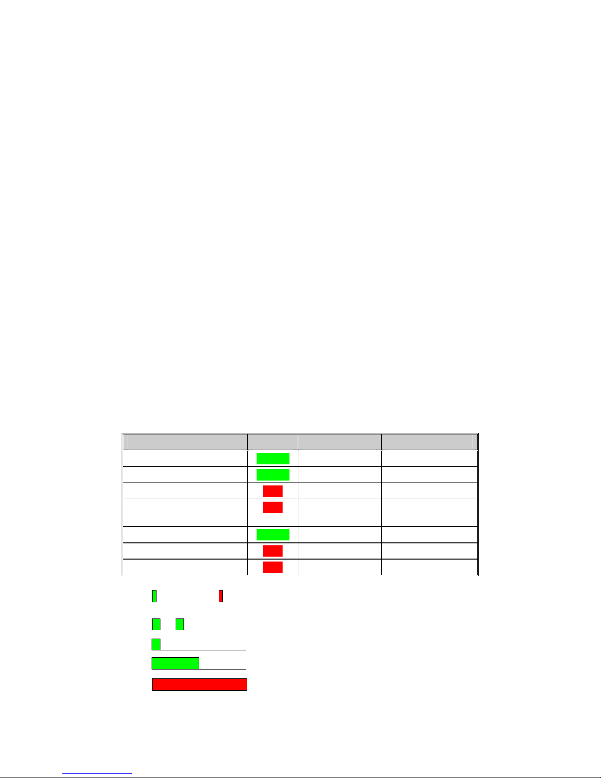
The TAP status and operation are indicated visually with a two-color LED on the side of the TAP
unit. Press and hold the LED button to view the status LED. See Table 3.4.6-1 for an explanation of
the status LED indications. If a TPT is logged on to the TAP, some indications also appear as sounds
and SynVoice messages in the TPT connected headset.
Note
The LED on the TAP is NOT NVG compatible.
3.4.6.1 Power-On BIT Failure
If any errors are encountered during the power-on BIT testing, the LED indicates MALFUNCTION.
Table 3.4.6-1
Status LED Indications
CURRENT STATUS COLOR ON TIME MS OFF TIME MS
Normal, Master logged on GREEN 100 1900
Normal, Slave logged on GREEN 100/100 150/1650
Power-up RED 1000 0
Malfunction (BIT failure,
fatal error)
Out-of-range (Slave only) GREEN 500 500
Ready for SW download RED 1000 0
SW download in progress RED 1000 0
Green Red
RED 1000 0
NORMAL, Master
TM115007 REV A (04/07) 3-6
USE OR DISCLOSURE OF DATA CONTAINED ON TH IS PAGE IS SUBJECT TO THE
NORMAL, Slave logged on
OUT_OF_RANGE
POWER_UP_BOOT, POWER_UP or MA LFUNCTION
RESTRICTION ON THE TITLE PAGE OF THIS DOCUMENT.
Page 36

T ELEPHONICS C ORPORATION
C
OMMUNICATION S YSTEMS D IVISION
3.5 TAP CHECK OUT PROCEDURE
The following should be performed before using a TAP.
Start up the TAP and check that TPTs configured as slaves can log in on to it and
communicate.
TM115007 REV A (04/07) 3-7
USE OR DISCLOSURE OF DATA CONTAINED ON TH IS PAGE IS SUBJECT TO THE
RESTRICTION ON THE TITLE PAGE OF THIS DOCUMENT.
Page 37
T ELEPHONICS C ORPORATION
C
OMMUNICATION S YSTEMS D IVISION
CHAPTER 4
TRULINK DUAL PORT TRANSCEIVER
4.1 OVERVIEW
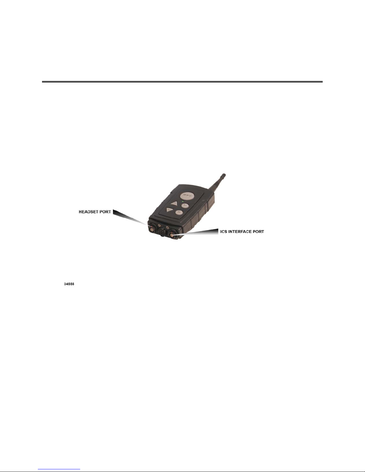
The Dual Port Transceiver (DPT) is typically employed for temporary connections to wired intercom
systems. When connected to the wired system, it acts like a TAP and is usually the network master.
However it only has one interface connector. Depending on configuration, the DPT may also be used
as a handheld unit. See Figure 4.1-1.
Figure 4.1-1. Dual Port Transceiver
When used as an interface to wired intercom systems, the DPT connects to the wired system via an
application specific interface cable. Due to its connector arrangement, an application specific cable is
required to connect most headsets. The unit is powered from three AA NiMH or alkaline batteries.
TM115007 REV A (04/07) 4-1
USE OR DISCLOSURE OF DATA CONTAINED ON TH IS PAGE IS SUBJECT TO THE
RESTRICTION ON THE TITLE PAGE OF THIS DOCUMENT.
Page 38
T ELEPHONICS C ORPORATION
C
OMMUNICATION S YSTEMS D IVISION
4.2 PHYSICAL DESCRIPTION
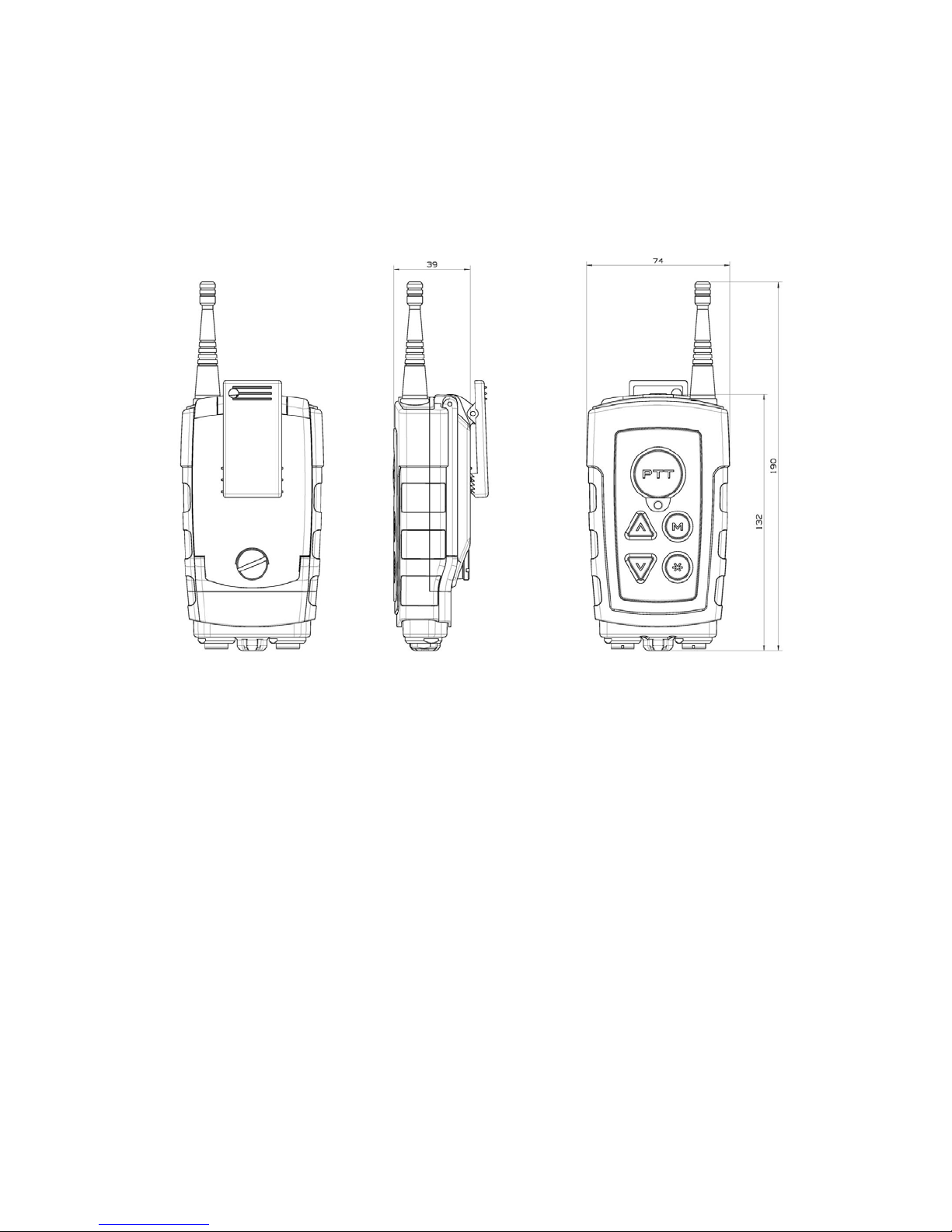
The Dual Port TPT has the same physical characteristics as the TPT with the exception of the
connector interface. The Dual Port TPT uses multiple pinned connectors on the bottom of the unit
instead of a single Nexus connection as is on the TPT. See Figure 4.2-1.
Figure 4.2-1. Dual Port Transceiver (DPT) Unit Dimensions
4.3 OPERATION
The operation of the DPT is similar to the TPT. Functions such as power up/down, SynVoice
messages, battery installation, status indications, etc., follow the descriptions shown for the TPT.
Please refer to that section for details.
Note
Rechargeable batteries (NiMH) must be
removed from the DPT and charged in a
commercial battery charger. The TruLink
Support Station, 780-3000-001, cannot be
employed to charge the DPT’s batteries.
TM115007 REV A (04/07) 4-2
USE OR DISCLOSURE OF DATA CONTAINED ON TH IS PAGE IS SUBJECT TO THE
RESTRICTION ON THE TITLE PAGE OF THIS DOCUMENT.
Page 39

T ELEPHONICS C ORPORATION
C
OMMUNICATION S YSTEMS D IVISION
4.3.1 ICS Interface
The Dual Port Transceiver connects to the wired system via an interface cable. This cable is specific
to the type of wired system. Different interface cables are used in various aircraft/vehicles. When
connecting a Dual Port TPT, the crew station must be configured correctly or echo will occur.
Typically, the DPT is the network MASTER. See the correct addendum for your installation.
After the cable is connected and the unit is powered up slave TPTs can be turned on. They will log
on to the master DPT
In order to set up the channel on a Dual Port TPT, the user must plug in the programming cable to the
Headset Port and then connect a headset to the cable. Channel selection is the same as a TPT.
4.3.2 Logging on to a Network
When used for wired intercom system interface, the DPT will always act as a MASTER. Therefore
it will start a network at power-up and will always succeed in the network logon. The Dual Port TPT
should be powered up before any TPTs are turned on. For a description of how to logon a TPT, see
Paragraph 2.7.3.2.
Note
This procedure is provided for reference only.
Due to electrical variations in different
manufacturers products, the procedure may need
to be altered to achieve acceptable results.
When the DPT is configured for use with a wired intercom system, this procedure must be employed
to eliminate echo in the TruLink system caused by the station’s sidetone.
This procedure will eliminate echo on a TPT when a DPT is connected to a wired system.
Set wired system station to intercom selection.
Set wired system station to HOT MIC selection.
Set wired system station volume to approximately 50% setting.
VOX sensitivity set to minimum (if present on station ICS).
Connect the DPT (using the appropriate aircraft interface cable) to the aircraft.
Confirm no headset is connected to the wired system station.
Insure all other stations are not transmitting on the intercom or have an open MIC. If no
headset is connected to a station, no action is required.
Ensure that the station is receiving no long-range radio audio.
Power up the wired system and the DPT.
Power up a TPT and test for echo by speaking to the wired ICS.
TM115007 REV A (04/07) 4-3
USE OR DISCLOSURE OF DATA CONTAINED ON TH IS PAGE IS SUBJECT TO THE
RESTRICTION ON THE TITLE PAGE OF THIS DOCUMENT.
Page 40

T ELEPHONICS C ORPORATION
C
OMMUNICATION S YSTEMS D IVISION
If echo is heard, reduce the station’s volume control slightly until the echo is eliminated.
Echo should be eliminated. If still present, try backing off on the volume knob again slightly until
echo is eliminated. If it is still present, back off again slightly and power OFF then ON. Repeat steps
as necessary to eliminate echo. Turning the Dual Port Transceiver OFF then ON causes the DPT to
train the system.
4.4 DUAL PORT TRANSCEIVER CHECK OUT PROCEDURE
The following should be performed before using a Dual Port Transceiver:
Ensure that the unit uses fresh alkaline cells or newly charged NiMH cells.
Start up the Dual Port TPT and see if a SLAVE TPT can log onto it.
Confirm that audio conversations are possible with all connected parties (see configuration
addendum).
TM115007 REV A (04/07) 4-4
USE OR DISCLOSURE OF DATA CONTAINED ON TH IS PAGE IS SUBJECT TO THE
RESTRICTION ON THE TITLE PAGE OF THIS DOCUMENT.
Page 41
T ELEPHONICS C ORPORATION
C
OMMUNICATION S YSTEMS D IVISION
CHAPTER 5
TRULINK SUPPORT STATION (TSS)
5.1 OVERVIEW
The TSS is a standalone device that provides the ability to charge the commercially available NiMH
batteries while installed in a 780-1000-001 TPT unit, display Built-in Test (BIT) results and set the
channel on up to six transceivers at one time.
5.2 PHYSICAL CHARACTERISTICS
The TSS is powered by standard 120VAC, 60Hz power. The AC power cable, Telephonics Part No.
780-3500-001, is supplied with the TSS. The TSS measures 11.75 inches in length by 9.75 inches
wide by 4.75 inches high and weighs approximately 12 pounds. There are six plug-in brackets
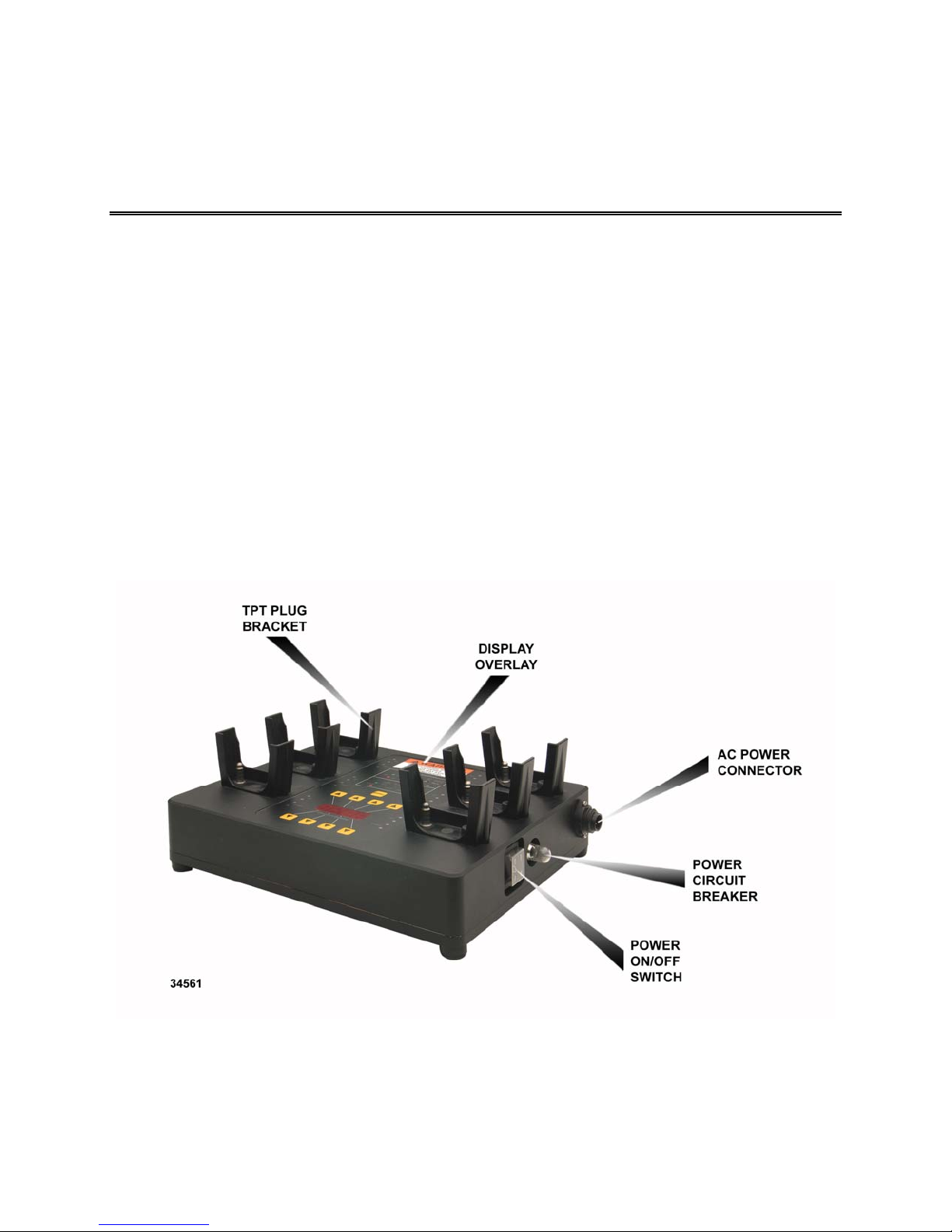
located on top of the TSS. Red and green LEDs provide the status indications for each bracket and a
four digit numeric display is used for TPT channel selection. An ON/OFF switch and a pushbutton
reset circuit breaker are located on the side of the TSS. The TSS controls and indicators are shown in
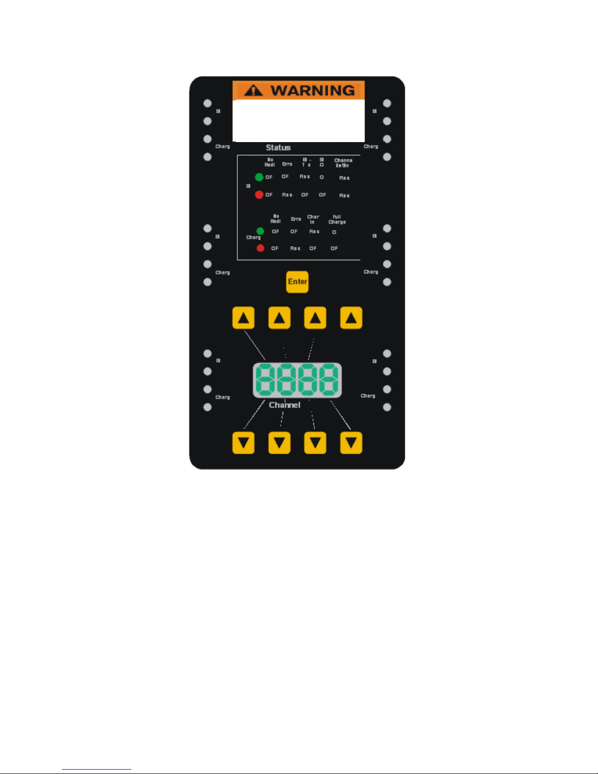
Figure 5.2-1. An enlargement of the display overlay is shown in Figure 5.2-2.
TM115007 REV A (04/07) 5-1
USE OR DISCLOSURE OF DATA CONTAINED ON TH IS PAGE IS SUBJECT TO THE
Figure 5.2-1. TSS Controls and Indicator
RESTRICTION ON THE TITLE PAGE OF THIS DOCUMENT.
Page 42
T ELEPHONICS C ORPORATION
C
OMMUNICATION S YSTEMS D IVISION
DO NOT CHARGE ALKALINE
DO NOT CHARGE ALKALINE
BATTERIES.
BATTERIES.
CHARGING BATTERIES MAY
CHARGING BATTERIES MAY
CAUSE INJURY.
CAUSE INJURY.
Figure 5.2-2. TSS Display Overlay
5.3 CHARGE INDICATION
The display overlay consists of two LEDs (red and green) for charge indication at each TPT plug-in
bracket. The charge LED indications are shown in Table 5.3-1.
TM115007 REV A (04/07) 5-2
USE OR DISCLOSURE OF DATA CONTAINED ON TH IS PAGE IS SUBJECT TO THE
RESTRICTION ON THE TITLE PAGE OF THIS DOCUMENT.
Page 43

T ELEPHONICS C ORPORATION
C
OMMUNICATION S YSTEMS D IVISION
Table 5.3-1
Charge LED Indication
CURRENT STATUS RED LED GREEN LED
No Radio OFF OFF
Error including TPT with non-
FLASHING 50% OFF
rechargeable batteries
Charging OFF FLASHING 50%
Fully charged OFF ON
Radio detected, but charge status
FLASHING 50% FLASHING 50%
from battery not yet updated
5.4 BIT INDICATION
The display overlay consists of two LEDs (red and green) for BIT indication at each TPT plug-in
bracket. The BIT LED indications are shown Table 5.4-1.
Table 5.4-1
BIT LED Indications
CURRENT STATUS RED LED GREEN LED
No Radio OFF OFF
Error FLASHING 50% OFF
Performing BIT OFF FLASHING 50%
BIT OK OFF ON
Setting of Channel FLASHING 50% FLASHING 50%
5.5 TPT CHANNEL SELECTION
This procedure will set the channel for every TPT resident on the TSS. A single TPT cannot be
isolated and set individually.
On the TSS four segment display, use the up and down arrows to select the desired channel
for the TPTs.
Press and release ENTER key once to initiate the change setting. All TPT units will now be
set to the same channel.
TM115007 REV A (04/07) 5-3
USE OR DISCLOSURE OF DATA CONTAINED ON TH IS PAGE IS SUBJECT TO THE
RESTRICTION ON THE TITLE PAGE OF THIS DOCUMENT.
Page 44

T ELEPHONICS C ORPORATION
C
OMMUNICATION S YSTEMS D IVISION
5.6 TSS CHECK OUT PROCEDURE
The following should be performed before using the TSS:
Connect the unit to 120 VAC. Check that the LED digits light up.
For each TPT slot, insert a TPT. Check that the BIT is started.
TM115007 REV A (04/07) 5-4
USE OR DISCLOSURE OF DATA CONTAINED ON TH IS PAGE IS SUBJECT TO THE
RESTRICTION ON THE TITLE PAGE OF THIS DOCUMENT.
Page 45

T ELEPHONICS C ORPORATION
C
OMMUNICATION S YSTEMS D IVISION
APPENDIX A
UNIT SPECIFICATIONS
TM115007 REV A (04/07) A-1
USE OR DISCLOSURE OF DATA CONTAINED ON TH IS PAGE IS SUBJECT TO THE
RESTRICTION ON THE TITLE PAGE OF THIS DOCUMENT.
Page 46

T ELEPHONICS C ORPORATION
C
OMMUNICATION S YSTEMS D IVISION
TPT AND DPT SPECIFICATIONS
DESCRIPTION VALUE
FREQUENCY 2.4 GHz ISM band
RF POWER OUTPUT 100 mW (default)
1 - 100 mW (+20 dBM) factory programmable
RANGE Up to 1500 ft. (unobstructed line-of-sight)
DIMENSIONS 4.8 inches in length by 2.9 inches in width by 1.9
inches in depth
WEIGHT Approximately 11 oz. without batteries
OPERATING TIME 8 Hours Min (3 AA batteries)
PHYSICAL CHANNEL SPACING 300 KHz
3 dB PHYSICAL CHANNEL
192 KHz
BANDWIDTH
MODULATION
π/4 DQPSK
PHYSICAL CHANNEL BIT RATE 384 Kbps
SPEECH ENCODING 32 Kbit/sec ADPCM
NUMBER OF CHANNELS 50
NUMBER OF USERS PER
31
CHANNEL
NUMBER OF SIMULTANEOUS
6
SPEAKERS
SPREAD SPECTRUM Frequency hopping/50 HPS
OPERATING TEMPERATURE -40ºC to +55ºC
TM115007 REV A (04/07) A-2
USE OR DISCLOSURE OF DATA CONTAINED ON TH IS PAGE IS SUBJECT TO THE
RESTRICTION ON THE TITLE PAGE OF THIS DOCUMENT.
Page 47

T ELEPHONICS C ORPORATION
C
OMMUNICATION S YSTEMS D IVISION
TAP SPECIFICATIONS
DESCRIPTION VALUE
FREQUENCY 2.4 GHz ISM band
RF POWER OUTPUT 100 mW (default)
1 - 100 mW (+20 dBM) factory programmable
RANGE Up to 1500 ft. (unobstructed line-of-sight)
DIMENSIONS 8.7 inches in length by 5.7 inches in width by 2.3
inches high
WEIGHT 2.9 lbs
POWER 9-33VDC nominal @ 1A max. Feed must have
1A fuse.
PHYSICAL CHANNEL SPACING 300 KHz
3 dB PHYSICAL CHANNEL
192 KHz
BANDWIDTH
MODULATION
π/4 DQPSK
PHYSICAL CHANNEL BIT RATE 384 Kbps
SPEECH ENCODING 32 Kbit/sec ADPCM
NUMBER OF CHANNELS 50
NUMBER OF USERS PER CHANNEL 31
NUMBER OF SIMULTANEOUS
6
SPEAKERS
SPREAD SPECTRUM Frequency hopping/50 HPS
OPERATING TEMPERATURE -40ºC to +55ºC
TM115007 REV A (04/07) A-3
USE OR DISCLOSURE OF DATA CONTAINED ON TH IS PAGE IS SUBJECT TO THE
RESTRICTION ON THE TITLE PAGE OF THIS DOCUMENT.
Page 48

T ELEPHONICS C ORPORATION
C
OMMUNICATION S YSTEMS D IVISION
TSS SPECIFICATIONS
DESCRIPTION VALUE
INPUT VOLTAGE 120VAC, 50/60 Hz (It is strongly recommended that this
unit be powered from a GFI outlet)
INPUT CURRENT 1A
OPERATING TEMPERATURE 0ºC to +50ºC
STORAGE TEMPERATURE -20ºC to +70ºC
DIMENSIONS 11.75 inches in length by 9.75 inches wide by 4.75 inches
high (no TPT's installed)
WEIGHT Approximately 12 lbs
TM115007 REV A (04/07) A-4
USE OR DISCLOSURE OF DATA CONTAINED ON TH IS PAGE IS SUBJECT TO THE
RESTRICTION ON THE TITLE PAGE OF THIS DOCUMENT.
Page 49

T ELEPHONICS C ORPORATION
C
OMMUNICATION S YSTEMS D IVISION
APPENDIX B
CONNECTOR DATA
TM115007 REV A (04/07) B-1
USE OR DISCLOSURE OF DATA CONTAINED ON TH IS PAGE IS SUBJECT TO THE
RESTRICTION ON THE TITLE PAGE OF THIS DOCUMENT.
Page 50

T ELEPHONICS C ORPORATION
C
OMMUNICATION S YSTEMS D IVISION
LRU ID: TruLink Access Point (TAP)
LRU CONNECTOR: J1 Audio Interface
CONNECTOR STD: MIL-C 38999
MS27468T13B35SN
CONNECTOR MFG'R: SOURIAU MATING CONNECTOR MFG'R: SOURIAU
CONNECTOR P/N: 8LT7C13B35SN MATING CONNECTOR P/N: 8LT5C13B35PN
Signal
Name
AUDIO_IN-
(Note 1)
Signal
Level
-46
dBm to
+12
dBm
Signal
Freq
300
To
3400
Hz
Pin
Number
Protective Cap PN: 8LTE02B13
MATING CONN.
MS27467T13B35PN
Input/
Output
21
Input
Technical
Specs
Nominal: 0 dBm.
Input line impedance
(Audio1_IN): 600 Ohm.
For reference only. See
addendum manual for
actual settings
(RX-path) Placing
different impedance nets
in the connector changes
the impedance. The
signal is transformer
isolated.
Signal
Description
AUDIO_IN+ 14
AUDIO_OUT-
(Note 1)
-99
dBm to
+11
dBm
300
To
3400
Hz
16
Output
Nominal: +10 dBm
Output line impedance
(Audio1_Out): 600 Ohm
For reference only. See
addendum manual for
actual settings
(TX-path) Placing
different impedance nets
in the connector changes
the impedance. The
signal is amplified with
a dual operational
amplifier. The signal is
transformer isolated
AUDIO_OUT+ 2
CTR_DATA_1_OUT- 11
Output
Closed:
Max current: 0.14 A
Max resistance: 15 Ohm
Open:
Max voltage: 30 V
Max leak current: 0.1
Discrete signal. The
signal is isolated by an
optocoupler.
mA
CTR_DATA_1_OUT+ 12
CTR_DATA_1_IN- 4
Input
Non detect:
Max current: 0.18 mA
Max voltage: 0.95 V
Detect:
Min Current: 0.3 mA
Min voltage: 2.2 V
Discrete signal. The
signal is isolated by an
optocoupler.
CTR_DATA_1_IN+ 3
Note 1: Signal levels are factory programmable. Default = -4.4 dBm
TM115007 REV A (04/07) B-2
USE OR DISCLOSURE OF DATA CONTAINED ON TH IS PAGE IS SUBJECT TO THE
RESTRICTION ON THE TITLE PAGE OF THIS DOCUMENT.
Page 51

T ELEPHONICS C ORPORATION
C
OMMUNICATION S YSTEMS D IVISION
LRU ID: TruLink Access Point (TAP)
LRU CONNECTOR: J2 Data Interface Protective Cap P/N: 8LTE02B09
CONNECTOR STD: MIL-C 38999
MS27468T09B35SN
CONNECTOR MFG'R: SOURIAU MATING CONNECTOR MFG'R: SOURIAU
CONNECTOR P/N: 8LT7C09B35SN MATING CONNECTOR P/N: 8LT5C09B35PN
Signal
Name
RX
Signal
Level
RS23
2
Signal
Freq
Max
115.2
Number
MATING CONN.
MS27467T09B35PN
Pin
Input/
Output
4
Input/
Output
kbit/s
Technical
Specs
VT100 or ANSI
compatible. ASCII transfer
protocol.
8 bit data, 1 stop bit,
No parity, 38400 baud.
Description
Asynchronous data
interface. This interface
consists of two RS-232
lines. The RS-232
transceiver is a
SP3232EEA from
SIPEX.
TX 6
GND 1
Signal
TM115007 REV A (04/07) B-3
USE OR DISCLOSURE OF DATA CONTAINED ON TH IS PAGE IS SUBJECT TO THE
RESTRICTION ON THE TITLE PAGE OF THIS DOCUMENT.
Page 52

T ELEPHONICS C ORPORATION
C
OMMUNICATION S YSTEMS D IVISION
LRU ID: TruLink
LRU CONNECTOR: J3 Audio Interface
CONNECTOR STD: MIL- MIL-C 38999
MS27468T13B35SA
CONNECTOR MFG'R: SOURIAU MATING CONNECTOR MFG'R: SOURIAU
CONNECTOR P/N: 8LT7C13B35SA MATING CONNECTOR P/N: 8LT5C13B35PA
Signal
Name
AUDIO_IN(Note 1)
Access Point (TAP)
Signal
Level
-77
dBm to
-2
dBm
Signal
Freq
300
To
3400
Hz
MATING CONN.
MS27467T13B35PA
Pin
Number
21
Input/
Output
Input
Technical
Specs
Nominal 0 dBm.
Input line impedance
(Audio1_IN): 600 Ohm.
For reference only. See
addendum manual for
actual settings
(RX-path) Placing
different impedance nets
in the connector changes
the impedance. The
signal is transformer
isolated.
Description
Signal
AUDIO_IN+ 14
AUDIO_OUT(Note 1)
-99
dBm to
+11
dBm
300
To
3400
Hz
16
Output
Nominal 0 dBm.
Output line impedance
(Audio1_Out): 600
Ohm. For reference only.
See addendum manual
for actual settings
(TX-path) Placing
different impedance nets
in the connector changes
the impedance. The
signal is amplified with a
dual operational
amplifier. The signal is
transformer isolated
AUDIO_OUT+ 2
CTR_DATA_1_OUT- 11
Output
Closed:
Max current: 0.14 A
Max resistance: 15 Ohm
Open:
Max voltage: 30 V
Max leak current: 0.1
Discrete signal. The
signal is isolated by an
optocoupler.
mA.
CTR_DATA_1_OUT+ 12
CTR_DATA_1_IN- 4
CTR_DATA_1_IN+ 3
Note 1: Signal levels are factory programmable. Default = -4.4 dBm
TM115007 REV A (04/07) B-4
USE OR DISCLOSURE OF DATA CONTAINED ON TH IS PAGE IS SUBJECT TO THE
Non detect:
Max current: 0.18 mA
Max voltage: 0.95 V
Input
Detect:
Min Current: 0.3 mA
Min voltage: 2.2 V
RESTRICTION ON THE TITLE PAGE OF THIS DOCUMENT.
Discrete signal. The
signal is isolated by an
optocoupler.
Page 53

T ELEPHONICS C ORPORATION
C
OMMUNICATION S YSTEMS D IVISION
LRU ID: TruLink
LRU CONNECTOR: J4 Data Interface Protective Cap P/N: 8LTE02B09
CONNECTOR STD: MIL-C 38999
MS27468T09B35SA
CONNECTOR MFG'R: SOURIAU MATING CONNECTOR MFG'R: SOURIAU
CONNECTOR P/N: 8LT7C09B35SA MATING CONNECTOR P/N: 8LT5C09B35PA
Signal
Name
Data Hi
Access Point (TAP)
Signal
Level
RS48
5
Signal
Freq
2
Mbps
MATING CONN.
MS27467T09B35PA
Pin
Number
Input/
Output
6
Input/
Output
Technical
Specs
Signal
Description
Not yet implemented High Speed Data Bus.
This interface consists of
two RS485 lines. The
RS485 transceiver is a
MAX3485 from MAXIM.
The direction is
configured by the FPGA.
The signals have over
voltage protection and
EMI-filters.
Data Lo 5
Clock Hi 4
Clock Lo 3
GND 1
TM115007 REV A (04/07) B-5
USE OR DISCLOSURE OF DATA CONTAINED ON TH IS PAGE IS SUBJECT TO THE
RESTRICTION ON THE TITLE PAGE OF THIS DOCUMENT.
Page 54

T ELEPHONICS C ORPORATION
C
OMMUNICATION S YSTEMS D IVISION
LRU ID: TruLink™
LRU CONNECTOR: J5 Audio Interface Protective Cap PN: 8LTE02B13
CONNECTOR STD: MIL--C 38999
MS27468T13B35SB
CONNECTOR MFG'R: SOURIAU MATING CONNECTOR MFG'R: SOURIAU
CONNECTOR P/N: 8LT7C13B35SB MATING CONNECTOR P/N: 8LT5C13B35PB
Signal
Name
AUDIO_IN(Note 1)
Access Point (TAP)
Signal
Level
Signal
-46
dBm
to
+10
dBm
Freq
300
To
3400
Hz
MATING CONN.
MS27467T13B35PB
Pin
Number
21
Input/
Output
Input
Technical
Specs
Nominal 0 dBm.
Input line impedance
(Audio1_IN): 600 Ohm.
For reference only. See
addendum manual for
actual settings
(RX-path) Placing
different impedance nets
in the connector changes
the impedance. The
signal is transformer
isolated.
Signal
Description
AUDIO_IN+ 14
AUDIO_OUT(Note 1)
-99
dBm
to +11
dBm
300
To
3400
Hz
16
Output
Nominal -10 dBm.
Output line impedance
(Audio1_Out): 600 Ohm
For reference only. See
addendum manual for
actual settings
(TX-path) Placing
different impedance nets
in the connector changes
the impedance. The
signal is amplified with a
dual operational
amplifier. The signal is
transformer isolated
AUDIO_OUT+ 2
CTR_DATA_1_OUT- 11
Output
Closed:
Max current: 0.14 A
Max resistance: 15 Ohm
Open:
Max voltage: 30 V
Max leak current: 0.1
Discrete signal. The
signal is isolated by an
optocoupler.
mA.
CTR_DATA_1_OUT+ 12
CTR_DATA_1_IN- 4
Input
Non detect:
Max current: 0.18 mA
Max voltage: 0.95 V
Detect:
Min Current: 0.3 mA
Min voltage: 2.2 V
Discrete signal. The
signal is isolated by an
optocoupler.
CTR_DATA_1_IN+ 3
Note 1: Signal levels are factory programmable. Default = -4.4 dBm
TM115007 REV A (04/07) B-6
USE OR DISCLOSURE OF DATA CONTAINED ON TH IS PAGE IS SUBJECT TO THE
RESTRICTION ON THE TITLE PAGE OF THIS DOCUMENT.
Page 55

T ELEPHONICS C ORPORATION
C
OMMUNICATION S YSTEMS D IVISION
POWER
LRU ID: TruLink
LRU CONNECTOR: Power
CONNECTOR STD: MIL-C 26482 MATING CONN.
CONNECTOR MFG'R: CANNON MATING CONNECTOR MFG'R: CANNON
CONNECTOR P/N: KPT02E-14-5P MATING CONNECTOR P/N: KPT06E14-5S
Signal
Name
+28VDC
Access Point (TAP)
Signal
Level
DC
DC
Signal
Freq
MS3116E14-5S
Pin
Number
A, B
Input/
Output
Input
Technical
Specs
Fused protected 60V,
650mA.
Current consumption,
12V, without load: 4.8
mA.
PTC-resistor: 650 mA
Supply voltage: 9 to 33
VDC.
User must protect with
1A circuit breaker.
Description
Signal
Tranzorb: 39V
+28VRTN DC DC C, D, E
ANTENNA
LRU ID: TruLink
LRU CONNECTOR: ANT
CONNECTOR TNC FEMALE- MATING CONN.
CONNECTOR MFG'R: TBD MATING CONNECTOR MFG'R: TBD
CONNECTOR P/N: TBD (TNC FEMALE) MATING CONNECTOR P/N: TBD (TNC
Signal
Name
Antenna
Access Point (TAP)
Signal
Type
RF
Antenna
Pin
Number
1
MALE)
Input/
Output
Input/Output
Technical
Specs
Frequency Range: 2,400
MHz to 2,484 MHz
RF transmit / receive
signal. Connection to a
Signal
Description
50 Ohm antenna
TM115007 REV A (04/07) B-7
USE OR DISCLOSURE OF DATA CONTAINED ON TH IS PAGE IS SUBJECT TO THE
RESTRICTION ON THE TITLE PAGE OF THIS DOCUMENT.
Page 56
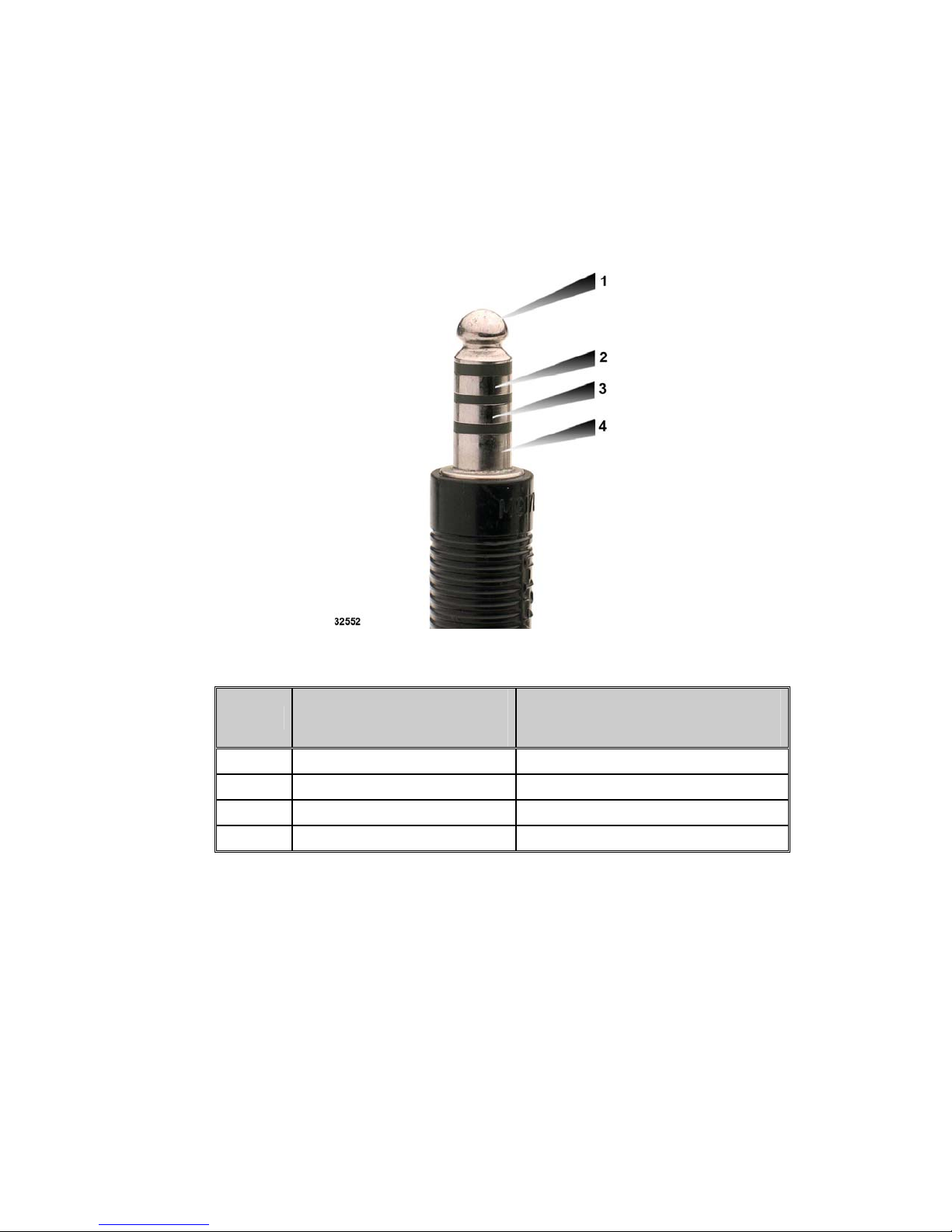
T ELEPHONICS C ORPORATION
C
OMMUNICATION S YSTEMS D IVISION
TPT CONNECTORS
The TPT connector is a female 4-pole NEXUS receptacle.
The TPT connection is designed for use with a NEXUS plug connector having four segmented
connections as shown:
SIGNAL NAME
PIN NO.
HEADSET MODE
(NOTE 1)
1 MIC+ RXD (RS 232)
2 Earphone+ Ground
3 MIC- TXD (RS 232)
4 Earphone- Power
Note 1: Headset mode defines operation when a headset is plugged into the TPT.
Note 2: Power/Data mode defines operation when TPT is installed in TSS
SIGNAL NAME
POWER/DATA MODE
(NOTE 2)
TM115007 REV A (04/07) B-8
USE OR DISCLOSURE OF DATA CONTAINED ON TH IS PAGE IS SUBJECT TO THE
RESTRICTION ON THE TITLE PAGE OF THIS DOCUMENT.
Page 57

T ELEPHONICS C ORPORATION
C
OMMUNICATION S YSTEMS D IVISION
TSS CONNECTORS
Power Input
Connector: AMPENOL T3110000
Pin 1 – Neutral
Pin 2 – Line
Pin 3 – Not Connected
Pin 4 - Ground
TPT Plug-in Bracket Connector for SS.
The TPT plug-in bracket connector is a NEXUS plug connector having four segmented connections
as shown below:
DUAL PORT TRANSCEIVER CONNECTORS
Headset Interface
The connector is a female 7-pole ODU/Lemo type jack.
CONNECTOR PIN-OUT
The pin-out of the connector is defined as:
TM115007 REV A (04/07) B-9
USE OR DISCLOSURE OF DATA CONTAINED ON TH IS PAGE IS SUBJECT TO THE
Figure 1. Headset Connector Outside View
RESTRICTION ON THE TITLE PAGE OF THIS DOCUMENT.
Page 58

T ELEPHONICS C ORPORATION
C
OMMUNICATION S YSTEMS D IVISION
Table 1
Pin-out of 7-Pole Headset Jack
PIN NR J2 SIGNAL NAME COMMENT
1 MIC+
2 MIC-
3 Earphone Left +
4 Earphone Left -
5 Earphone Right +
6 Earphone Right -
7 Control input
EXTERNAL AUDIO/DATA INTERFACE
Connector type
The connector is a female 8-pole ODU/Lemo type jack.
Figure 2. External Audio/Data Interface
CONNECTOR PIN-OUT
The pin-out of the connector is defined as:
TM115007 REV A (04/07) B-10
USE OR DISCLOSURE OF DATA CONTAINED ON TH IS PAGE IS SUBJECT TO THE
RESTRICTION ON THE TITLE PAGE OF THIS DOCUMENT.
Page 59

T ELEPHONICS C ORPORATION
C
OMMUNICATION S YSTEMS D IVISION
Table 2
Pin-out of 8-Pole Audio Jack
PIN NR J3 SIGNAL NAME COMMENT
1 Audio IN +
2 CTRL_DATA2_IN
3 Audio OUT +
4 CTRL_DATA1_OUT
5 DATA_IN_EXT RS-232
6 DATA_OUT_EXT RS-232
7 Power IN 11 – 15 V DC
8 GND
TM115007 REV A (04/07) B-11
USE OR DISCLOSURE OF DATA CONTAINED ON TH IS PAGE IS SUBJECT TO THE
RESTRICTION ON THE TITLE PAGE OF THIS DOCUMENT.
 Loading...