

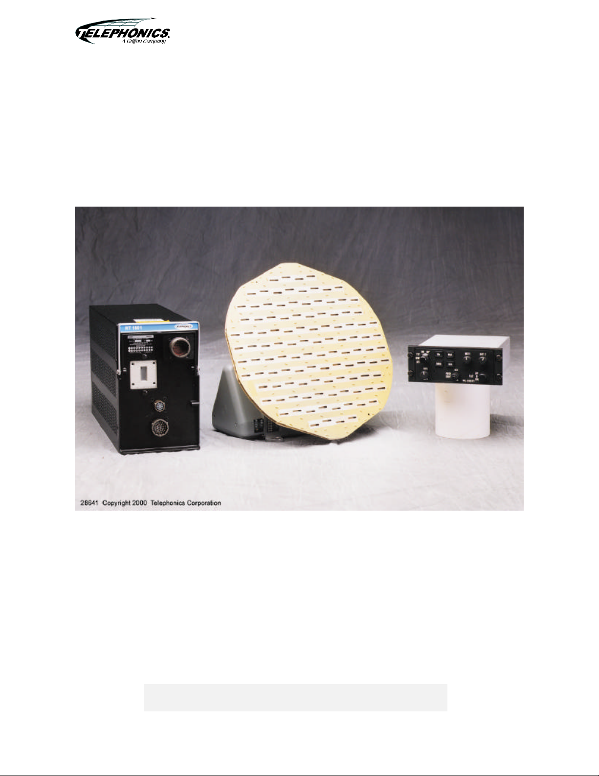
Telephonics MCB-RT-1601 installation manual

RADAR 1600RADAR 1600
WEATHER RADAR SYSTEMWEATHER RADAR SYSTEM
INSTALLATION MANUALINSTALLATION MANUAL
TM106601 (7/01)
July 2001
Prepared by:
TELEPHONICS CORPORATION
815 Broad Hollow Road
Farmingdale, New York 11735
USA
C
OMMAND SYSTEMS DIVISION
This publication may not be reproduced in part or in whole without the
WEATHER RADAR SYSTEMWEATHER RADAR SYSTEM
INSTALLATION MANUALINSTALLATION MANUAL
RDRRDR--16001600
Copyright © 1995/2001 Telephonics Corporation
Publication No.: TM106601
All Rights Reserved
Printed in U.S.A.
Telephonics Corporation, Command Systems Division (CSD)
815 Broad Hollow Road, Farmingdale, New York 11735
Telephone: (877) 517-2327 Fax: (877) 755-7701
expressed written consent of Telephonics Corporation.
TM106601 (7/01)

C
OMMAND SYSTEMS DIVISION
Maintain prescribed safe distance when standing
in front of radiating antenna.
Never expose eyes or any part of the body to an
unterminated wave guide.
CAUTION
TM106601_(7/01) FMi
USE OR DISCLOSURE OF DATA CONTAINED ON THIS PAGE IS SUBJECT TO THE
RESTRICTION ON THE TITLE PAGE OF THIS DOCUMENT.
C
OMMAND SYSTEMS DIVISION
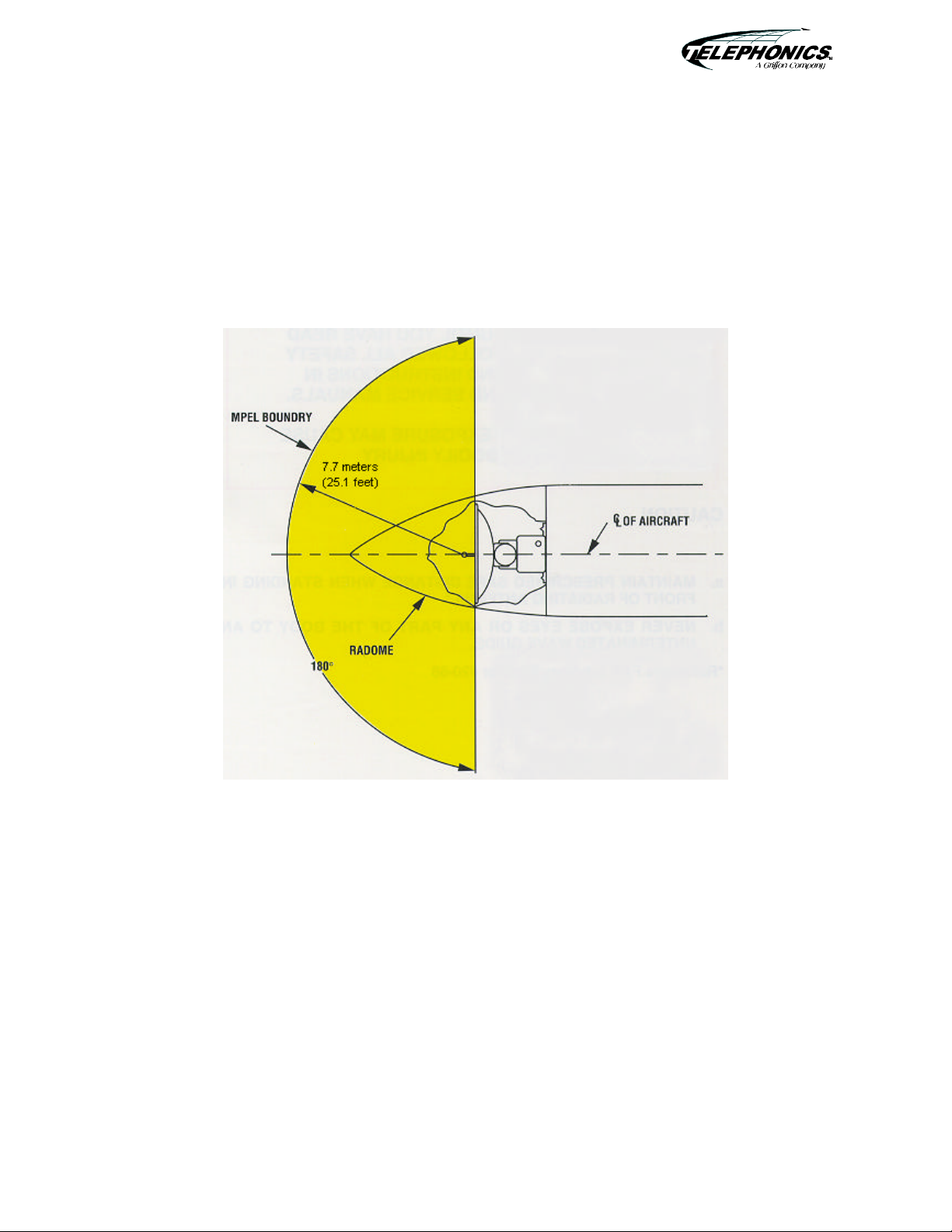
MAXIMUM PERMISSIBLE EXPOSURE LEVEL (MPEL)
In order to avoid the envelope in which the radiation level exceeds the U.S. Government standard of
1 mW per square centimeter, all personnel should remain beyond the distance indicated in the
illustration below. The distance to the MPEL boundary is calculated upon the basis of the largest
antenna available with the RDR-1600 system, rated output power of the transmitter and in the nonrotating or boresight position of the antenna. With a scanning beam, the power density at the MPEL
boundary is significantly reduced.
TM106601_(7/01) FMii
USE OR DISCLOSURE OF DATA CONTAINED ON THIS PAGE IS SUBJECT TO THE
RESTRICTION ON THE TITLE PAGE OF THIS DOCUMENT.

C
OMMAND SYSTEMS DIVISION
INSTALLATION MANUAL
RDR-1600 WEATHER RADAR SYSTEM
AC 20-68B
DATE 8/8/80
DEPARTMENT OF TRANSPORTATION
Federal Aviation Administration
Washington, D.C.
—————————————————————————————————
—————————————————————————————————
Subject: RECOMMENDED RADIATION SAFETY PRECAUTIONS FOR GROUND OPERATION OF
1. PURPOSE. This circular sets forth recommended radiation safety precautions to be taken by
personnel when operating airborne weather radar on the ground.
2, CANCELLATION. Ac 20-68A, dated April 11, 1975, is canceled.
3. RELATED READING MATERIAL.
a. Barnes and Taylor, Radiation Hazards and Protection (London: George Nevnes Limited, 1963).
P. 211.
b. U.S. Department of Health, Education and Welfare, Public Health Service, Consumer
Protection and Environmental Health Service, “Environmental health microwave, ultraviolet radiation and
radiation from lasers and television receivers – An Annotated Bibliography,” FS 2.300: RH-35,
Washington, U.S. Government Printing Office, pp. 56-57.
c. Mumford, W.W., “Some technical aspects of microwave radiation hazards,” Proceedings of the
IRE, Washington, U.S. Government Printing Office, February 1961, pp. 427-447.
4. BACKGROUND. Dangers from ground operation of airborne weather radar include the possibility
of human body damage and ignition of combustible materials by radiated energy. Low tolerance parts of
the body include the eyes and testes.
5. PRECAUTIONS. Management and supervisory personnel should establish procedures for advising
personnel of dangers from operating airborne weather radars on the ground. Precautionary signs should
be displayed in affected areas to alert personnel of ground testing.
a. GENERAL.
AIRBORNE WEATHER RADAR
(1) Airborne weather radar should be operated on the ground only by qualified personnel.
—————————————————————————————————
TM106601_(7/01) FMiii
USE OR DISCLOSURE OF DATA CONTAINED ON THIS PAGE IS SUBJECT TO THE
RESTRICTION ON THE TITLE PAGE OF THIS DOCUMENT.

C
OMMAND SYSTEMS DIVISION
INSTALLATION MANUAL
RDR-1600 WEATHER RADAR SYSTEM
AC 20-68B 8/8/80
(2) Installed airborne radar should not be operated while the aircraft is in a hangar or other
enclosure unless the radar transmitter is not operating, or the energy is directed toward an absorption
shield which dissipates the radio frequency energy. Otherwise, radiation within the enclosure can be
reflected throughout the area.
b. Body Damage. To prevent possible human body damage, the following precautions should be
taken:
(1) Personnel should never stand nearby and in front of a radar antenna which is
transmitting. When the antenna is not scanning, the danger increases.
(2) A recommended safe distance from operating airborne weather radars should be
established. A safe distance can be determined by using the equations in Appendix 1 or the graphs of
figures 1 and 2. This criterion is now accepted by many industrial organizations and is based on limiting
exposure of humans to an average power density not greater than 10 milliwatts per square centimeter.
(3) Personnel should be advised to avoid the end of an open waveguide unless the radar is
turned off.
(4) Personnel should be advised to avoid looking into a waveguide, or into the open end of a
coaxial connector or line connector to a radar transmitter output, as severe eye damage may result.
(5) Personnel should be advised that when high power radar transmitters are operated out of
their protective cases, X-rays may be emitted. Stray X-rays may emanate from the glass envelope type
pulser, oscillator, clipper, or rectifier tubes, as well as magnetrons.
c. Combustible Materials. To prevent possible fuel ignition, an installed airborne weather radar
should not be operated while an aircraft is being refueled or defueled.
M.C. BEARD
Director of Airworthiness
TM106601_(7/01) FMiv
USE OR DISCLOSURE OF DATA CONTAINED ON THIS PAGE IS SUBJECT TO THE
RESTRICTION ON THE TITLE PAGE OF THIS DOCUMENT.

C
INSTALLATION MANUAL
RDR-1600 WEATHER RADAR SYSTEM
AC NO: 43-14
DATE: 2/24/77
OMMAND SYSTEMS DIVISION
DEPARTMENT OF TRANSPORTATION
FEDERAL AVIATION ADMINISTRATION
SUBJECT: MAINTENANCE OF WEATHER RADAR RADOMES
—————————————————————————————————
1. PURPOSE. This advisory circular provides guidance material useful to repair facilities in the
maintenance of weather radar radomes.
2. CANCELLATION. AC 43-202, dated 6/11/65, and AC 90-20, dated 11/12/64, are cancelled.
3. GENERAL. A radome is a covering whose primary purpose is to protect a radar antenna from the
elements. It is a part of the airframe and, therefore, should have certain physical as well as
electrical properties. Physically, a radome should be strong enough to withstand the airloads that it
will encounter and it should be contoured to minimize drag. These properties vary with the shape,
design speed, and size of the airplane on which it is to be installed. Electrically, a radome should
permit the passage of the radar’s transmitted signals and return echoes with minimum distortion
and absorption. In order to do this, it should have a certain electrical thickness. The electrical
thickness of a radome is related to the physical thickness, operating frequency, and the types of
material and construction used. This relationship is defined by a number of complex mathematical
equations which are of interest only to radome design engineers. These equations show that, for
given physical properties, a radome should have a certain electrical thickness for a certain narrow
range of operating frequencies. (This is the reason why C-band radomes will not give optimum
performance with X-band radars and vice versa.) Also, a very small variation in physical thickness
may cause a sizable variation in electrical thickness. Radar efficiency, definition, and accuracy of
display depend upon a clear, nondistorted, reflection-free antenna view through the radome.
Consequently, a radome should be precisely built for optimum performance.
4. RADOME CHARACTERISTICS. There are two general types of radomes, the “thin wall” and
“sandwich” types. Thin wall radomes are considered to be thin relative to the wavelength of the
radar. They are generally useful when the radar frequency is low enough to permit a skin
thickness which will satisfy the structural requirements. Sandwich radomes consist of two
—————————————————————————————————
Initiated by: AFS-804
TM106601_(7/01) FMv
USE OR DISCLOSURE OF DATA CONTAINED ON THIS PAGE IS SUBJECT TO THE
RESTRICTION ON THE TITLE PAGE OF THIS DOCUMENT.

C
OMMAND SYSTEMS DIVISION
INSTALLATION MANUAL
RDR-1600 WEATHER RADAR SYSTEM
AC 43-14 2/24/77
or more plastic skins separated by a dielectric core. The core may consist of honeycomb plastic
section, hollow flutes, or foam plastic. The dielectric and separation of the skins will depend
upon the wavelength of the radar frequency or frequencies.
5. RADOME DAMAGE. Probably the most frequent damage to radomes is holes in the structure
caused by static discharges. These can be large holes that are readily apparent, or small pin
holes that are almost imperceptible. Any hole, regardless of size, can cause major damage to a
radome since moisture can enter the radome wall and cause internal delamination. If the
moisture freezes, more serious damage may occur. If enough moisture collects, the radiation
pattern will be distorted and the transmitted signals and return echoes seriously attenuated.
Ram air through a hole can delaminate and break the inner surface of the radome and result in
separation of the skins or faces of the material from the core, weakening the radome structure.
Other types of damage are characterized as dents and scratches caused by impact with stones
and birds and improper handling of the radome when it is removed for maintenance of the radar
antenna. This type of damage is easily found by inspection.
6. MAINTENANCE.
a. High performance radar radomes are very precisely constructed and sometimes the
slightest change in their physical characteristics, such as excessive layers of paint, can
adversely affect radar system performance. All repairs to radomes, no matter how minor,
should return the radome to its original or properly altered condition, both electrically and
structurally. The performance of proper maintenance to precision radomes requires special
knowledge and techniques and the use of proper tools and materials. An improper minor
repair can eventually lead to an expensive major repair. A radome having undergone major
repairs should be tested to ascertain that its electrical properties have not been impaired.
The testing of radomes requires test equipment that usually is found only in repair facilities
specializing in radome maintenance. Even minor repairs may affect one or all of the
following:
(1) Transmissivity. Which is the ability of a radome to pass radar energy through it.
(2) Reflection. Which is the return or reflection of the outgoing radar energy from the
radome back into the antenna and waveguide system
(3) Diffraction. Which is the bending of the radar energy as it passes through the radome.
b. These electrical properties, when altered by improper repair, may cause loss of signal,
distortion and displacement of targets, and can clutter the display to obscure the target. Poor
radome
Page 2 Par 4
TM106601_(7/01) FMvi
USE OR DISCLOSURE OF DATA CONTAINED ON THIS PAGE IS SUBJECT TO THE
RESTRICTION ON THE TITLE PAGE OF THIS DOCUMENT.

C
OMMAND SYSTEMS DIVISION
INSTALLATION MANUAL
RDR-1600 WEATHER RADAR SYSTEM
2/24/77 AC 43-14
electrical performance can produce numerous problems which may appear to be symptoms of
deficiencies in other units of the radar system. The following are examples of improper repair:
(1) Use of wrong materials - not compatible with original radome materials.
(2) Patches of different thickness.
(3) Poor fabrication techniques.
(4) Nonvoid-free patches
(5) Repairs overlapping.
(6) ‘Holes plugged with resin, screws, metal, wood, and plastic plugs.
(7) Cuts or cracks simply coated with resin
(8) Tape (including electrical tape) over hole or crack and covered with resin.
(9) Oversize patches.
(10) Too much or too little resin
(11) Exterior coatings - too many coats, too thick, uneven thickness - metallic base paints
(12) Filled honeycomb cells.
(13) Repairs made without removing moisture or moisture contamination from inside of
radome wall.
(14) Abrupt changes in cross-sectional areas.
(15) Patches projecting above outside contour lines.
(16) Improper cure.
(17) Wrong size cells or density of honeycomb.
(18) Excessive overlap in honeycomb joints.
(19) poor bonding of skin to core.
(20) Gaps in honeycomb core.
Par 6 Page 3
TM106601_(7/01) FMvii
USE OR DISCLOSURE OF DATA CONTAINED ON THIS PAGE IS SUBJECT TO THE
RESTRICTION ON THE TITLE PAGE OF THIS DOCUMENT.

C
OMMAND SYSTEMS DIVISION
INSTALLATION MANUAL
RDR-1600 WEATHER RADAR SYSTEM
AC 43-14 2/24/77
7. RECOMMENDATION. Both the physical and electrical properties of radomes should be given
careful consideration during repair operations. These properties are carefully controlled during
manufacture and should not be altered by improper repairs.
J.A. FERRARESE
Acting Director, Flight Standards Service
TM106601_(7/01) FMviii
USE OR DISCLOSURE OF DATA CONTAINED ON THIS PAGE IS SUBJECT TO THE
RESTRICTION ON THE TITLE PAGE OF THIS DOCUMENT.

C
OMMAND SYSTEMS DIVISION
TABLE OF CONTENTS
PARAGRAPH TITLE PAGE
CHAPTER 1. GENERAL INFORMATION ....................................................................................... 1-1
1.1 GENERAL ERROR! BOOKMARK NOT DEFINED.
1.1.1 Basic System Functions..................................................1-Error! Bookmark not defined.
1.1.2 Operational Modes..........................................................1-Error! Bookmark not defined.
1.1.2.1 Search Modes..................................................................1-Error! Bookmark not defined.
1.1.2.2 Weather Avoidance Modes.............................................1-Error! Bookmark not defined.
1.1.2.3 Beacon Mode...................................................................1-Error! Bookmark not defined.
1.1.2.4 Dual Mode of Operation.................................................1-Error! Bookmark not defined.
1.2 EQUIPMENT PART NUMBERS AND DESCRIPTIONS..............................................1-
ERROR! BOOKMARK NOT DEFINED.
1.2.1 RDR-1600 System Components.....................................1-Error! Bookmark not defined.
1.2.2 CP-113 Unit Description................................................1-Error! Bookmark not defined.
1.2.2.1 CP-113 Function Select Switch......................................1-Error! Bookmark not defined.
1.2.2.2 CP-113 Mode Push Buttons...........................................1-Error! Bookmark not defined.
1.2.2.3 CP-113 Additional Switches and Controls.....................1-Error! Bookmark not defined.
1.3 ADDITIONAL EQUIPMENT REQUIRED FOR COMPLETE INSTALLATION........1-
ERROR! BOOKMARK NOT DEFINED.
1.3.1 Additional Available Equipment ....................................1-Error! Bookmark not defined.
1.3.2 Equipment Required But Not Supplied..........................1-Error! Bookmark not defined.
1.4 LEADING PARTICULARS......................1-ERROR! BOOKMARK NOT DEFINED.
1.4.1 RDR-1600 Radar System...............................................1-Error! Bookmark not defined.
1.4.2 RT-1601 Receiver Transmitter.......................................1-Error! Bookmark not defined.
1.4.3 DA-1203A Antenna Drive..............................................1-Error! Bookmark not defined.
1.4.4 CP-113 Radar Control Panel..........................................1-Error! Bookmark not defined.
1.4.5 Antennas..........................................................................1-Error! Bookmark not defined.
1.5 SYSTEM COMPONENT DESCRIPTION1-ERROR! BOOKMARK NOT DEFINED.
1.5.1 General............................................................................1-Error! Bookmark not defined.
1.5.2 RT-1601 Receiver Transmitter.......................................1-Error! Bookmark not defined.
1.5.3 DA-1203A Antenna Drive..............................................1-Error! Bookmark not defined.
1.5.4 CP-113 Radar Control Panel..........................................1-Error! Bookmark not defined.
1.5.5 Antennas..........................................................................1-Error! Bookmark not defined.
1.6 EQUIPMENT OPERATION AND CONTROLS.............................................................1-
ERROR! BOOKMARK NOT DEFINED.
1.6.1 Operating Precautions.....................................................1-Error! Bookmark not defined.
1.6.2 License Requirements.....................................................1-Error! Bookmark not defined.
1.6.3 Operating Controls and Display Features.......................1-Error! Bookmark not defined.
1.6.3.1 CP-113 Operating Controls............................................1-Error! Bookmark not defined.
1.6.3.2 MFD Display...................................................................1-Error! Bookmark not defined.
1.6.4 Operating Procedures......................................................1-Error! Bookmark not defined.
1.6.4.1 General............................................................................1-Error! Bookmark not defined.
1.6.4.2 Turn On Procedure..........................................................1-Error! Bookmark not defined.
1.6.4.3 Primary Mode Selection Procedures (WX, WXA, SR1, SR2, SR3, BCN).......................1-
Error! Bookmark not defined.
1.6.4.4 Range Selection Procedure..............................................1-Error! Bookmark not defined.
1.6.4.5 Stabilization (STAB OFF) Control Procedure...............1-Error! Bookmark not defined.
TM106601_(7/01) i
USE OR DISCLOSURE OF DATA CONTAINED ON THIS PAGE IS SUBJECT TO THE
RESTRICTION ON THE TITLE PAGE OF THIS DOCUMENT.

C
OMMAND SYSTEMS DIVISION
1.6.4.6 TEST Pattern Selection Procedure..................................1-Error! Bookmark not defined.
1.6.4.7 60° Scan Selection Procedure.........................................1-Error! Bookmark not defined.
1.6.4.8 Beacon Mode Selection (BCN).......................................1-Error! Bookmark not defined.
1.6.4.9 Two-Pulse Beacon Interrogation and Codes ..................1-Error! Bookmark not defined.
TM106601_(7/01) ii
USE OR DISCLOSURE OF DATA CONTAINED ON THIS PAGE IS SUBJECT TO THE
RESTRICTION ON THE TITLE PAGE OF THIS DOCUMENT.

C
OMMAND SYSTEMS DIVISION
TABLE OF CONTENTS
[continued]
PARAGRAPH TITLE PAGE
1.6.4.10 DO-172 Six-Pulse Beacon Interrogation........................1-Error! Bookmark not defined.
1.6.4.11 Target Alert Function......................................................................................................1-31
1.7 ASSOCIATED PUBLICATIONS ...........1-3ERROR! BOOKMARK NOT DEFINED.
CHAPTER 2. INSTALLIATION.......................................................................................................... 2-1
2.1 GENERAL........................................................................................................................2-1
2.2 UNPACKING...................................................................................................................2-1
2.3 PRE-INSTALLATION CHECK......................................................................................2-1
2.4 INSTALLATION PLANNING........................................................................................2-1
2.4.1 Outline and Interconnect Drawings ..................................................................................2-1
2.4.2 Location of Equipment......................................................................................................2-2
2.4.3 Primary Power Requirements ...........................................................................................2-2
2.4.4 Roll and Pitch Information................................................................................................2-2
2.5 INSTALLATION OF SYSTEM COMPONENTS .........................................................2-3
2.5.1 Radar Antenna...................................................................................................................2-3
2.5.1.1 Assembly of Antenna Array and Antenna Drive Assembly Procedure............................2-3
2.5.1.2 Installation of DA-1203A Antenna Assembly Procedure................................................2-3
2.6 POST-INSTALLATION CHECK ...................................................................................2-4
2.6.1 Installation of RT-1601 Receiver Transmitter.................................................................2-5
2.6.2 Installation of CP-113 Radar Control Panel.....................................................................2-5
2.6.3 Installation of Waveguide and Cables..............................................................................2-6
2.6.3.1 Cabling..............................................................................................................................2-6
2.6.3.2 Waveguide.........................................................................................................................2-6
2.7 POST-INSTALLATION CHECK ...................................................................................2-8
2.7.1 Visual Inspection Procedure .............................................................................................2-9
2.7.2 Control Panel and MFD Display Check Procedure in Test Mode....................................2-9
2.7.3 Antenna Stabilization Check...........................................................................................2-10
2.7.4 Antenna Checkout Aids..................................................................................................2-13
2.7.4.1 Tilt Check Procedure.......................................................................................................2-13
2.7.4.2 Pitch Calibration Check Procedure.................................................................................2-13
2.7.4.3 Roll Calibration Check Procedure ..................................................................................2-14
2.7.5 RF Operation Check Procedure......................................................................................2-15
2.7.6 Interference Test Procedure ............................................................................................2-16
2.8 PREFLIGHT CHECK AND FLIGHT CHECK PROCEDURES................................2-16
2.8.1 Preflight Check Procedure ..............................................................................................2-16
2.8.1.1 Single Indicators..............................................................................................................2-16
2.8.1.2 Multiple Displays............................................................................................................2-19
2.8.2 Flight Check Procedure...................................................................................................2-19
2.8.2.1 Check Test Pattern..........................................................................................................2-19
2.8.2.2 Check And Adjust Antenna Stabilization.......................................................................2-20
2.8.2.3 Check Weather Alert Mode ............................................................................................2-21
2.8.2.4 Check Target Alert..........................................................................................................2-21
2.8.2.5 Testing Completed..........................................................................................................2-22
2.9 ILLUSTRATIONS AND DRAWINGS.........................................................................2-22
TM106601_(7/01) iii
USE OR DISCLOSURE OF DATA CONTAINED ON THIS PAGE IS SUBJECT TO THE
RESTRICTION ON THE TITLE PAGE OF THIS DOCUMENT.

C
OMMAND SYSTEMS DIVISION
LIST OF ILLUSTRATIONS
FIGURE TITLE PAGE
Figure 1.5-1. 1 RDR-1600 Radar System............................................. 1-Error! Bookmark not defined.
Figure 1.6-1. CP-113A Radar Control Panel ........................................1-Error! Bookmark not defined.
Figure 1.6-2. CP-113K Radar Control Panel (With Brightness Pots).. 1-Error! Bookmark not defined.
Figure 1.6-3. CP-113K Radar Control Panel (Without Brightness Pots)1-Error! Bookmark not defined.
Figure 1.6-4. CP-113P Radar Control Panel......................................... 1-Error! Bookmark not defined.
Figure 1.6-5. Generic MFD Display (Radar Only Mode).....................1-Error! Bookmark not defined.
Figure 2.7-1. Antenna Checkout Aids....................................................................................................2-11
Figure 2.7-2. Radar control Panel...........................................................................................................2-12
Figure 2.9-1. Video Pattern, Level Flight...............................................................................................2-23
Figure 2.9-2. Video Pattern With Stab Error..........................................................................................2-23
Figure 2.9-3. Video Pattern With Stab Error..........................................................................................2-23
Figure 2.9-4. Video Pattern, No Stabilization........................................................................................2-23
Figure 2.9-5. RT-1601 Receiver Transmitter Outline Drawing.............................................................2-25
Figure 2.9-6. DA-1203A Antenna Drive Outline Drawing....................................................................2-27
Figure 2.9-7. CP-113 Radar Control Panel Outline Drawing................................................................2-29
Figure 2.9-8. RDR-1600 System Wiring Diagram With Analog Gyros................................................2-31
Figure 2.9-9. RDR-1600 System Wiring Diagram With AHRS System...............................................2-33
Figure 2.9-10. DA-1203A Antenna Mount Hole Pattern.........................................................................2-35
LIST OF TABLES
TABLE TITLE PAGE
Table 1.2-1. RDR-1600 System Components......................................1-Error! Bookmark not defined.
Table 1.2-2. CP-113 Function Select Switch....................................... 1-Error! Bookmark not defined.
Table 1.2-3. CP-113 Mode Push Buttons............................................ 1-Error! Bookmark not defined.
Table 1.2-4. CP-113 Additional Switches and Controls......................1-Error! Bookmark not defined.
Table 1.3-1. Additional Equipment Available .....................................1-Error! Bookmark not defined.
Table 1.3-2. Equipment Required But Not Supplied...........................1-Error! Bookmark not defined.
Table 1.4-1. RDR-1600 Radar System................................................ 1-Error! Bookmark not defined.
Table 1.4-2. Leading Particulars-8 RT-1601 Receiver Transmitter.... 1-Error! Bookmark not defined.
Table 1.4-3. DA-1203A Antenna Drive............................................... 1-Error! Bookmark not defined.
Table 1.4-4. CP-113 Radar Control Panel........................................... 1-Error! Bookmark not defined.
Table 1.4-5. Antennas........................................................................... 1-Error! Bookmark not defined.
Table 1.6-1. CP-113 Function Select Switch Description ...................1-Error! Bookmark not defined.
Table 1.6-2. CP-113 Mode Button Description................................... 1-Error! Bookmark not defined.
Table 1.6-3. CP-113 Additional Switches Description........................1-Error! Bookmark not defined.
Table 1.6-4. Typical Two-Pulse Beacon Transponder Pulse Spacing. 1-Error! Bookmark not defined.
Table 1.6-5. DO-172 Beacon Transponder Codes............................... 1-Error! Bookmark not defined.
TM106601_(7/01) iv
USE OR DISCLOSURE OF DATA CONTAINED ON THIS PAGE IS SUBJECT TO THE
RESTRICTION ON THE TITLE PAGE OF THIS DOCUMENT.

C
OMMAND SYSTEMS DIVISION
RECORD OF REVISIONS
Revision
No.
Revision
Date
Insertion
Date
Original Issue – July 2001
Notes
TM106601_(7/01) v
USE OR DISCLOSURE OF DATA CONTAINED ON THIS PAGE IS SUBJECT TO THE
RESTRICTION ON THE TITLE PAGE OF THIS DOCUMENT.

C
OMMAND SYSTEMS DIVISION
LIST OF EFFECTIVE PAGES
Page(s) Subject Date Notes
Title July 2001
Copyright July 2001
FMi Radiation Warning July 2001
FMii Max. Permissible
July 2001
Exposure Level
FMiii AC 230-68B July 2001
FMv AC-43-14 July 2001
i – ii Table of Contents July 2001
iii List of Illustrations July 2001
iii List of Tables July 2001
v List of Effective Pages July 2001
vi Service Bulletin List July 2001
1-1 to 1-31 General Information July 2001
2-1 to 2-37 Installation July 2001
TM106601_(7/01) vi
USE OR DISCLOSURE OF DATA CONTAINED ON THIS PAGE IS SUBJECT TO THE
RESTRICTION ON THE TITLE PAGE OF THIS DOCUMENT.

C
Service Bulletin
No.
Related
Equipment
SERVICE BULLETIN LIST
Date
No RDR-1600 SB’s have been issued
OMMAND SYSTEMS DIVISION
Purpose
TM106601_(7/01) vii
USE OR DISCLOSURE OF DATA CONTAINED ON THIS PAGE IS SUBJECT TO THE
RESTRICTION ON THE TITLE PAGE OF THIS DOCUMENT.

C
OMMAND SYSTEMS DIVISION
1.1 GENERAL
The Telephonics RDR-1600 Weather and Search and Rescue Radar System provides six primary
modes of operation: three air-to-surface search and detection modes, two radar weather avoidance
modes, and one navigational beacon mode. The navigational beacon has the capability to receive and
decode both standard 2-pulse and DO-172 6-pulse transponders.
The Telephonics RDR-1600 Weather and Search and Rescue Radar System are primarily designed
for fixed and rotary wing aircraft engaged in patrol, search and rescue missions, and for transporting
personnel and equipment to remote sites (off-shore oil rigs, etc.).
1.1.1 Basic System Functions
The RDR-1600 Radar System consists of three flight-line replaceable units (LRU): a ReceiverTransmitter (RT), Radar Control Panel (CP), and an Antenna Drive unit with antenna (DA). In
addition to the above LRUs, additional equipment (not supplied by Telephonics) is necessary to
operate the radar system. This additional equipment includes one or two Multifunction Displays
(MFD) which are necessary to display the radar data, modes of operation and controls. For antenna
stabilization, a gyro or Attitude Heading Reference System (AHRS) system is required.
The beacon mode requires that a tight tolerance magnetron be employed in the Receiver Transmitter for
reliable interrogation of beacon transponders. Also, special circuitry is incorporated in the Receiver
Transmitter unit to optimize the receiver portion to process narrow bandwidth weather targets.
All system controls are located on either the Radar Control Panel or the EFIS Display Unit. The
Radar Display Unit provides search gain, beacon gain, mode of operation, and antenna tilt control.
The EFIS Display Unit provides range information. Only one Radar Control Panel can be used in the
RDR-1600 radar system, but two EFIS displays can be employed. This will allow the pilots to select
gain, mode and tilt on the control panel. Different range values can be selected on each display for
the pilot and for the co-pilot.
The presentation of data on the MFD will vary from manufacturer to manufacturer. Refer to the
MFD manufacturer for the exact presentation of data on the display. In general, the MFD display
shall display in text format the modes of operation, beacon code selected, fault codes, antenna tilt,
search gain, and beacon gain. The range rings, range ring markers in nautical miles, and target data
shall be displayed in graphical format.
Built-in-test (BIT) circuits provide rapid checkout of system performance in the air or on the ground.
A TEST function, as selected on the radar control panel, is a user - initiated BIT to validate the
system operation. The RDR-1600 radar system runs Continuous BIT to detect a fault within the
system. If a fault should occur within the system, then a fault will be displayed in all modes of
operation.
1-1 TM106601_(7/01)
USE OR DISCLOSURE OF DATA CONTAINED ON THIS PAGE IS SUBJECT TO THE
RESTRICTION ON THE TITLE PAGE OF THIS DOCUMENT.

C
OMMAND SYSTEMS DIVISION
1.1.2 Operational Modes
1.1.2.1 Search Modes
There are 3 search modes available to the operator. Each mode has features to enhance detectability
in different scenarios. Search Mode 1 (SR1) can detect and display surface targets down to a
minimum range of 500 feet when a range selection of 10 nm or less has been selected. This mode
uses a short transmitted pulse and special clutter rejection circuitry and is designed for short-range
(i.e. 0.5, 1, 2, 5, and 10 nm) mapping of targets in a sea clutter environment. Once a range of 20 nm
or greater has been selected, then the transmitter will switch to a long pulse and the clutter rejection
circuit is disengaged (effectively becomes search mode 3).
Search Mode 2 (SR2) can detect and display surface targets down to a minimum distance of 500 feet
when a range of 10 nm or less has been selected. This mode uses a short transmitted pulse and is
designed for short-range (i.e. 0.5, 1, 2, 5, and 10 nm) precision ground mapping. Once a range of 20
nm or greater has been selected, then the transmitter will switch to a long pulse. Under these
conditions, SR2 effectively becomes search mode 3.
Search Mode 3 (SR3) is used for long-range ground mapping or searching for topographical features
such as bodies of water, islands, high ground, bridges, etc. This mode will return the greatest amount
of ground clutter. This mode can also be used for oil slick detection in calm to moderate sea states.
1.1.2.2 Weather Avoidance Modes
Weather Mode (WX) will display continuous enroute weather information relative to rain cloud
formation, rainfall rate, thunderstorms with moisture, and areas of icing conditions. Digital circuitry
provides a means for determining the relative density of the rainfall areas. With the display, the pilot
can see storm areas in the flight path and can also distinguish corridors of relative calm through the
storms.
The system detects the strong returns from high-density rainfall and converts them into red areas on
the radar display. Yellow areas that represent areas of lower rainfall rates usually surround these
areas. Areas with the lightest rainfall are green in the display.
A sensitivity timing control (STC) circuit ensures that the echo signals are displayed with approximately
equal intensity from similar targets at distances from near zero range to approximately 45 nm (12 inch
antenna array). The gain control for the weather mode is preset, and not selectable by the operator.
Weather Alert Mode (WXA) will cause the red areas of the display to flash at approximately 1.25 Hz
rate. The flashing of the red areas is a MFD function, and some MFDs are not capable of flashing the
red areas. If the MFD is not capable of flashing the red areas, then this function will not operate.
This mode will also active the Target Alert function within the RT-1601. The target alert function
will be activated if a red storm cell is detected within 25 nm beyond the selected range and within
±10° of boresight. This feature warns the pilot that a danger exists on the present flight path beyond
the selected range. This feature is also necessary to warn the pilot in the event that the pilot is not
looking at weather (navigation information, checklist, etc.) on the MFD display.
1-2 TM106601_(7/01)
USE OR DISCLOSURE OF DATA CONTAINED ON THIS PAGE IS SUBJECT TO THE
RESTRICTION ON THE TITLE PAGE OF THIS DOCUMENT.

C
OMMAND SYSTEMS DIVISION
1.1.2.3 Beacon Mode
In the beacon mode, the system can interrogate and receive pulses from a fixed transponder(s)
located within a range up to 160 nm. Maximum range will vary depending upon the receiver
sensitivity of the beacon, and transmitted power of the beacon. The coded replies are received on a
special beacon frequency (9310 MHz). The MFD will display the location, in range and bearing
relative to the aircraft, of beacon returns from both 2-pulse and DO-172 6-pulse transponders.
A special beacon code is assigned to each beacon signal received. The code can be displayed to
identify a particular beacon reply on the screen. The beacon decoding ranges are different for the
two types of beacons. The 2-pulse beacon can only be identified when the indicator is in the 2, 5, 10,
20, 40 or 80 nm range. The DO-172 6-pulse beacon replies can only be identified when the indicator
is in the 2, 5, 10, or 40 nm range.
1.1.2.4 Dual Mode of Operation
The RDR-1600 radar system can operate in single mode or dual modes of operation. The Dual
modes of operation consist of WX/BCN, WXA/BCN, SR1/BCN, SR2/BCN, or SR3/BCN. Weather
and search modes are not allowed to operate at the same time.
1.2 EQUIPMENT PART NUMBERS AND DESCRIPTIONS
1.2.1 RDR-1600 System Components
Table 1.2-1. RDR-1600 System Components
Telephonics
Part Number
379-2011-001 RT-1601 Provides pulsed X-band output signal to sector scanned antenna.
4000504-0301 DA-1203A Radar Antenna Drive unit. Positions antenna array in azimuth and
4000504-0302 DA-1203A Same as the –0301 except for inverted mounting.
4000504-0303 DA-1203A Same as the –0301 except includes counterweights which are
4000504-0304 DA-1203A Same as the –0301. Special customer label.
Type
Reflected signal is amplified by receiver, filtered, digitized, and
sent on to the display. The magnetron frequency is tunable and is
designed to operate at 9375 ± 5 MHz to permit reliable triggering
of the beacon transponder. Operating parameters permit optimum
performance in each of the five primary modes (three search,
weather, and beacon).
elevation axis. Motor driven, with line-of-sight stabilization.
Scans 120° sector. Stabilization in accordance with pitch and roll
signals from the aircraft vertical gyro and control panel Tilt
control. The tilt is selectable ± 15° from horizontal. Mates with
the 10-inch and 12-inch antenna arrays.
necessary for the larger antenna. Mates with the 18-inch antenna
array.
Description
1-3 TM106601_(7/01)
USE OR DISCLOSURE OF DATA CONTAINED ON THIS PAGE IS SUBJECT TO THE
RESTRICTION ON THE TITLE PAGE OF THIS DOCUMENT.

C
OMMAND SYSTEMS DIVISION
Table 1.2-1. RDR-1600 System Components (Cont)
Telephonics
Part Number
Type
Description
4000504-0305 DA-1203A Same as the –0301 except includes counterweights
which are necessary for the larger antenna. Mates with
the 18-inch by 12-inch antenna array.
4000525-4510 AA-4510A Phased array antenna; 45,000 feet; 10-inch diameter
round; mates with DA-1203A.
4000525-4512 AA-4512A Phased array antenna; 45,000 feet; 12-inch diameter
round; mates with DA-1203A.
4000525-4518 AA-4518A Phased array antenna; 45,000 feet; 18-inch diameter
round; mates with DA-1203A.
4000525-5510 AA-5510A Phased array antenna; 55,000 feet; 10-inch diameter
round; mates with DA-1203A.
4000525-5512 AA-5512A Phased array antenna; 55,000 feet; 12-inch diameter
round; mates with DA-1203A.
4000525-5518 AA-5518A Phased array antenna; 55,000 feet; 18-inch diameter
round; mates with DA-1203A.
4000525-1812 AA-1812A Phased array antenna; 30,000 feet; 18-inches wide by
12-inches high; mates with DA-1203A.
4005094-0502 Mounting Adaptor Mounts DA-1203A antenna drive to allow for bulkhead
clearance when using an AA-4518A, AA5518A, or
AA1812A antenna arrays.
3614278-1101 CP-113A Black 28 VDC
3614278-1102 CP-113A Gray 28 VDC
3614278-1201 CP-113A Black 28 VDC NVG YEL
3614278-1119 CP-113K Black 5 VAC
3614278-1120 CP-113K Gray 5 VAC
3614278-1219 CP-113K Black 5 VAC NVG GRN
3614278-1220 CP-113K Gray 5 VAC NVG GRN
3614278-1319 CP-113K Black 5 VAC NVG GRN
3614278-1320 CP-113K Gray 5 VAC NVG GRN
3614278-1419 CP-113K Black 5 VAC
3614278-1420 CP-113K Gray 5 VAC
3614278-1520 CP-113K Gray 28 VDC
3614278-1619 CP-113K Black 28 VDC NVG GRN
3614278-1620 CP-113K Gray 28 VDC NVG GRN
3614278-1719 CP-113K Black 28 VDC
3614278-1819 CP-113K Black 28 VDC NVG YEL
3614278-1919 CP-113K Black 28 VDC NVG YEL
3614278-1127 CP-113P Black 28 VDC
3614278-1128 CP-113P Gray 28 VDC
3614278-1130 CP-113P Black 28 VDC NVG GRN COMPATIBLE
1-4 TM106601_(7/01)
USE OR DISCLOSURE OF DATA CONTAINED ON THIS PAGE IS SUBJECT TO THE
RESTRICTION ON THE TITLE PAGE OF THIS DOCUMENT.

C
1.2.2 CP-113 Unit Description
1.2.2.1 CP-113 Function Select Switch
Table 1.2-2. CP-113 Function Select Switch
OMMAND SYSTEMS DIVISION
Telephonics Part
Number
Model Name
3614278-1101 CP-113A
3614278-1102 CP-113A
3614278-1201 CP-113A
3614278-1119 CP-113K
3614278-1120 CP-113K
3614278-1219 CP-113K
3614278-1220 CP-113K
3614278-1319 CP-113K
3614278-1320 CP-113K
3614278-1419 CP-113K
3614278-1420 CP-113K
OFF STBY TEST ON
60°°
LOG
X X X X X X
X X X X X X
X X X
X
X X
X X X X X
X X X X X
X X X X X
X X X X X
X X X X X
X X X X X
X X X X X
X X X X X
3614278-1519 CP-113K
3614278-1520 CP-113K
3614278-1619 CP-113K
3614278-1620 CP-113K
3614278-1719 CP-113K
3614278-1819 CP-113K
3614278-1919 CP-113K
3614278-1127 CP-113P
3614278-1128 CP-113P
3614278-1130 CP-113P
X X X X X
X X X X X
X X X X X
X X X X X
X X X X X
X X X X X
X X X X X
X X X X X
X X X X X
X X X X X
1-5 TM106601_(7/01)
USE OR DISCLOSURE OF DATA CONTAINED ON THIS PAGE IS SUBJECT TO THE
RESTRICTION ON THE TITLE PAGE OF THIS DOCUMENT.

C
1.2.2.2 CP-113 Mode Push Buttons
Table 1.2-3. CP-113 Mode Push Buttons
OMMAND SYSTEMS DIVISION
Telephonics
Part Number
3614278-1101 CP-113A
3614278-1102 CP-113A
3614278-1201 CP-113A
3614278-1119 CP-113K
3614278-1120 CP-113K
3614278-1219 CP-113K
3614278-1220 CP-113K
3614278-1319 CP-113K
3614278-1320 CP-113K
3614278-1419 CP-113K
3614278-1420 CP-113K
Model Name
WX
(RDR) WXA NAV (MAP)
RNG
UP/DN SRCH OBS
X X X X X X X
X X X X X X X
X X X X X X X
X X X X
X X X X
X X X X
X X X X
X X X X
X X X X
X X X X
X X X X
BCN
3614278-1519 CP-113K
3614278-1520 CP-113K
3614278-1619 CP-113K
3614278-1620 CP-113K
3614278-1719 CP-113K
3614278-1819 CP-113K
3614278-1919 CP-113K
3614278-1127 CP-113P
3614278-1128 CP-113P
3614278-1130 CP-113P
X X X X
X X X X
X X X X
X X X X
X X X X
X X X X
X X X X
X X X X
X X X X
X X X X
1-6 TM106601_(7/01)
USE OR DISCLOSURE OF DATA CONTAINED ON THIS PAGE IS SUBJECT TO THE
RESTRICTION ON THE TITLE PAGE OF THIS DOCUMENT.

C
1.2.2.3 CP-113 Additional Switches and Controls
Table 1.2-4. CP-113 Additional Switches and Controls
OMMAND SYSTEMS DIVISION
Telephonics
Part Number Model Name TILT
3614278-1101 CP-113A
3614278-1102 CP-113A
3614278-1201 CP-113A
3614278-1119 CP-113K
3614278-1120 CP-113K
3614278-1219 CP-113K
3614278-1220 CP-113K
3614278-1319 CP-113K
3614278-1320 CP-113K
3614278-1419 CP-113K
3614278-1420 CP-113K
3614278-1519 CP-113K
X X X X X X X
X X X X X X X
X X X X X
X X X X X
X X X X X
X X X X X
X X X X X
X X X X X
X X X X X
X X X X X
X X X X X
X X X X X
PULL
STAB OFF
BCN GAIN
SRCH
GAIN CODE
BRT OFF
Note 2
Note 2
Note 2
Note 2
3614278-1520 CP-113K
3614278-1619 CP-113K
3614278-1620 CP-113K
3614278-1719 CP-113K
3614278-1819 CP-113K
3614278-1919 CP-113K
3614278-1127 CP-113P
3614278-1128 CP-113P
3614278-1130 CP-113P
X X X X X
X X X X X
X X X X X
X X X X X
Note 1
X X X X
X X X X X
X X X X X
X X X X X
X X X X X
Notes
+ 1. Tilt Pot zero is at the 9 o’clock position
2. Dual Brightness Pots
1-7 TM106601_(7/01)
USE OR DISCLOSURE OF DATA CONTAINED ON THIS PAGE IS SUBJECT TO THE
RESTRICTION ON THE TITLE PAGE OF THIS DOCUMENT.
C
OMMAND SYSTEMS DIVISION
1.3 ADDITIONAL EQUIPMENT REQUIRED FOR COMPLETE INSTALLATION
1.3.1 Additional Available Equipment
Table 1.3-1. Additional Equipment Available
Accessory
RDR-1600
Telephonics
Part Number
Description
4007550-0508 Kit Includes:
Installation Kit
• RT-1601 J1 mating
connector
• RT-1601 J3 mating
connector
• RT-1601 Waveguide
Quick Disconnect
• DA-1203A mating
connector
• CP-113K mating
connector
RT-1601
Mounting Trays
4007261-0502 Standard Mount
without vibration isolators
4007261-0503 Standard Mount
with vibration isolators
4007543-0502 Side Mount
without vibration isolators
4007543-0506 Side Mount
with vibration isolators
Type
MS3126F16-
Telephonics
Part Number
2088376-0013
26S(SR)
D38999/26WE35SN
---
(MIL-C-38999/26)
--- 4005095-0501
KPT06F16-23S 2088376-0037
Positronics
24220-0013
HDC50F20JVL0
1-8 TM106601_(7/01)
USE OR DISCLOSURE OF DATA CONTAINED ON THIS PAGE IS SUBJECT TO THE
RESTRICTION ON THE TITLE PAGE OF THIS DOCUMENT.
 Loading...