

Teleorigin RB900, RB900-GPS, RB900MODBUS, RB900U, RB900U-IO User Manual
...
1
Contents
1. Overview............................................................................................................................5
2. References.........................................................................................................................6
3. Package.............................................................................................................................7
3.1 Box......................................................................................................................................... 7
4. Complete package contents..............................................................................................8
5. General presentation.........................................................................................................9
5.1 Product pictures .................................................................................................................... 9
5.2 External connections............................................................................................................10
5.2.1 GSM antenna connector................................................................................................ 10
5.2.2 GPS antenna connector................................................................................................10
5.2.3 Memory slot................................................................................................................... 11
5.2.4 USB Interface.................................................................................................................11
5.2.5 RS-232 Interface (EIA574)............................................................................................ 12
5.2.6 RS-485 interface........................................................................................................... 13
5.2.7 D-Sub HD 15-pin connector........................................................................................... 14
5.2.8 Power supply connector................................................................................................15
5.2.9 SIM card holder.............................................................................................................15
5.3 Product sticker.................................................................................................................... 16
6. Basic features and services.............................................................................................17
7. Using the modem.............................................................................................................18
7.1 Setting up the modem........................................................................................................... 18
7.2 Mounting the modem........................................................................................................... 19
7.2.1 On DIN bus.................................................................................................................... 19
7.2.2 On the wall..................................................................................................................... 20
7.3 Checking the communication with the modem.....................................................................20
7.4 Status of the modem (LEDs)................................................................................................21
7.5 Disabling and enabling echo function...................................................................................21
7.6 Verifying the strength of received signal...............................................................................22
7.7 PIN code status...................................................................................................................22
7.8 Network registration.............................................................................................................. 23
7.8.1 GSM network registration..............................................................................................23
7.9 GPRS network registration...................................................................................................24
7.10 AT commands summary..................................................................................................... 25
8. Troubleshooting................................................................................................................26
2

8.1 No connection/communication with the modem.................................................................... 26
8.2 Receiving ERROR message................................................................................................26
8.3 Receiving NO CARRIER message....................................................................................... 27
9. Technical characteristics..................................................................................................28
9.1 Mechanical characteristic.....................................................................................................28
9.2 Housing description (dimensioning diagram)........................................................................28
10. Electrical characteristic..................................................................................................29
10.1 Power supply...................................................................................................................... 29
10.2 RF characteristics............................................................................................................... 29
10.3 External antenna................................................................................................................ 31
10.4 Environmental characteristic............................................................................................... 31
11. Python Script Interpreter................................................................................................32
12. AppZone.........................................................................................................................34
13. RB900-GPS...................................................................................................................35
14. RB900MODBUS............................................................................................................36
15. AT Reference manual.....................................................................................................37
16. Safety recommendations...............................................................................................46
16.1 General Safety.................................................................................................................... 46
16.2 Care and Maintenance....................................................................................................... 46
16.3 Responsibility..................................................................................................................... 46
17. Accessories....................................................................................................................47
17.1 Accessories critical for using modem.................................................................................. 47
17.2 Additional accessories........................................................................................................ 48
18. Conformity Assessment Issues......................................................................................49
19. Safety Recommendations..............................................................................................50
20. List of Acronyms.............................................................................................................51
21. On-line support...............................................................................................................53
3
APPLICABILITY TABLE
Modem Short description
RB900 Basic GPRS modem
RB900-IO GPRS modem with GPIO signals
RB900-M GPRS modem with memory card connector
RB900-GPS GPRS modem with GPS/Glonass receiver
RB900MODBUS GPRS modem with Modbus application
RB900U Basic UMTS modem
RB900U-IO UMTS modem with GPIO signals
RB900U-M UMTS modem with memory card connector
RB900U-GPS UMTS modem with GPS/Glonass receiver
RB900L Basic LTE modem
4
1. Overview
The RB900 Terminal is the complete modem solution for wireless m2m applications.
Based on the Telit GE910, HE910 or LE910 module, it is available as penta or quad-band
version and offers high level GSM/GPRS/HSPA+/LTE features in compact aluminium
housing with all the standardized interfaces and optionally GPS receiver, configurable
GPIO or memory card to store all measured data. Together with its small size and wide
supply voltage range, makes it easy to integrate into all kinds of machines.
The RB900 terminal enabling voice, high speed data transmission, SMS and fax
communication is a universal solution for all low-volume M2M and mobile data applications
including metering, traffic systems, transportation and logistics, security, vending
machines, and facility management.
Device can be controlled by standard AT commands or by customer's application inside
(embedded Python Script Interpreter or “C” language), thus making it the smallest,
complete SMT platform for m2m solutions.
This document contains full RB900 modem description and gives information about
installation and using it.
5

2. References
[1] Telit_AT_Commands_Reference_Guide.pdf
[2] Telit_HE910_UE910_UL865_AT_Commands_Reference_Guide.pdf
[3] Telit_LE910_AT_Commands_Reference_Guide.pdf
[4] Telit_GE910_Product_Description.pdf
[5 Telit_HE910-Family_Product_Description.pdf
[6] Telit_LE910_Product_Description.pdf
[7] Telit_Easy_Script_Python_2.7.pdf
[8] GE910_AppZone_API_User_Guide.chm
[9] http://www.python.org/
6
3. Package
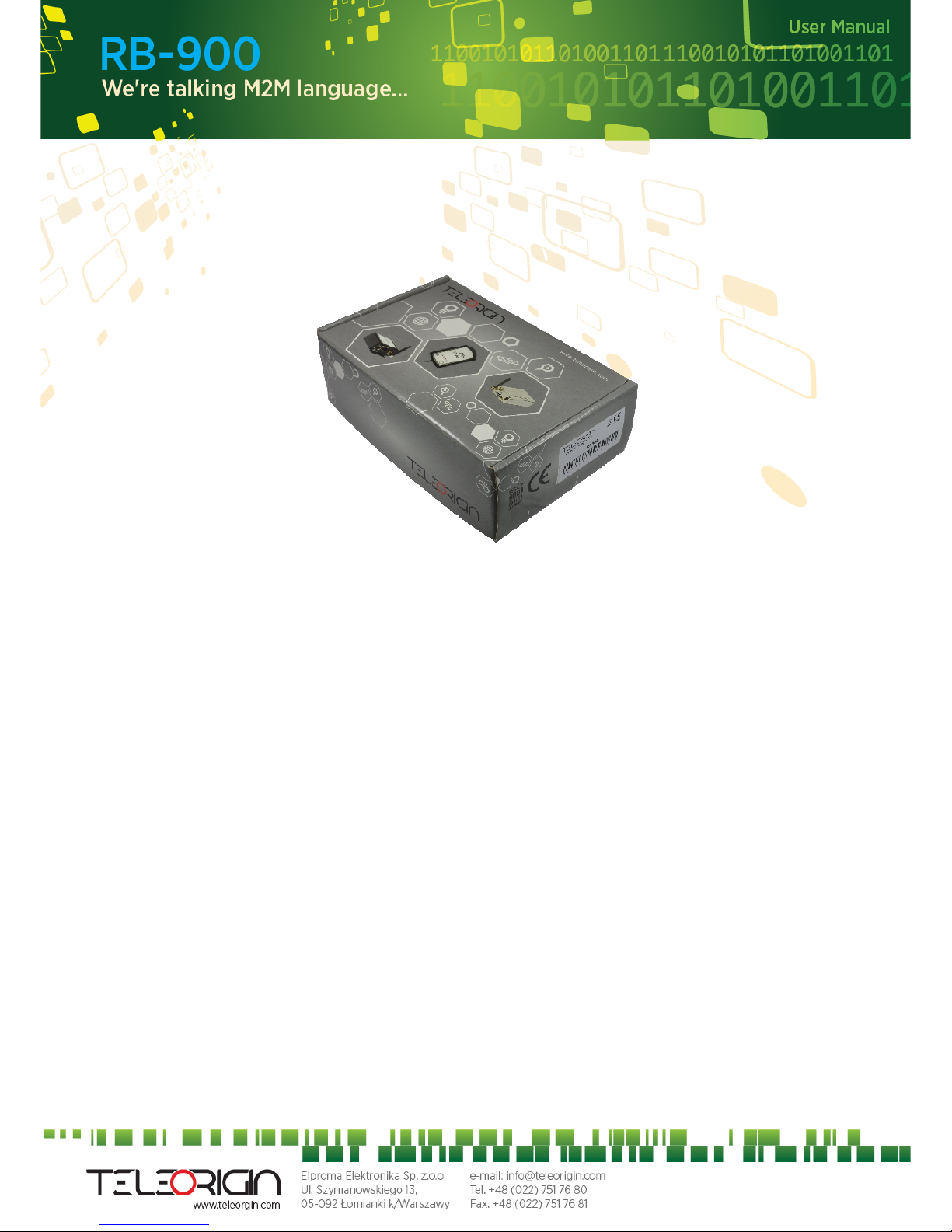
3.1 Box
Original box of the product is shown in the picture below.
We can find product sticker on the box. It matches modems sticker that is placed on the
device. This proves that your modem is original product. More information about stickers
in chapter 5.3.
7

4. Complete package contents
Complete package contains:
• RB900 terminal (item A)
• GSM antenna (via SMA) (item B)
• wall handle (item C)
• power adaptor (item D)
8
5. General presentation
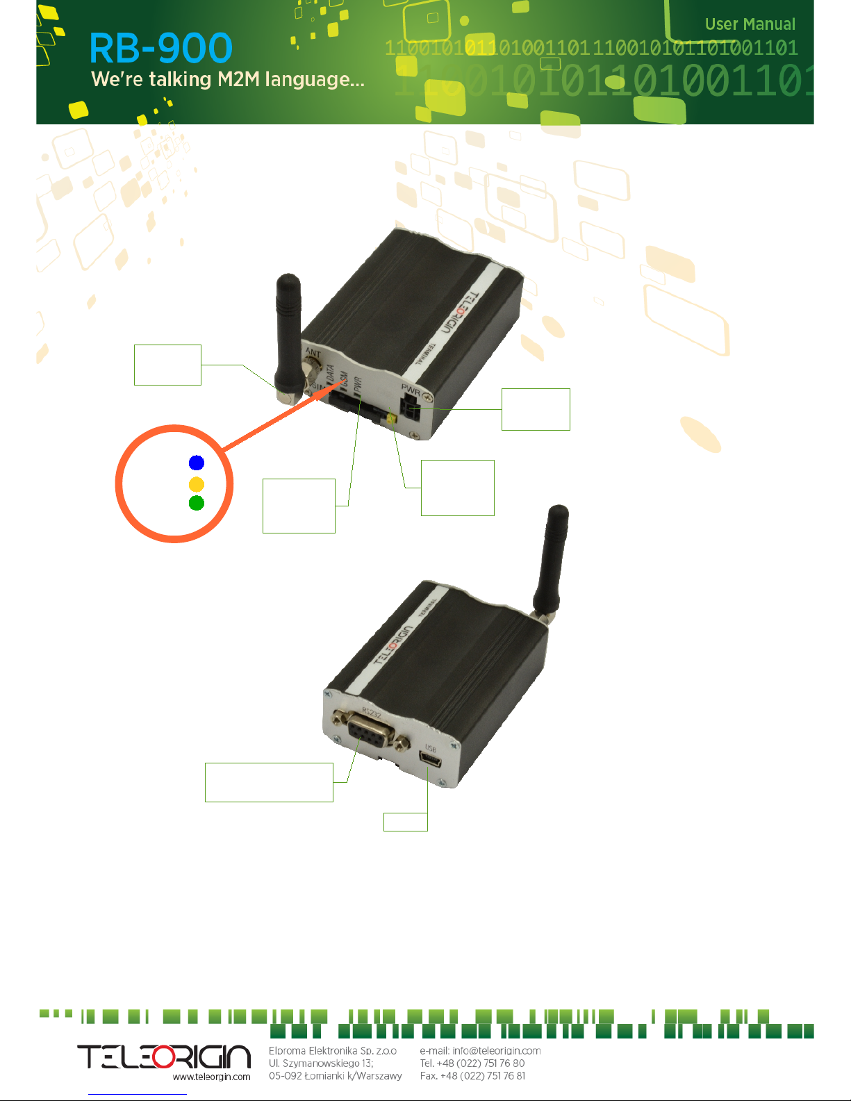
5.1 Product pictures
9
SMA
connector
Extractable
SIM card
holder
SIM card
holder
ejector
Power
supply
EIA574 (RS-232)
DE9 D-sub socket
USB
DATA
GSM
PWR
LED's
5.2 External connections
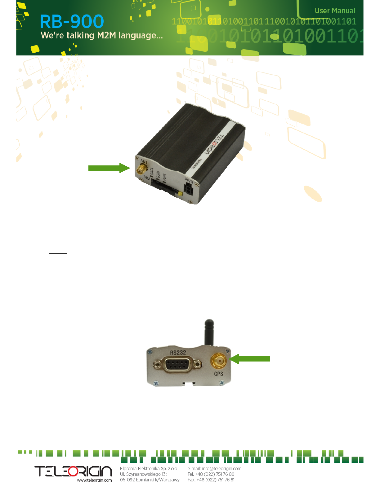
5.2.1 GSM antenna connector
SMA “ANT” input is used to connect external GSM antenna. To establish connection
with GSM network an external antenna must be used. Type of antenna depends on GSM
coverage. In good circumstances (level of received signal is high) use antenna which is
attached in the package. If range of GSM is low or none, an outdoor or indoor (for instance
in place where GSM range is sufficient) antenna should be used.
Note: If there is no antenna connected to SMA connector, the connection with GSM
network is impossible.
5.2.2 GPS antenna connector
SMA “GPS” input is used to connect external GPS antenna. To establish connection
with GPS sattelites and check the coordinates of device an external antenna must be used
and should be located outdoor.
10
5.2.3 Memory slot
RB900 can be optionally equipped with memory card slot to store all the measured
data. The slot type is microSD. Memory card can be controlled only by Python script using
special AT commands which is sends through SER2 interface, see chapter AT Reference
manual and Python Script Interpreter.
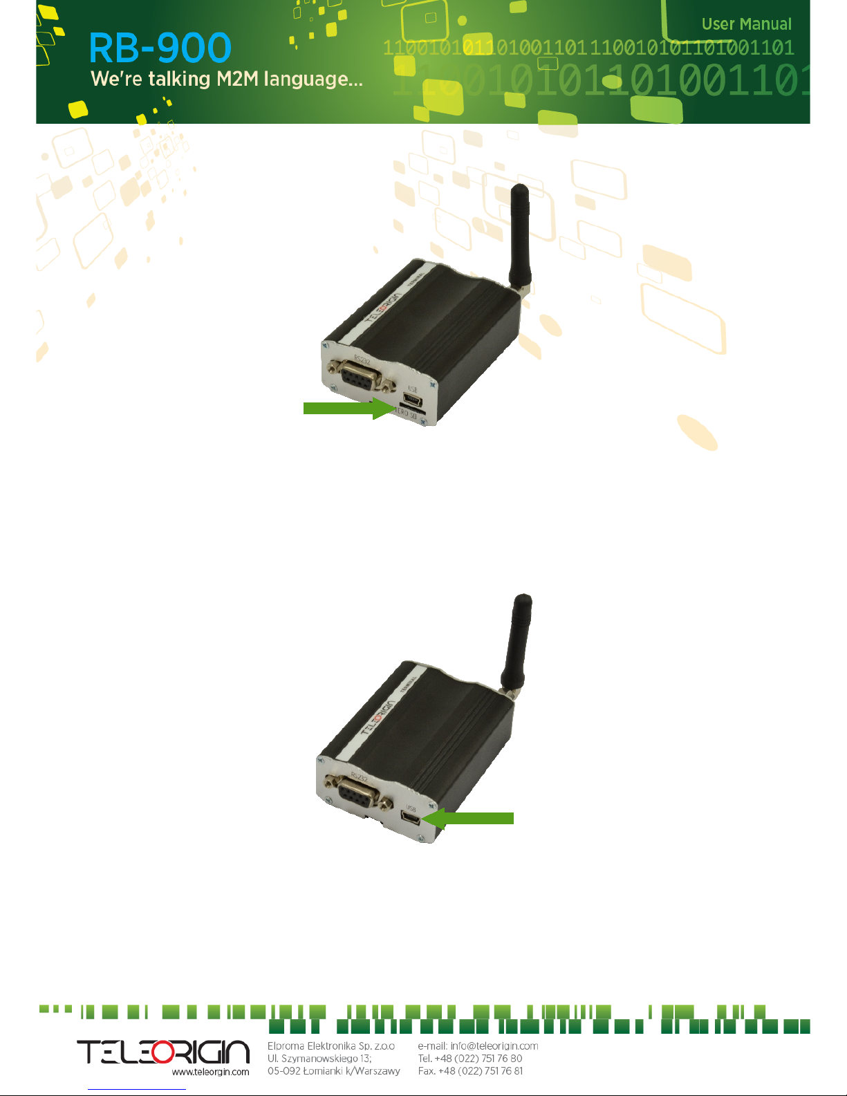
5.2.4 USB Interface
RB900 terminal is equipped with USB interface (as shown below) – miniUSB connector
type.
11
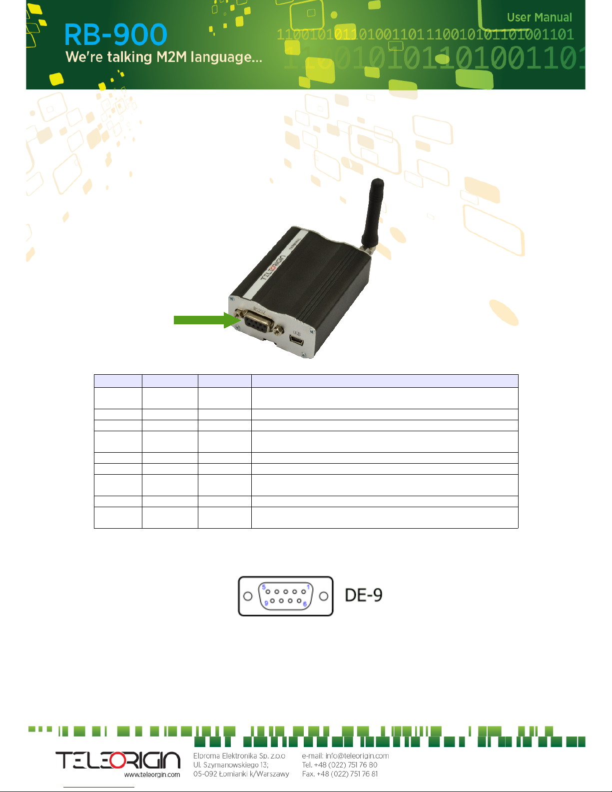
5.2.5 RS232 Interface (EIA574)
RB900 terminal is equipped with RS232 interface (as shown below). DE9 DSUB
socket is connected via voltage level translator circuit to the GSM module.
Table of RS232 DB9 pins:
Pin No. Name Dir Description
1 DCD IN Data Carrier Detect. Raised by DCE when modem
synchronized.
2 RD IN Receive Data (a.k.a RxD, Rx). Arriving data from DCE.
3 TD OUT Transmit Data (a.k.a TxD, Tx). Sending data from DTE.
4 DTR OUT Data Terminal Ready. Raised by DTE when powered on. In
auto-answer mode raised only when RI arrives from DCE.
5 SGND - Ground
6 DSR IN Data Set Ready. Raised by DCE to indicate ready.
7 RTS OUT Request To Send. Raised by DTE when it wishes to send.
Expects CTS from DCE.
8 CTS IN Clear To Send. Raised by DCE in response to RTS from DTE.
9 RI IN Ring Indicator. Set when incoming ring detected - used for auto-
answer application. DTE raised DTR to answer.
DE-9 (EIA/TIA 574)
looking into female connector
12
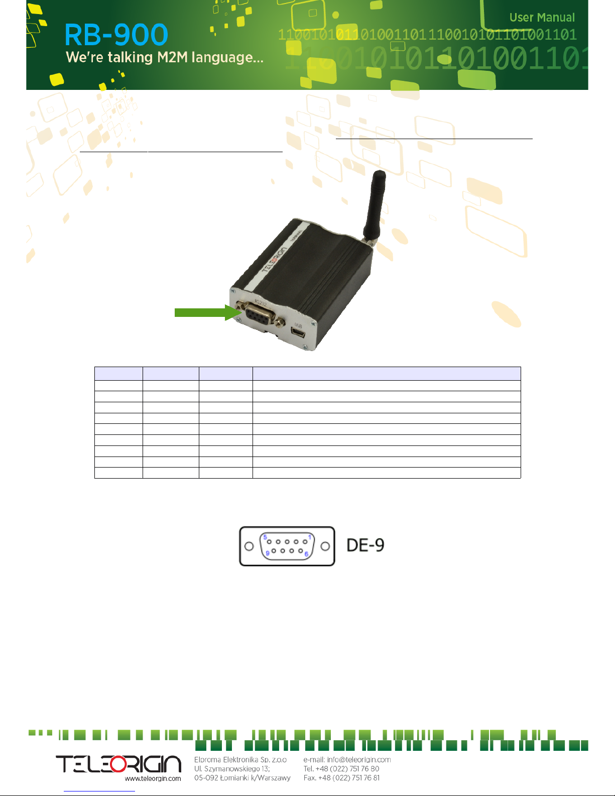
5.2.6 RS485 interface
RB900 terminal can be optionally equipped with RS485 half duplex interface (there can
be RS232 or RS485, not simultaneously ). DE9 DSUB socket is connected via voltage
level translator circuit to the GSM module.
Table of RS485 DB9 pins:
Pin No. Name Dir Description
1 NC - Not connected
2 NC - Not connected
3 NC - Not connected
4 NC - Not connected
5 GND - Ground
6 DATA+ IN/OUT
7 NC - Not connected
8 NC - Not connected
9 DATA- IN/OUT
DE-9 (EIA/TIA 574)
looking into female connector
13
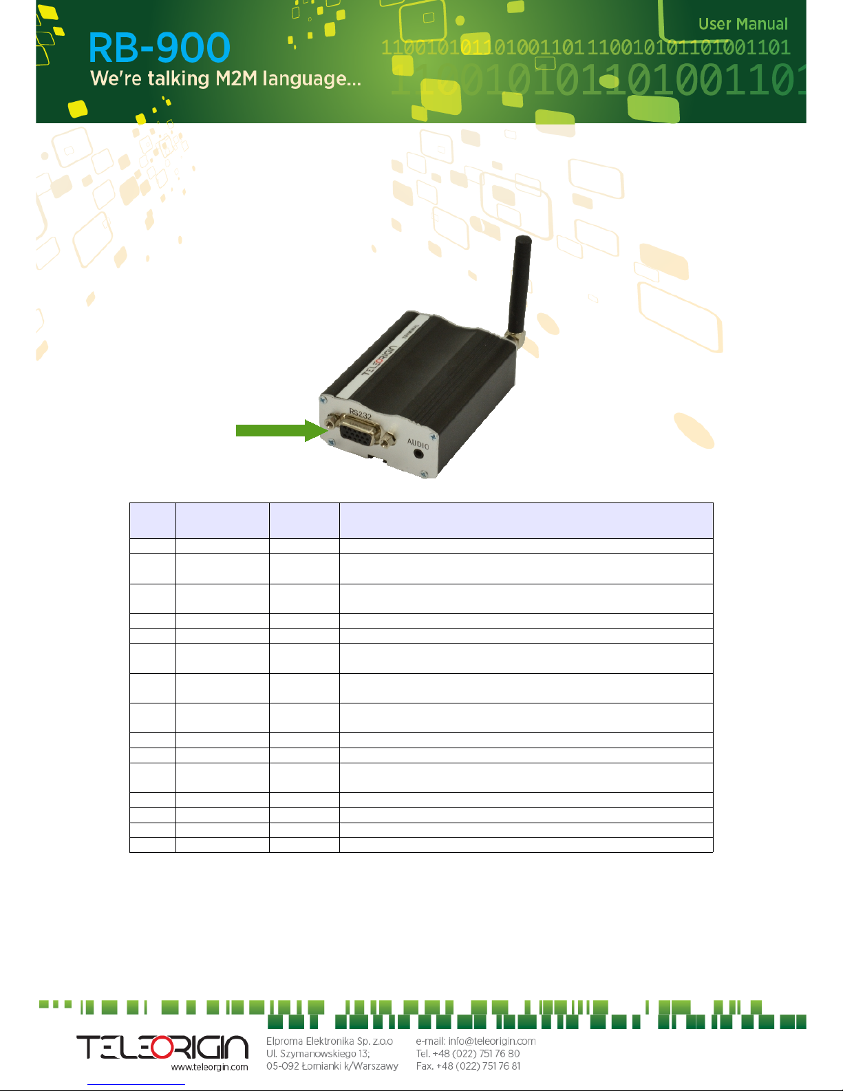
5.2.7 D-Sub HD 15-pin connector
RB900 can be equipped with DE9 15-pin connector to control RS232 interface and
GPIO lines. GPIO lines can be controlled by internal Python application, see Python Script
Interpreter for details. Below you can find pins description of this variant of modem.
Table of D-Sub HD 15- pin:
Pin
no.
Name Direction Description
1 GND - Ground
2 GPIO3 IN/OUT GPI3.3V, GPI 5-24V , GPO 5V, GPO
3.3V
3 GPIO8 IN/OUT GPI3.3V, GPI 5-24V , GPO 5V, GPO
3.3V
4 RTS IN Request To Send
5 TX OUT Transmit Data
6 GPIO5 IN/OUT OC, GPI3V3, GPI 5-24V , GPO 5V,
GPO 3.3V
7 GPIO6 IN/OUT GPI3.3V, GPI 5-24V , GPO 5V, GPO
3.3V
8 GPIO2 IN/OUT GPI3.3V, GPI 5-24V , GPO 5V, GPO
3.3V
9 DTR IN Data Terminal Ready
10 GND - GND
11 GPIO7 IN/OUT OC, GPI3V3, GPI 5-24V , GPO 5V,
GPO 3.3V
12 GPIO4 IN/OUT GPI3.3V, GPI 5-24V , GPO 5V, GPO 3.3V
13 GND - GND
14 RX IN Receive Data
15 CTS OUT Clear To Send
GPI3.3V – input, high state 3,3V
GPI5-24V – input, high state 5-24V
GPO3.3V – output, high state 3,3V
GPO5V – output, high state 3,3V
OC – output, open collector, 160mA, 30V
14
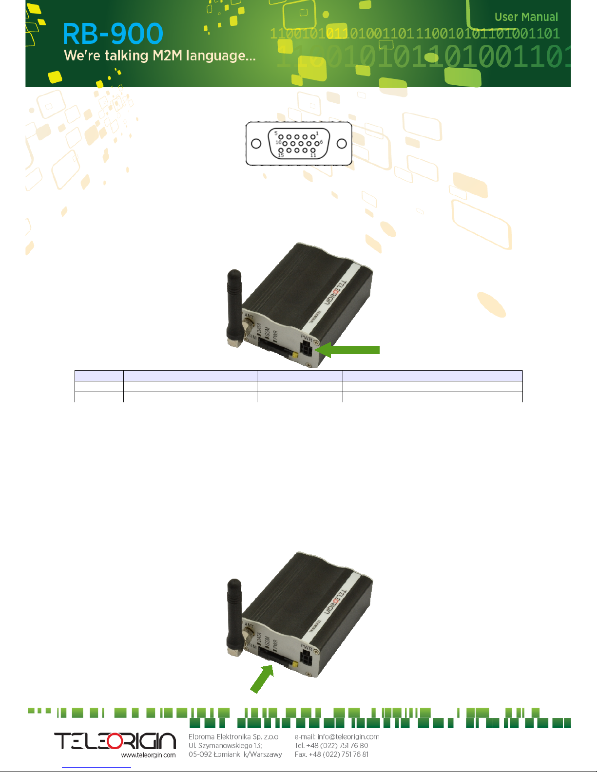
DE-15 looking into female connector:
5.2.8 Power supply connector
The power supply connector is a 2-pin connector for external DC power supply
connection, which can handle voltage from range 5..30 V DC, 2.5 W max. continuous
power.
No. Singal I/O Description
+ V+BATTERY I 5 V – 30 V DC
- GND - Ground
Attention!
An attempt to power terminal from DC source outside of 5..30 V range may result in
physical destruction of the device.
5.2.9 SIM card holder
SIM card holder is placed in front of RB900 terminal (as shown below) and is accessible
externally. To insert SIM card into the holder press the yellow button, eject the little
drawer, place there Your SIM card and insert drawer into the modem (You will hear click).
To operate the module in a GSM network, it is necessary to insert a SIM card obtained
from the network operator.
15
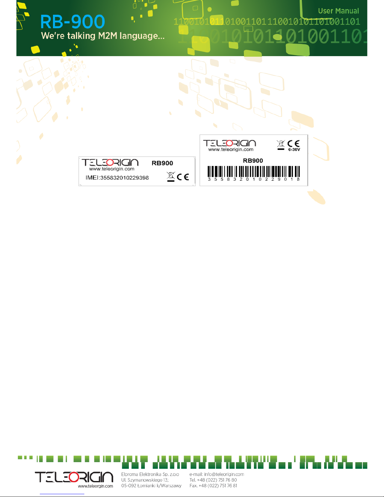
5.3 Product sticker
Product stickers are on the modem and on the box of the product.
A production sticker includes the following information:
• Product serial number (IMEI)
• the CE marking
• the 15-digit bar code
• the model signature (e.g. RB900)
Device sticker Box sticker
16
 Loading...