

Page 1
1
Contents
Page 2

2
1. Overview 4
2. References 5
3.Package 6
3.1 Box 6
4. Complete package contents 7
5. General presentation 8
5.1 Product pictures 8
5.2 External connections 9
5.2.1 GSM antenna connector 9
5.2.2 Bluetooth antenna connector 10
5.2.3 RS-232 Interface (EIA574) 11
5.2.4 Power supply connector 12
5.2.5 SIM card holder 13
5.3 Product sticker 14
6. Basic features and services 15
7. Using the modem 16
7.1 Setting up the modem 16
7.2 Mounting the modem on the wall 16
7.3 Checking the communication with the modem 17
7.4 Status of the modem (LEDs) 17
7.5 Disabling and enabling echo function 18
7.6 Verifying the strength of received signal 19
7.7 PIN code status 19
7.8 Network registration 20
7.8.1 GSM network registration 20
7.9 GPRS network registration 21
7.10 AT commands summary 22
8. Troubleshooting 23
8.1 No connection/communication with the modem 23
8.2 Receiving ERROR message 23
8.3 Receiving NO CARRIER message 24
9. Technical characteristics 25
9.1 Mechanical characteristic 25
9.2 Housing description (dimensioning diagram) 25
10. Electrical characteristic 26
10.1 Power supply 26
10.2 RF characteristics 26
10.3 External antenna 27
Page 3

3
10.4 Environmental characteristic 27
11. Safety recommendations 28
11.1 General Safety 28
11.2 Care and Maintenance 28
11.3 Responsibility 28
12. Conformity Assessment Issues 29
13. Safety Recommendations 30
14. List of Acronyms 31
15. On-line support 33
Page 4

4
Overview
The RB900-Pro terminal is the complete modem solution for wireless m2m applications.
Based on the high quality module, RB900-Pro offers high level GSM/UMTS/LTE Cat. 1,
GPIO and optional Dual SIM, MIMO, OneWire, GNSS receiver and internal battery
features in compact aluminum housing with all the standardized interfaces. Its small size
and wide supply voltage range, make it easy to integrate into all kinds of machines.
The RB900-Pro modem series, offering e-mail, TCP/UDP data transmission, SMS and
SMTP communication is a universal solution for all low-volume M2M and mobile data
applications including metering, traffic systems, transportation and logistics, security,
vending machines, and facility management.
The device can be controlled by standard AT commands or by customer's own
application, thus making it the smallest, most complete SMT platform for m2m solutions.
This document contains a full description of the RB900-Pro modem and gives
information about installation and use.
Page 5

5
References
[1] Quectel_EC25&EC21_AT_Commands_Manual_V1.1.pdf
Page 6

6
Package
Box
On the original box, you will find the product sticker. It should match modem sticker on
the device. This verifies that your modem is an original product. More information about
stickers in Product sticker.
Page 7
7
Complete package contents
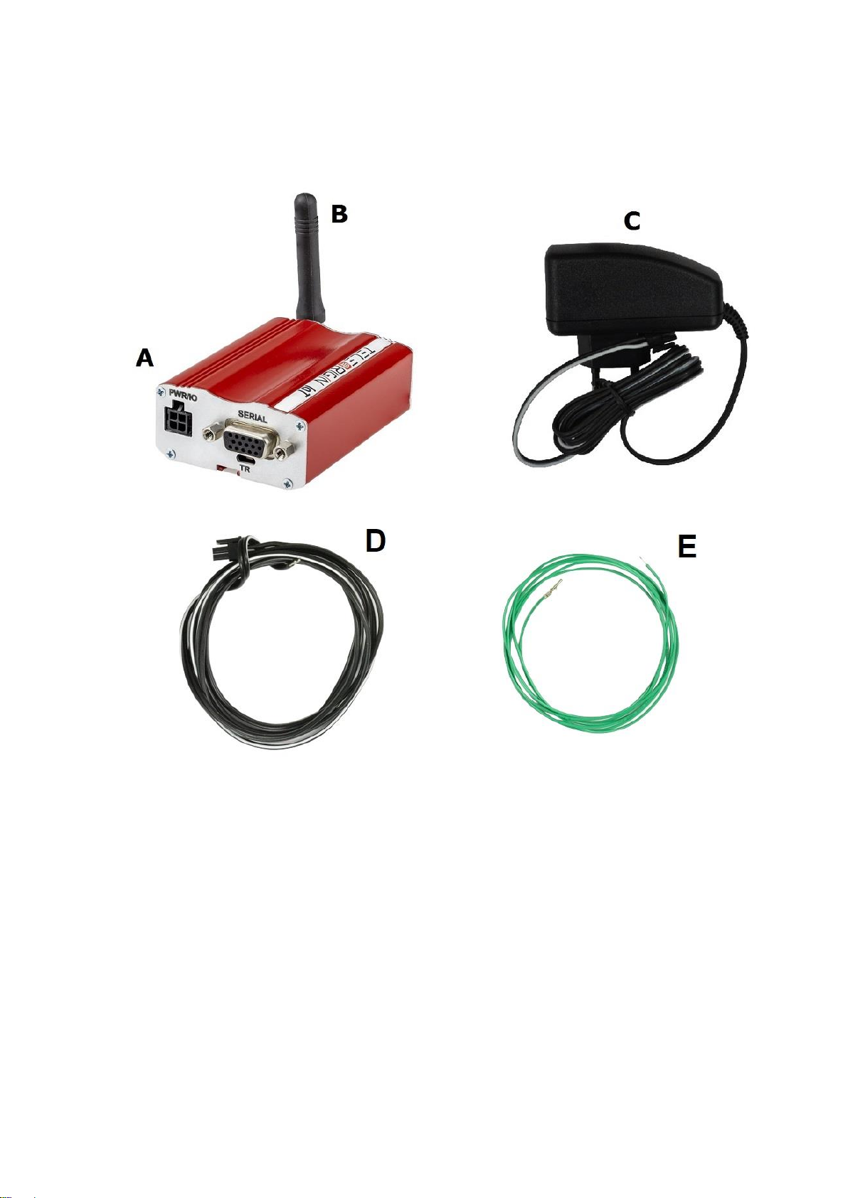
Complete package contains:
• RB900-Pro terminal (item A)
• antenna (item B)
• power supply with 4-pin (item C)
• 2-pin GPIO cable 1,5m open end (item D)
• 1-pin GPIO cable 1,5m open end (item E)
Page 8
8
General presentation
Product pictures
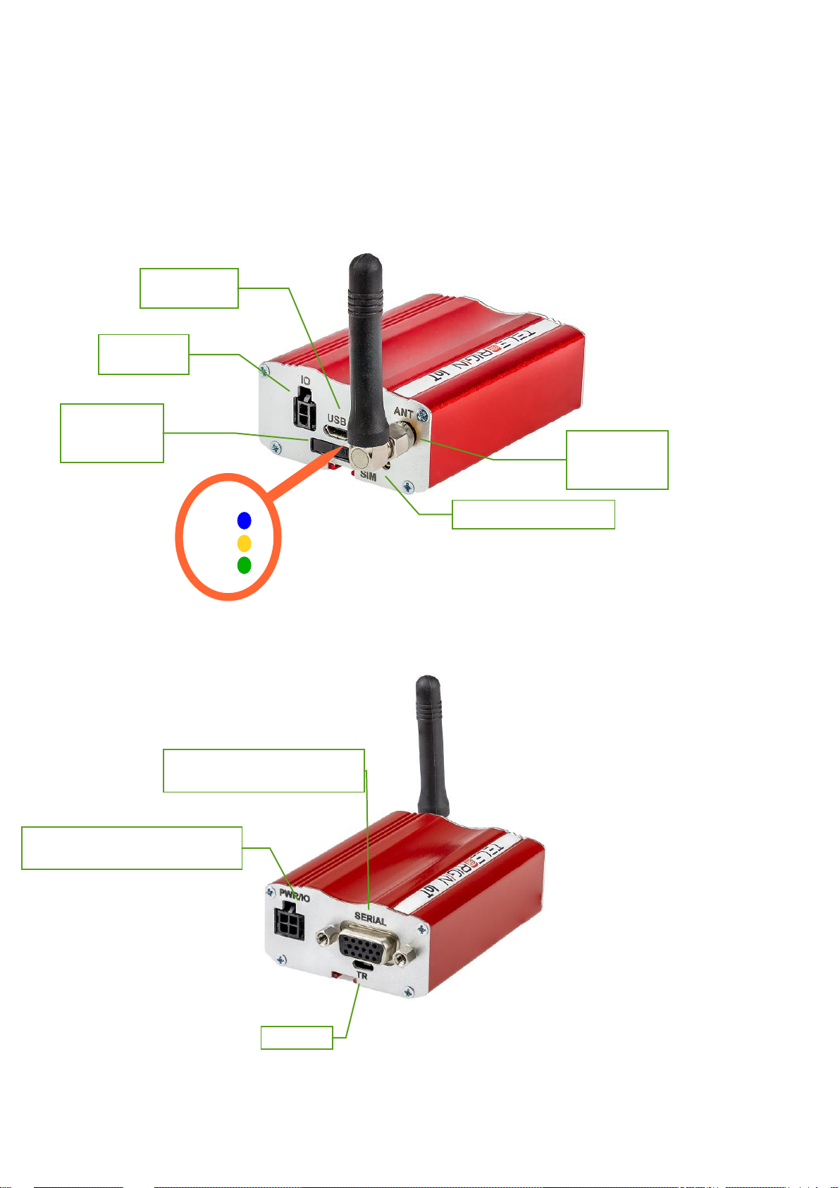
SMA antenna
connector
Extractable
SIM card
holder
SIM card holder ejector
TR switch
DATA
GSM
PWR
LEDs
Serial DE15 D-sub connector
Power supply and I/O connector
IO connector
USB interface
Page 9
9
External connections
GSM antenna connector
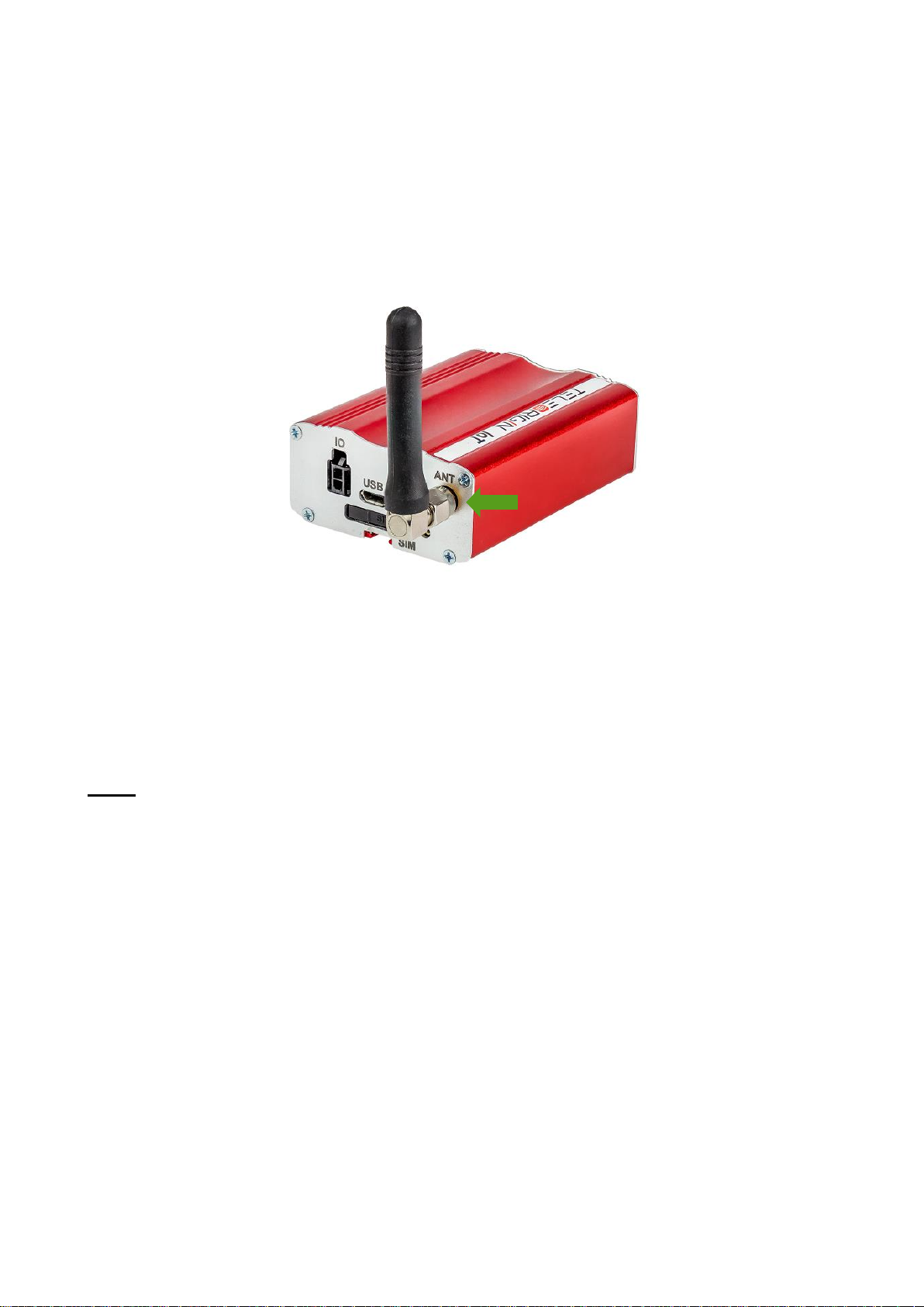
An SMA antenna input is used to connect an external GSM antenna. To establish a
connection with a GSM network, an external antenna must be used. Type of antenna
depends on the GSM coverage. In good circumstances (level of received signal is high)
use the antenna supplied in the package. If the range of GSM is low or none, an outdoor
or indoor (for instance in a place where GSM range is sufficient) antenna should be used.
Note: If there is no antenna connected to the SMA connector, connection with a GSM
network is impossible.
Page 10
10
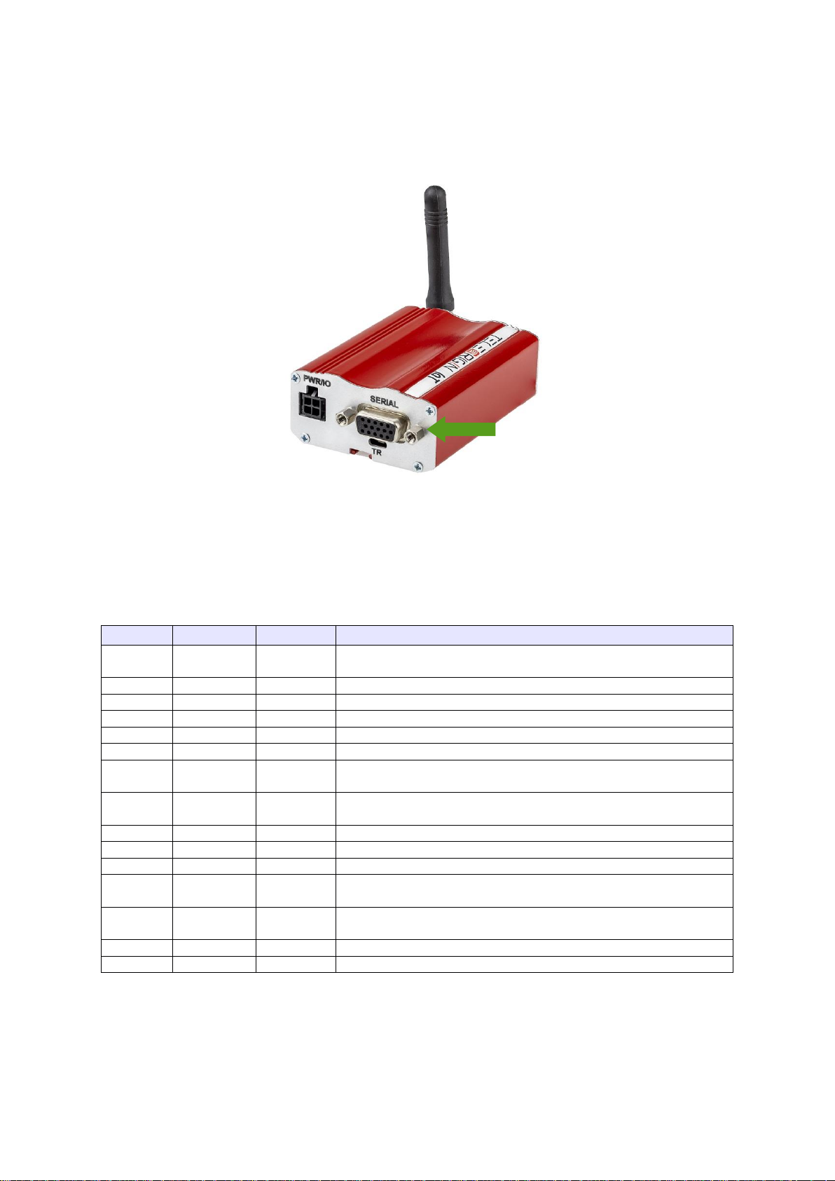
D-Sub 15-pin connector
The RB900-Pro terminal is equipped with a D-Sub DE15F 15-pin connector to control
the RS232 interface, RS232 AUX/Debug/MCU/Modem (option) or RS485 Modem/MCU
(option).
Table of DB9 pins:
Pin No.
Name
Dir
Description
1
DCD
OUT
Data Carrier Detect. Raised by DCE when modem
synchronized.
2
TXD
IN
Transmit Data (a.k.a TxD, Tx). Sending data from DTE.
3
Boot
Modem boot
4
NC
- - 5
NC
- - 6
RXD
OUT
Receive Data (a.k.a RxD, Rx). Arriving data from DCE.
7
DSR
OUT
Data Set Ready. Raised by DCE to indicate ready (optionally
RS485 A)
8
DTR
IN
Data Terminal Ready. Raised by DTE when powered on. In
auto-answer mode raised only when RI arrives from DCE.
9
GND
-
Ground
10
NC
- - 11
CTS
OUT
Clear To Send. Raised by DCE in response to RTS from DTE.
12
RTS
IN
Request To Send. Raised by DTE when it wishes to send.
Expects CTS from DCE.
13
RI
OUT
Ring Indicator. Set when incoming ring detected - used for auto-
answer application.
14
Reset
IN
Modem reset
15
NC*
-
Not connected in standard version*
* - Analog Input 0, 0-10V as an option
Page 11
11
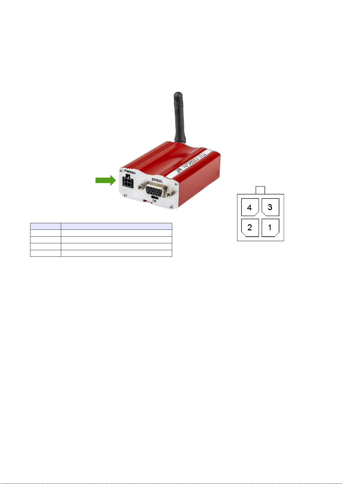
Power supply and I/O connector
The power supply and I/O connector is a 4-pin Micro Fit connector for external DC
power supply connection, which can handle voltage from range 5..30 V DC, 2.5 W max.
continuous power and one output (OC) and one Input.
No.
Singal
1
Output 1 (OC)
2
Not connected in standard version*
3
GND
4
V+
DC
* - Opto Input 1 as an option
Attention!
Any attempt to power on the terminal from a DC source outside of the 5 to 30
V range may result in physical destruction of the device.
NOTE: If the internal battery option is present, removing power supply will not turn the
terminal OFF.
Page 12
12
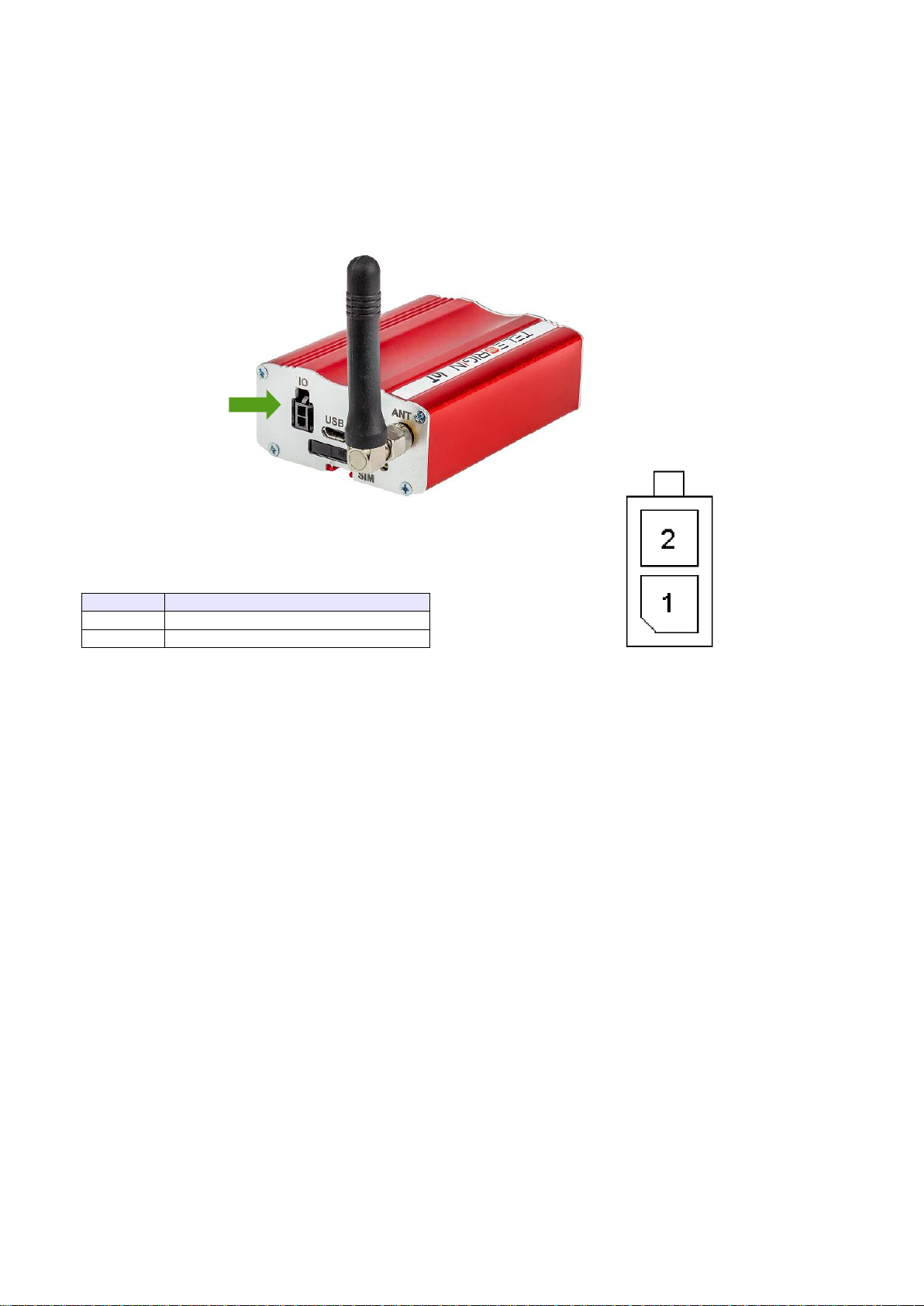
GPIO connector
The GPIO connector is a 2-pin Micro Fit connector for digital inputs. Pinout:
No.
Singal
1
GND*
2
1-Wire**
* Pin no. 1 on GPIO connector can be used as Opto Input 3 (option).
** Pin no. 2 can be used as Opto Input 2 or Analog Input 1 (option).
Page 13
13
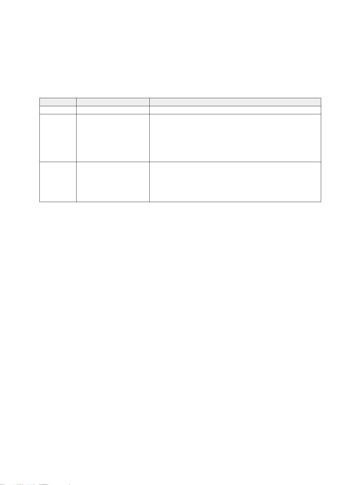
LED behaviour
The operational status of the RB900-Pro terminal is signalized by external LEDs placed
on the front panel of the modem. The status of all modem LEDs is described in the table
below.
LED
Color
Description
PWR
Green
Power supply
GSM
Yellow
Net status:
Flicker slowly (200ms High/1800ms Low) - Network
searching
Flicker slowly (1800ms High/200ms Low) - Idle
Flicker quickly (125ms High/125ms Low) - Data transfer
is ongoing
DATA
Blue
GSM GPIO 2 – controlled by user with AT command:
AT+QGPIOCFG=10,0,1,0,0
AT+QGPIO=0,10
AT+QGPIO=1,10,0 (LED OFF)
AT+QGPIO=1,10,1 (LED ON)
Page 14
14
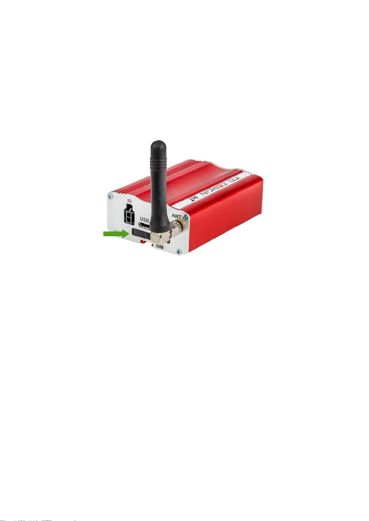
SIM card holder
SIM card holder is placed at the front of the RB900-Pro terminal (as shown below) and
is accessible externally. To insert a SIM card into the holder, press the yellow button,
eject the little drawer, place the SIM card inside and reinsert the drawer into the modem
(you will hear a “click”). To operate the module in a GSM network, it is necessary to insert
a SIM card obtained from the network operator.
Page 15
15
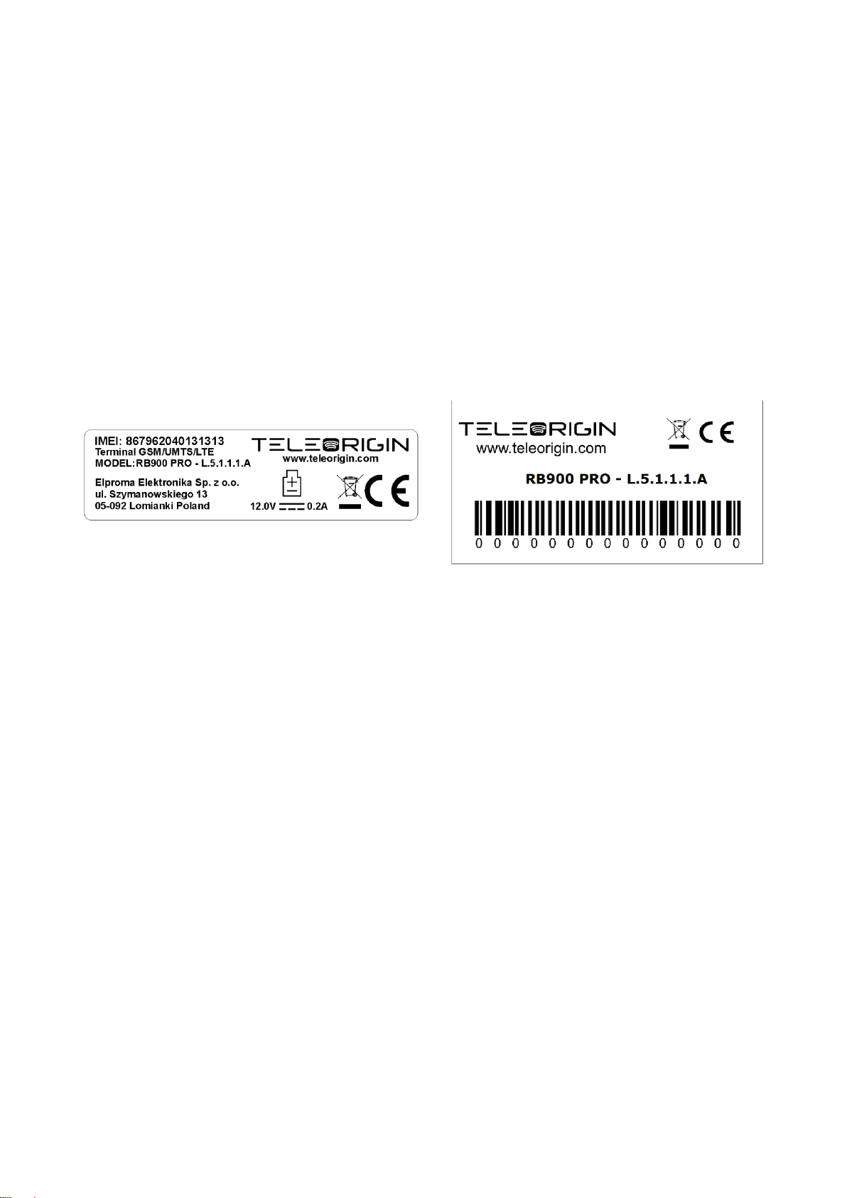
Product sticker
Product stickers are on the modem and on the product box. A production
sticker includes the following information:
⚫ product serial number (IMEI) and model signature
⚫ manufacturer address
⚫ the CE marking
⚫ the 15-digit bar code (box sticker only)
Device sticker Box sticker
Page 16

16
Basic features and services
Basic features and available services for the RB900-Pro are contained in the table below.
Feature/service
Description
Standard
Supported Bands:
LTE Cat. 1: B1/B3/B5/B7/B8/B20
WCDMA: B1/B5/B8
GSM: Dual-band B3/B8
Physical:
• 83 x 53,5 x 25 mm
• Weight 89 g
Speed
LTE: Max. 10Mbps (Downlink) / Max. 5Mbps (Uplink)
WCDMA: Max. 384Kbps (Downlink) / Max. 384Kbps (Uplink)
EDGE: Max. 296Kbps (Downlink) / Max. 236.8Kbps (Uplink)
GPRS: Max 107Kbps (Downlink) / Max. 85.6Kbps (Uplink)
Interfaces
• USB 2.0 with High Speed up to 480Mbps
• RS232 on 15-pin D-Sub female connector
• RS485
• GPIO
• 1-Wire (check )
• OneWire (optional)
• GNSS receiver (optional)
• Internal battery (optional)
Connectors
• GSM/LTE SMA-Female
• LTE Diversity SMA-Female (optional)
• GNSS receiver SMA-Female (optional)
SIM Card
• 3.0V / 1.8V
• STK 3.1
Sensitivity
• LTE B1: -101.5dBm (10M), LTE B2: -101dBm (10M), LTE B3: -
101.5dBm (10M), LTE B4: -101dBm (10M), LTE B5: -101dBm
(10M), LTE B7: -99.5dBm (10M), LTE B8: -101dBm (10M), LTE
B12: -101dBm (10M), LTE B13: -100dBm (10M), LTE B20: -
102.5dBm (10M), LTE B28: -102dBm (10M),
• WCDMA B1: -110dBm, WCDMA B2: -110dBm, WCDMA B4: -
110dBm, WCDMA B5: -110.5dBm, WCDMA B8: -110.5dBm
• GSM: -109dBm
• DCS: -109dBm
SMS
• MO / MT Text and PDU mode
Power supply
5V – 30V DC
Page 17

17
Using the modem
Setting up the modem
To set the modem up, follow these steps:
• Eject SIM card holder using the yellow button and pull out the drawer.
• Insert your SIM card into the drawer.
• Verify if the SIM card fits in the drawer properly.
• Insert the drawer into the modem. Connect the antenna to the SMA connector
• Optionally, the modem can be connected using RS232 or USB interface
• Plug the power supply cable into the power supply input
• Now the modem is ready to work.
Installing USB drivers
Before you connect the device to the USB interface, you need to install the drivers.
They can be downloaded using the links below:
Windows: setup.exe
Linux: README
Page 18

18
Checking the communication with the modem
Once the modem is connected you can check RS232 or USB communication between
the RB900-Pro and the PC using any Terminal program. Configuration of the DTE (port
COM) could be as follows:
• Bits per second: 115200 bps,
• Data bits: 8,
• Parity: None,
• Stop bits: 1,
• Flow control: hardware.
Using a communication software such as Hyperterminal, enter the AT and push 'enter'
button. The response of the terminal should be 'OK' displayed in the Hyperterminal
window.
If the connection with the modem cannot be established do the following:
• Check if modem is connected with PC via RS-232 or USB.
• Check the configuration of the COM port.
Examples of AT commands:
• ATE1 enables modem echo function,
• AT+CPIN? shows current status of SIM card
• AT+CPIN=xxxx to enter PIN, where 'xxxx' are digitals
• AT+CSQ to verify received signal strength
• ATD<phone_number>; to initiate a voice call
• ATH to hang up a voice call
For further information about AT commands and their usage, refer to [1].
Disabling and enabling echo function
If echo is not displayed when entering AT command, that means:
• The local echo function in software (such as Hyperterminal) is disabled
• The echo function of the modem is disabled
To enable echo function of the modem enter the ATE1 command.
In Machine to Machine communication it is recommended to disable echo function (type
ATE0) in order to avoid unnecessary CPU usage.
For further information about AT commands and their usage, refer to [1].
Page 19
19
Verifying the strength of received signal
RB900-Pro terminal can establish a connection with network if the received signal
strength is sufficiently strong. To verify the signal strength and bit error rate, do the
following:
using software such as Hyperterminal enter AT+CSQ. This command displays the
received signal strength indication <rssi> and channel bit error rate <ber>. The modem
answers as follows:
+CSQ: <rssi>,<ber>
OK
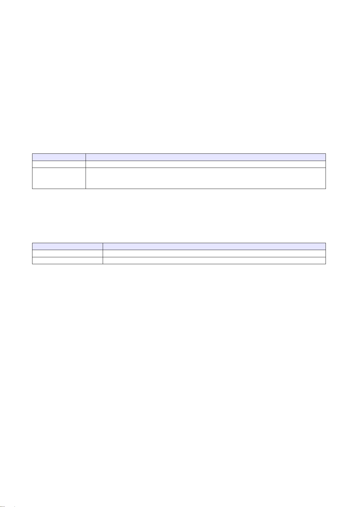
<parameter>
Description
<rssi>
0 through 31 - covers the range of -113 dbm (or less) to -51dbm (or greater)
<ber>
Channel bit error rate (in percent)
0–7 RXQUAL values in the GSM 05.08 table
99 Unknown or not detectable
For further information about AT commands and their usage, refer to [1].
PIN code status
To check the PIN code status enter AT+CPIN? Command.
The table below shows the relevant main responses of the modem:
Answer
Description
+CPIN: SIM PIN
PIN code has not been entered
+CPIN: READY
PIN code has been entered correctly
For further information about AT commands and their usage, refer to [1].
Page 20
20
Network registration
GSM network registration
To check GSM network registration status enter AT+CREG? into the software (for
instance Hyperterminal). The modem will answer in following format:
+CREG: <n>,<stat>[,<lac>,<ci>]
OK
The following table shows the +CREG parameters:
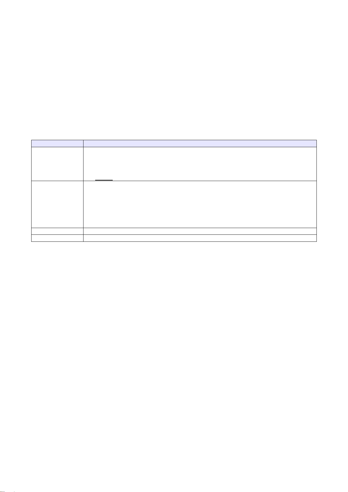
<parameter>
Description
<n>
0 Disables the network registration unsolicited result code.
1 Enables the network registration unsolicited result code +CREG: <stat>.
2 Enables the network registration and location information in unsolicited
reports and Read command +CREG:<stat>[,<lac>,<ci>].
The default is 0.
<stat>
0 Not registered, and the ME is not currently searching for a new operator to which to
register.
1 Registered, home network.
2 Not registered, but the ME is currently searching for a new operator to which to register.
3 Registration denied.*
4 Unknown.
5 Registered, roaming.
<lac>
Two-byte location area code in hexadecimal format
<ci>
Two-byte cell ID in hexadecimal format.
*To manage connecting to a network, the SIM card inserted into the modem must be valid.
For further information about AT commands and their usage, refer to [1].
Page 21
21
AT commands summary
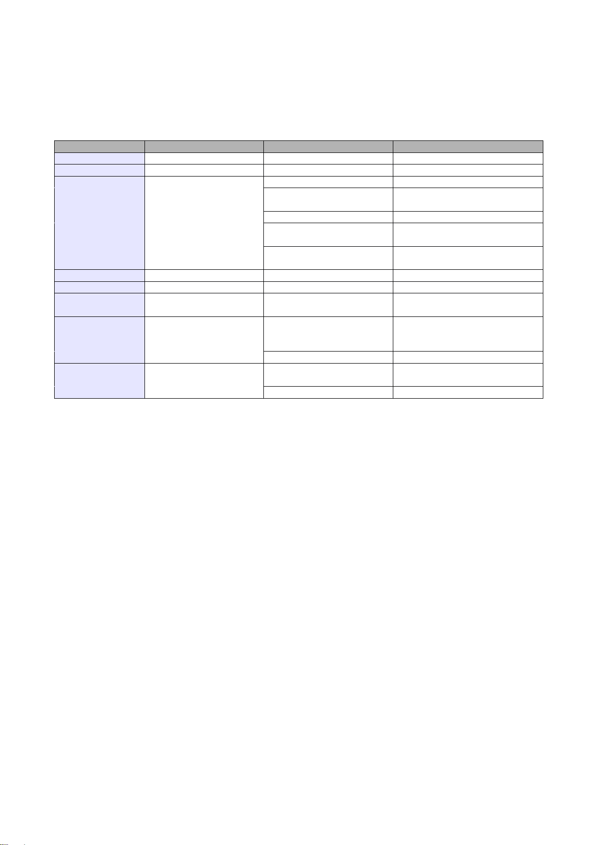
As a conclusion, the table below shows the most common and useful AT commands.
For more AT commands refer to [1].
Action
Syntax
Response
Comments
Echo enable
ATE1
OK
Typed text is seen.
Echo disable
ATE0
OK
Typed text is not seen.
Voice call
ATD<phoneNo>;
OK
Call initiated.
Remember of ';'
NO CARRIER/BUSY/NO
ANSWER
Connection failure.
+CME ERROR: <err>
General error*
OPERATION NOT
ALLOWED
Security reason (such as SIM
card not inserted)
UNKNOWN CALLING
ERROR
Unknown reason
Hung up call
ATH
NO CARRIER
Connection is hanged up.
Receiving call
ATA
OK
Call is answered.
Communication
loss
NO CARRIER
Enter PIN code
AT+CPIN=[<puk>
or <pin>],
[<newpin>]
OK Set PIN or PUK or new PIN
code.*
+CME ERROR: <err>
General error*
Check PIN code
status
AT+CPIN?
+CPIN: <code>
OK
Returns status of PIN.
e.g. READY or SIM PIN
+CME ERROR: <err>
General error*
*Refer to [1].
Page 22

22
QuecOpenTM (Linux)
Quectel QuecOpenTM is an open embedded platform that is built on the Linux system. It is
designed to simplify the development for IoT (Internet of Things) applications. A description of the
platform can be found in this document: QuecOpen_Linux.pdf
Page 23

23
Troubleshooting
No connection/communication with the modem
If there is no communication with the modem do the following steps:
• Check all external connections of the modem (RS-232 or USB, power supply)
• Verify if the power supply is correct (see Power supply)
• Check if the COM port is correctly parametrized
• Check if the program used for communication works properly and if there is no
other program interfering. If yes, close the interfering program.
Receiving ERROR message
Modem answers ERROR on AT command in following cases:
• Syntax of typed AT command is incorrect – check the command syntax in [1]
• Parameters of typed AT command are incorrect – type AT+CMEE=1 for enabling a
description of the error that occurred. The response now will be in this format:
ERROR
+CME ERROR: <err>
where <err> is a description of the error that occurred
• Refer to [1] for further details about the occurred error
Page 24
24
Receiving NO CARRIER message
There are some common cases when modem answers NO CARRIER:
• If data/voice/fax connection cannot be established
• Right after hanging up the data/voice/fax connection
• If there is no connection with network – check antenna and registration status (see
Network registration)
• If there is no power supply (see Power supply)
If the modem answers NO CARRIER in some cases, you can have an extended error
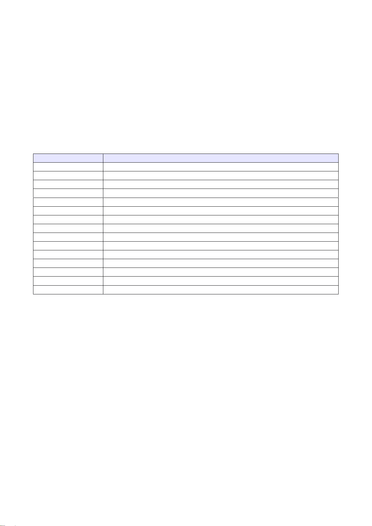
code using AT+CEER. The table below shows some of codes which can appear.
Error code
Description
1
Unassigned or unallocated number
3
No route to destination
6
Channel unacceptable
8
Operator determined barring
16
Normal call clearing
17
User busy
18
No user responding
19
User alerting, no answer
21
Call rejected
22
Number changed
27
Destination out of order
28
Invalid number format (incomplete number)
34
No circuit/channel available
38
Network out of order
41
Temporary failure
For further information about AT commands and their usage, refer to [1].
Page 25
25
Technical specification
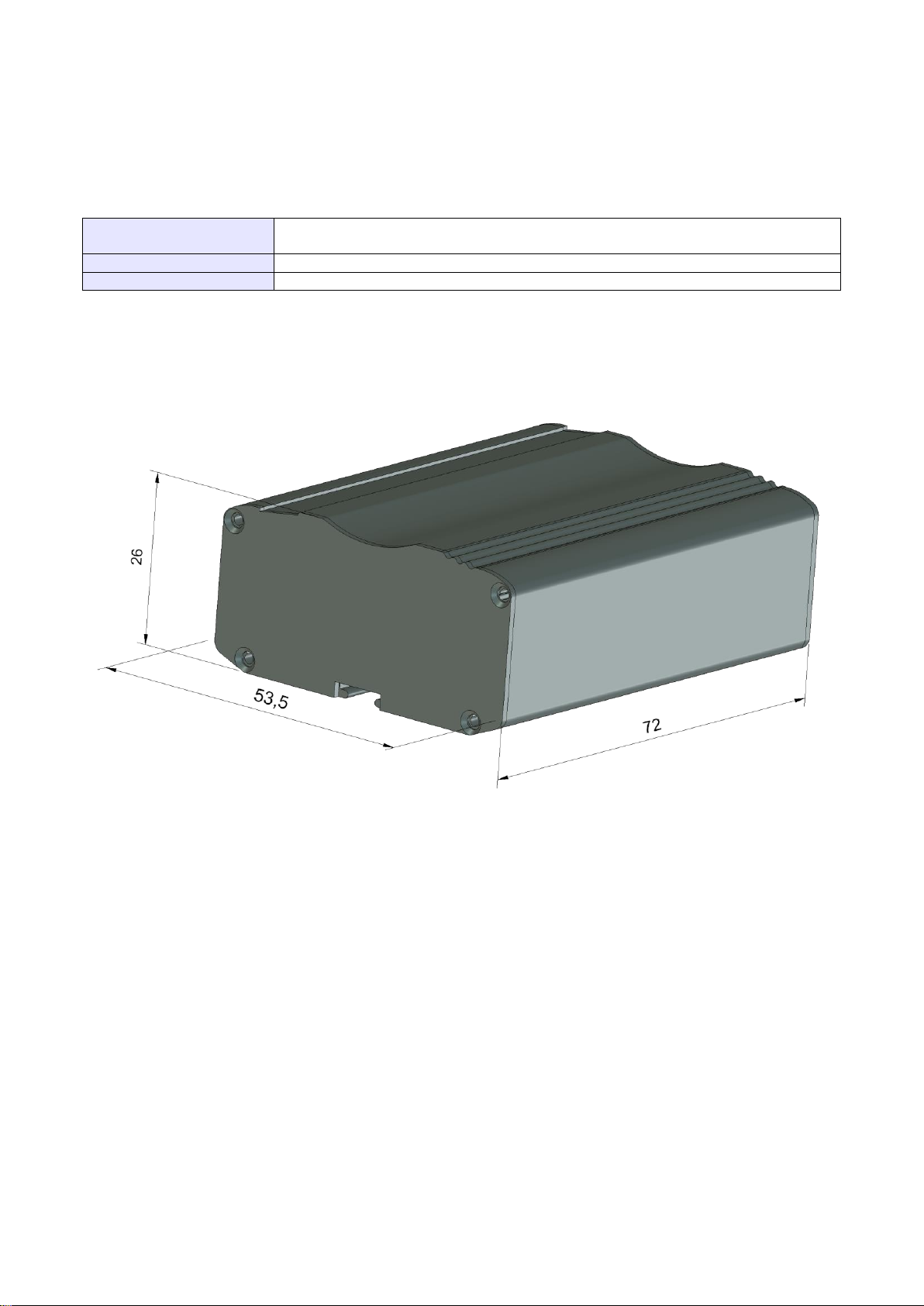
Mechanical specification
Max. dimensions
72 x 53.5 x 26 mm (w/o connectors)
83 x 53.5 x 26 mm (w/ connectors)
Weight
≈ 89 g
Volume
100 cm3 (w/o connectors)
Housing diagram
Page 26

26
Electrical specifications
Power supply
• Nominal voltage range: 5..30 V, 10%
• Maximum continuous (average) supply power: 2.5 W
• Maximum continuous (average) supply current: 200 mA at 12V
Page 27
27
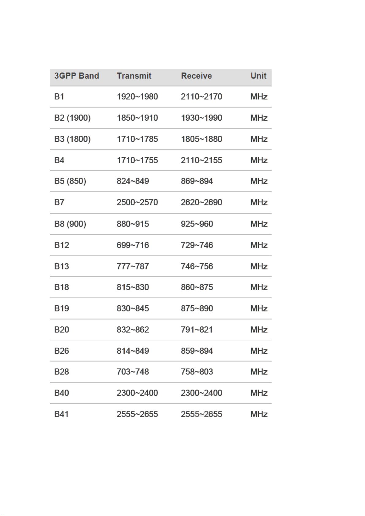
RF specifications
Page 28
28
External antennas
The external GSM antenna is connected to the modem via an SMA connector.
The antenna must have parameters listed below in the table.
Antenna frequency range
LTE (699-960MHz / 1710-2690MHz)
Impedance
50 Ω
DC impedance
0 Ω
Gain
0 dBi w/o cable; 2dBi w/ cable
VSWR (with cable)
-10 dB
The choice of antenna for the modem should best fit the environment it is used in. When
the modem is placed in a room or somewhere where the range of networks signal is too
low, the outdoor or specific indoor antenna should be used to boost it.
Environmental specification
The table below gives the environmental operating conditions of the RB900-Pro
terminal.
Attention!
Exceeding the values may result in permanent damage to the module.
Parameter
Conditions
Min
Max
Unit
Ambient Operating
Temperature
-20
60
°C
Storage Temperature
-40
85
°C
ESD
At antenna connector
Contact
Air
At interface connector
± 6
± 15
± 1
KV
Humidity
5
85
%
Page 29

29
Safety recommendations
General Safety
Please follow safety regulations regarding the use of radio equipment due to the
possibility of radio frequency interference. Please read the advice carefully.
Switch off GSM terminal when:
• in an aircraft – using cellular telephones in aircraft may endanger the operation of
the aircraft; it is illegal
• at a refuelling point
• in any area with a potentially explosive atmosphere which could cause an explosion
or fire
• in hospitals and any other places where medical equipment is in use
Respect restrictions on the use of radio equipment in any area or place where it is
signed that using cellular telephones is forbidden or dangerous.
Using the GSM modem close to other electronic equipment may also cause interference
if the equipment is inadequately protected. It may lead to damage or failure of GSM
modem or the other equipment.
Care and Maintenance
The RB900-Pro terminal is an electronic product that should be treated with care.
Please follow the suggestions below to ensure your modem has a long life.
• Do not expose the RB900-Pro to any extreme circumstances like high temperature
or high humidity
• Do not keep modem in dirty and dust places
• Do not dismantle the RB900-Pro modem
• Do not expose the modem to any water, rain or steam
• Do not drop, shake or knock your modem
• Do not place your modem close to magnetic devices – credit cards, etc
• Use of third party equipment or accessories, not made or authorized by Elproma
Electronika Sp. z o.o. may invalid the warranty of modem and/or cause failure or
permanent damage to the modem
• Do not expose the modem to children under 3 years
Responsibility
The modem is your responsibility. Please treat it with care, and respect local
regulations. This is not a toy – keep it out of the reach of children.
Try to use security features (PIN etc.) to block unauthorized use or theft.
Page 30

30
Conformity Assessment Issues
The RB900-Pro has been assessed in order to satisfy the essential requirements of the
RED 2014/53/EU to demonstrate the conformity against the harmonised standards with
the final involvement of a Notified Body.
Page 31

31
Safety Recommendations
READ CAREFULLY
Be sure the use of this product is allowed in the country and in the environment
required. The use of this product may be dangerous and has to be avoided in the following
areas:
• where it can interfere with other electronic devices in environments such as
hospitals, airports, aircrafts, etc
• where there is a risk of explosion such as gasoline stations, oil refineries, etc
It is responsibility of the user to enforce the country regulations and the specific
environment regulations.
Do not dismantle the product; any sign of tampering will compromise the warranty
validity.
We recommend following the instructions of the hardware user guides for the correct
wiring of the product. The product has to be supplied with a stabilized voltage source and
the wiring has to conform to the security and fire prevention regulations.
The product has to be handled with care, avoiding any contact with the pins because
electrostatic discharges may damage the product itself. The same precautions have to be
taken with the SIM, carefully check the instructions for its use. Do not insert or remove the
SIM when the product is in power saving mode.
The system integrator is responsible of the functioning of the final product; therefore,
care has to be taken of the external components of the module, as well as of any project or
installation issue, because the risk of disturbing the GSM network or external devices or
having impact on security. Should there be any doubt, please refer to the technical
documentation and the regulations in force.
Every module has to be equipped with a proper antenna with specific parameters. The
antenna has to be installed with care in order to avoid any interference with other
electronic devices and has to guarantee a minimum distance from people (20 cm). In case
of this requirement cannot be satisfied, the system integrator has to assess the final
product against the SAR regulation.
Page 32

32
List of Acronyms
ACM
Accumulated Call Meter
ASCII
American Standard Code for Information Interchange
AT
Attention commands
CB
Cell Broadcast
CBS
Cell Broadcasting Service
CCM
Call Control Meter
CLIP
Calling Line Identification Presentation
CLIR
Calling Line Identification Restriction
CMOS
Complementary Metal-Oxide Semiconductor
CR
Carriage Return
CSD
Circuit Switched Data
CTS
Clear To Send
DAI
Digital Audio Interface
DCD
Data Carrier Detected
DCE
Data Communications Equipment
DRX
Data Receive
DSR
Data Set Ready
DTA
Data Terminal Adaptor
DTE
Data Terminal Equipment
DTMF
Dual Tone Multi Frequency
DTR
Data Terminal Ready
EMC
Electromagnetic Compatibility
ETSI
European Telecommunications Equipment Institute
FTA
Full Type Approval (ETSI)
GPRS
General Radio Packet Service
GSM
Global System for Mobile communication
HF
Hands Free
IMEI
International Mobile Equipment Identity
IMSI
International Mobile Subscriber Identity
IRA
Internationale Reference Alphabet
ITU
International Telecommunications Union
IWF
Inter-Working Function
LCD
Liquid Crystal Display
LED
Light Emitting Diode
LF
Linefeed
ME
Mobile Equipment
MMI
Man Machine Interface
MO
Mobile Originated
MS
Mobile Station
MT
Mobile Terminated
OEM
Other Equipment Manufacturer
PB
Phone Book
PDU
Protocol Data Unit
PH
Packet Handler
PIN
Personal Identity Number
PLMN
Public Land Mobile Network
PUCT
Price per Unit Currency Table
PUK
PIN Unblocking Code
RACH
Random Access Channel
Page 33

33
RLP
Radio Link Protocol
RMS
Root Mean Square
RTS
Ready To Send
RI
Ring Indicator
SAR
Specific Absorption Rate (e.g. of the body of a person in an electromagnetic field)
SCA
Service Center Address
SIM
Subscriber Identity Module
SMD
Surface Mounted Device
SMS
Short Message Service
SMSC
Short Message Service Center
SPI
Serial Protocol Interface
SS
Supplementary Service
TIA
Telecommunications Industry Association
UDUB
User Determined User Busy
USSD
Unstructured Supplementary Service Data
Page 34

34
On-line support
Elproma provides a range on on-line support which includes:
• the latest version of this document
• the latest drivers for RB900-Pro
• technical support
This information can be found on our web sites at www.teleorigin.com
For further information you can contact us at:
Page 35

35
 Loading...