

Page 1

Telecell Installation Manual
CDox Original Author: Catherine Wijman
Other Authors: [free text field]
CDox Latest Issuer: Catherine Wijman
Issue Date: 2018-02-08
Document Ref: TL-006175-PR
Issue 5
Telecell Installation Manual Introduction
TL-006175-PR Issue 5 © Telensa Ltd 2018 Page 1
Page 2

Notices
This document is provided to you by or on behalf of Telensa Ltd.
© Telensa Ltd 2018.
The documentation and any software described herein and/or provided to you in
conjunction with this documentation contain proprietary and confidential information of
Telensa Ltd and may only be used subject to a license agreement containing restrictions
on use and disclosure. They are also protected by copyright, patent rights and other
intellectual and industrial property laws. The information contained in this document and
any software described herein is subject to change without notice. If you find any
problems in the documentation and/or the software, please report them to us in writing.
The document and/or the software are not warranted to be error-free. No right, title,
license or interest in any physically or electronically distributed materials is transferred to
you by such distribution. No part of this document and/or the software may be
reproduced, displayed, copied, translated, adapted, downloaded, electronically
transmitted, used or reproduced in any form including (without limitation) distribution or
storage in a system for retrieval without our express written permission (which may be
subject to conditions).
The documentation and/or software may provide links to Web sites and access to
content, products, and services from third parties. Telensa Ltd is not responsible for the
availability of, or any content provided on, third-party Web sites. You bear all risks
associated with the use of such content. If you choose to purchase any products or
services from a third party, the relationship is directly between you and the third party.
Telensa Ltd is not responsible for: (a) the quality of third-party products or services; or
(b) fulfilling any of the terms of the agreement with the third party, including delivery of
products or services and warranty obligations related to purchased products or services.
Telensa Ltd is not responsible for any loss or damage of any sort that you may incur
from dealing with any third party.
Telensa Ltd is the owner of the “Telensa” trademark and all associated trade names,
logos and devices unless indicated to the contrary. Any other trademarks, logos and
names appearing on in this document may be the property of their respective owners.
Telensa Ltd is a Private Limited Company Registered in England and Wales
Company No. 4498125
Registered Office:
Telensa Ltd
Iconix 3
London Road
Pampisford
CB22 3EG
UK
Tel: +44 (0) 1799 588 800
Further company information may be found at www.telensa.com.
Telecell Installation Manual Introduction
TL-006175-PR Issue 5 © Telensa Ltd 2018 Page 2
Page 3

Table of Contents
1 Introduction ........................................................................................... 5
1.1 Overview ................................................................................................. 5
1.2 General Warnings and Cautions.............................................................. 7
1.3 Packing and Handling Instructions .......................................................... 7
1.4 Telecell Regulatory Statements and Compliance Information .................. 8
1.4.1 United States of America (FCC) .................................................................... 8
1.4.2 Canada (IC) ................................................................................................... 8
1.4.3 Europe (ETSI) ................................................................................................ 9
1.5 Related Information ............................................................................... 10
1.6 Terminology .......................................................................................... 10
1.7 Essential information ............................................................................. 10
1.7.1 Installer ........................................................................................................ 10
1.7.2 Administrator ................................................................................................ 11
1.7.3 Pre-Provisioning .......................................................................................... 11
1.7.4 Power Requirements ................................................................................... 11
1.8 Recording Telecell Identity at Installation .............................................. 11
1.9 Standard Deployment Equipment .......................................................... 13
1.9.1 Standard deployment equipment includes: ................................................. 13
1.9.2 Installer Supply List:..................................................................................... 13
2 Installation ........................................................................................... 14
2.1 Installation Tasks .................................................................................. 14
2.1.1 Two-Part Mounting ...................................................................................... 17
2.1.2 Two-Part Antenna Connection .................................................................... 17
2.2 Wiring Diagrams .................................................................................... 18
2.2.1 Wire Gauge .................................................................................................. 19
2.2.2 Plug in locking type ...................................................................................... 19
2.2.3 Conduit and Two-Part with Dimming ........................................................... 19
2.2.4 Conduit and Two-Part without Dimming ...................................................... 20
3 Commissioning ................................................................................... 21
3.1 Commission a Telecell .......................................................................... 21
3.2 Set Up a Telecell ................................................................................... 21
3.3 Configuration ......................................................................................... 21
Telecell Installation Manual Introduction
TL-006175-PR Issue 5 © Telensa Ltd 2018 Page 3
Page 4

3.3.1 Set Telecell to Asset .................................................................................... 21
3.3.2 Set Location ................................................................................................. 23
3.3.3 Set Programmes .......................................................................................... 24
3.4 Operational Checks ............................................................................... 25
3.5 Bring the Telecell into Service ............................................................... 25
3.5.1 Connection Status ....................................................................................... 25
3.5.2 Telecell Control ............................................................................................ 26
3.6 Example Installation Data Capture Sheet ................................................ 1
3.7 Example Commissioning Record Sheet .................................................. 1
Telecell Installation Manual Introduction
TL-006175-PR Issue 5 © Telensa Ltd 2018 Page 4
Page 5

1 Introduction
1.1 Overview
This manual covers the installation, test and commissioning guidelines for the Telensa
Telecells.
The system must be configured correctly to allow PLANet to function fully. This guide
serves as a tool to aid the installation of component parts, mainly the setup of the system
so that reports and data returns are accurate.
This document details the installation of component parts, configuration of Assets and
confirmatory checks.
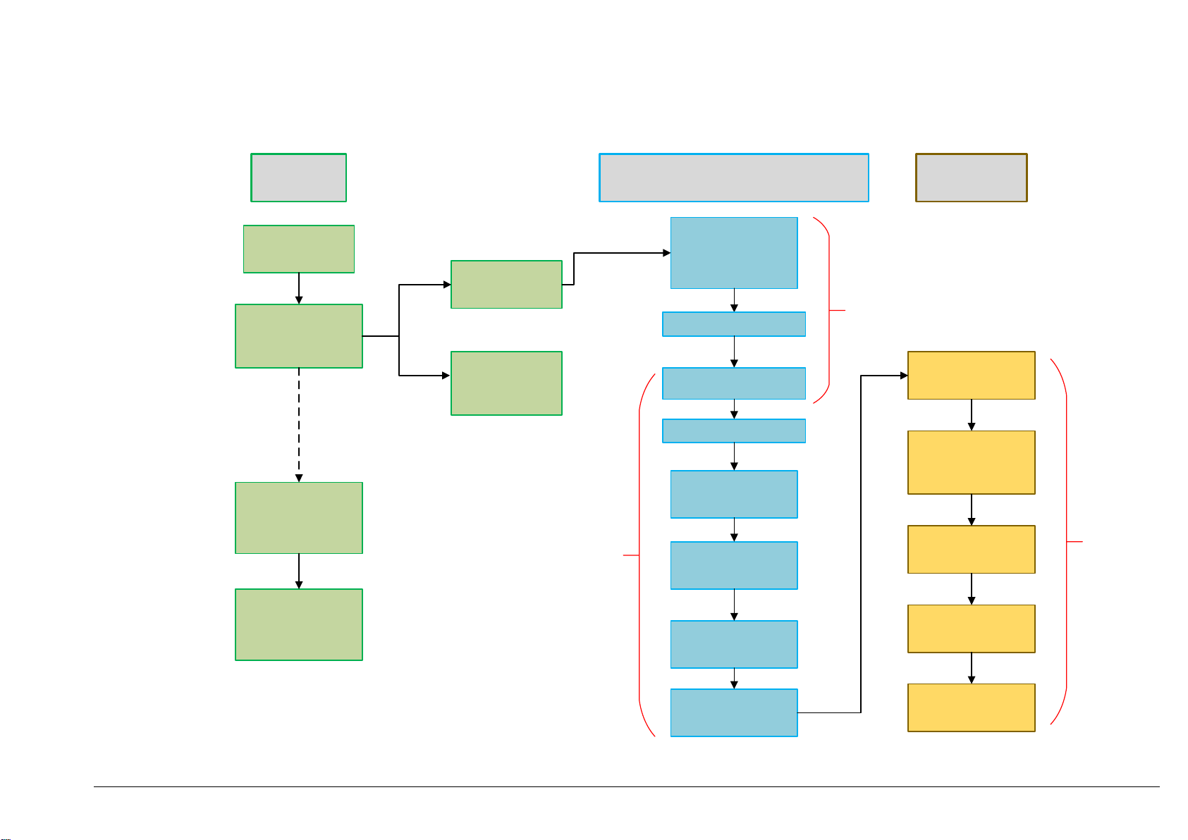
Below is the Telecell Work Flow Diagram showing the following processes:
Ordering
Installation
Test and Commission
Telecell Installation Manual Introduction
TL-006175-PR Issue 5 © Telensa Ltd 2018 Page 5
Page 6
Telecell Installation Manual
Introduction
TL-006175
-PR
Issue 5 © Telensa Ltd 2018
Page
6
Pre-Ship
Activity
Telecells ordered
Telecells shipped and
entered onto TGC by
Telensa
Telensa export the
Telecell information
into the PLANet
system
storage
pre-install
Placed in
Customer stores
Sent to Luminaire
manufacturer for
Pre-Install
Installation and Setup Process
Brought from
Customer stores for
installation
Capture relevant Data
Perform Power On/Off
Test
Assign Telecell to Asset
Assign Programs
(control/monitor/
alarm)
Set Map Location
Test &
Commissioning
Process
Installer Activity
Check Event Log
Check power
readings show lamp
type is assigned
Poll Asset
User can now view
the Telecells on the
Telecells page within
System Administrator Activity
Set Dimming Module
the PLANet UI
Assign Lamp Type
Some activities may be performed by Telensa or Customer depending on the agreed contract
System Administrator Activity
Override Asset
Type
Poll Asset
Page 7
Telec
ell Installation Manual
Introduction
TL-006175
-PR
Issue 5 © Telensa Ltd 2018
Page
7
1.2 General Warnings and Cautions
This section provides safety and regulatory warnings, cautions and information for the
Telecell and its internal components. Details of manufacturer's source documents are
noted where they are used.
Installers must be suitably trained and qualified for electrical work, according to the laws
and local codes for the locality and country where the unit will be installed. This unit must
only be installed by personnel that have been trained by Telensa or their representatives to
carry out this work.
The supply voltage present in the luminaire and its plug in locking type socket is hazardous
and all necessary precautions must be taken to ensure the safety of the installer. Isolate
the supply to the plug in locking type socket before removing an old photocontrol, and
installing the Telecell.
The transmitter must not be co-located or operated with any other antenna or transmitter.
This equipment should be installed and operated with a minimum distance of 20cm from
bystanders.
1.3 Packing and Handling Instructions
Telecells are electronic devises containing processors, a radio module and memory.
Although encased in a robust outer shield, Telecells should be treated with care.
Dropping the Telecell from a height could cause irreparable damage.
Ensure that pins are protected, remaining in their original packaging and kept dry during
transportation and installation.
If returned to Telensa, Telecells must be packaged to the same standard prior to shipping.
Page 8

Telec
ell Installation Manual
Introduction
TL-006175
-PR
Issue 5 © Telensa Ltd 2018
Page
8
1.4 Telecell Regulatory Statements and Compliance Information
1.4.1 United States of America (FCC)
This device complies with Part 15 of the FCC Rules. Operation is subject to the following
two conditions: (1) this device may not cause harmful interference, and (2) this device
must accept any interference received, including interference that may cause undesired
operation.
This equipment has been tested and found to comply with the limits for a class B digital
device, pursuant to Part 15 of FCC rules. These limits are designed to provide reasonable
protection against harmful interference in a residential environment. This equipment
generates, uses and can radiate radio frequency energy and, if not installed and used in
accordance with the instructions, may cause harmful interference to radio communications.
However, there is no guarantee that interference will not occur in a particular installation If
this equipment does cause harmful interference to radio or television reception, which can
be determined by turning the equipment off and on, the user is encouraged to try to correct
the interference by one of the following measures:
Reorient or relocate the receiving antenna
Increase the separation between the equipment and receiver
Consult a dealer or an experienced radio/TV technician for help
Note that no changes shall be made to the equipment without the manufacturer’s
permission as this may void the user’s authority to operate the equipment.
This transmitter must not be co-located or operated with any other antenna or transmitter
This device complies with Part 2.1091 of the FCC Rules for an uncontrolled environment.
This equipment should be installed and operated with a minimum distance of 20cm
between the radiator and your body.
Transmit Band: 902.0 – 928.0 MHz
Transmit Power: 20 dBm
1.4.2 Canada (IC)
This device complies with Industry Canada’s licence-exempt RSSs. Operation is subject to
the following two conditions: 1) This device may not cause interference; and 2) This device
must accept any interference, including interference that may cause undesired operation of
the device.
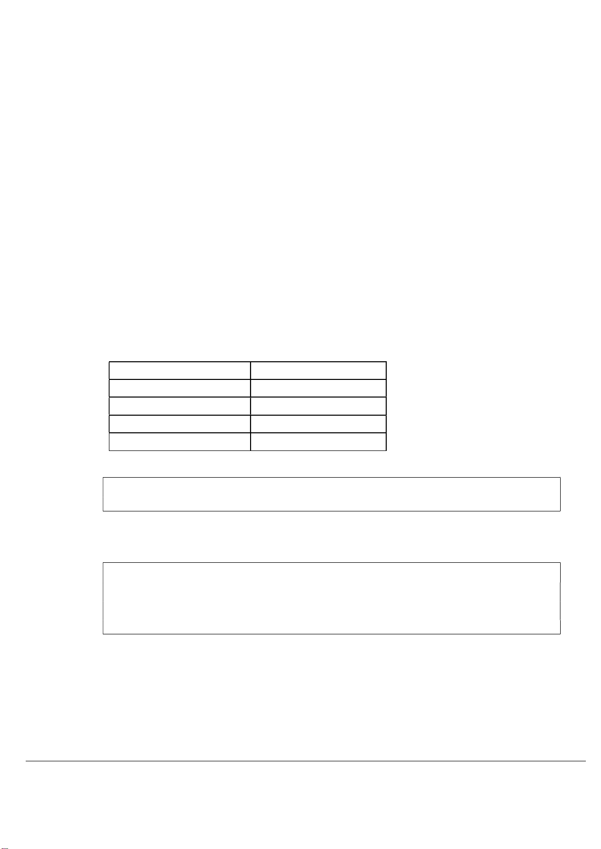
The radio transmitters (12199A-2TXD and 12199A-2NPD) have been approved by
Industry Canada to operate with the antenna types listed below with the maximum
permissible gains indicated. Antenna types not included in this list, having a gain greater
than the maximum gain indicated for that type, are strictly prohibited for use with this
device.
Page 9
Telec
ell Installation Manual
Introduction
TL-006175
-PR
Issue 5 © Telensa Ltd 2018
Page
9
This device is exempt from the standard RSS-102 RF exposure assessment requirements
section 2.5.2. This equipment must be installed and operated with a minimum distance of
20 cm between the radiator and passers-by.
Déclaration de conformité Industrie Canada (IC)
Le présent appareil est conforme aux CNR d’Industrie Canada (IC) applicables aux
appareils radio exempts de licence.
L’exploitation est autorisée aux deux conditions suivantes:
1) l’appareil ne doit pas produire de brouillage;
2) l’appareil doit accepter tout brouillage radioélectrique subi, même si le brouillage est
susceptible d’en compromettre le fonctionnement.
Les émetteurs radio (12199A-2TXD and 12199A-2NPD) ont été approuvés par Industrie
Canada pour fonctionner avec les types d'antenne énumérés ci-dessous avec les gains
maximaux admissibles indiqués. Les types d'antennes non inclus dans cette liste, ayant un
gain supérieur au gain maximal indiqué pour ce type, sont strictement interdits pour une
utilisation avec cet appareil.
Cet appareil est exempté des exigences habituelles d'évaluation de l'exposition RF de
RSS-102, section 2.5.2. Cet équipement doit être installé et utilisé avec une distance
minimale de 20 cm entre le radiateur et les passants.
Telensa Part Number Isotropic Gain (dBi)
ANT-S-EF-M 2
ANT-S-TW-A 2
ANT-S-LP-A 0
ANT-S-HG-A 5
Transmit Band: 902.0 – 928.0 MHz
Transmit Power: 20 dBm
1.4.3 Europe (ETSI)
Essential requirements of Directive 2014/53/EU
Manufacturer: Telensa Limited, Iconix 3, CB22 3EG, UK
Transmit Band: 868.0 to 868.6 MHz
Transmit Power: 14 dBm ERP
Page 10
Telec
ell Installation Manual
Introduction
TL-006175
-PR
Issue 5 © Telensa Ltd 2018
Page
10
1.5 Related Information
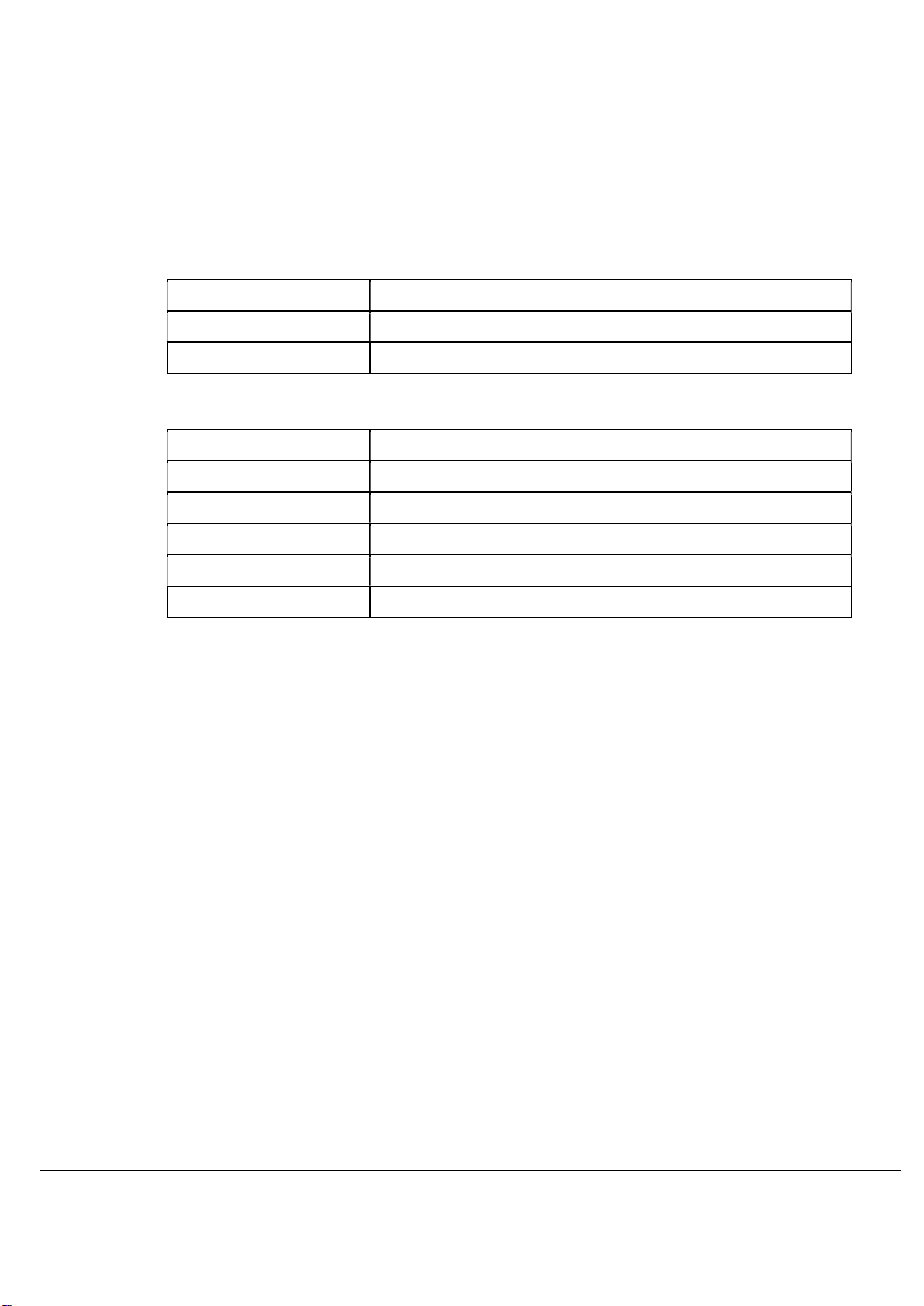
[TL-000762-ST] System Glossary
[TL-005536-PR] System Overview Manual
[TL-005716-PR] PLANet User Guide
1.6 Terminology
PLANet Public Lighting Active Network
GPS Global Positioning System
OOS Orphan Outstation
OSID Outstation Identification Number
OS Outstation
ROS Relay Outstation
1.7 Essential information
1.7.1 Installer
At the point of installation, it is important to match the Asset ID to the OSID. The installer
must confirm the correct operation of the Power On / DIM / Off test cycle as follows:
1) Turn ON the mains supply to the Telecell. The lamp will illuminate for 50
seconds, then turn OFF. If the unit is fitted with a dimming unit it will illuminate
for 50 seconds but after approximately 25 seconds it will DIM to approximately
50%.
Note: When powered up, the unit may switch ON then momentarily switch
OFF, this operation is normal and is the Telecell auto-sensing between
Analogue and DALI.
2) After 50 seconds has elapsed the lamp will turn OFF.The test is now
complete. There is an issue if the lamp fails to operate as described.
Page 11

Telec
ell Installation Manual
Introduction
TL-006175
-PR
Issue 5 © Telensa Ltd 2018
Page
11
The Telecell is now scanning for Basestations and Relays to enable a connection to the
Server.
After 15 minutes the lamp will switch back ON if the Telecell has not connected to the
Server (this can take a few hours), or has not received timing from its GPS (GPS variant
only).
Once the Telecell Connects or receives Timing, it will start operating to a photocell style
programme.
1.7.2 Administrator
A Customer System Administrator will complete the import, asset set up and
commissioning phase.
1.7.3 Pre-Provisioning
Ensure Telecells are loaded onto PLANet.
1.7.4 Power Requirements
ALERT: Report any safety or installation maintenance issues to the installation project manager to
schedule a repair.
1.8 Recording Telecell Identity at Installation
Note: It is essential that specific information is recorded with regards to the column/pole, its lamp
and the fitted Telecell ID (OSID). It is essential to map the correct OSID to the unique
Asset ID. See section 3.6.
Each PLANet Telecell has a unique identity number that is programmed into it at time of
manufacture, which is used by the system to distinguish it from others.
Operators of a PLANet network will want to control and monitor lights by reference to the
column in which the Telecell is fitted rather than by the Telecell identity number.
It is necessary to record and enter which Telecell identity number is fitted into which
column into the system.
It is vital for proper functioning of the system to ensure the matching of Telecell IDs and
column references is done accurately, otherwise the system may only appear to be
working and when, for example, a fault is reported, the mistake discovered as the fault
would not be found in the reported column but in another one. Tracking and correcting this
kind of mistake could be time consuming.
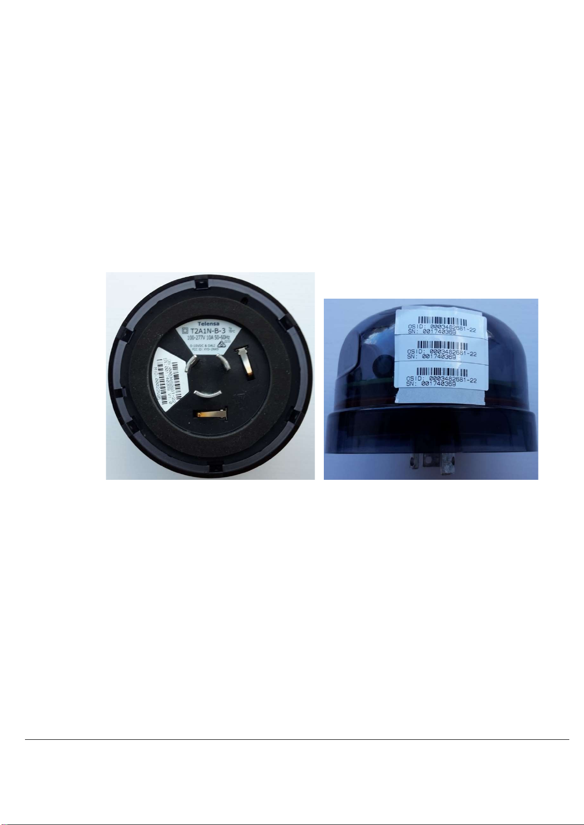
Note: There are two numbers on the label:
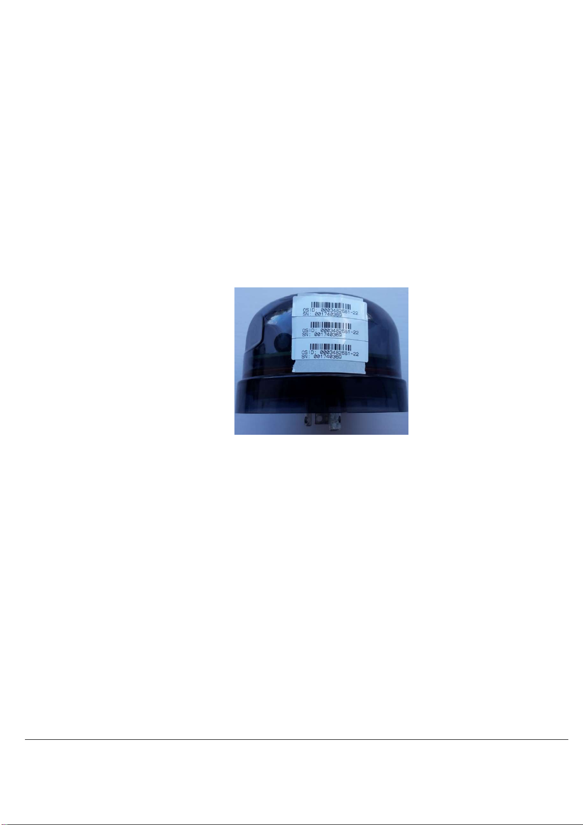
The Telecell ID can be found on a printed label on the base of the Telecell.
the OSID which is the Telecell ID (also barcoded)
Page 12
Telec
ell Installation Manual
Introduction
TL-006175
-PR
Issue 5 © Telensa Ltd 2018
Page
12
o The OSID has the following format 0001234567-xx where xx are check
digits for the actual number
The Telecell serial number
The Telecell is supplied with three identical labels. These are intended for use as follows:
To attach within or outside the luminaire. Inside somewhere clearly visible is
recommended if possible.
Note: avoid locations that will get too hot.
To attach to a suitable tag (located in the base of the column).
To attach to installation documentation (see section 3.6). Typically, this will be a
sheet with asset IDs and a space next to each to attach the label from the
associated Telecell.
It is very important that installation sheets are completed accurately and returned promptly
to the operation centre. This is to ensure that the association between the Telecell and the
column can be added to the system.
Note: The system cannot operate properly without this.
When used with asset management systems that provide this facility, Telecell IDs and the
matching column reference may be captured using PDAs or similar. The Telecell and
Column IDs can then be loaded electronically into the asset management system, and
from there into PLANet.
Note: This removes the need to manually match the Telecell and column IDs on the PLANet
system.
Page 13
Telec
ell Installation Manual
Introduction
TL-006175
-PR
Issue 5 © Telensa Ltd 2018
Page
13
1.9 Standard Deployment Equipment
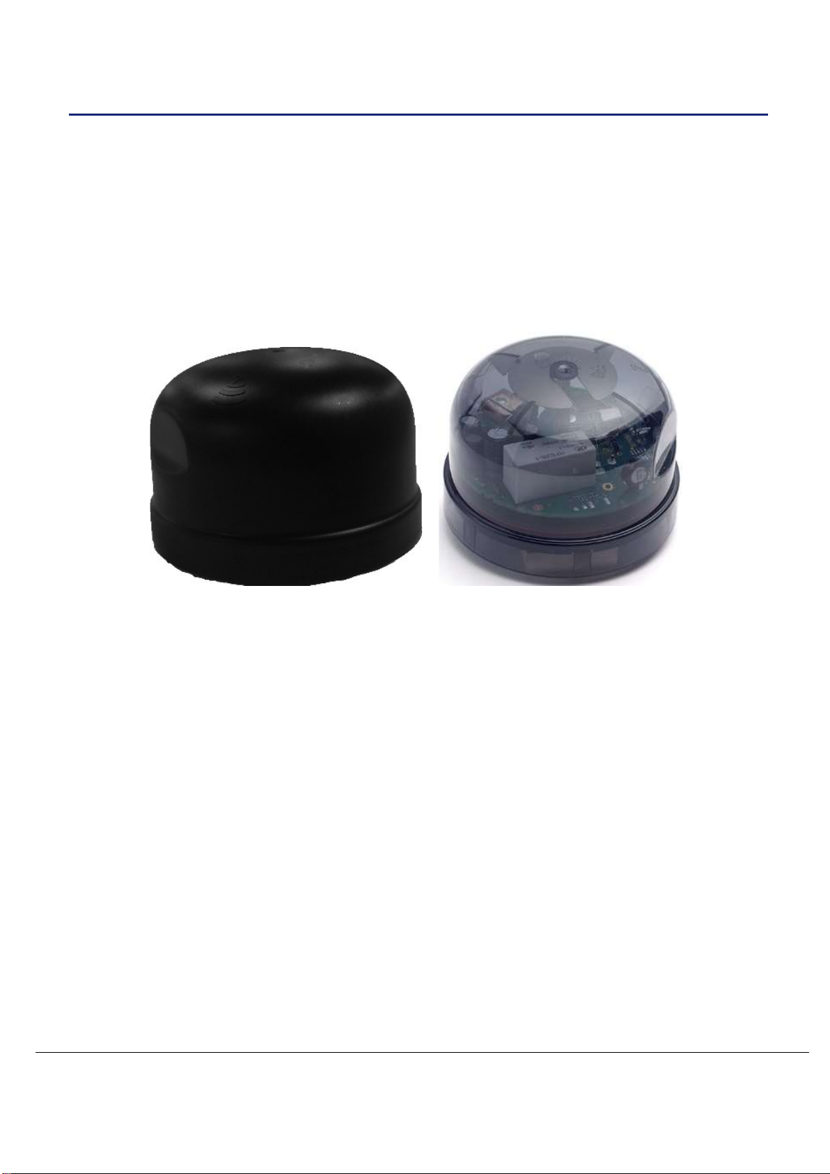
The packing list will vary dependant on the type of Telecell being installed.
Plug in locking type Telecells will fit directly into a plug in locking type socket whereas
Conduit, Two-Part and Post Top Telecells can come pre-installed.
1.9.1 Standard deployment equipment includes:
1 x label affixed to the Telecell unit
1 x label to fix to paper installation record sheet
1 x label to be affixed to column fuse holder
1 x spare
1.9.2 Installer Supply List:
1 x data capture device (if applicable)
1 x paper installation record sheet (optional)
Page 14
Telec
ell Installation Manual
Installation
TL-006175
-PR
Issue 5 © Telensa Ltd 2018
Page
14
2 Installation
Telecells are manufactured in many different forms. Each form is utilised dependent upon
the environment it is to be fitted.
Prior to installation, check the column and report any safety or installation maintenance
issues to the installation project manager so that a repair can be scheduled.
2.1 Installation Tasks
The following are the available Telecell variants and steps for installation:
Plug in locking type (external)
ALERT: Ensure to fit the plug in locking type socket correctly following supplier guidelines
1) Align the plug in locking type pins with the socket and insert. The Neutral pin on a
Telecell is wider and will only fit the hole next to the ‘N’ marker on the socket, twist
and lock.
2) To lock the Telecell in place, push down and twist clockwise. Pull the Telecell up
to confirm it is installed correctly. For wiring information see section 2.2.
3) Turn on the mains supply to the Telecell and observe the Power On / DIM / Off
test cycle as described in section 1.7.1. It will turn on for 50 seconds, then turn off.
If dimmable: on 25 seconds, dim 25 seconds, then turns off.
4) Record the necessary data as detailed under section 1.7. Data capture will be
dependent on available tools, for example: paper based or import via PDA.
5) Affix the Telecell labels described in section 1.7 as necessary.
Page 15
Telec
ell Installation Manual
Installation
TL-006175
-PR
Issue 5 © Telensa Ltd 2018
Page
15
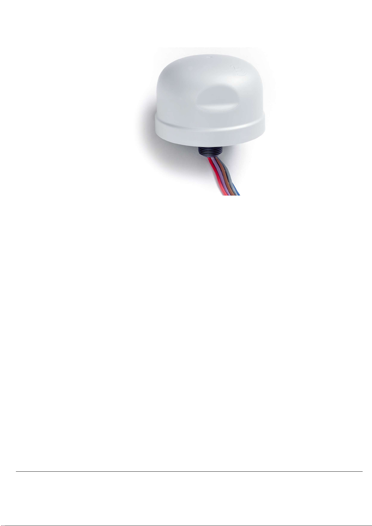
Conduit (external)
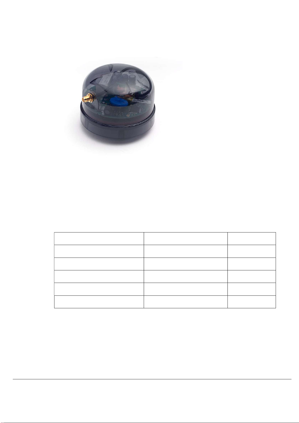
The conduit Telecell is affixed to the lamp via a 20mm diameter thread. The nut securing
the Telecell should be tightened to 3 Nm.
ALERT: Check the rubber sealing washer is intact and undamaged to prevent water getting in.
Telecells with built in dimming have 5 wires and those without have 3 wires.
The Telecell must be wired as per section 2.2.
1) Turn on the mains supply to the Telecell and observe the Power On / DIM / Off
test cycle as described in section 1.7.1. It will turn on for 50 seconds, then turn off.
If dimmable: on 25 seconds, dim 25 seconds, then turns off.
2) Record the necessary data as detailed under section 1.7. Data capture will be
dependent on available tools, for example: paper based or import via PDA.
3) Affix the Telecell labels described in section 1.7 as necessary.
Page 16
Telec
ell Installation Manual
Installation
TL-006175
-PR
Issue 5 © Telensa Ltd 2018
Page
16
Two-Part (internal, requires antenna)
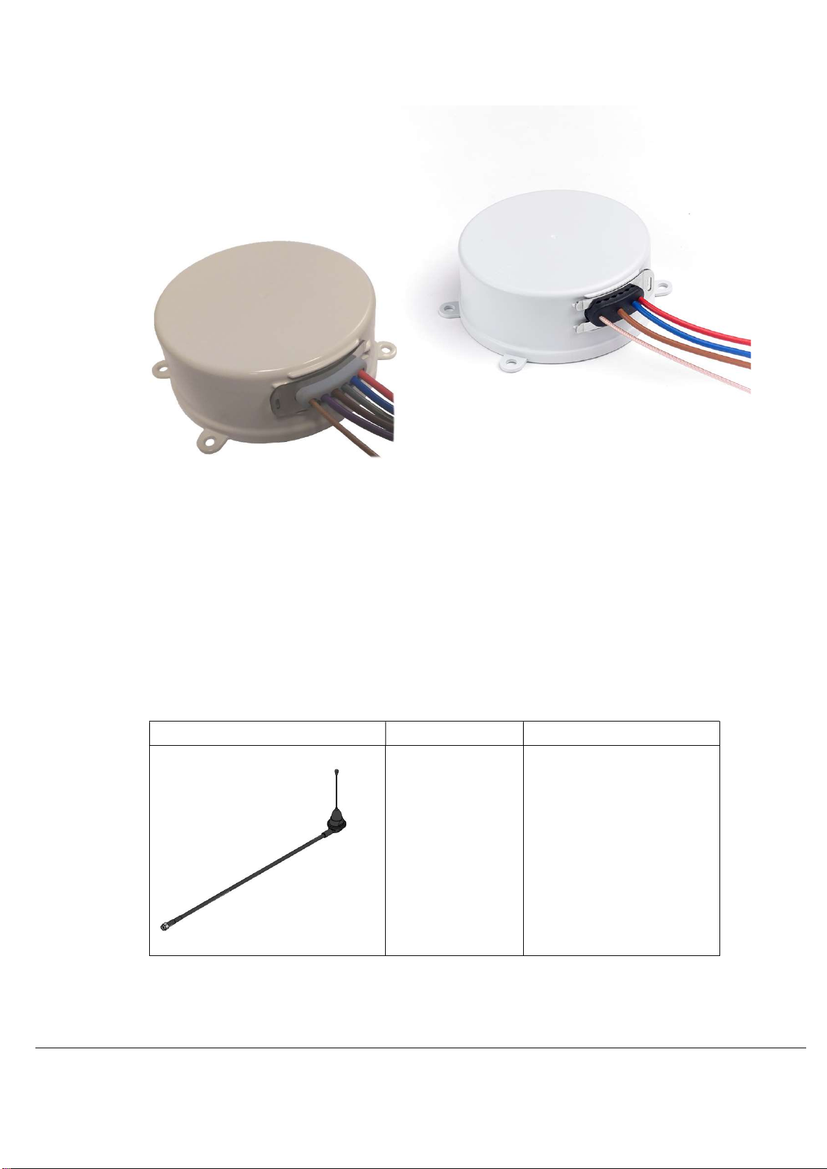
The Two-Part Telecell connections (mains, dimming and antenna) are provided by a wiring
loom, which must be connected inside the luminaire.
The Two-Part Telecell is designed for applications without a plug in locking type socket, or
20mm access hole. This Telecell requires an external antenna to be fitted. Typical
examples would be:
Heritage lamps that must conform to strict external appearance
Traffic bollard or illuminated road sign
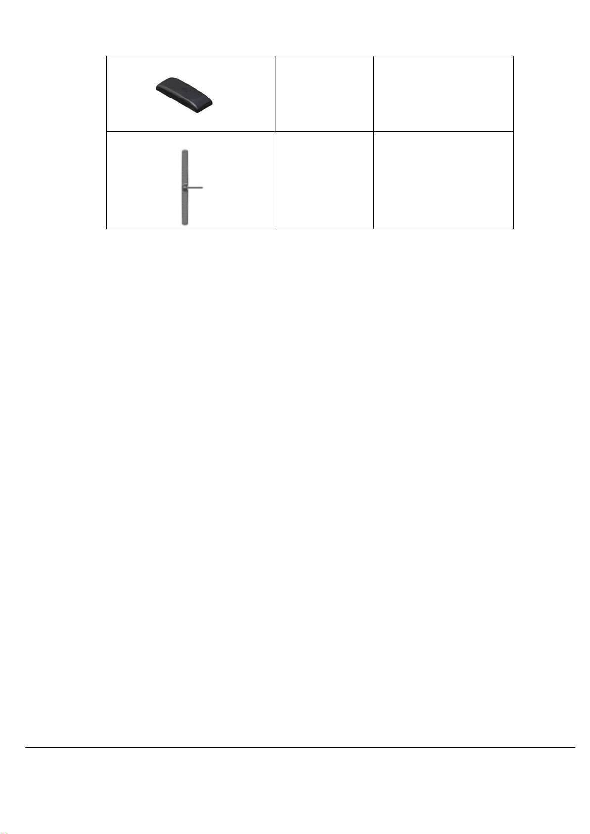
Two-Part Telecells consist of a Telecell and an external antenna. The three external
antennas available are:
Antenna Type Part Number Description
MONOPOLE
ANT-S-TW-A
ANT-S-TW-E
915MHz monopole (SMA)
868MHz monopole (SMA)
Page 17
Telec
ell Installation Manual
Installation
TL-006175
-PR
Issue 5 © Telensa Ltd 2018
Page
17
LOW PROFILE
ANT-S-LP-A
ANT-S-LP-E
915MHz low profile (SMA)
868MHz low profile (SMA)
EASY FIT
ANT-S-EF-M 868MHz and 915MHz
easy fit (SMA)
1) These Telecells are fitted inside the fixture securely, without compromising the
other components and positioned in a manner in keeping with the natural
workings.
Note: This must be wired to the incoming supply and outgoing ballast/driver
along with the dimming wires as in section 2.2.2.
2) Connect the antenna to the Telecell.
Note: DO NOT OVER TIGHTEN RF CONNECTOR (0.3 – 0.6Nm).
3) Turn on the mains supply to the Telecell and observe the Power On / DIM / Off
test cycle as described in section 1.7.1. It will turn on for 50 seconds, then turn off.
If dimmable: on 25 seconds, dim 25 seconds, then turns off.
4) Record the necessary data as detailed under section 1.7. Data capture will be
dependent on available tools, for example: paper based or import via PDA.
5) Affix the Telecell labels described in section 1.7 as necessary.
2.1.1 Two-Part Mounting
The maximum screw insertion depth is 12mm. Base mounting lugs are snap off, if
required, to enable mounting in confined spaces.
2.1.2 Two-Part Antenna Connection
The Two-Part version antenna connection uses an SMA connector, the plug is fitted to the
Telecell. Additional antenna cabling must use 50ohm coax with low loss at the operating
frequency (868 MHz for ETSI variants, 915MHz for FCC variants). It is recommended to
contact Telensa before using a longer antenna cable.
Page 18
Telec
ell Installation Manual
Installation
TL-006175
-PR
Issue 5 © Telensa Ltd 2018
Page
18
Post Top (internal, requires antenna)
The Post Top Telecell is fitted as per the plug in locking type but has an external antenna
same as the Two-Part Telecell. This Telecell is typically used where the plug in locking
type socket has been installed inside the luminaire casing.
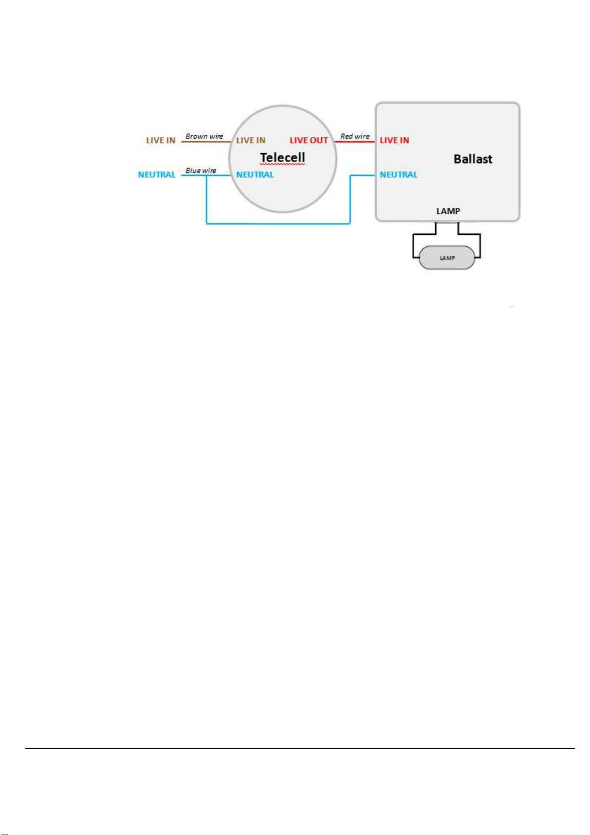
2.2 Wiring Diagrams
For Telecells with attached wires, the wiring colours depend on the market the Telecell is
intended for, as shown here:
Live In
Neutral
Switched Live Out
dimming control positive
dimming control negative
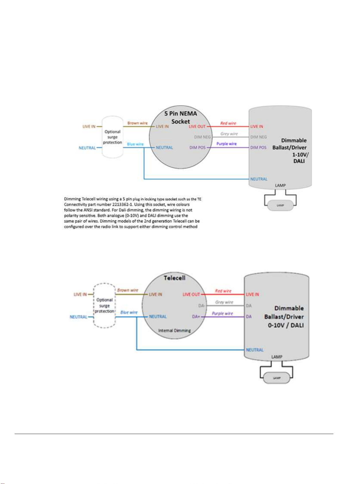
The following diagrams show how the Telecells should be wired. These diagrams show
the ETSI wiring colours. For a FCC installation, substitute the colours using the table
above:
ETSI FCC
Brown Black
Blue White
Red Red
Purple Violet
Grey Grey
Page 19
Telec
ell Installation Manual
Installation
TL-006175
-PR
Issue 5 © Telensa Ltd 2018
Page
19
2.2.1 Wire Gauge
The FCC cable is 18AWG. The ETSI cable is 20AWG.
All wires from ETSI Telecells are 20AWG, 105C rated PVC insulation. For the FCC
variants, the Live In, Live Out and Neutral wires are 18AWG and the dimming control wires
are 20AWG. Standard length is 1m.
2.2.2 Plug in locking type
2.2.3 Conduit and Two-Part with Dimming
Page 20
Telec
ell Installation Manual
Installation
TL-006175
-PR
Issue 5 © Telensa Ltd 2018
Page
20
2.2.4 Conduit and Two-Part without Dimming
Page 21

Telec
ell Installation Manual
Commissioning
TL-006175
-PR
Issue 5 © Telensa Ltd 2018
Page
21
3 Commissioning
3.1 Commission a Telecell
The System Administrator should complete this commissioning phase.
When installing, the only available confidence check for an installer is the Power On / DIM
/ Off test.
To functionally check each unit fully, the Telecell must be connected to the system,
assigned an Asset ID and the correct lamp type and Control, Monitoring and Alarm
programs set.
Telecells are loaded onto each system when dispatched. To confirm the Telecell OSID is
loaded, filter on the Telecells page within the UI.
3.2 Set Up a Telecell
The Telecell(s) must be connected prior to the commissioning phase. In areas with poor
coverage, it may be necessary to set up Relays (ROS – Relay Outstation).
3.3 Configuration
Once the asset has been imported, use the following steps to ensure the Asset returns
data and operates as expected.
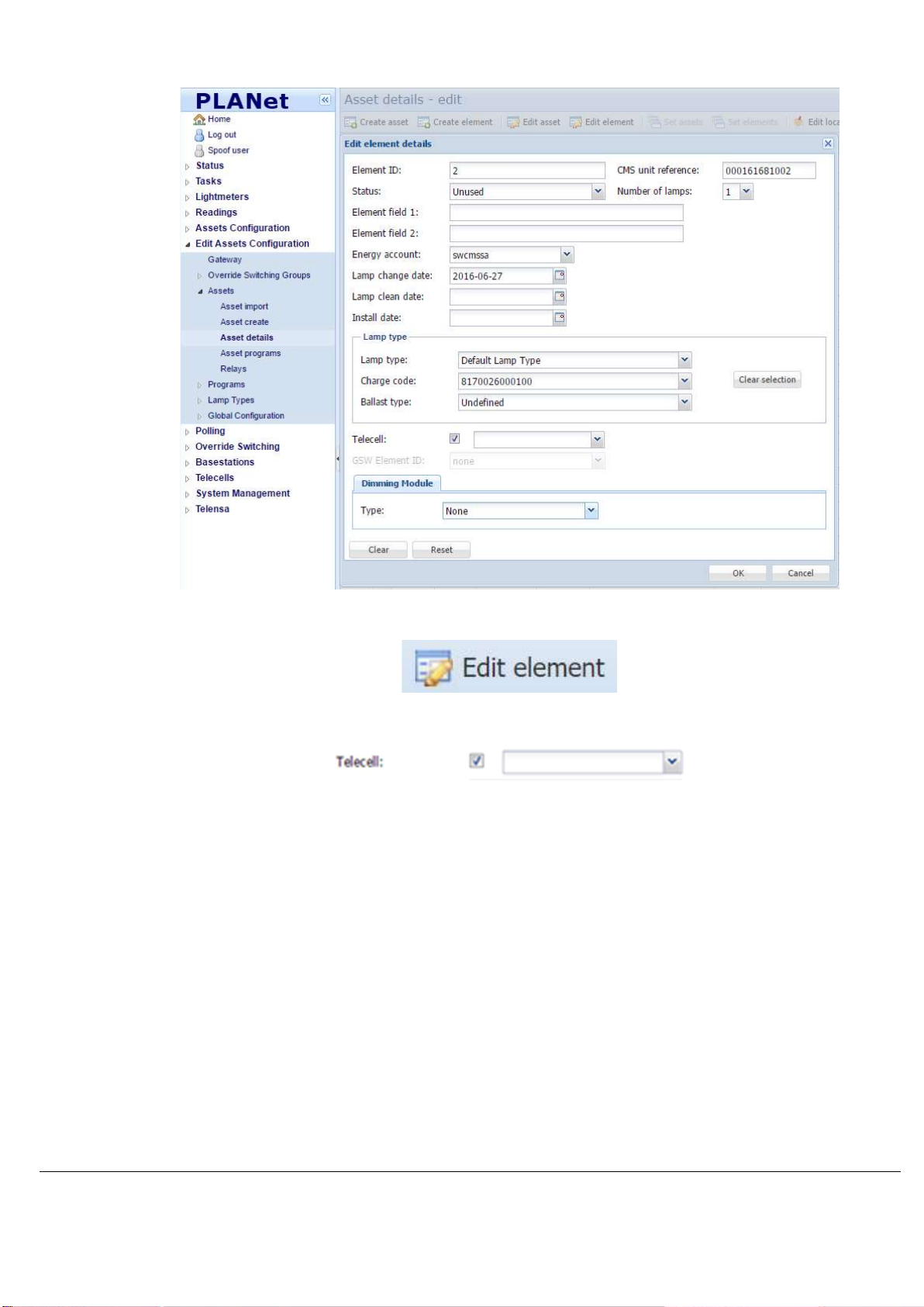
3.3.1 Set Telecell to Asset
1) Go to Edit Assets Configuration > Gateway > Assets > Asset Details:
Page 22
Telec
ell Installation Manual
Com
missioning
TL-006175
-PR
Issue 5 © Telensa Ltd 2018
Page
22
2) Select the Asset and click Edit Element:
3) At the Telecell section, tick the checkbox and add the Telecell OSID to enable it:
4) Ensure the Status is set to Active.
5) To set Dimming, click the drop-down button in the Dimming Module section.
6) To set the Lamp Type, click the drop-down button in the Lamp Type section.
7) Click OK.
Page 23
Telec
ell Installation Manual
Commissioning
TL-006175
-PR
Issue 5 © Telensa Ltd 2018
Page
23
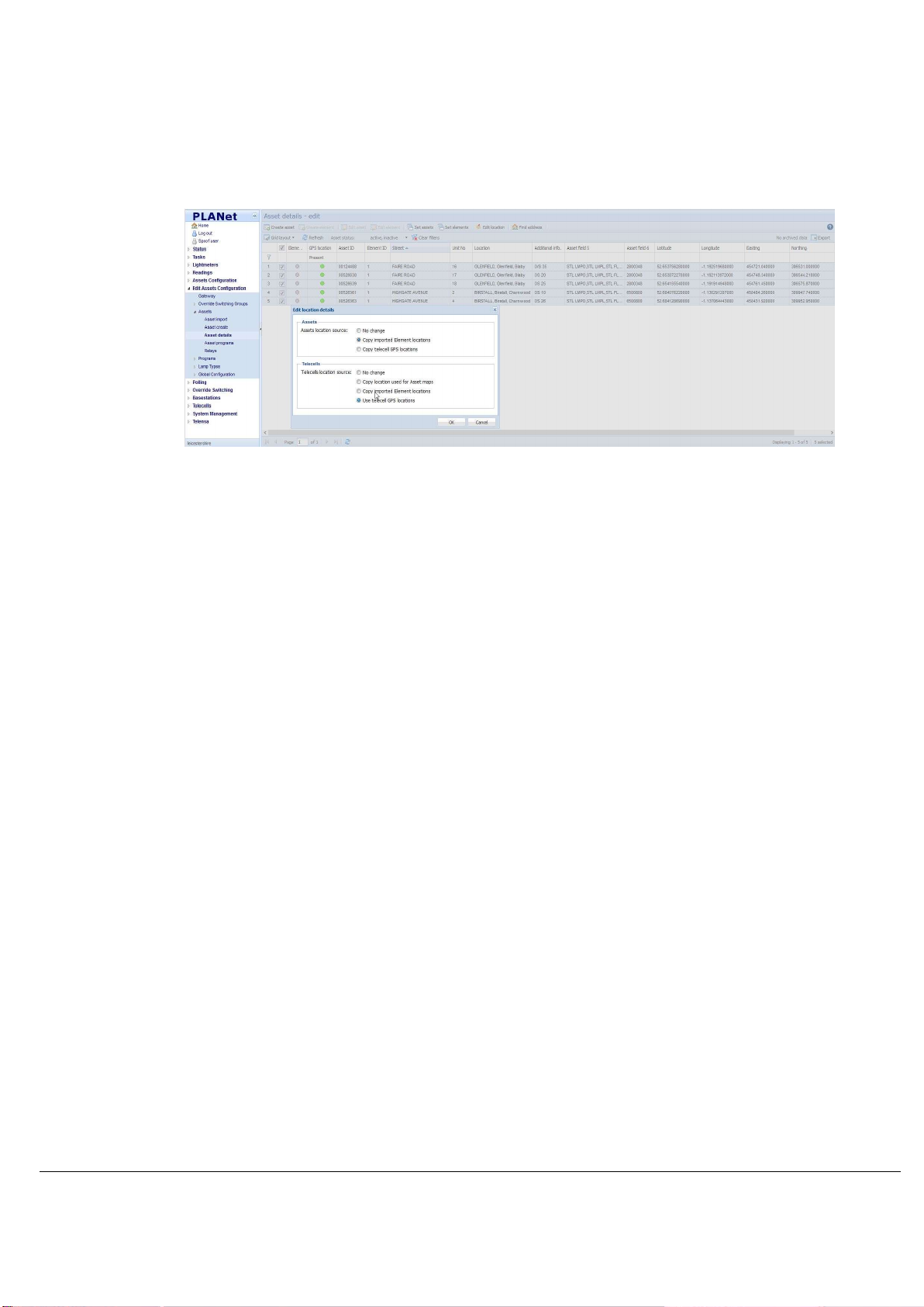
3.3.2 Set Location
Once the assets are imported it is necessary to set the location sources for both the
Telecell and Asset.
1) Go to Edit Assets Configuration > Gateway > Assets > Asset Details:
2) Select the Assets.
3) Click Edit Locations.
4) Select Copy imported Element locations (Assets location source).
5) Select Use Telecell GPS locations (Telecells location source).
6) Click OK.
Latitude and Longitude contained within the Asset details page and the Telecell page is
derived from the data uploaded to PLANet from the Mayrise hand held devices.
Whereas,
GPS Latitude and GPS Longitude displayed on the Telecell page is generated by the
Telecell during authentication when connecting to the Basestation.
Note: The Assets location source alternative: No change, is used if the location data to be
used is predefined and already loaded into PLANet.
Note: The Telecell location source alternative: Copy imported Element locations is used in
combination with a specific mobile deployment tool, which provides the GPS location
during deployment.
Note: Copy Telecell GPS locations would only be selected if no location data is imported from
a CMS system to the PLANet system.
Page 24
Telec
ell Installation Manual
Commissioning
TL-006175
-PR
Issue 5 © Telensa Ltd 2018
Page
24
Note: The Telecells location source alternative: No change, would be selected if no location
data is imported from a CMS system to the PLANet system, or for Copy location used for
Asset maps if the Telecell variant does not provide GPS.
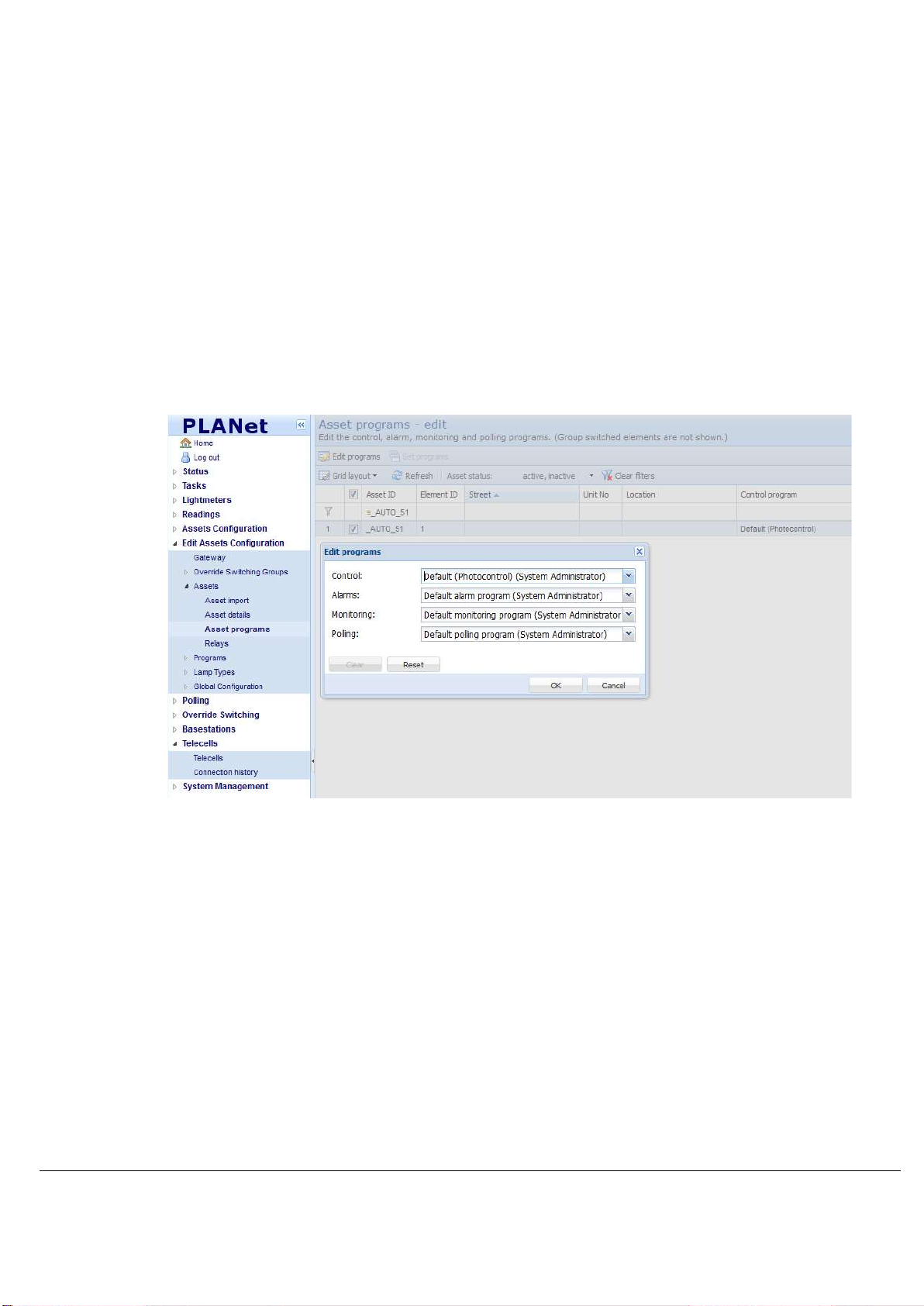
3.3.3 Set Programmes
Once the assets are imported, assign programmes if required:
Control
Monitoring
Alarm
Polling
1) Go to Gateway > Assets > Asset Programs:
2) Select the Assets to assign programs using the checkboxes.
3) Click Edit Programs to edit a single asset or Set Programs to set multiple
assets.
4) Select the relevant programs by using the drop-down lists: Control, Alarms,
Monitoring.
5) Once complete, return to the Gateway and click Save and Reprogram.
Page 25
Telec
ell Installation Manual
Commissioning
TL-006175
-PR
Issue 5 © Telensa Ltd 2018
Page
25
3.4 Operational Checks
For a Telecell to be controlled and return meaningful data it must be set up correctly.
Ensure each Telecell is:
Connected
Assigned to an Asset
Has a Control Program with appropriate dimming levels set within the Power tab
Has the correct Lamp Type and Charge Code Assigned (make a note of the
Circuit Watts within the Charge Code)
3.5 Bring the Telecell into Service
3.5.1 Connection Status
Once installed and powered, the Telecell should connect to the Central System within a
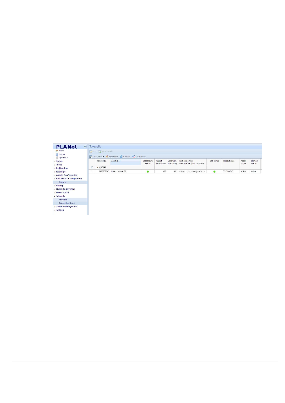
few hours. This can be confirmed by observing the Telecells Page within the User
Interface.
Filter the Telecell ID column for the OSID.
Note: When a Telecell connects, the Last Known Status column symbol turns green and data
becomes present in the Last Connection Confirmation [data received] column. If the
Telecell is not connected, the Test and Commissioning phase cannot be completed.
Note: The Last Known Status column is the result of either the success or failure of any last
communication with the Telecell.
Page 26
Telec
ell Installation Manual
Commissioning
TL-006175
-PR
Issue 5 © Telensa Ltd 2018
Page
26
3.5.2 Telecell Control
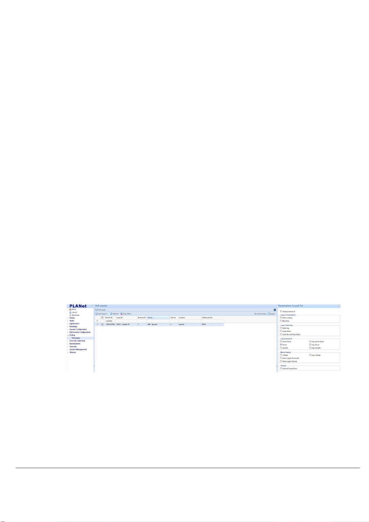
To test if a Telecell can be controlled and return meaningful data, use the Polling and
Override functions within the PLANet user interface. The sequence is as follows:
1) Poll the Asset (for the power parameter) and record the reading, found within the
Readings page – Readings > Lamp Electrical > Power.
2) Override the Asset to Full On.
3) Poll the Asset (for the power parameter) and record the reading, found within the
Readings page.
4) Include if the dimming unit is installed - Override the Asset to DIM2.
5) Include if the dimming unit is installed - Poll the Asset (for the power parameter)
and record the reading, found within the Readings page.
6) Override the Asset to Return to Normal Operation.
7) Poll the Asset (for the power parameter) and record the reading, found within the
Readings page. Confirm that the readings obtained are as expected in
accordance with the associated Lamp Type.
Note: The Properties section can also be used to carry out this task on single
Assets if the User is familiar with this process.
3.5.2.1 Polling
1) To Poll an Asset, navigate to the Polling page, select the Asset and Parameter
to be polled and click the Poll Asset tab.
The progress of this task can be viewed within the Tasks > Polling page.
Page 27
Telec
ell Installation Manual
Commissioning
TL-006175
-PR
Issue 5 © Telensa Ltd 2018
Page
27
3.5.2.2 Override
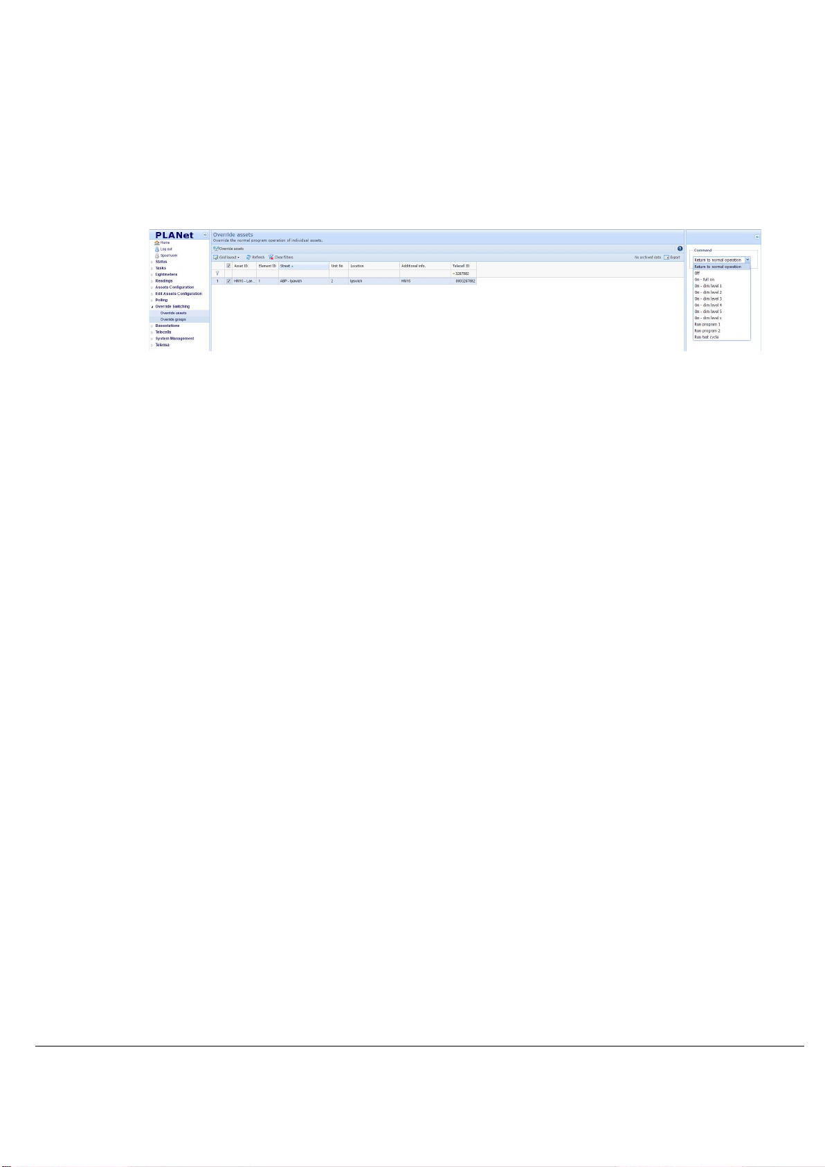
2) To Override an Asset, navigate to the Override page, select the Asset and
Parameter to be Overridden and click the Override Asset tab.
The progress of this task can be viewed within the Tasks > Override Switching
page.
Monitor the Event Log 24-48 hours after setup to ensure Telecells are operating
as expected.
Page 28
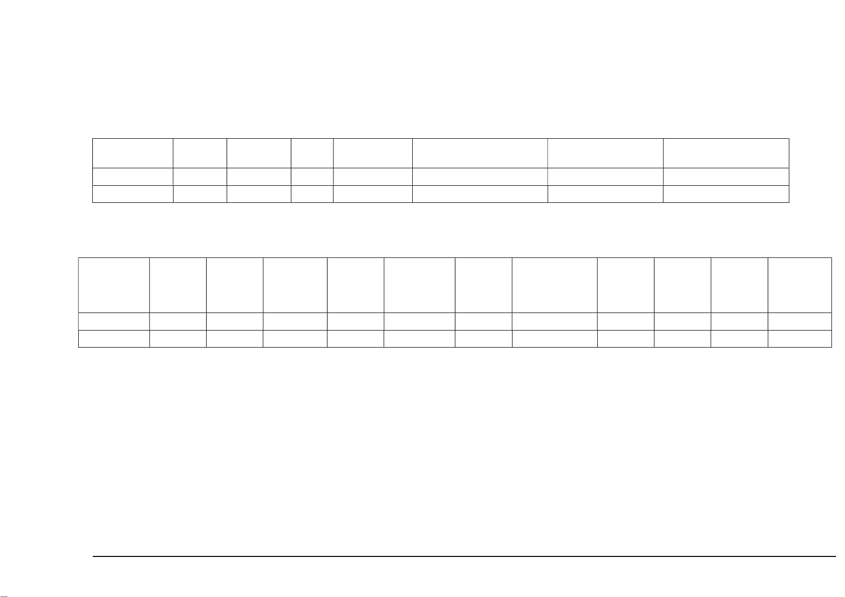
3.6 Example Installation Data Capture Sheet
Asset ID Latitude Longitude Street Lamp Type Additional Information Confirm Power
Attach Telecell Label
ON/DIM/OFF Test
3.7 Example Commissioning Record Sheet
Telecell ID
(OSID)
Asset ID Unit
Number
Lamp
Type
(Nominal
Watt)
Control
Program
Monitoring
Program
Alarm
Program
Power
[ON/DIM/OFF]
Test Cycle
Override
ON
[Power]
DIM1
[Power]
DIM2
[Power]
Pass/Fail
Telecell Installation Manual Commissioning
TL-006175-PR Issue 5 © Telensa Ltd 2018 Page 1
 Loading...