

Telenetics Corporation FT100 S Installation And Operation Manual

FT100 S
Installation and Operation Manual
Telenetics Corporation
25111 Arctic Ocean
Lake Forest, California 92630
Doc No. TEL–6496504603014
February 2001
© 2001 Telenetics

COPYRIGHT
Copyright 2001 Telenetics Corporation
Published by Telenetics, who reserves the right to make improvements in the products
described in this manual as well as to revise this publication at any time and without notice to
any person of such revision or change.
All rights reserved. No part of this publication may be reproduced, transcribed, stored in an
electronic retrieval system, translated into any language or computer language, or be transmitted in any form whatsoever without the prior written consent of the publisher. For additional information contact
Telenetics Corporation
25111 Arctic Ocean
Lake Forest, California 92630
TRADEMARKS
Telenetics is a registered trademark of Telenetics Corporation.
The following are trademarks or registered trademarks of their respective companies or
organizations.
Product Company/Organization
Motorola Data Shelf Motorola
LocalView Motorola
IBM International Business Machines Corporation
AT&T American Telegraph & Telephone
NOTICE
All titles, versions, trademarks, claims of compatibility, etc., of hardware and software products mentioned herein are the sole property and responsibility of the respective vendors. Telenetics makes no endorsement of any particular product for any purpose, nor claims
responsibility for its operation and accuracy.
UPDATES
Updates to the products and the manual are obtainable at participating Telenetics dealers and
distributors, or directly from Telenetics.
ii

FCC REQUIREMENTS
This equipment complies with Part 68 of FCC Rules. Please note the following:
When you order service, the telephone company needs to know:
A. The Facility Interface Code:
04DU9-BN (1.544 Mbps superframe format (SF) without line power)
04DU9-DN (1.544 Mbps SF and B8ZS without line power)
04DU9-1KN (1.544 Mbps ANSI ESF without line power)
04DU9-1SN (1.544 Mbps ANSI ESF and B8ZS without line power)
B. The Service Order Code: 6.0N
A signal power affidavit will be required to guarantee encoded analog content and
billing protection unless this unit is used in combination with an XD type device or
no encoded analog signals and billing information are transmitted. A SAMPLE
AFFIDAVIT is attached. For most uses, the second box is appropriate.
C. The USOC Jack Required: RJ48C
In addition, if requested, please inform the telephone company of the make, model
number and FCC registration number, which are on the label.
The telephone company may change technical operations or procedures affecting your equipment. You will be notified of changes in advance to give you ample time to maintain uninterrupted telephone service.
If you experience trouble with this telephone equipment, please contact
Telenet ic s
25111 Arctic Ocean
Lake Forest, California 92630
for information on obtaining service or repairs. The telephone company may ask that you
disconnect this equipment from the network until the problem has been resolved. If your
equipment continues to disrupt the network the telephone company may temporarily disconnect service. If this occurs you will be informed of your right to file a complaint with the
FCC.
WA R NI N G
This equipment uses, generates, and can radiate radio frequency energy interfering with radio communications if not installed and used in accordance with the
instruction manual. It has been tested and complies with the limits for a Class A
computing device according to FCC Rules, Part 15. Operation of this equipment
in a residential area may cause interference. If it does, you must correct the cause
of the interference. Shielded cables may be necessary with this unit to ensure
compliance with the Class A limits.
Changes or modifications to this unit not expressly approved by the party responsible for compliance could void the user's authority to operate the equipment.
iii

SPECIAL REQUIREMENTS FOR CANADA
Certain requirements exist for data communication products manufactured for use in Canada.
Principle among these requirements is the application of the IC label as described below.
However, certain data communication products do not require the IC label nor adherence to
IC requirements. If this is the case the IC label will not be affixed to the units.
INDUSTRY CANADA (IC) REQUIREMENTS
IC labels are affixed to each unit sold in Canada. This label has the certification number for
that particular unit. The numbers are different for each model.
The Industry Canada label identifies certified equipment. This certification means that the
equipment meets certain telecommunications network protective, operational, and safety
requirements. IC does not guarantee the equipment will operate to the user's satisfaction.
Before installing this equipment, users should ensure that it is permissible to be connected to
the facilities of the local telecommunications company. The equipment must also be installed
using an acceptable method of connection. In some cases, the company's inside wiring associated with a single line individual service may be extended by means of a certified connector
assembly (telephone extension cord). The customer should be aware that compliance with
the above conditions may not prevent degradation of service in some situations.
Repairs to certified equipment should be made by an authorized Canadian maintenance
facility designated by the supplier. Any repairs or alterations made by the user to this equipment, or equipment malfunctions, may give the telecommunications company cause to
request the user to disconnect the equipment. For their own protection users should ensure
that the electrical ground connections of the power utility, telephone lines and internal
metallic water pipe system, if present, are connected together. This precaution may be particularly important in rural areas.
CAUTION
Users should not attempt to make installation connections themselves, but should
contact the appropriate electric inspection authority or electrician.
CANADIAN EMISSION REQUIREMENTS
This Class A digital apparatus meets all requirements of the Canadian Interference-Causing
Equipment Regulations.
Cet appareil numérique de la classe A respecte toutes les exigences du Règlement sur le
matériel brouilleur du Canada.
iv

Table of Contents
Chapter 1, Introduction
GENERAL . . . . . . . . . . . . . . . . . . . . . . . . . . . . . . . . . . 1-1
FUNCTIONAL DESCRIPTION . . . . . . . . . . . . . . . . . 1-1
PHYSICAL DESCRIPTION . . . . . . . . . . . . . . . . . . . . 1-2
Front Panel . . . . . . . . . . . . . . . . . . . . . . . . . . . . . . . . . . 1-2
Rear Panel . . . . . . . . . . . . . . . . . . . . . . . . . . . . . . . . . . . 1-3
FEATURES . . . . . . . . . . . . . . . . . . . . . . . . . . . . . . . . . 1-4
Chapter 2, Installation
General . . . . . . . . . . . . . . . . . . . . . . . . . . . . . . . . . . . . . 2-1
RECEIPT INSPECTION . . . . . . . . . . . . . . . . . . . . . . . 2-1
SITE PREPARATION . . . . . . . . . . . . . . . . . . . . . . . . . 2-2
CONNECTIONS . . . . . . . . . . . . . . . . . . . . . . . . . . . . . 2-3
FT 100S to Network . . . . . . . . . . . . . . . . . . . . . . . . . . . 2-3
FT 100S to Remote Control Device . . . . . . . . . . . . . . . 2-4
FT 100S to DTE . . . . . . . . . . . . . . . . . . . . . . . . . . . . . . 2-5
V.35 Adapter Installation . . . . . . . . . . . . . . . . . . . . . . . 2-5
POWER . . . . . . . . . . . . . . . . . . . . . . . . . . . . . . . . . . . . . 2-7
Chapter 3, Hardware Configuration
GENERAL . . . . . . . . . . . . . . . . . . . . . . . . . . . . . . . . . . 3-1
COVER REMOVAL . . . . . . . . . . . . . . . . . . . . . . . . . . 3-1
CHANGING OPTION SETTINGS . . . . . . . . . . . . . . . 3-2
Grounding . . . . . . . . . . . . . . . . . . . . . . . . . . . . . . . . . . . 3-4
DTE INTERFACE OPTIONS . . . . . . . . . . . . . . . . . . . 3-4
Installing an Interface Card . . . . . . . . . . . . . . . . . . . . . . 3-4
Using a Conversion Adapter . . . . . . . . . . . . . . . . . . . . . 3-5

Chapter 4, Front Panel Option Selection
GENERAL . . . . . . . . . . . . . . . . . . . . . . . . . . . . . . . . . . 4-1
LCD MENUS . . . . . . . . . . . . . . . . . . . . . . . . . . . . . . . . 4-1
Using the Pushbuttons to Select Options . . . . . . . . . . . 4-1
Powerup Displays . . . . . . . . . . . . . . . . . . . . . . . . . . . . . 4-4
PORT STATUS DISPLAY MAIN MENU 1 . . . . . . . 4-5
Line Status . . . . . . . . . . . . . . . . . . . . . . . . . . . . . . . . . . 4-6
DTE Status . . . . . . . . . . . . . . . . . . . . . . . . . . . . . . . . . . 4-7
DIAGNOSTIC OPTIONS MAIN MENU 2 4-8
T1 TESTS . . . . . . . . . . . . . . . . . . . . . . . . . . . . . . . . . . . 4-9
T1 Local Loopback . . . . . . . . . . . . . . . . . . . . . . . . . . . . 4-9
T1 Network Loopback . . . . . . . . . . . . . . . . . . . . . . . . . 4-11
Remote CSU Loopback . . . . . . . . . . . . . . . . . . . . . . . . 4-11
Test In Progress . . . . . . . . . . . . . . . . . . . . . . . . . . . . . . . 4-14
DTE PORT TESTS . . . . . . . . . . . . . . . . . . . . . . . . . . . . 4-14
DTE Port Local Terminal Loopback . . . . . . . . . . . . . . 4-15
DTE Port Remote Terminal Loopback . . . . . . . . . . . . . 4-15
DTE Port Remote Loopback . . . . . . . . . . . . . . . . . . . . . 4-18
With Test Pattern? . . . . . . . . . . . . . . . . . . . . . . . . . . . . . 4-20
DTE Port Test Pattern . . . . . . . . . . . . . . . . . . . . . . . . . . 4-22
Test In Progress . . . . . . . . . . . . . . . . . . . . . . . . . . . . . . . 4-22
Bit Errors Display . . . . . . . . . . . . . . . . . . . . . . . . . . . . . 4-24
Average Bit Error Rate Display . . . . . . . . . . . . . . . . . . 4-24
Elapsed Seconds Display . . . . . . . . . . . . . . . . . . . . . . . 4-24
Restart Test Display . . . . . . . . . . . . . . . . . . . . . . . . . . . 4-25
SELF TEST . . . . . . . . . . . . . . . . . . . . . . . . . . . . . . . . . . 4-25
DS0 MONITOR . . . . . . . . . . . . . . . . . . . . . . . . . . . . . . 4-26
PERFORMANCE HISTORY . . . . . . . . . . . . . . . . . . . . 4-27
% Error Free Seconds . . . . . . . . . . . . . . . . . . . . . . . . . . 4-28
Error Events . . . . . . . . . . . . . . . . . . . . . . . . . . . . . . . . . 4-28
Timed Error Data . . . . . . . . . . . . . . . . . . . . . . . . . . . . . 4-29
CONFIGURATION OPTIONS MAIN MENU 3 . . . . 4-30

T1 LINE OPTIONS . . . . . . . . . . . . . . . . . . . . . . . . . . . 4-31
T1 Framing . . . . . . . . . . . . . . . . . . . . . . . . . . . . . . . . . . 4-32
Line Code . . . . . . . . . . . . . . . . . . . . . . . . . . . . . . . . . . . 4-32
Bit Stuffing . . . . . . . . . . . . . . . . . . . . . . . . . . . . . . . . . . 4-33
ANSI Error History . . . . . . . . . . . . . . . . . . . . . . . . . . . . 4-33
AT&T Error History . . . . . . . . . . . . . . . . . . . . . . . . . . . 4-34
Timing . . . . . . . . . . . . . . . . . . . . . . . . . . . . . . . . . . . . . . 4-34
Line Loopback . . . . . . . . . . . . . . . . . . . . . . . . . . . . . . . 4-35
Payload Loopback . . . . . . . . . . . . . . . . . . . . . . . . . . . . . 4-35
Idle Code . . . . . . . . . . . . . . . . . . . . . . . . . . . . . . . . . . . . 4-36
Yellow Alarm . . . . . . . . . . . . . . . . . . . . . . . . . . . . . . . . 4-36
Network Line Interface . . . . . . . . . . . . . . . . . . . . . . . . . 4-37
DTE PORT OPTIONS . . . . . . . . . . . . . . . . . . . . . . . . . 4-37
V.35 or RS-530 Interface Card . . . . . . . . . . . . . . . . . . . 4-37
Port Data Rate . . . . . . . . . . . . . . . . . . . . . . . . . . . . . . . . 4-38
DS0 Grouping . . . . . . . . . . . . . . . . . . . . . . . . . . . . . . . . 4-39
Transmit Clock Source . . . . . . . . . . . . . . . . . . . . . . . . . 4-40
Transmit Clock Polarity . . . . . . . . . . . . . . . . . . . . . . . . 4-41
Receive Clock Polarity . . . . . . . . . . . . . . . . . . . . . . . . . 4-41
CTS Signal Operation . . . . . . . . . . . . . . . . . . . . . . . . . . 4-41
RLSD Signal Operation . . . . . . . . . . . . . . . . . . . . . . . . 4-42
DSR Signal Operation . . . . . . . . . . . . . . . . . . . . . . . . . . 4-42
TM Signal Operation . . . . . . . . . . . . . . . . . . . . . . . . . . 4-43
LL Signal Operation . . . . . . . . . . . . . . . . . . . . . . . . . . . 4-43
RL Signal Operation . . . . . . . . . . . . . . . . . . . . . . . . . . . 4-43
Remote Loopback Operation . . . . . . . . . . . . . . . . . . . . 4-44
CONTROL PORT OPTIONS . . . . . . . . . . . . . . . . . . . 4-44
Control Mode . . . . . . . . . . . . . . . . . . . . . . . . . . . . . . . . 4-45
Baud Rate . . . . . . . . . . . . . . . . . . . . . . . . . . . . . . . . . . . 4-46
Local Echo . . . . . . . . . . . . . . . . . . . . . . . . . . . . . . . . . . 4-46
SETTING A PASSWORD . . . . . . . . . . . . . . . . . . . . . . 4-47
SET TIME AND DATE . . . . . . . . . . . . . . . . . . . . . . . . 4-47

Chapter 5, Operation
GENERAL . . . . . . . . . . . . . . . . . . . . . . . . . . . . . . . . . . 5-1
CONTROLS AND INDICATOR . . . . . . . . . . . . . . . . . 5-1
LED DESCRIPTION . . . . . . . . . . . . . . . . . . . . . . . . . . 5-1
TD . . . . . . . . . . . . . . . . . . . . . . . . . . . . . . . . . . . . . . . . . 5-1
RD . . . . . . . . . . . . . . . . . . . . . . . . . . . . . . . . . . . . . . . . . 5-1
CS . . . . . . . . . . . . . . . . . . . . . . . . . . . . . . . . . . . . . . . . . 5-2
LOS . . . . . . . . . . . . . . . . . . . . . . . . . . . . . . . . . . . . . . . . 5-2
ALM . . . . . . . . . . . . . . . . . . . . . . . . . . . . . . . . . . . . . . . 5-2
TM . . . . . . . . . . . . . . . . . . . . . . . . . . . . . . . . . . . . . . . . . 5-2
Chapter 6, Control Port Operation
GENERAL . . . . . . . . . . . . . . . . . . . . . . . . . . . . . . . . . . 6-1
Using Control Port Commands . . . . . . . . . . . . . . . . . . . 6-1
CONNECTING TO A TERMINAL . . . . . . . . . . . . . . . 6-9
CONNECTING TO A MODEM . . . . . . . . . . . . . . . . . 6-10
CONNECTING TO LOCALVIEW . . . . . . . . . . . . . . . 6-11
MAIN MENU . . . . . . . . . . . . . . . . . . . . . . . . . . . . . . . . 6-12
T1 LINE CONFIGURATION . . . . . . . . . . . . . . . . . . . 6-14
DTE PORT SUMMARY . . . . . . . . . . . . . . . . . . . . . . . 6-16
DTE PORT CONFIGURATION
(V.35, RS-530, RS-232 Card) . . . . . . . . . . . . . . . . . . . . 6-16
CONTROL PORT CONFIGURATION . . . . . . . . . . . . 6-18
TIME AND DATE . . . . . . . . . . . . . . . . . . . . . . . . . . . . 6-18
T1 LINE TEST OPTIONS . . . . . . . . . . . . . . . . . . . . . . 6-19
DTE PORT TESTS . . . . . . . . . . . . . . . . . . . . . . . . . . . . 6-19
PERFORMANCE HISTORY . . . . . . . . . . . . . . . . . . . . 6-20
Error Condition Categories . . . . . . . . . . . . . . . . . . . . . . 6-20
Error Events . . . . . . . . . . . . . . . . . . . . . . . . . . . . . . . . . 6-20
Error Reporting Menus . . . . . . . . . . . . . . . . . . . . . . . . . 6-22
ESF Per AT&T Pub 54016 . . . . . . . . . . . . . . . . . . . . . . 6-22
ESF Per ANSI T1.403 . . . . . . . . . . . . . . . . . . . . . . . . . . 6-22

SF Error . . . . . . . . . . . . . . . . . . . . . . . . . . . . . . . . . . . . . 6-23
Local Error History ANSI T1.403 . . . . . . . . . . . . . . . . 6-23
Remote Error History Per AT&T 54016 . . . . . . . . . . . . 6-23
Carrier Performance History . . . . . . . . . . . . . . . . . . . . . 6-24
User Performance History . . . . . . . . . . . . . . . . . . . . . . . 6-24
REMOTE FT 100S CONFIGURATION . . . . . . . . . . . 6-25
Configuration Control CRC . . . . . . . . . . . . . . . . . . . . . 6-25
Remote Configuration Mode CRM . . . . . . . . . . . . . . . 6-26
Get Remote Configuration CR1 . . . . . . . . . . . . . . . . . . 6-26
Send Remote Configuration CR2 . . . . . . . . . . . . . . . . . 6-26
Send Remote Unit ID CR3 . . . . . . . . . . . . . . . . . . . . . . 6-26
Send Remote Password CR4 . . . . . . . . . . . . . . . . . . . . 6-26
Send Remote Time and Date CR5 . . . . . . . . . . . . . . . . 6-26
Command Entry . . . . . . . . . . . . . . . . . . . . . . . . . . . . . . 6-27
Chapter 7, Maintenance
GENERAL . . . . . . . . . . . . . . . . . . . . . . . . . . . . . . . . . . 7-1
FUSE . . . . . . . . . . . . . . . . . . . . . . . . . . . . . . . . . . . . . . . 7-1
MAINTENANCE . . . . . . . . . . . . . . . . . . . . . . . . . . . . . 7-1
Chapter 8, Troubleshooting
GENERAL . . . . . . . . . . . . . . . . . . . . . . . . . . . . . . . . . . 8-1
Common Questions and Answers . . . . . . . . . . . . . . . . . 8-2
BEFORE YOU CONTACT TELENETICS . . . . . . . . . 8-4
Appendix A, Specifications
Appendix B, Control Port Command Quick Reference
Appendix C, T1 Overview
GENERAL . . . . . . . . . . . . . . . . . . . . . . . . . . . . . . . . . . C-1
Framing Formats . . . . . . . . . . . . . . . . . . . . . . . . . . . . . . C-2

ESF Framing . . . . . . . . . . . . . . . . . . . . . . . . . . . . . . . . . C-4
Framing Format Conversion . . . . . . . . . . . . . . . . . . . . . C-6
Performance Monitoring . . . . . . . . . . . . . . . . . . . . . . . . C-6
Service and Support

Chapter 1
Introduction
GENERAL
The Telenetics FT 100S Fractional T1 CSU/DSU combines a single
channel, fractional T1 DSU with a T1 ESF CSU. The unit interfaces
customer premise data and voice equipment to a T1 transmission
facility. High speed workstations, local and wide area networks
(WANs), Private Branch Exchanges (PBXs), facsimiles, and host
computers are examples of customer equipment which may communicate over public or private T1 networks using the FT 100S.
FUNCTIONAL DESCRIPTION
The FT 100S receives serial data from the customer Data Terminal
Equipment (DTE) and multiplexes it onto a 1.544 Mbps DS-1 signal.
The DS-1 signal interfaces to the T1 network via an integral ESF CSU.
The DTE ports enable data rates from 56 kbps to 1.536 Mbps. The unit
complies with DTE interface standards for V.35 and supports all Fractional T1 applications.
Network management and configuration for the FT 100S are provided
by several methods. A Liquid Crystal Display (LCD) front panel
accesses all configuration and diagnostic options. An RS-232 rear panel
interface labeled CONTROL allows configuring and testing the unit
via terminal, computer, or remotely via modem. When the RM16M
model is installed in the LocalView Shelf, configuration and diagnostics
are accessible via the LocalView terminal. Operating parameters are
stored in nonvolatile memory.
FT 100S 1-1
Introduction
PHYSICAL DESCRIPTION
The FT 100S can be either a standalone desktop unit or a shelf mount
model.
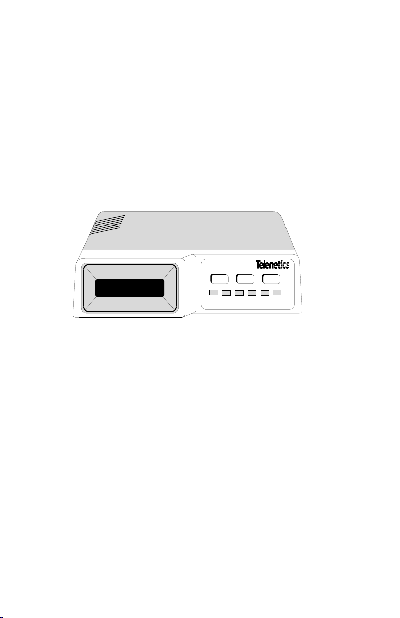
Front Panel
Three front panel pushbuttons, YES, NO, and HOME, enable user input.
A front panel 32-character LCD allows menu driven user operation and
real time unit status displays. DTE signal status can be monitored by six
LEDs and the LCD on the front panel (Figure 1-1).
NO
YES
TM
ALM
LOS
HOME
TD
CS
RD
FT 100S
Figure 1-1
Front Panel
1-2 FT 100S

Introduction
Rear Panel
The rear panel (Figure 1-2) contains a power cord, fuse, an 8-pin RJ48C
network interface connector, a 9-pin D-type interface connector for
external control, and one 25-pin D-type DTE connectors. Since the FT
100S connects directly to the T1 network, it does not include an ON/
OFF power switch.
F
3/16
AMP S.B.
250 VAC
U
S
E
E
S
U
F
F
U
S
E
DTE
NWK
115 VAC
60 HZ
1/8 AMP
CONTROL
Figure 1-2
Rear Panel
FT 100S 1-3

Introduction
FEATURES
• UDS and Telenetics LocalView Shelf compatible
• V.35 synchronous interface
• All standard data rates: n x 56 kbps, n x 64 kbps (where n = number
1 to 24 of DS0 time slots-- 1.536 Mbps max)
• Fractional T1 compatible
• Uniform synthesized DTE transmit and receive clocks
• Flexible timing options
• Integral CSU
• B8ZS clear channel capability
• ESF or SF framing modes
• ESF diagnostics per AT&T 54016 and ANSI T1.403
• Built-in network and per channel loopback test capability
• Front panel LED status display for DTE ports
• Configuration and diagnostic options via: Front panel LCD, RS-
232 control port, or Motorola LocalView
1-4 FT 100S

Chapter 2
Installation
GENERAL
This chapter provides installation information for the FT 100S. If
changing hardware options to meet system requirements, refer to
Chapter 3 before installation.
☞
Note
When requesting T1 network service, personnel operating
this equipment must complete the affidavit in the front of
this manual and file it with the telephone company
providing service.
RECEIPT INSPECTION
Inspect the equipment carefully for damage that may have occurred in
shipment. If there is damage or material shortage, contact the shipping
agent and Telenetics authorized agent for advice and assistance. Retain
the shipping container and packing material for possible future shipment.
The FT 100S arrives with the following components:
• Standalone housing containing two main circuit boards
• Two user specified piggyback interface boards/adapters
• Power transformer with cable
• T1 line cables
• V.35 adapter (included with V.35 unit)
• User's Guide
The following components must be supplied by the user:
• RS-449 adapter
• Control port adapter
FT 100S 2-1
Installation
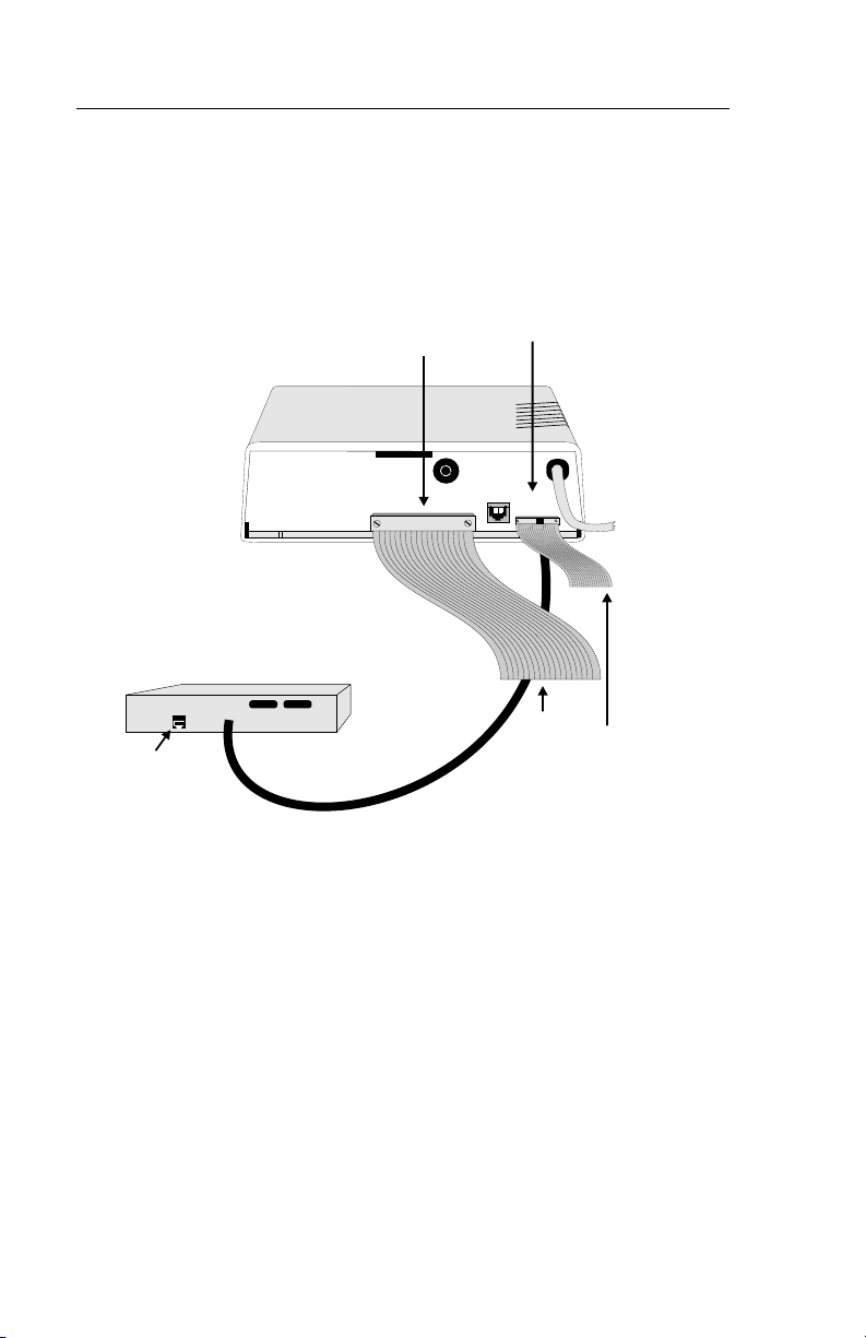
SITE PREPARATION
The installation area should be clean, well-lighted, and free from
extremes of temperature, humidity, appreciable shock, and vibration.
Allow sufficient space at the rear of the unit for cable clearance and air
flow. See Figure 2-1.
CONTROL
Port
F
U
E
S
U
F
S
E
115 VAC
S
E
F
U
60 HZ
1/8 AMP
NWK
CONTROL
DTE
Cable
Control
Terminal Cable
RJ48C
Jack
PORT 1
DTE Connector
3/16
AMP S.B.
250 VAC
Figure 2-1
Installation
2-2 FT 100S

Installation
CONNECTIONS
☞
Note
Before connecting the unit to the network or the DTE, determine whether the factory setting for Network Transmit LBO
is set as required or must be changed. Refer to Chapter 3.
FT 100S to Network
Network T1 line connections are made through a standard 8-pin RJ48C
jack labeled NWK on the rear panel. Table 2-1 list pin connections for
the network connector.
To connect the unit to the network,
Table 2-1. Network Connector Pin Functions
RJ48C Pin Function
1 Network receive ring (R1)
2 Network receive tip (T1)
3 Not used
4 Network transmit (R)
5 Network transmit (T)
6 Not used
7, 8 Ground
1. Insert one end of the supplied cable into the unit's NWK jack.
2. Insert the other end into the RJ48C on the T1 Network interface connector.
FT 100S 2-3

Installation
FT 100S to Remote Control Device
The 9-pin D-type male connector labeled CONTROL on the rear panel
connects to the terminal that controls FT 100S operation, or to a modem
connected to a remote terminal that controls the unit.
The interface is compatible with EIA RS-232 serial data operation and
has pin functions like a DCE interface.
This is the same type of connector with the same pin connections as
found on IBM PC/AT personal computers and compatibles so that standard cables can be used.
Pin connections for this interface are shown in Table 2-2.
Table 2-2. Control Port Connector Pin Functions
DB9 Pin Function
1 Data carrier detect
2 Receive data
3 Transmit data
4 Data terminal ready
5Ground
6 Data set ready
7 Request to send
8 Clear to send
9 Not used
To connect the unit to the network,
1. Insert one end of the cable into the unit's CONTROL port.
2. Insert the other end into the RS-232 connector on the controlling equipment.
2-4 FT 100S

Installation
FT 100S to DTE
The 25-pin D-type female connector on the rear panel connect to the
DTE. Table 2-3 and Table 2-4 show pin connections for the optional
DTE connector available.
To connect the unit to the DTE,
1. Insert the DTE cable into the DTE connector on the unit.
2. Insert the opposite end into the designated DTE.
3. Secure the screws to complete the connection.
V.35 Adapter Installation
The V.35 adapter is provided with the FT 100S. Optional adapters are
available for converting the DTE connector to a 34-pin V.35 type
connector or to a 37-pin RS-449 type connector. You can use the
RS-449 adapter. The RS-449 adapter is not provided with the FT 100S.
Pin connections for the V.35 and RS-449 adapters are listed in Table 2-3
and Table 2-4.
Table 2-3. RS-530 / RS-449 Pin Functions
RS-530
(DB25) Pin
1 1 Protective ground
2 4 Transmit data A
3 6 Receive data A
4 7 Request to send A
5 9 Clear to send A
6 11 Data set ready A
7 19 Signal ground
8 13 Receive line signal detect A
9 26 Receive clock B
10 31 Receive line signal detect B
11 35 External transmit clock B
12 23 Transmit clock B
13 27 Clear to send B
RS-449
(DB37) Pin
Function
FT 100S 2-5

Installation
Table 2-3. RS-530 / RS-449 Pin Functions (Continued)
14 22 Transmit data B
15 5 Transmit clock A
16 24 Receive data B
17 8 Receive clock A
18 10 Local loopback
19 25 Request to send B
20 12 Data terminal ready A
21 14 Remote loopback
22 29 Data set ready B
23 30 Data terminal ready B
24 17 External transmit clock A
25 18 Test mode
Table 2-4. V.35 Functions (Part Number 5003769-01)
V.35 (DB25)
Connector
Pin
1 A Protective ground
2 P Transmit data A
3 R Receive data A
4 C Request to send
5DClear to send
6 E Data set ready
7 B Signal ground
8 F Receive line signal detect
9-12 -- Not used
13 AA/a Transmit clock B
14 S Transmit data B
15 Y Transmit clock A
16 T Receive data B
17 V Receive clock A
18 J Local loopback
19 X Receive clock B
V. 3 5
(34 pin V.35)
Adapter Pin
Function
2-6 FT 100S

Installation
Table 2-4. V.35 Functions (Part Number 5003769-01)
20 H Data terminal ready
21 BB/b Remote loopback
22 -- Not used
23 W Ext transmit clock B
24 U Ext transmit clock A
25 K Test mode
POWER
Power is supplied through a 6-foot line cord with a grounded 3-wire
plug (attached to the unit). If chassis ground is available through the
third prong of the plug, a separate ground wire is not required.
FT 100S 2-7

Installation
2-8 FT 100S

Chapter 3
Hardware Configuration
GENERAL
The FT 100S is factory configured to current industry standards.
Because of the number of possible applications, the unit will require
some option changes to fit a particular application.
This chapter describes the options that are configured with hardware on
the printed circuit board (PCB). Hardware options are selected by two
plug-on straps, a dip switch, and installing the interface adapter card. To
access these options on the standalone unit, the cover must first be
removed.
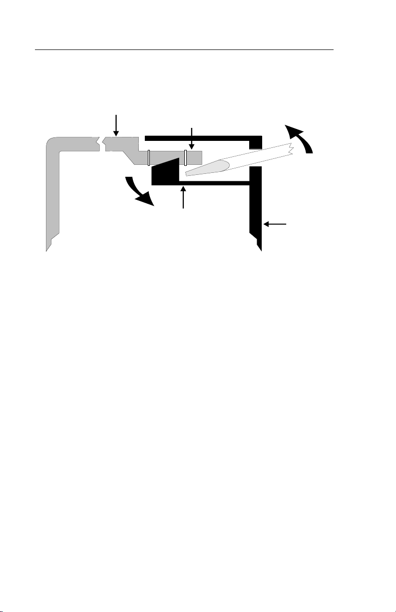
COVER REMOVAL
Warning
Do not remove the cover unless the power cord is
unplugged.
1. Place the unit on its side on a flat surface.
2. Insert a medium size flat screwdriver blade in one of the
bottom rear latch slots. Do not push the screwdriver but
lightly pry the handle away from the unit as shown in
Figure 3-1. This disengages the lock prong from the latch
locks.
3. Assist removal by pushing the cover from the chassis with
your fingers on the unit rear edges. Repeat this procedure
with the remaining latch slots.
4. To replace the cover, align the latch locks, rear guide grooves, and front lock tabs.
5. Press the cover in place until the latch locks engage the lock prongs.
FT 100S 3-1
Hardware Configuration
Cover
Lock Clip
Lock Prong
Chassis
Bottom
Figure 3-1
Cover Removal
CHANGING OPTION SETTINGS
Figure 3-2 shows the positions of the option straps, the dip switch, and
the interface adapter card on the main PCB. Figure 3-3 shows a typical
strap application.
• To change a strap setting, lift the jumper strap off and insert it in the
new position.
3-2 FT 100S
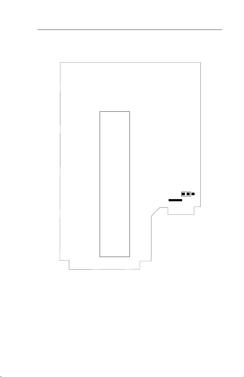
DTE PORT 1
INTERFACE
ADAPTER
CARD
Hardware Configuration
E1
Figure 3-2
Strap and Adapter Card Locations
FT 100S 3-3

Hardware Configuration
2
1
3
E1
E1
Strap Application
Grounding
Signal ground is normally separated from chassis ground. If necessary,
signal ground can be connected to chassis ground by moving the strap to
E1.
DTE INTERFACE OPTIONS
Several standard DTE interfaces are available.
Normally, the FT 100S is purchased with the required interface already
installed. However, if application requirements change, the unit can be
reconfigured.
The DTE interface type is selected by
• installing the appropriate adapter card onto the main printed circuit
board and
• if required, installing an adapter for converting the DTE connector
on the rear panel.
=1
Figure 3-3
Installing an Interface Card
The interface adapter card is located on the main printed circuit card as
shown in Figure 3-2.
To remove a card, remove the stand off screws and carefully lift both
ends of the card vertically to unplug the card.
3-4 FT 100S

Hardware Configuration
Since the available interface adapter cards are used on various Telenetics products, they may contain switches and straps that must be set
according to the product on which they're to be used. For the FT 100S,
the settings are described in the table below. Option cards that were
installed at the factory should already be configured properly.
V.35 Card RS-530/449 Card
#4563699 or 4563956 #4563507 #4563137
Switches 3, 4, 6 ON
1, 2, 5, 7, 8, OFF
Strapped for
CHNL
Strapped for
TM
To install a card,
1. Ensure the card is configured correctly
2. Align the connectors
3. Firmly press the adapter card down at both ends until the card fully seats, and
4. Re-install stand off screws.
Using a Conversion Adapter
A V.35 or RS-449 connector conversion adapter can be attached to the
rear panel DTE connector. These adapters convert the existing 25-pin Dtype DTE connector to a 34-pin V.35 connector or 37-pin RS-449
connector.
FT 100S 3-5

Hardware Configuration
3-6 FT 100S

Chapter 4
Front Panel Option Selection
GENERAL
FT 100S configuration options, operating status, and diagnostics can be
observed or changed using the front panel pushbuttons with the LCD.
The unit can also be controlled by the control port described in
Chapter 6, or by the LocalView terminal when installed in the LocalView shelf.
LCD MENUS
Three main menus provide
• Port status displays
• Diagnostic options
• Configuration options
Each main menu is supported by submenus, items, and options.
While most menu items allow selecting different options, some only
display the current status of a signal or function. These provide status
monitoring for such features as receive signal frame synchronization
and alarm reporting.
Table 4-1 lists all menus.
Using the Pushbuttons to Select Options
Generally, pressing NO scrolls vertically down the columns in Table 4-1
and pressing YES advances horizontally across the columns. Pressing
HOME returns to the submenu or main menu header. If the pushbuttons
are pressed and held, the FT 100S automatically scrolls through the
menu at a rate of about 4 display advances per second. Options are
selected by pressing the YES/NO pushbuttons in answer to prompts or
questions. In some cases, option fields on the LCD blink. If this occurs
and the displayed selection for the option should be changed, press NO
to display another selection. If the displayed selection is the setting
required, press YES to select it and advance to the next option field or
submenu.
FT 100S 4-1

Front Panel Option Selection
Table 4-1. Menu Options
MAIN
MENU
M
Port
A
Status
I
Display?
N
1
M
Diagnos-
A
tic
I
Options
N
2
M
Configu-
A
ration
I
Options?
N
3
SUBMENU SUBMENU ITEM OPTION
Line Status: Mode / Line Code /
Port 1 Status Mode / Interface /
T1 Tests? T1 Local Loopback? YES / NO
DTE Port Tests? Local Terminal
Monitor DS0
Display
Performance
History
Display?
T1 Line
Options?
Framing / Receive
Status
Data Rate
T1 Network
Loopback?
Remote CSU
Loopback?
Loopback?
Remote Terminal
Loopback?
Remote Loopback? YES / NO
Remote Loopback
with Test Pattern
Test Pattern Test? YES / NO
Channel Data
## nnnnnnnn
Error Free Seconds? nn% (0-100)
Error Events: nn (0-65565)
24 Hours Total? ES / BES / SES /
15 Minute Interval
Data?
Framing SF / ESF *
Line Code AMI * / B8ZS
Bit Stuffing Enable
ESF (PRM)
Transmission
YES / NO
YES / NO
YES / NO
YES / NO
YES / NO
channels 1-24
UAS / LOFC / LCVS
(1-900 each)
Disable *
Enable
Disable *
4-2 FT 100S
 Loading...