

Telemetrics PT-HP-S4 Operation Manual
Operation Manual
HP Servo P/T Head (48V)
Model PT-HP-S4
92 56156 000
P/N 92 56156 000-11 Rev. A
6 Leighton Place
Mahwah, New Jersey 07430
www.telemetricsinc.com

Table of Contents
1.0 Scope.....................................................................................................................1
2.0 Introduction ............................................................................................................1
3.0 Specifications......................................................................................................... 2
4.0 System Cables....................................................................................................... 3
4.1 Power Cable...................................................................................................................................................3
4.2 Serial Data Connection..................................................................................................................................3
4.3 Auxiliary Connections................................................................................................................................... 4
5.0 Camera Power & Camera Control..........................................................................4
6.0 Lens Interface Information...................................................................................... 8
7.0 Connector Input/Output Signals ............................................................................. 9
8.0 PC Boards............................................................................................................ 13
APPENDIX A Telemetrics Serial Data Protocol.............................................................15
APPENDIX B Controller Board 53915 DIP Switch Setting............................................ 28

List of Figures
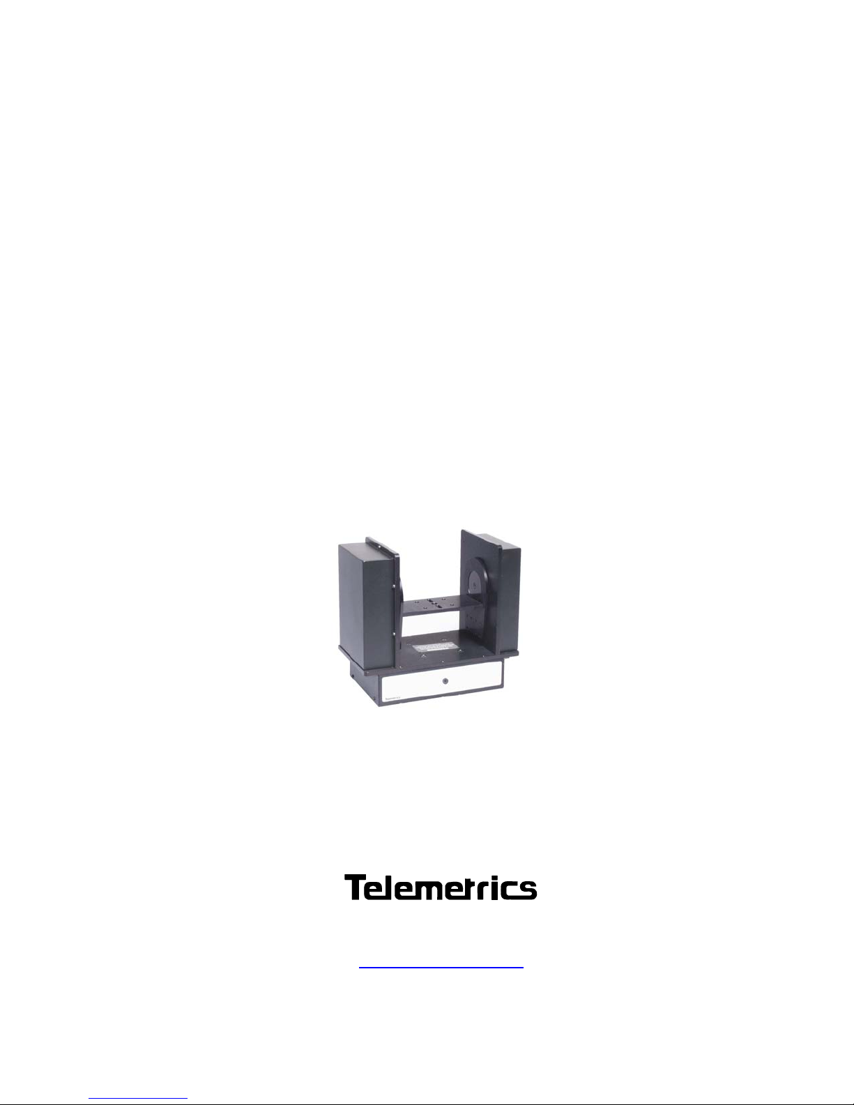
Figure 1. Pan/Tilt Head..................................................................................................1
Figure 2 Power Cable CA-PWR-7XLR- XXX ................................................................3
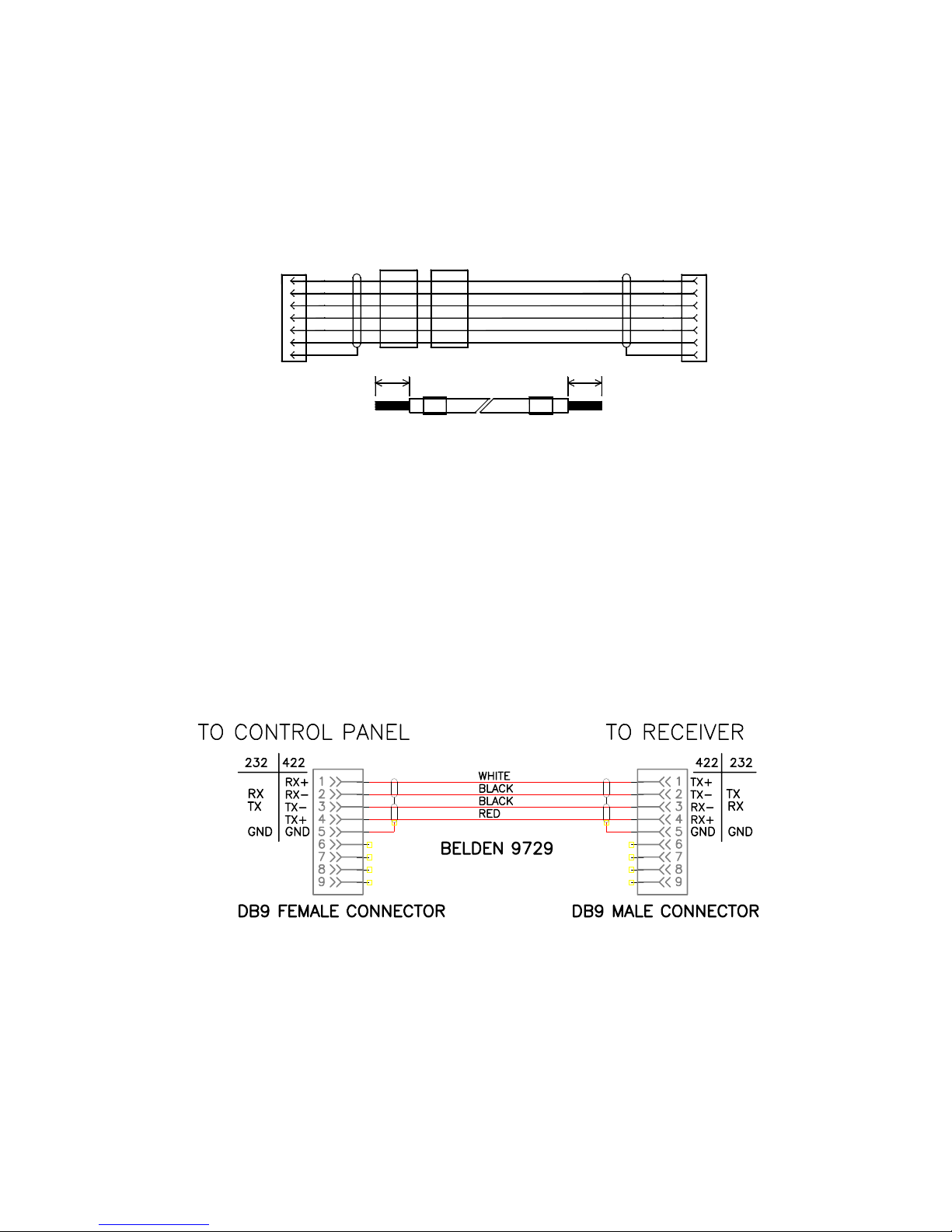
Figure 3 Serial Data Cable........................................................................................... 3
Figure 4. Trolley/Televator Cable CA-S2-AUX.............................................................4
Figure 5 Sony DXC-950/990 Power Cable ................................................................... 5
Figure 6 Sony DXC-950/990 Data Cable ...................................................................... 5
Figure 7 Sony DXC-950/990 Power/Data Cable........................................................... 6
Figure 8. Panasonic AW-E600/800 Power Cable ........................................................6
Figure 9. Panasonic AW-E600/800 Data Cable ...........................................................6
Figure 10. Panasonic AW-E600/800 Power/Data Cable..............................................7
Figure 12. Hitachi HV-D15 Power/Data Cable ............................................................. 7
Figure 13. Hitachi Z-3000W Power Cable.................................................................... 8
Figure 14. Hitachi Z-3000W Power/Data Cable ........................................................... 8
LITHIUM BATTERY CAUTION, Danger of explosion if the internal lithium battery
is replaced incorrectly. Replace only with the same or equivalent type
recommended by the manufacturer. Dispose of used batteries according to the
battery manufacturer’s instructions.
The Lightning Flash With Arrowhead symbol, within an equilateral triangle,
alerts the user to the presence of uninsulated dangerous voltage within the
product’s enclosure that may be of sufficient magnitude to constitute a risk of
electric shock.
The Exclamation Point symbol, within an equilateral triangle, alerts the user to
the presence of important operating and maintenance (servicing) instructions in
product literature and instruction manuals.
1.0 Scope
This manual contains information for the Telemetrics HP Servo Pan/Tilt Head Model
PT-HP-S4, Part No. 92 56156 000. This Pan/Tilt is designed for use with ENG and
smaller type cameras. Due to the different types of cameras and lenses the
Pan/Tilt interfaces with, many options are manufactured. Some of those options
are described in the following paragraphs. Please consult the factory for the
specific options available.
2.0 Introduction
The PT-HP-S4 is a robotic camera pan/tilt head with smooth variable operating
speed. Heavy duty cross roller bearings and swings motors with isolation mounts
provide quiet operation. The lens connector provides direct connection and
interface to lens functions. Lens interface options are also available. The Pan/Tilt
head is powered from the Rack Mount Power Supply PS-RM-48 and converts the
48V to appropriate voltage levels for the head, auxiliary robotics devices, camera,
lens and viewfinder.
The unit is controlled through serial data interface using RS-232 standard or RS422 optional or 10/100 BASE-T Ethernet connections. Manual smooth motion is
accomplished using velocity servo controls. Two hundred and fifty five (255)
presets are available. Presets are called using shot convergence technology,
allowing for smooth motion like presets. An optional camera control feature is
available for certain cameras. It has Tally LED on front panel to indicate camera
“On Air”.
The PT-HP-S4 is typically controlled by a Telemetrics Rack Serial Control Panel
(CP-R-3A or CP-R-2A), Desktop Serial Control Panel (CP-D-3A or CP-D-2A) or
Remote Control Panel (RCP). Second party RS-232/422 control systems can also
be used to interface with the unit. Please consult factory for configuration
assistance. See Appendix A for Serial Protocol specifications.
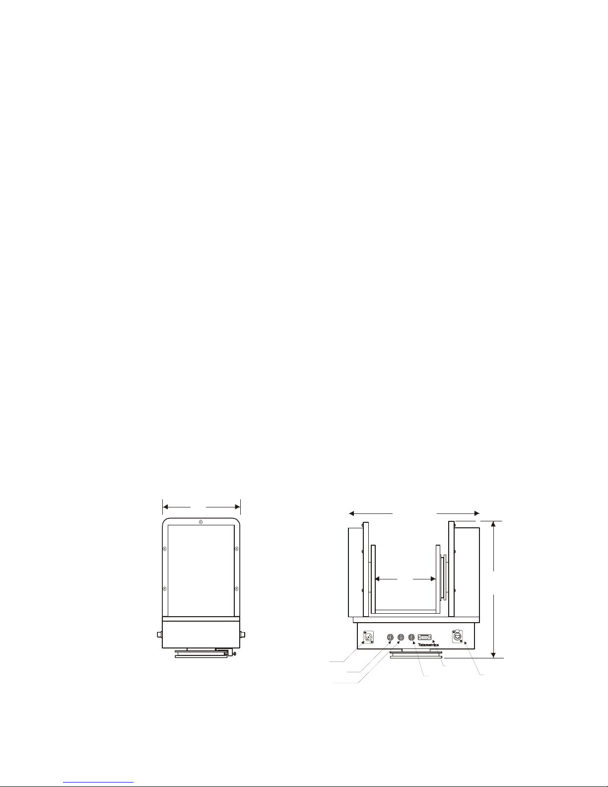
6"
12.505"
7"
10"
DC POWER
CAMERA LENS AUX SERIAL
ETHERNET
Figure 1. Pan/Tilt Head
Power
Cam Ctl
Lens
Aux
Serial
Ethernet
1

3.0 Specifications
Input voltage 38-53VDC
Input current 6.8 A max
Input Power 50 W
(P/T head only)
Input Power Conn. 7-pin Male XLR
Camera Power 40 W (13.5 VDC, 3 A max)
Pan travel ±170° w/endstops, ±200° w/o endstops
Tilt travel ±35° (+35°, -90° PTO-HP-S4-EA)
*End stops Resolution Continuous Angular Adjustable – Abrupt Stop
Electronic: Smooth Stop
*Min/Max pan velocity 0.01° - 25°/sec (40°/sec High Speed PTO-HP-S4-HS)
*Min/Max tilt velocity 0.01° - 25°/sec (40°/sec High Speed PTO-HP-S4-HS)
Stopping Accuracy ±5 arc min/0.08°
Audible Noise 37 dB(A) max, IEC Free Field
Operating Modes 32 bit velocity and positional servo control
Preset position with multi-axis convergence
Mounting Upright or inverted
Dynamic Load 35 lbs. max. (16 kg)
Weight 14 lbs. (6.3 kg)
Dimensions 10” H x 11 ¼” W x 6” D
18”H x 11 ¼” W x 6” D (Extended Yoke)
14 ½”H x 11 ¼” W x 6” D (Extended Arms)
* End stops are set to ±170° Pan and ±35° Tilt unless otherwise specified by customer.
2
4.0 System Cables
4.1 Power Cable
Power to the unit is made via interconnect cable CA-PWR-7XLR-XXX to the
7-pin XLR power connector located on the rear of the unit (Note: XXX=Feet).
The other end of interconnect cable connects to the external power supply.
TO PWR
SUPPLY
J1
CONN 7-PIN XLR MALE
NEUTRIK - NC7MX
4.2 Serial Data Connection
RED
BLACK
BLUE
WHITE
ORANGE
1/2"
STRIP
LENGTH
QUABBIN #4177
RED
BLACK
BLUE
WHITE
BROWN
GREENGREEN6
LABEL
LABEL
+48V
+48V
+48V
RTN
RTN
RTN
1/2"
STRIP
LENGTH
SHIELD
SLEEVING
SHIELD
SLEEVING
ALPHA #25836
1
2
3
4
5
7
LENGTH: VARIABLE (CUT CABLE XXX' +5")
Figure 2 Power Cable CA-PWR-7XLR- XXX
J2
1
TO P/T
2
3
4
5
6
7
CONN 7-PIN XLR FEMALE
NEUTRIK - NC7FX
Communication to the unit is made via serial data cable CA-RS to the 9 pin
serial data connector located on the rear of the unit. The other end of the
cable connects to the control panel. Units configured for RS-232 can have a
maximum distance of 100 feet between the unit and the control panel. Units
configured for RS-422 can have a maximum distance of 4000 feet between the
unit and the control panel. (Note: Units are set to accept either RS-232 or RS422 at the factory. See Table 1 for proper DIP switch settings.)
Figure 3 Serial Data Cable
3
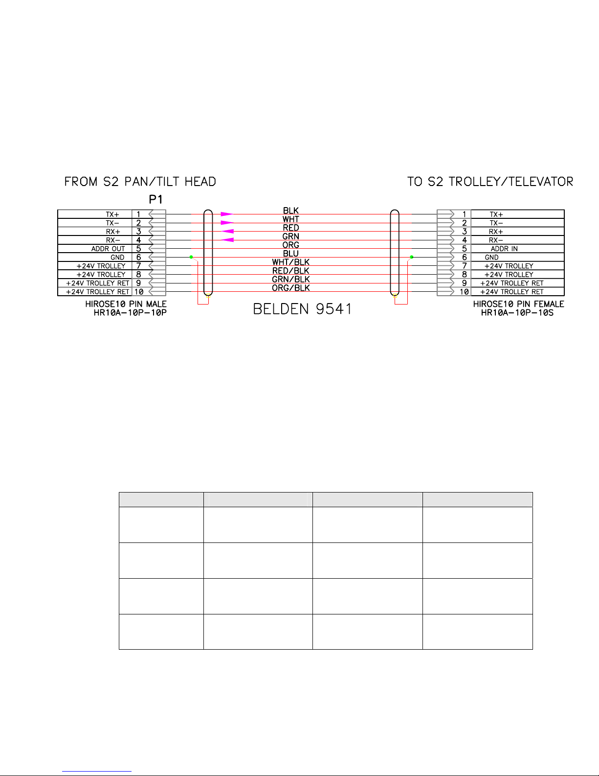
4.3 Auxiliary Connections
Power and control of the Telemetrics Trolley and Televator units is
accomplished using the auxiliary connector on the pan/tilt. It is important to
remove power from the pan/tilt prior to connecting or disconnecting the
auxiliary cable. Damage may occur if the unit is powered when connecting or
disconnecting the cable. Note: Refer to Appendix for information on Aux Axis
Soft Limit configuration.
Figure 4. Trolley/Televator Cable CA-S2-AUX
5.0 Camera Power & Camera Control
Telemetrics pan/tilt systems are capable of providing power and data to virtually all
manufacturers’ cameras. A Telemetrics power supply that includes a 15V module
for the camera must be used when camera power is required. In addition, the
Telemetrics control panel must be configured to accept the camera ROP to provide
camera control. See Table 3 for currently available accessory cables.
Table 1 Camera Power and Data Cables
Camera Power Data Power/Data
Sony
DXC-950/990
Panasonic
AW-E600/800
Hitachi
HV-D15
CA-S2-P-DXC990 CA-S2-D-DXC990 CA-S2-PD-DXC99
CA-S2-P-E600 CA-S2-D-E600 *CA-S2-PD-E600
CA-S2-P-HVD15 CA-S2-PD-HVD15
Hitachi
Z-3000W
*Note: The Panasonic Camera Control Cable requires removal of the screw
terminals on the 50 Pin connector.
CA-S2-XLR-4F CA-S2-PD-Z3000
4
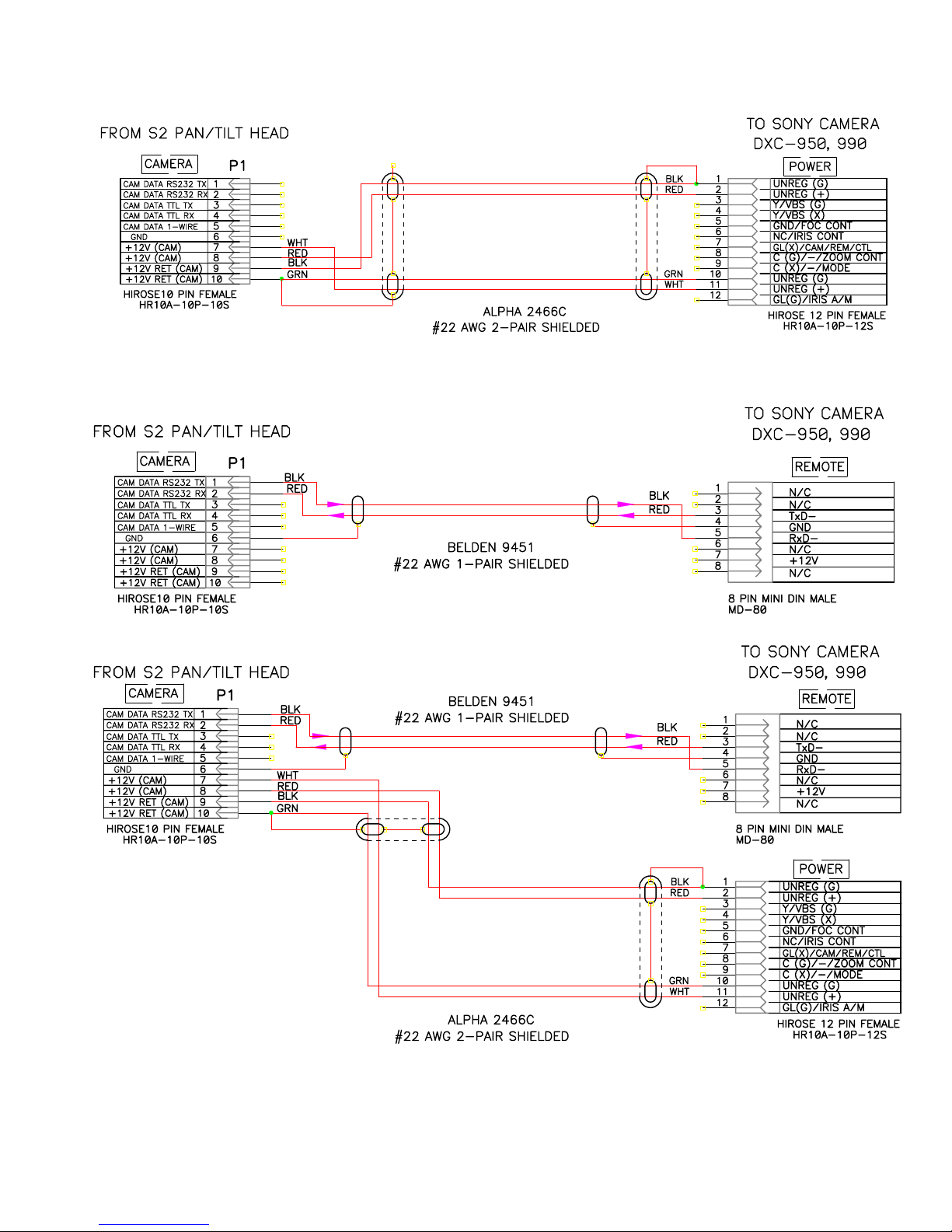
Figure 5 Sony DXC-950/990 Power Cable
Figure 6 Sony DXC-950/990 Data Cable
5
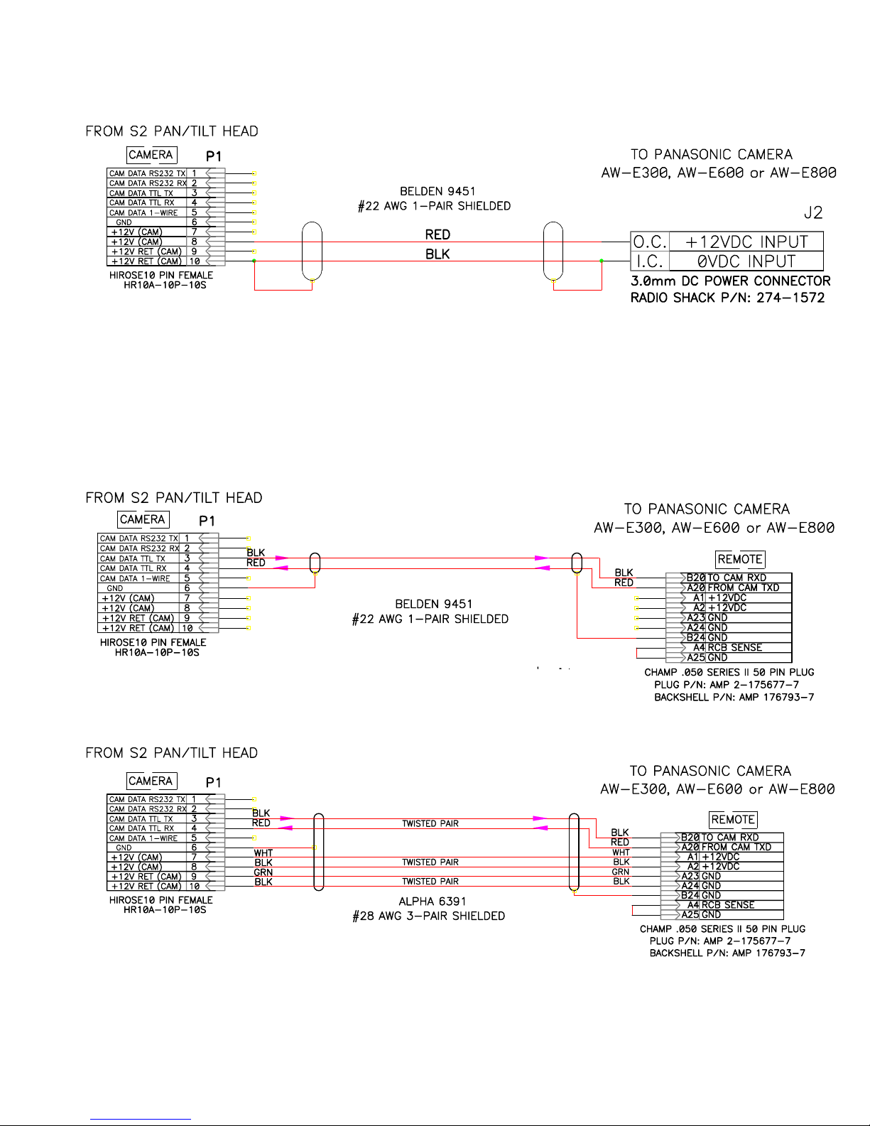
Figure 7 Sony DXC-950/990 Power/Data Cable
Figure 8. Panasonic AW-E600/800 Power Cable
Figure 9. Panasonic AW-E600/800 Data Cable
6
 Loading...