

Telemetrics CP-RMR-S, CP-RMR-S 92 50939 000 Operation & Installation Manual

Operation & Installation Manual
Serial Receiver
Model CP-RMR-S
92 50939 000
P/N 92 50939 000-11

Table of Contents
1.0 Scope .....................................................................................................................2
2.0 Introduction.............................................................................................................2
3.0 Specifications .........................................................................................................2
4.0 Control Commands...................................................................................................3
5.0 Installation and Hook-up...........................................................................................3
6.0 Connector Function..................................................................................................7
7.0 DIP Switch Settings..................................................................................................8
List of Figures
Figure 1 Front View........................................................................................................3
Figure 2 Rear View.........................................................................................................3
Figure 3 Power Supply Cable..........................................................................................4
Figure 4 Control/Power Cable ........................................................................................5
Figure 5 Serial Data Cable.............................................................................................5
Figure 6 Typical System Hook-up Diagram....................................................................5
Figure 7 DIP Switch Settings for Lens Function and Baud Rate....................................8

1.0 Scope
This manual contains installation and operational information for the Telemetrics
Serial Receiver Model CP-RMR-S, Part No. 92 50939 000. The unit is a pan/tilt
and lens controller that can be used with up to four cameras.
2.0 Introduction
The CP-RMR-S is a serially addressable pan/tilt and lens controller. It receives
RS-232 or RS-422 input commands from either a control panel or computer.
The output signals are used to control pan, tilt, zoom and focus servos for up to
four robotic camera control units and cameras. These functions can operate in
proportional mode or in preset mode. The unit incorporates external DC power
and control signals for the pan/tilt onto one cable. Optional output functions such
as Iris Control and Trolley Control are also available.
3.0 Specifications
Communications RS-232 or RS-422 bi-directional serial port
300-38,400 BPS (9600 default), 8 bits, no parity,
1 stop bit
Proportional Control 15 bit resolution
Simultaneous control of pan, tilt, zoom and focus
Operating Modes Open loop (proportional velocity) or closed loop
(positional)
Preset Control 16 Presets per camera
±0.25° error (12 bit resolution)
Preset Feedback Voltage 0 to 10VDC nominal (up to ±170° Pan and Tilt)
Weight 9 lbs. (4 kg)
Dimensions 19 “W x 1¾”H x 12½”D
Power 120 VAC, 10 Watts
2
4.0 Control Commands
Control is accomplished by sending commands consisting of ASCII characters
terminated by an ASCII carriage return (<CR>, hex 0D). In most cases, several
commands may be sent together on the same line before sending the <CR>.
However, in the case of the recall preset command, other commands may
precede it but any commands following it on the same line are ignored. A
command line will not be executed until the <CR> is received. ASCII backspace
(<BS>, hex 08) can be used to correct errors in the command line. After the
command line has been executed, a <CR> will be sent back to the host to
acknowledge completion.
Communication rate is 9600 BAUD. Protocol is 8 data bits, one stop bit, and no
parity.
5.0 Installation and Hook-up
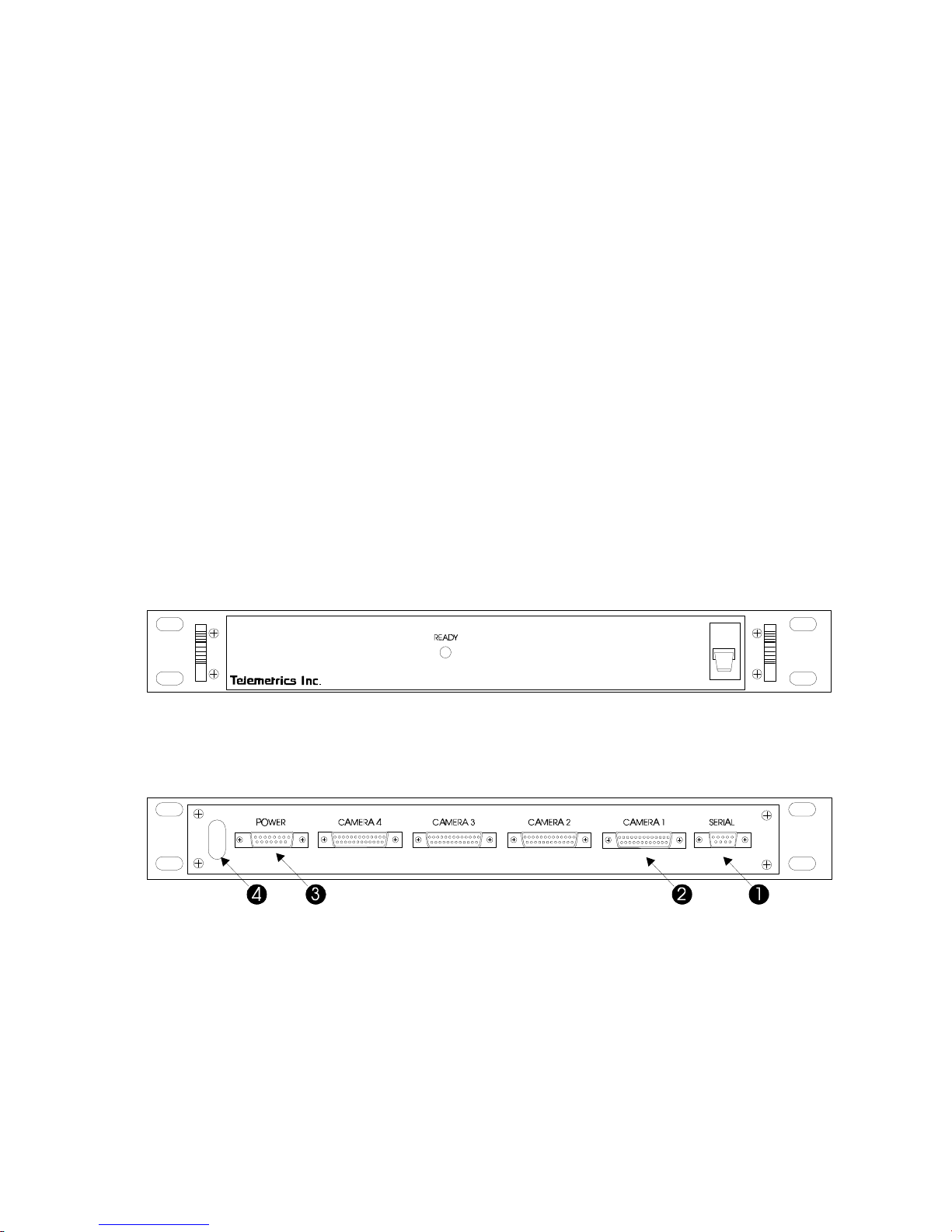
The Serial Receiver is designed to mount directly into a 19-inch rack
configuration. The front of the unit has an AC power switch and a Ready light.
The light will illuminate when the power switch is turned to the on position and
the unit boots up. See Figure 6 for a typical system hook-up diagram.
Figure 1 Front View
There are six connector ports on the rear of unit which are identified below:
Figure 2 Rear View
1. Serial Communication (9 D-sub female connector)
2. Camera Interface Port (25 D-sub female connector)
3. Pan/Tilt power input (15 D-sub male connector)
4. 120 VAC power cord
3
Power to the head is made via interconnect cable 69083 (figure 3) to the 15 D-
1
9
W
I
R
E
S
I
D
E
1
5
D
M
a
l
e
T
o
P
o
w
e
r
S
u
p
p
l
y
8
1
5
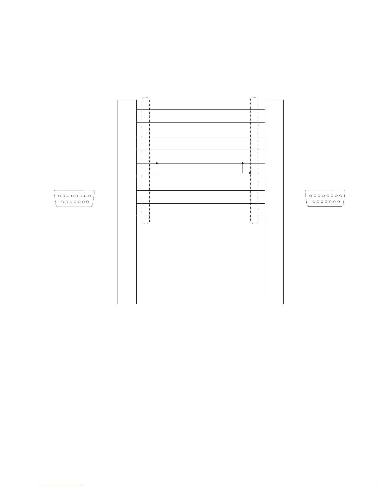
sub connector on the rear of the unit. The configuration of the power supply
(single, dual, triple or quad) depends on how many pan/tilt heads are being
controlled. The other end of interconnect cable connects to the external power
supply.
To Preset Panel
1
9
WIRE SIDE
8
15
15 D Female
1
2
3
4
5
6
7
8
9
10
11
12
13
14
+15V
+15V RET
+15V
+15V RET
+15V
+15V RET
+15V
+15V RET
Not Used
1
2
3
4
5
6
7
8
9
10
11
12
13
14
15
Figure 3 Power Supply Cable
15
4
 Loading...