

Page 1
Copyright TeleMatrix Inc 2008
®
3302TRM
2 LINE TRIMLINE
TELEPHONE SET
USERS GUIDE
Page 2

INTRODUCTION
be sure to read the contents in this
Congratulations on the purchase of your
TeleMatrix 2-line Trimline telephone.
This telephone is a precision electronic
device designed and manufactured with
the highest quality components and workmanship that requires minimum maintenance.
Please
user’s guide to become familiar with
its features and functionality.
1
Page 3

CONTENTS
Table Of Contents
Introduction
Features
Controls
Definition Of Controls
Installation
Parts Checklist
Wall Mounting
134
567
10
Switch Setting 12
Operation
15
Care & Maintenance 16
Service 17
Warranty 19
2
Page 4

FEATURES
Two Line Operation
Tone Dialing
Message Waiting Lamp
Convenient Data Port
Hold Key
Line Status Indicators
Handset Volume Control
Flash Function (100mS/300mS and 600mS)
Dial In Handset
Last Number Redia
l
Hi/Low Ringer Volume Control
Desk or Wall Mountable
Hearing Aid Compatible
Fully Modular
3
Page 5
CONTROLS
4
Page 6

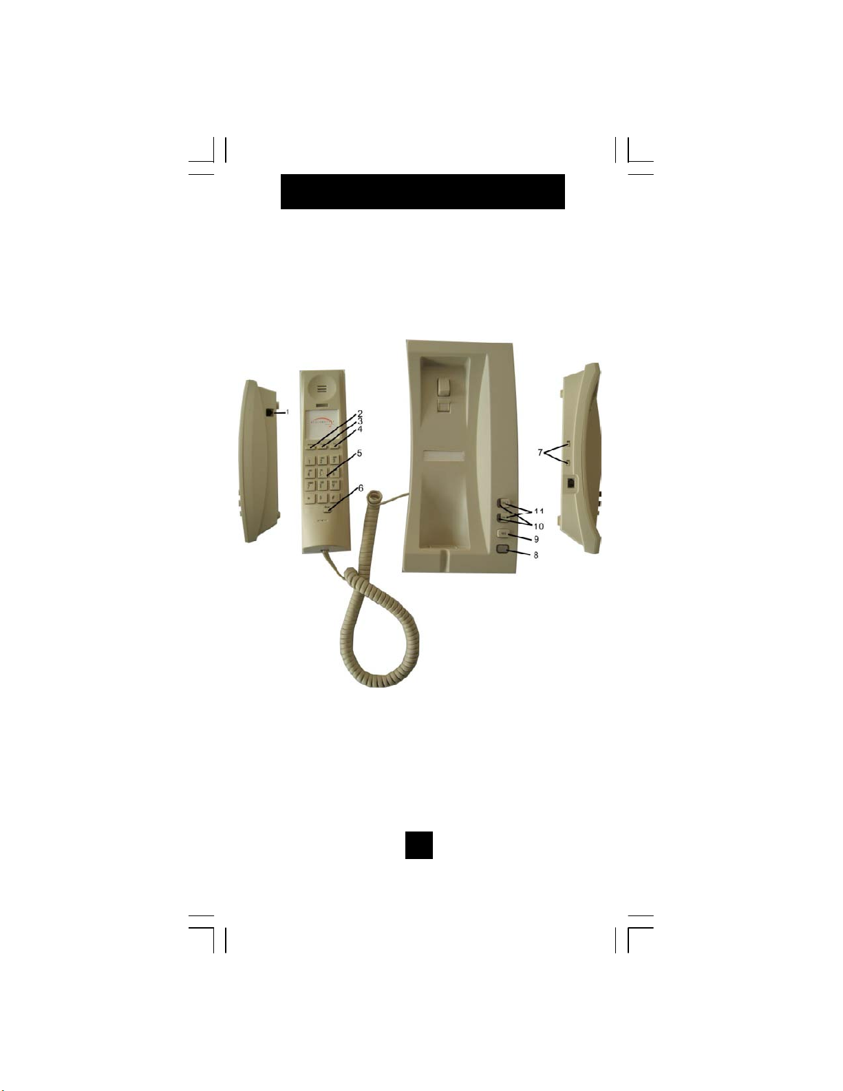
DEFINITION OF CONTROLS
1. Dat
a Port
Used for plugging in a laptop, modem, fax, etc.
2. Redial key
Used to automatically redial the last number dial.
3.
Flash Key
Provide 100mS/300mS and 600mS time line break.
4.
Handset Volume Control
Amplifies the volume of the receiver
5.
Dial Pad
Large keys used for outbound dialing.
6.
Line Reset Key
Used to reset the line to place another call.
7.
Ringer Volume Control
Switch to adjust the loudness of the ringer.
8. Message Waiting Lamp
Visual indicator to tell you that a mes
sage is waiting
or that the line is ringing.
9.
Hold Key
Used to place a caller on hold.
10. Line Status Indicator
LED indicators to show that the line is ringing,
in-use or on hold
11. Line Selector Keys
Used to select Line 1 or Line 2 when plac
ing or
answering a call
5
Page 7

INSTALLATION
Caution
Never install telephone wiring during a lightning
Use caution when installing or modifying
telephone lines.
6
storm.
Never install telephone jacks in wet location
unless the jack is specifically designed for wet
locations.
Never touch none insulated telephone wires or
terminal unless the telephone line has been
disconnected at the network interface.
Page 8

1. 15’/4.5mlinecordsoldseperately
2. RJ11C/WLineCord-3.5/.09m
3. HandsetCoilCord-10’/3.05m
Page 9

INSTALLATION
line cord into the receptacle on t
Connecting The Line Cord
Plug one end of the 15-foot modular telephone
he bottom of
the base unit. Route the cord through the cord
channel provided. Plug the remaining end of
the line cord into a standard telephone outlet.
BASE UNIT
8
Page 10

INSTALLATION
Connecting The Handset Cord
Plug one end of the modular coiled handset
cord into the receptacle located on the left
side of the base unit. Plug the remaining end
into the receptacle on the handset.
9
Page 11

The TeleMatrix Trimline telephone can be wall
mounted to a standard telephone wall jack plate.
Using the 3.5-inch line cord, plug one end into
the receptacle on the bottom of the base unit. The
remaining end will plug into the wall jack. Carefully
align the slots on the bottom of the base unit with
the wall mount studs on the jack plate. Once aligned,
slide the base unit onto the studs and snap the base
unit into place.
3.5” CORD
Page 12

INSTALLATION
telephone. Turn the “wall m
Handset Retaining Clip
The handset retaining clip must be activated to
hold the handset when wall mounting the
ount clip” 180 degrees.
Turn
11
Page 13

SWITCH SETTINGS
Flash Switch
There is a 3-position slide switch located on
the handset under the plastic cover. Use a sharp pointer
to remove the switch plastic cover plate to expose the
switch.
The FLASH KEY can provide 100ms/300ms and
600ms time line break. After setting the switch, hang
up and then remove the handset from it’s cradle to
activate new switch position.
12
Page 14

SWITCH SETTINGS
Ringer Volume Control Switch
There are two (2) slide switches located on the left
side of the base unit that is used to adjust the loudness
of the ringing sound. A “low” and “high” setting
are provided . Select the desired loudness by sliding
the switch to the appropriate position.
13
Page 15

SWITCH SETTINGS
There are two (2) slide sw
signaling, and also to “low
nnects the MWL circuit
Message Waiting Switch
itches located on the
base unit under a plastic cover. Use a sharp pointer to remove
the switch plastic cover plate to expose the two switches.
These switches control how the message-waiting
lamp (MWL) works:
Position: Mode:
TYPE Responds to “high-voltage” (neon type) MWL
-voltage”
(LED type) MWL signaling
LR1 Reverse polarity MWL, polarity 1
LR2 Reverse polarity MWL, polarity 2
The second switch (On/Off) enables the MWL when
switched on, but completely disco
when switched off.
The default Message Waiting switch settings should be:
Message Waiting ON/OFF switch needs to be set to “ON”.
Message Waiting TYPE/LR1/LR2 switch needs to be set
to “TYPE”.
14
Page 16

OPERATION
green (in
C. Receiving A Call
A. Line Status Indicators
The 2-line TrimLine is equipped with LED
indicators to show the current status of the
telephone lines. They are :
Ringing Line: LED is blinking red
Line In-Use: LED is steady green
Line On Hold: LED turns from green (in-use)
to red (hold) on telephone that places the
call on hold. All remote extensions show
-use)
B. Placing A Call
Press either Line 1 or Line 2 selector key that
does not show a green in-use indication.
Lift the handset.
Dial out using the numeric dial pad.
On an incoming call, the telephone will ring
and the line status indicators will show blinking
red.
Select the line key for the line that ringing
Lift the handset.
D. To Place A Call On Hold
Press the Hold key. The call will automati-
cally be placed on hold. The line status indicator will turn from green to red.
Hang up the handset.
To return to the held call, select the appropri-
ate line key and lift the handset.
Note: The telephone has an electronic hold
feature. The call on hold can be released from
a remote extension
15
Page 17

CARE & MAINTENANCE
cuits. Do not touch the unit if submerged in
perature environments. temperature extremes can
Keep the telephone dry. If it gets wet on the outside, wipe it dry immediately. Liquids might con-
tain minerals that can corrode the electronic cir-
water.
Call for assistance.
Use and store the telephone only in normal tem-
shorten the life of electronic devices, damage bat-
teries, and distort or melt plastic parts. Avoid direct
sunlight.
Keep the telephone away from excessive dust and
dirt that can cause premature wear of parts.
Wipe the telephone with a damp cloth occasionally to keep it looking new. Do not use harsh
chemicals, cleaning solvents, or strong detergents
to clean the unit.
16
Page 18

SERVICE INFORMATION
www.telematrixusa.com
www.telematrixeurope.com
Buck MK12 5TW, United Kingdom
When problems arise during installation or service that
cannot be resolved using this or related documents, contact
your regional TeleMatrix PriorityCare Department,Monday
through Friday,8:30a.m.-4:30p.m.
TeleMatrix USA: 1-800-462-9446 toll free N. America,
+1 719 638 8821 direct, +1 719 638 8815 fax
TeleMatrix Europe:
+44 (0) 1908 682180 direct, +44 (0) 682189 fax
TeleMatrix Middle East:
+971 4 2676550 direct, +971 4 2677361 fax
Web Sites:
&
Many times a problem is either installation or user
related.Please contact TeleMatrix PRIOR to sending a
telephone to our service center for repair.In the unlikely
event that a factory repair is necessary:
1. Include a brief description of the problem that you are
experiencing.
2. Include a proof of purchase for a repair under warranty.
3. Send the telephone prepaid by UPS or Parcel Post, insured to:
TeleMatrix, Inc., PriorityCare Center, 5025 Galley Road
Colorado Springs, Colorado 80915 USA
TeleMatrix Europe LLC, PriorityCare Center, Unit 33,
Stratford Office Village, Walker Avenue, Milton Keynes,
TeleMatrix Middle East, PriorityCare Center, Hamriyah Free
Zone, Sharjah, U.A.E.
TeleMatrix will pay return postage on the repaired telephone.
17
Page 19

FCC REQUIREMENTS
connections. This equipment should not be used on party
pair has been made. If this is not done,
properly.
performed by our company or an authorized agent. It is the re
sponsibility of users requiring service to report the need for
Service can be facilitated through your regional TeleMatrix off
1. The Federal Communications Commission (FCC) has established Rules which permit this device to be directly connected to
the telephone network. Standardized jacks are used for these
lines or
coin lines.
2. If this device is malfunctioning, it may also be causing harm
to the telephone network: this device should be disconnected
until the source of the problem can be determined and until re-
the telephone company
may temporarily disconnect service.
3. The telephone company may make changes in its technical
operations and procedures: if such changes affect the compatibil-
ity or use of this device, the telephone company is required to
give adequate notice of the changes.
4. If the telephone company requests information on what
equipment is connected to their lines, inform them of:
(a) The telephone number that the unit is connected to.
(b) The ringer equivalence number.
(c) The USOC jack required, and
(d) The FCC Registration Number.
Items (b) and (d) are indicated on the label. The ringer equivalence number (REN) is used to determine how many devices
can be connected to your telephone line. In most areas, the sum
of the REN’s of all devices on any one line should not exceed
five (5.0). If too many devices are attached, they may not ring
Service Requirements
5. In the event of equipment malfunction, all repairs should be
-
service to our Company or to one of our authorized agents.
18
ice.
Page 20

WARRANTY
STATEMENT OF LIMITED WARRANTY
are free from defects in materials and workmanship for five(5)years after the date of purchase,and Regency branded products manufactured by TELEMATRIX,INC.are free
repair or replace the defective product or parts, or deliver replacements for defective products or parts on an exchange basis at no additional charge to the customer except as
the property of TELEMATRIX, INC. Warranties on products repaired by TELEMATRIX, INC. expire at the termination of the original warranty period.
NiCd or NiMH, used in TELEMATRIX, INC. cordless products. If a product fails this warranty during the warranty period, TELEMATRIX, INC. will, at its option, either
TELEMATRIX,INC..warrants to its [original end customer] [purchaser] that Spectrum PLUS, Marquis and RETRO branded products manufactured by TELEMATRIX,INC.
from defects in materials and workmanship for three (3) years, other than the following products for which the warranty period shall be one (1) year: handset batteries, either
set forth below.Repair parts or replacement products may be either new or reconditioned. Products or parts returned to TELEMATRIX, INC.under this warranty will become
2. Any damage resulting from improper installation, maintenance or operation of the product;
This limited warranty does not cover
1. Products or parts which are damaged, abused or misused;
7. Costs incurred by the customer in removing and shipping the product to TELEMATRIX,INC.for repair or replacement,and costs of reinstallation of the product.
6. Any product or part unless proof of date of purchase is submitted with the product when returned for warranty repair; or
3. Damage resulting from unauthorized modification or repair of the product, or from improper connection of the product to other equipment;
4. Cords, connectors and replaceable batteries;
8. Products or parts which are not owned and used by the original end user customer.
5. Damage in transit to the TELEMATRIX, INC. repair facility;
The cost and risk of loss or damage for sending the product to TELEMATRIX, INC. will be borne by the customer.
TELEMATRIX, INC. BE LIABLE TO CUSTOMER OR ANY OTHER PARTY FOR ANY INDIRECT, INCIDENTAL OR CONSEQUENTIAL DAMAGES,
INC.THE POSSIBILITY OF SUCH DAMAGES. TELEMATRIX, INC. LIABILITY FOR DAMAGES SHALL NOT EXCEED THE PURCHASE PRICE OF THE
INCLUDING, WITHOUT LIMITATION, DAMAGES OF LOST PROFITS, LOST REVENUES, LOSS OF USE OF FACILITIES OR EQUIPMENT, OR COST OF
TELEMATRIX, INC. EXPRESSLY DISCLAIMS ALL WARRANTIES EXCEPT THE LIMITED WARRANTY SET FORTH HEREIN, WHICH IS THE SOLE AND
EXCLUSIVE WARRANTY OF THE PRODUCT, AND IS IN LIEU OF ALL OTHER WARRANTIES, WHETHER ORAL OR WRITTEN, EXPRESS OR IMPLIED,
SUBSTITUTE EQUIPMENT ARISING OUT OF THE USE OR INABILITY TO USE THIS PRODUCT, EVEN IF THE CUSTOMER HAS ADVISED TELEMATRIX,
OR STATUTORY. THERE ARE NO IMPLIED WARRANTIES OF MERCHANTABILITY OR FITNESS FOR A PARTICULAR PURPOSE. THE CUSTOMER'S
SOLE REMEDY UNDER THE TELEMATRIX, INC. WARRANTY SHALL BE REPAIR OR REPLACEMENT AS PROVIDED ABOVE. IN NO EVENT WILL
other rights which vary under local law. Some jurisdictions may not allow limitations on the term of an implied warranty or exclusions or limitations of incidental or
DEFECTIVE PRODUCT.
consequential damages.
This limited warranty is non-transferable without the prior written approval of TELEMATRIX, INC. It gives the customer specific legal rights. The customer may have
19
 Loading...