

Page 1

Universal 2
Master Meter, Inc.
101 Regency Parkway
Mansfield, TX 76063
800-765-6518 Toll Free
817-842-8000 Main Line
817-842-8050 Voice Mail
817-842-8100 FAX
User
Guide
FCC ID: NTAXMETER31
Manufacturer: Telematics-Wireless Ltd.
Rev 1.0
October 21, 2010
Page 2
Master Meter, Inc.
101 Regency Parkway
Mansfield, TX 76063
800-765-6518 Toll Free
817-842-8000 Main Line
817-842-8050 Voice Mail
817-842-8100 FAX
CAUTION:
The User and the Installer should be aware that changes and modifications to the equipment
not expressly approved by Master Meter could void warranty and the user's authority to
oper ate th e equipment.
Professionally trained personnel should install the equipment.
The antenna used for this transmitter must be installed to normally provide minimum
separation distance of at least 20 cm from all persons and must not be co-located or
operating in conjunction with any other antenna or transmitter.
ATTENTION:
The digital portion of the transceiver has been tested and found to comply with the
limits for a Class B digital device, pursuant to part 15 of the FCC Rules. These
limits are designed to provide reasonable protection against harmful interference in
a residential installation. This equipment generates uses and can radiate radio
frequency energy and, if not installed and used in accordance with the instructions,
may cause harmful interference to radio communications. However, there is no
guarantee that interference will not occur in a particular installation. If this
equipment does cause harmful interference to radio or television reception, which
can be determined by turning the equipment off and on, the user is encouraged to
try to correct the interference by one or more of the following measures:
1) Reorient or relocate the receiving antenna.
2) Increase the separation between the equipment and receiver.
3) Connect the equipment into an outlet on a circuit different from that to which
the receiver is connected.
4) Consult the dealer or an experienced radio/TV technician for help.
This device complies with Part 15 of FCC Rules. Operation is subject to the
following two conditions:
(1) This device may not cause harmful interference, and
(2) This device must accept any interference received, including interference that
may cause undesired operation.
Transmission Duty Cycle
The Universal 2 unit transmission duty cycle is limited by its design not to exceed
1.0%
Page 3

Master Meter, Inc.
101 Regency Parkway
Mansfield, TX 76063
800-765-6518 Toll Free
817-842-8000 Main Line
817-842-8050 Voice Mail
817-842-8100 FAX
1 ‐ Place Setting
The Universal Dialog 3G unit can be wall
°
mounted in an external open site or within
buildings
Note:
The Universal Dialog 3G data transmission
may be adversely affected if it is installed close
to RF or EM noise generators, for example: air
conditioner units, electric generator, radio
transmitter, car parking and others. If you
encounter such problems, please consult
Master Meter Service representative for
technical assistance.
Page 4
2 – Kit Contents
Master Meter, Inc.
101 Regency Parkway
Mansfield, TX 76063
800-765-6518 Toll Free
817-842-8000 Main Line
817-842-8050 Voice Mail
817-842-8100 FAX
Quantity
1
4
4
4
1
Name
Universal Dialog 3G unit
Seal Cover
Tapping screw
Plastic masonry insert
ID label sticker for meter identity
Page 5
Master Meter, Inc.
101 Regency Parkway
Mansfield, TX 76063
800-765-6518 Toll Free
817-842-8000 Main Line
817-842-8050 Voice Mail
817-842-8100 FAX
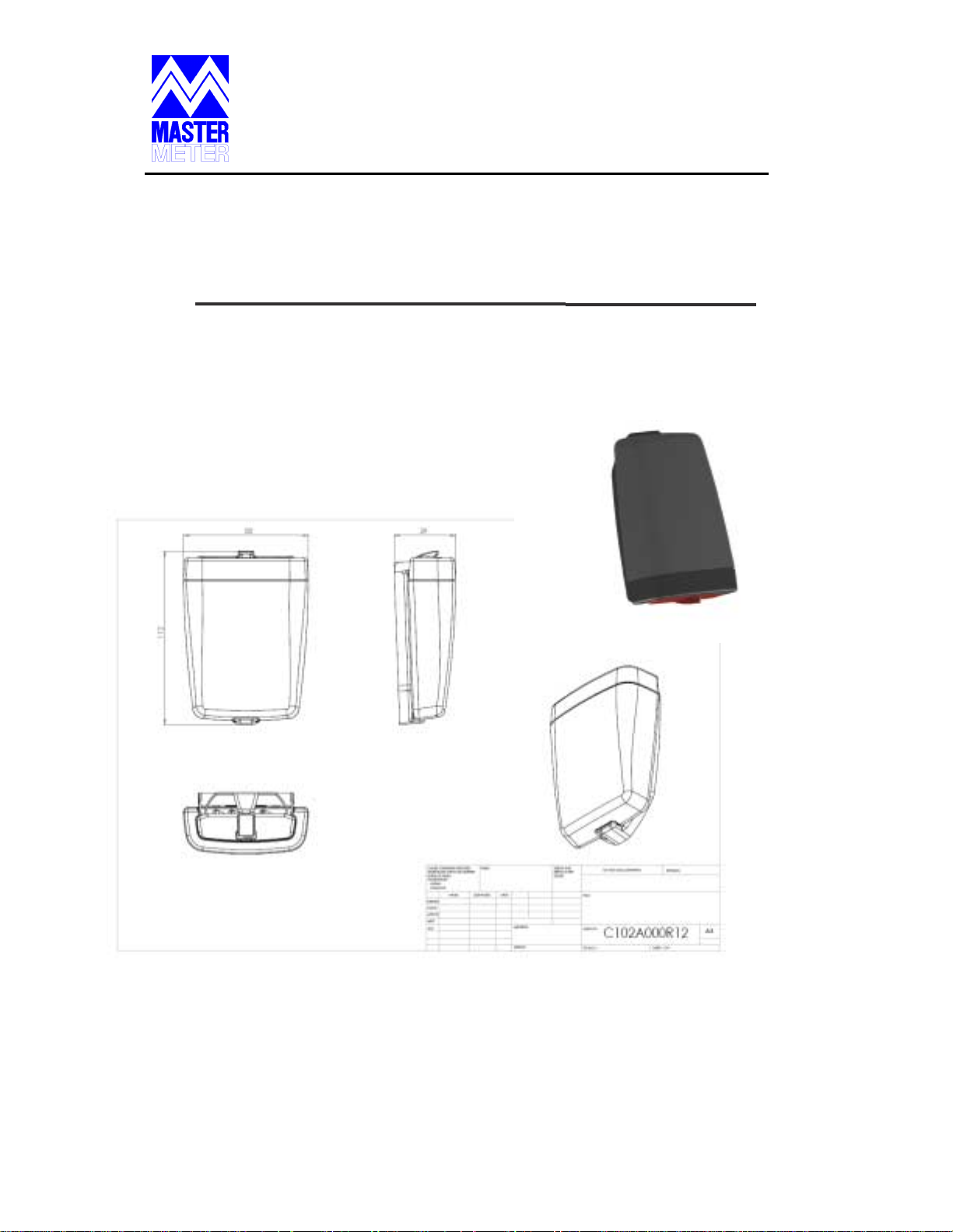
Universal Dialog 3G uni
t –Profile #1
Page 6

Master Meter, Inc.
101 Regency Parkway
Mansfield, TX 76063
800-765-6518 Toll Free
817-842-8000 Main Line
817-842-8050 Voice Mail
817-842-8100 FAX
Universal Dialog 3G uni
t –Profile #2
Page 7

Master Meter, Inc.
101 Regency Parkway
Mansfield, TX 76063
800-765-6518 Toll Free
817-842-8000 Main Line
817-842-8050 Voice Mail
817-842-8100 FAX
3 – Installation Procedure
The Universal Dialog 3G is intended for wall
installation in open sites and buildings.
1. Mark the locations of the four
screws on the wall, according to the holes
in the enclosure of the unit.
2. Drill 4 holes and insert the Plastic
masonry inserts.
3.
Connect the unit with the four
4.
5.
screw supplied.
Seal the screw holes with the
supplied screw covers.
Connect the wires of the unit
according to the connection guide in
section 4.
Page 8

Master Meter, Inc.
101 Regency Parkway
Mansfield, TX 76063
800-765-6518 Toll Free
817-842-8000 Main Line
817-842-8050 Voice Mail
817-842-8100 FAX
4 – Connection Guide
The Universal Dialog 3G can be connected to
4 outputs (2‐wire outputs).
1.
Connect the first wire in each
cable to output and the second to GND.
There is no significance to colors.
Page 9

5 – Programming
5.1 – Unit registration
Master Meter, Inc.
101 Regency Parkway
Mansfield, TX 76063
800-765-6518 Toll Free
817-842-8000 Main Line
817-842-8050 Voice Mail
817-842-8100 FAX
°
The Universal Dialog 3G is ready
use when all parameters are programmed
and the transmitter is turned on.
°
Each radio unit is supplied with
detachable bar code that should be glued
to the document that identifies the specific
meter.
Page 10

Master Meter, Inc.
101 Regency Parkway
Mansfield, TX 76063
800-765-6518 Toll Free
817-842-8000 Main Line
817-842-8050 Voice Mail
817-842-8100 FAX
5.2 – Unit Programming
Perform the Universal Dialog 3G
programming with the help of Handheld
PC+MMR‐US tool, according the following
steps:
1. Activate the Universal Dialog 3G.
2.
Check if the Universal Dialog 3G's
transmission is OK.
3.
Enter the user code.
4.
Program the output pulse value
(gallons, cubic‐feet, etc.).
5.
Program the present meter
reading.
6.
type.
If necessary program the meter
 Loading...