

Telemark
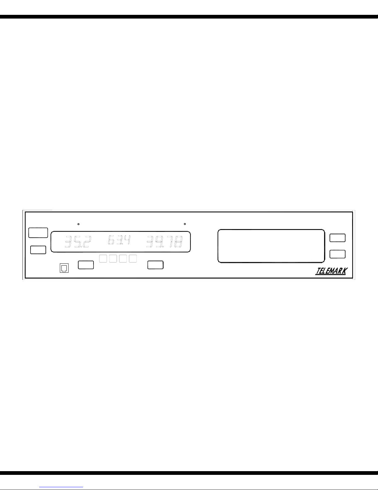
Model 880
Thin Film
Deposition Controller
STOP
START
RATE-A/SEC POWER-% THICKNESS-KA
MANUAL
CONTROL
MANUAL
ZERO
MODEL 880
DEPOSITION CONTROLLER
MENU
STATUS
Users Manual
June 7 2003,
518-030 Preliminary
p
Model 880 DEPOSITION CONTROLLER
TFC-2002 JM
USERS MANUAL 518-030
Rev <preliminary> June 7, 2003
.current:
Telemark Model 880 Deposition Controller
>
y
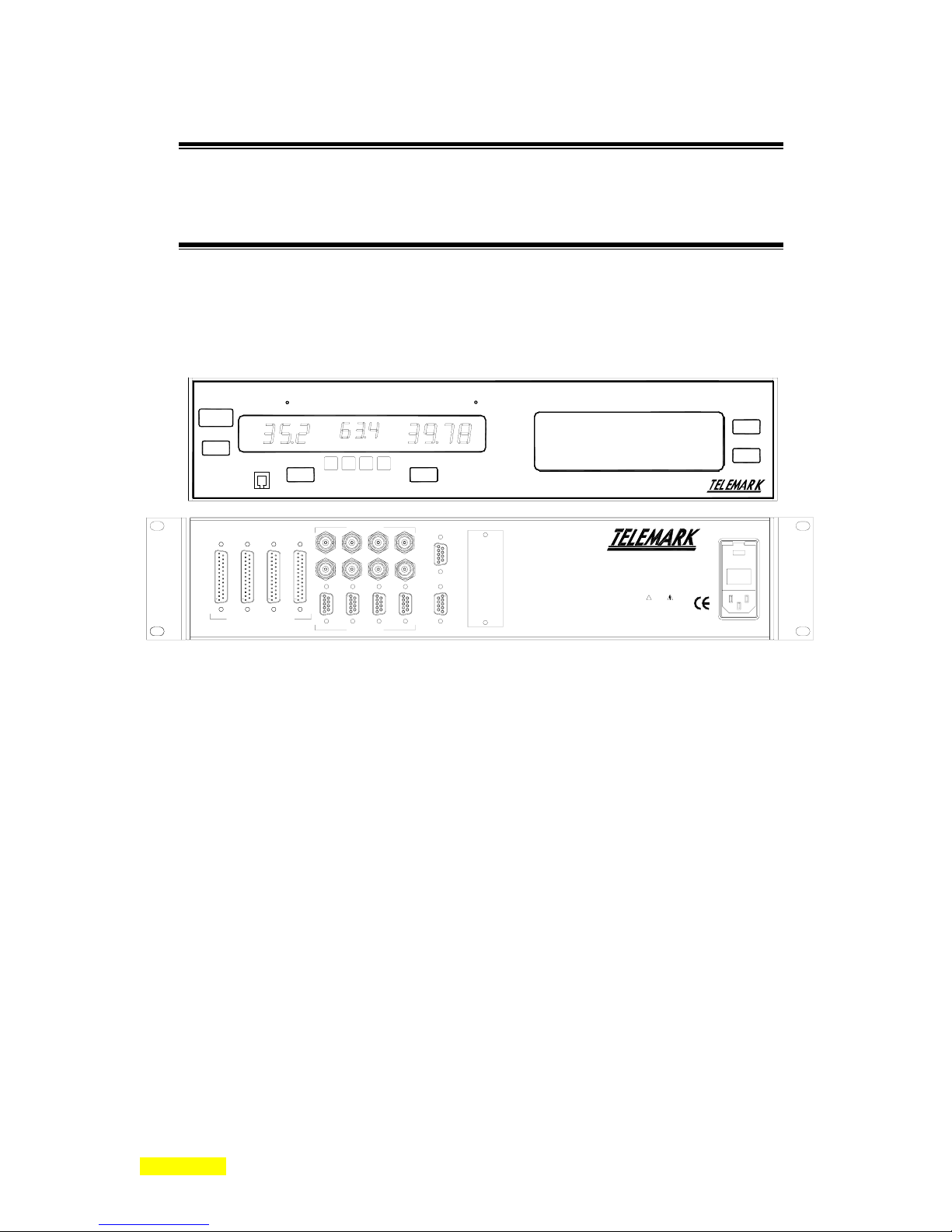
RATE-A/SEC POWER-% THICKNESS-KA
MANUAL
MANUAL ZERO
CONTROL
I/O 4 1/O 3 I/O 2 I/O 1
INPUTS / OUTPUTS
SENSORS
7 5 3 1
8 6 4 2
7 5 3 1
8 6 4 2
SOURCE
RS232
MEM
COMM OPTION
MODEL 880
DEPOSITION CONTROLLER
FUSE: 2 x 2.00 AMP
QUICK-ACTING (F) 250v
90-264 vac, 50-60 Hz, 230VA MAX
!
WARNING
The power cord protective
grounding conductor must be
connected to ground. No user
serviceable parts inside. Refer
servicing to qualified personnel.
>
STOP
START
.overview w/ generalizations only
intro to user interface, overview from general to specific
=
overview w/ generalizations and intro to specifics as generalizations are developed.
Telemark reserves the right to change any information contained in this manual without notice
<
©
Copyright Sycon Instruments, Inc. & Telemark 2003
®
AMPHENOL
®
is a registered trademark of Tyco/Amp, Inc.
AMP
ConFlat
®
Is a registered trademark of IBM Corporation
IBM
Microsoft
Microdot
SWAGELOK
Windows
is a registered trademark of Allied Corporation
®
is a registered trademark of Varian Associates, Inc.
®
is a registered trademark of Microsoft Corporation
®
®
®
is a registered trademark of Microdot Inc.
is a trademark owned by Crawford Fitting Company
is a registered trademark of Microsoft Corporation
.
MENU
STATUS
SECTION 0.XX
e page 1 of 275 ^

p
Model 880 DEPOSITION CONTROLLER
y
Warranty
The model 880 Deposition Controller is guaranteed against faulty materials, function, and workmanship for
a period of 12 months after delivery from Telemark. Components which are purchased by Telemark from
other manufactures will be guaranteed for any lesser time that such manufacturer warrants its product to
Telemark. This warranty is valid only for normal use where regular maintenance is performed as instructed.
This warranty shall not apply if repair has been performed or an alteration made by anyone other than an
authorized Telemark representative or if a malfunction occurs through abuse, misuse, negligence, or
accident. No charge will be made for repairs made under warranty at Telemark's facilities. Freight costs
both ways will be at customer's expense. Telemark reserves the right for final warranty adjustment.
.
User Responsibility
The user is responsible for proper operation an ordinary maintenance of the equipment, following
procedures described in this manual, including reference documents. Proper operation includes timely
replacement of parts that are missing, broken, or plainly worn. If the user has a reasonable doubt about
understanding the use or installation of a component, Telemark Technical Service should be called.
It is vitally important that the user properly install the equipment as described in the Installation sections of
this manual. The warranty will be void if the equipment is improperly installed.
Alteration of the design or any function of the equipment voids the warranty and is entirely the
responsibility of the user.
Safety Warning
General Precautions: Human contact with the voltages present within and around a vacuum system can be
fatal. Make sure that the input power is turned off before opening the doors or removing panels. Short all
HV feedthrough connections with a grounding hook before accessing the controller main body.
Disclosure
The disclosure of this information is to assist owners of Telemark equipment to properly operate and
maintain their equipment, and does not constitute the release of rights hereof. Reproduction of this
information and equipment described herein is prohibited without prior written consent from Telemark.
SECTION 0.XX
e page 2 of 275 ^

p
Model 880 DEPOSITION CONTROLLER
y
SECTION 1.0
.specifications/included materials
(no intro here) unpacking.
Introduction
Unpacking
The Model 880
interfaces and analog outputs (see the following spare parts included list). If the essential OSC-100A
oscillator or crystals were ordered at the same time, they will also be included. The unit operates from 90
to 264 VAC with no adjustments required. If it is ever necessary to return the unit to Telemark, for any
reason, call and obtain a Return Material Authorization number (RMA#).
comes with a power cord and connectors for the RS-232 interface, the I/O
Description
The Model 880 provides both automatic control of single or multi-layer film deposition in either a
production or development environment and improved predictability and repeatability of deposited film
characteristics through dependable digital control of the deposition process. It runs unattended in the fully
automatic mode and provides a wide number of benefits including performance limit access and setting by
the end user.
SECTION 1.1
.[please read and understand this manual before proceeding w/ equipment useage].
Please read and understand the contents of this manual before proceeding with equipment useage in a
working system. This manual will take the reader through the appropriate setup and example steps,
providing along the way, an understanding of how the Model 880 instrument is used. A test mode is
available from the SERVICE menu for simulated out of system experiments. Crystal sensor head
information is simulated (actually rate info is simulated for the film) allowing setup of various
parameters/programming elements without crystal failure halting the simulated process. The power supply
control voltage output is, however, active while in the test mode. All these terms will be described shortly.
This manual is organized into a number of main sections: specifications, generalized overview,
menu programming specifics and setup, hardware setup, detailed host communications, microbalance
theory and maintenance. If any further assistance is needed, please contact Telemark (see section 1.6).
The specifications section describes Model 880 product specifics, both hardware and software,
along with related necessary and optional product specifics. The software specifics include programmable
parameter lists. The generalized overview section answers the what, the how is it used and the how does it
work questions about the Model 880, that is, the solutions this product can provide. This section is intended
to discuss the concepts of main functions and elements with only enough detail to make the
conceptualization clear. In addition, rudimentary specifics are given in a number of other areas as an
introduction or a primer for the next section. This is information you typically only need to look at once.
Experienced users (those familiar with deposition controllers) should at least thumb through this section to
take an inventory of what is available. The menu programming specifics and operational details section
provides detailed information about product programming. Experienced users (those familiar with
deposition controllers) may decide to start here. If some elements are unclear, check back to the previous
section. The table of contents and index are helpful in this pursuit. This section provides descriptions for the
programming of film parameters and process steps, descriptions of menu navigation, descriptions of
screens, descriptions of fixed front panel keys, descriptions of run modes, parameter details, memory
defaults, programming summaries, etc. The hardware setup section describes and illustrates connectors,
interconnections, peripherals, mechanical connections, and the Model 880 as a component in a larger
system. Detailed host communications are found in the following section x6. See section x7 for
MANUAL DESCRIPTION
SECTION 1.XX
e page 3 of 275 ^
p
b
Model 880 DEPOSITION CONTROLLER
Microbalance theory and thickness reading calibration with its attendant density, z factor (a material
reference table of elements is included) and tooling determination. Each section builds on the previous
sections such that no new elements are used that haven't been defined.
.Some sage advice that is
seldom heeded.
.
If all else fails
read the manual.
You can lead a customer to water
ut you can't make them read the
manual.
y
SECTION 1.2 DESCRIPTION OF SYMBOLS
Please familiarize yourself with the following warning/safety/caution symbols found within this manual
and their general meaning:
Note
Caution
Static
Sensitive
.note the following warning/safety/caution symbols [desc. of each].
Note: Highlights an important fact or condition.
Caution: Warns of a condition that could cause damage to deposition controller, connected or
associated equipment. Also warns if some action taken could result with an undesireable and/or
unexpected outcome.
or
: Warns of a condition that will likely cause damage to the deposition controller, connected or
!
associated equipment. Also warns of a possible unsafe situation for the user. Examples are static
sensitivities, maximum component ratings, broken fuses, etc.
or
Hazardous
Voltages
Present
SECTION 1.XX
: Warns of a condition that is hazardous to user, deposition controller, connected or associated
equipment.
e page 4 of 275 ^

p
Model 880 DEPOSITION CONTROLLER
y
SECTION 1.3
TABLE OF CONTENTS
TITLE PAGE................................................................................................................................................ 1
WARRANTY................................................................................................................................................ 2
INTRODUCTION [1.XX] ............................................................................................................................ 3
S
ECTION
1.0 ................................................................................................................................................ 3
Unpacking Instructions........................................................................................................................... 3
ECTION
S
1.1 ................................................................................................................................................ 3
Manual Description: Usage, Organization, Section Contents Summary ............................................... 3
ECTION
S
1.2 ................................................................................................................................................ 4
Description of Symbols Found in Manual .............................................................................................. 4
ECTION
S
ECTION
S
1.3
TABLE OF CONTENTS
...................................................................................................... 5
1.4 .............................................................................................................................................. 11
STC-Spare Parts (included w/ Model 880)........................................................................................... 11
STC-Optional Parts .............................................................................................................................. 11
ECTION
S
1.5 .............................................................................................................................................. 11
STC-Optional Crystal Sensor Parts...................................................................................................... 11
ECTION
S
1.6 .............................................................................................................................................. 12
Contact Information ............................................................................................................................. 12
ECTION
S
1.7 .............................................................................................................................................. 13
Product Specifications.......................................................................................................................... 13
S
ECTION
1.8 ............................................................................................................................................. 14
Programmable Parameter Lists........................................................................................................... 14
Programmable Parameter Dependency Lists ..................................................................................... 17
ECTION
S
1.9 .............................................................................................................................................. 19
Sensor Specifications............................................................................................................................ 19
SIMPLE QUICK GENERALIZED OVERVIEW [2.XX]..................................................................... 21
ECTION
S
2.0 .............................................................................................................................................. 21
For What Is The Model 880 Used? [The Problem, The Solution]........................................................ 21
ECTION
S
2.1 .............................................................................................................................................. 22
How Is It Used?.................................................................................................................................... 22
ECTION
S
2.2 .............................................................................................................................................. 26
How Does It Work? .............................................................................................................................. 26
Hardware Setup Discussion ................................................................................................................. 29
Sensor Head: Hardware Generalizations............................................................................................. 30
Power Supply Connection .................................................................................................................... 32
Strip Chart Recorder Connection......................................................................................................... 32
RS-232 Communications Connection................................................................................................... 32
Grounding Stud .................................................................................................................................... 33
Input Card Options............................................................................................................................... 33
Installation/Removal Of Sensor Cards, Input Cards, Output Cards .................................................... 34
Pendant (hand controller) .................................................................................................................... 35
LCD Contrast/Bias ............................................................................................................................... 35
Graphical Display ................................................................................................................................ 35
Mounting .............................................................................................................................................. 35
System Hardware Connections............................................................................................................. 35
Programmable Hardware Setup Discussion ........................................................................................ 36
Select RunTime Mode: Sequencing/Non-Sequencing, Manual Mode, Test Mode............................................ 36
Memory Storage of Menu Parameters ............................................................................................................... 36
Films & Processes / Active, Non-Active ........................................................................................................... 36
Menu Parameter Dependencies.......................................................................................................................... 36
Tooling: Material Density & Z-Factor............................................................................................................... 37
SECTION 1.XX
e page 5 of 275 ^

p
Model 880 DEPOSITION CONTROLLER
Power Related Menu Parameters....................................................................................................................... 37
Power Related Menu Parameter Dependencies ................................................................................................. 38
y
Initial Programming Setups (menu parameters) .................................................................................. 40
Menu Parameter Values & Programming After Memory Purge........................................................................ 40
Menu Parameter Values & Programming After Factory Restored Memory ...................................................... 41
I/O Programming Introduction ............................................................................................................ 42
Boolean Logic Discussion ................................................................................................................................. 43
Simple I/O Program Examples .......................................................................................................................... 44
How To Develop I/O Programs............................................................................................................ 48
MENU PROGRAMMING AND OPERATION DETAILS [3.XX] ...................................................... 49
ECTION
S
3.0 .............................................................................................................................................. 49
LCD Touch Panel Overlay ................................................................................................................... 49
Front Panel Definitions ........................................................................................................................ 50
S
ECTION
3.1 .............................................................................................................................................. 56
Navigating Through Model 880 Menus................................................................................................ 56
Menu Tree............................................................................................................................................. 57
ECTION
S
3.2 .............................................................................................................................................. 58
RunTime Screen Description................................................................................................................ 58
ECTION
S
3.3 .............................................................................................................................................. 60
Main Menu Description........................................................................................................................ 60
ECTION
S
3.4 .............................................................................................................................................. 63
Films And Processes............................................................................................................................. 63
ECTION
S
3.5 .............................................................................................................................................. 63
Film Edit/Review Mode ........................................................................................................................ 63
Film Parameter Checksum................................................................................................................................. 67
Film Parameter Lock Code................................................................................................................................ 67
Film Parameter: Source Sensor Map Select....................................................................................................... 68
Review SS MAP................................................................................................................................................ 68
Selecting the Active Film in Non-Sequencing Mode......................................................................................... 69
Detailed Film Parameter Descriptions ................................................................................................ 71
Detailed Map Parameter Descriptions................................................................................................. 79
S
ECTION
3.6 ............................................................................................................................................. 83
Editing Processes................................................................................................................................. 83
Process Lock Code ............................................................................................................................................ 93
Factory Restoration vs. Purged Settings ............................................................................................................ 93
Changing Memory Settings ............................................................................................................................... 93
ECTION
S
3.7 .............................................................................................................................................. 93
Set Active Process................................................................................................................................. 93
ECTION
S
3.8 .............................................................................................................................................. 94
Non-Sequencing Differences ................................................................................................................ 94
ECTION
S
3.9 .............................................................................................................................................. 96
Software Controlled RunTime Screen Keys.......................................................................................... 96
L/Q key (Crystal Quality).................................................................................................................................. 96
SMPL key (Sample and Hold)........................................................................................................................... 96
ECTION
S
3.10 ............................................................................................................................................ 97
Manual Power Control......................................................................................................................... 97
Using Pendent.................................................................................................................................................... 97
Using LCD keys ................................................................................................................................................ 98
ECTION
S
3.11 ............................................................................................................................................ 99
Model 880 Shutter Delay...................................................................................................................... 99
ECTION
S
3.12 ............................................................................................................................................ 99
Deposition Source Control Loop Description ...................................................................................... 99
ECTION
S
3.13 .......................................................................................................................................... 101
Film Phases And Parameter Groups.................................................................................................. 101
ECTION
S
3.14 .......................................................................................................................................... 102
System Configuration ......................................................................................................................... 102
ECTION
S
3.15 .......................................................................................................................................... 103
SECTION 1.XX
e page 6 of 275 ^

p
Model 880 DEPOSITION CONTROLLER
y
Detailed System Configuration Related Parameters.......................................................................... 103
ECTION
S
3.16 .......................................................................................................................................... 105
Communications Configuration Related Parameters......................................................................... 105
Detailed Communications Configuration Related Parameters......................................................................... 106
ECTION
S
3.17 .......................................................................................................................................... 108
Model 880 Crystal Failure Processing............................................................................................... 108
ECTION
S
3.18 .......................................................................................................................................... 112
Process Accounting ............................................................................................................................ 112
ECTION
S
3.19 .......................................................................................................................................... 114
OPTions/INFo .................................................................................................................................... 114
Checksum Validation ........................................................................................................................ 115
Checksums And Parameters After Purge............................................................................................116
ECTION
S
3.20 .......................................................................................................................................... 118
Memory Module Programming & Usage........................................................................................... 118
Memory Module Data Transfer ....................................................................................................................... 120
Memory Module Placement............................................................................................................................. 121
ECTION
S
3.21 .......................................................................................................................................... 122
Programming Example....................................................................................................................... 122
Entering The TEST Mode................................................................................................................................ 122
ECTION
S
3.22 .......................................................................................................................................... 130
Product Programming Summary........................................................................................................ 130
ELECTRICAL CONNECTIONS AND DESCRIPTIONS [4.XX] ..................................................... 135
ECTION
S
4.0 ............................................................................................................................................ 135
Sensor Head Installation .................................................................................................................... 135
ECTION
S
4.1 ............................................................................................................................................ 138
Electrical Connections And Descriptions........................................................................................... 138
ECTION
S
4.2 ............................................................................................................................................ 138
Line Power ......................................................................................................................................... 138
ECTION
S
4.3 ............................................................................................................................................ 138
Rack Mounting.................................................................................................................................... 138
ECTION
S
4.4 ............................................................................................................................................ 138
Vacuum System Grounding ................................................................................................................ 138
ECTION
S
4.5 ............................................................................................................................................ 140
Sensor Connections ............................................................................................................................ 140
ECTION
S
4.6 ............................................................................................................................................ 140
Analog Control Voltage Connections................................................................................................. 140
Control Voltage Output Connection................................................................................................... 140
ECTION
S
4.7 ............................................................................................................................................ 141
Analog Recorder Output Connection ................................................................................................. 141
Analog Recorder Output Specifications ............................................................................................. 141
ECTION
S
4.8 ............................................................................................................................................ 143
I/O Interface ....................................................................................................................................... 143
ECTION
S
4.9 ............................................................................................................................................ 146
Relay Outputs (Factory I/O Program) ............................................................................................... 146
ECTION
S
4.10 .......................................................................................................................................... 147
Remote Inputs (Factory I/O Program) ............................................................................................... 147
ECTION
S
4.11 .......................................................................................................................................... 147
RS-232 Serial Communications Interface........................................................................................... 147
ECTION
S
4.12 .......................................................................................................................................... 148
Communications Options ................................................................................................................... 148
I/O PROGRAMMING [5.XX]................................................................................................................ 149
ECTION
S
5.1 ............................................................................................................................................ 149
I/O Programming Introduction .......................................................................................................... 149
ECTION
S
SECTION 1.XX
5.2 ............................................................................................................................................ 153
e page 7 of 275 ^

p
Model 880 DEPOSITION CONTROLLER
y
Boolean Definitions............................................................................................................................ 153
ECTION
S
5.3 ............................................................................................................................................ 154
States And Events ............................................................................................................................... 154
ECTION
S
5.4 ............................................................................................................................................ 159
Steady State vs. Edges ........................................................................................................................ 159
ECTION
S
5.5 ............................................................................................................................................ 159
Input Functions................................................................................................................................... 159
ECTION
S
5.6 ............................................................................................................................................ 160
Output Functions................................................................................................................................ 160
ECTION
S
5.7 ............................................................................................................................................ 160
Softnodes And Sync Events................................................................................................................. 160
ECTION
S
5.8 ............................................................................................................................................ 161
Internal Operations ............................................................................................................................ 161
ECTION
S
5.9 ............................................................................................................................................ 162
Operate Menu..................................................................................................................................... 162
ECTION
S
5.10 .......................................................................................................................................... 162
Memory Menu..................................................................................................................................... 162
ECTION
S
5.11 .......................................................................................................................................... 163
Editing An I/O Program ..................................................................................................................... 163
I/O Programming Tree....................................................................................................................... 165
ECTION
S
5.12 .......................................................................................................................................... 168
I/O Setup Edit Menu ........................................................................................................................... 168
ECTION
S
5.13 .......................................................................................................................................... 169
Edit/Change Menu.............................................................................................................................. 169
COMPUTER INTERFACING [6.XX].................................................................................................. 191
ECTION
S
6.0 ............................................................................................................................................ 191
Host Port Interface............................................................................................................................. 191
THEORY AND CALIBRATION [7.XX] .............................................................................................. 261
ECTION
S
EASUREMENT THEORY
7.0 M
.................................................................................................... 261
Equation 1 .......................................................................................................................................... 261
ECTION
S
7.1 C
ALIBRATION
..................................................................................................................... 262
Thickness ............................................................................................................................................ 262
Density Determination....................................................................................................................... 262
Z-Factor Determination ..................................................................................................................... 262
Tooling Dtermination ......................................................................................................................... 262
Material Reference Table:.................................................................................................................. 264
Aluminum Through Indium............................................................................................................................. 264
Indium Intimonide Through Terium................................................................................................................ 265
Thallium Through Zirconium Oxide................................................................................................................ 266
MAINTENANCE/PROBLEM SOLUTIONS [8.XX]........................................................................... 267
ECTION
S
8.0 ............................................................................................................................................ 267
Warnings/Cautions ............................................................................................................................. 267
User Correctable System Problems.................................................................................................... 267
ECTION
S
8.1 R
EPLACING
ENSOR CRYSTAL
A S
....................................................................................... 268
Cautions/Procedural Steps................................................................................................................. 268
ECTION
S
8.2
PERSISTENT CRYSTAL FAIL INDICATION
........................................................................ 268
Discussion .......................................................................................................................................... 268
Hardware Issues ................................................................................................................................. 269
ECTION
S
ECTION
S
8.3
8.4
SYSTEM BATTERY AND MEMORY CONSIDERATIONS
................................................................................................................................270
S
FAQ
..................................................... 270
Procedure to Change Battery ............................................................................................................. 270
GLOSSARY .............................................................................................................................................. 271
SECTION 1.XX
e page 8 of 275 ^

p
Model 880 DEPOSITION CONTROLLER
INDEX....................................................................................................................................................... 273
COPY PARAMETER LISTS.................................................................................................................. 274
y
FIGURES
Standard Sensors.................................................................................................................................. 20
Sequencing / Non-Sequencing Modes................................................................................................... 23
Process / Film / Map Relationships...................................................................................................... 25
Back Panel Connections (Overview).................................................................................................... 29
Electrical Connections From Crystal Through Remote Oscillator (Overview) ................................... 30
Input Bd. Jumpers (Overview).............................................................................................................. 33
Installation/Removal Of Back Panel PCB Cards ................................................................................. 35
I/O Programming Notation .................................................................................................................. 44
I/O Programming Description.............................................................................................................. 44
I/O Programming: User Programmable Front Panel Keys/LEDs....................................................... 45
Example I/O Programs......................................................................................................................... 45
I/O Programming: Modulo 100 Counter Addresses............................................................................. 47
Touch Panel Overlay............................................................................................................................ 49
Front Panel and Key Descriptions ....................................................................................................... 50
Typical RunTime Screen....................................................................................................................... 50
Status Key Screens................................................................................................................................ 51
Manual Mode Screens .......................................................................................................................... 52
Status Screen Selector Function ........................................................................................................... 54
Start Key Menu..................................................................................................................................... 54
Start (Key) Process Flowchart ............................................................................................................. 55
Menu Tree............................................................................................................................................. 57
RunTime Screen.................................................................................................................................... 58
Main Menu Screen................................................................................................................................ 60
Executive Menu .................................................................................................................................... 62
Films & Process Storage...................................................................................................................... 63
Review Film Menu................................................................................................................................ 64
Non-Sequencing Mode Screen.............................................................................................................. 69
Rate Sampling, Sample And Hold Operation ....................................................................................... 75
Main Process Review/Edit Screen........................................................................................................ 83
Service Menu, Memory Configurations................................................................................................ 93
Setting the Active Process (Sequencing Mode)..................................................................................... 94
Setting The Active Film (Non-Sequencing Mode.................................................................................. 94
RunTime Screen (Non-Sequencing Mode)............................................................................................ 95
RunTime Screen: L/Q ........................................................................................................................... 96
RunTime Screen: Sample & Hold......................................................................................................... 96
Hand Controller/Pendent ..................................................................................................................... 97
Manual Power Control......................................................................................................................... 98
Typical Run Cycle............................................................................................................................... 101
System Configuration Screens............................................................................................................ 102
Communications Menu Screen ........................................................................................................... 105
Process Accounting Screens............................................................................................................... 112
Options Info Screens........................................................................................................................... 114
Memory Module.................................................................................................................................. 118
RunTime Screen With Test Mode Enabled ......................................................................................... 122
Electrical Connections To Back Panel............................................................................................... 135
Crystal Head Mounting ...................................................................................................................... 135
Rear Panel.......................................................................................................................................... 138
Recommended System Grounding ...................................................................................................... 139
SECTION 1.XX
e page 9 of 275 ^

p
Model 880 DEPOSITION CONTROLLER
y
Rate Mode Recorder Output............................................................................................................... 142
I/O: Input Configuration Jumpers...................................................................................................... 143
I/O: Input Configuration Jumpers...................................................................................................... 145
RS232 Interface Cable........................................................................................................................ 148
I/O Programming Menu Screen.......................................................................................................... 149
Relay Ladder Notation........................................................................................................................ 153
Stack I/O Operations .......................................................................................................................... 161
I/O Programming Menu Screen Descriptions .................................................................................... 163
I/O Programming Menu Tree............................................................................................................. 165
I/O Programming Menu Descriptions................................................................................................ 166
I/O Programming Edit Menu Description.......................................................................................... 168
I/O Programming EDT/CHG Screens 1-5.......................................................................................... 171
I/O Programming: I/O program Entry ............................................................................................... 174
I/O Programming: Inserting An Empty Rung..................................................................................... 179
I/O Programming: Changing the Rung ..............................................................................................179
I/O Usage of Hand Controller/Pendent.............................................................................................. 188
Making An RS232 Cable..................................................................................................................... 191
Communications Setup Mode ............................................................................................................. 193
Equation 1 .......................................................................................................................................... 261
Density Calculation............................................................................................................................ 262
Z-Factor Calculation.......................................................................................................................... 262
Typical Tooling Factors ..................................................................................................................... 263
Sensor Feedthrough Connections....................................................................................................... 269
TABLES
ACTORY SETTINGS
F
OOLEAN LOGIC
B
ACTORY SETTINGS
F
HASES AND PARAMETERS
P
HECKSUMS AFTER PURGED
C
RODUCT PROGRAMMING SUMMARY TABLES
P
ACTORY RELAY OUTPUT PROGRAM
F
RUTH TABLE
T
VENT AND STATE
E
VENT AND STATE
E
ACTORY INSTALLED
F
ODULO
M
IXED DELAY
F
ESPONSE CHARACTER TABLE
R
ATERIAL REFERENCE TABLE
M
......................................................................................................................................... 154
OUNTER PROGRAM
6 C
& P
ROCESS PROGRAMS
, P
............................................................................................... 41
....................................................................................................................................... 43
ROCESS PROGRAMS
, P
............................................................................................... 93
..................................................................................................................... 101
FTER FACTORY RESTORED MEMORY
/ A
................................................... 116
........................................................................................ 130
...................................................................................................... 146
IST
ID L
ID L
.................................................................................................................... 155
IST
.................................................................................................................... 158
ROGRAM
I/O P
....................................................................................................... 181
............................................................................................................. 185
ULSE WIDTH
I/O P
ROGRAM
........................................................................................ 186
............................................................................................................... 194
................................................................................................................ 264
SECTION 1.XX
e page 10 of 275 ^

SECTION 1.4
.included parts: STC-2002, power cord, spare parts.
p
Model 880 DEPOSITION CONTROLLER
y
Model 880 Spare Parts
POWER CORD [120 VAC] (1) 600-004
FUSES (2 x 2.00A 250VAC F-type) 356-014
OPTOCOUPLED INPUTS 25 PIN MALE CONNECTOR (1) 402-222
RELAY OUTPUTS 25 PIN FEMALE CONNECTOR (1) 404-020
EMI HOOD FOR 25 PIN CONNECTORS (2)..........................404-021
RS-232 9 PIN MALE CONNECTOR (1)..................................404-011
EMI HOOD FOR 9 PIN CONNECTOR (1)..............................404-009
RACK MOUNT EARS (2) ........................................................016-012
RACK MOUNT HDWR (4) ......................................................094-006
MANUAL (this manual)............................................................518-029
CONNECTOR KIT / PARTS ....................................................516-017
HAND CONTROLLER (1) .......................................................500-198
COMMUNICATIONS SOFTWARE TOOLS DISK (1)...........500-046
ASSEMBLY PART NUMBER
(included with Model 880)
Optional Model 880 Hardware / Software
MEMORY MODULE/STRIP CHART INTERFACE PCB 500-212
TRANSPORTABLE MEMORY MODULE (32K) ..................500-210
TRANSP. MEMORY MODULE SOFTWARE FOR PC..........500-TBD
TRANSP. MEMORY MODULE CABLE FOR PC..................500-TBD
SECTION 1.5
Optional Sensor Parts
Description................................................................. Telemark Part Number
Sensor Body (Low Profile) .......................................................550-222
Sensor Cap (Low Profile)...........................................................550-223
30 inch In-Vacuum Coax Cable ................................................500-024
10 inch In-Vacuum Coax Cable ................................................500-023
Crystals (box of 10) ...................................................................500-117
Standard Feedthroughs
1" BOLT STANDARD .............................................................500-016
2 3/4" ConFlat STANDARD ....................................................500-017
Standard Sensors
LOW PROFILE .........................................................................500-042
RIGHT ANGLE.........................................................................500-088
SECTION 1.XX
e page 11 of 275 ^

Model 880 DEPOSITION CONTROLLER
Cables
10' OSC TO CONTROL UNIT CABLE ...................................500-026
30' OSC TO CONTROL UNIT CABLE ...................................500-027
6" OSC TO FEEDTHROUGH COAX CABLE ........................500-025
Crystal / Oscillator Package
6" OSC TO FEEDTHROUGH COAX CABLE ........................500-025
10' OSC TO CONTROL UNIT CABLE ...................................500-026
OSCILLATOR UNIT ...............................................................OSC-100A
10 CRYSTALS ..........................................................................500-117
(includes the following 4 item numbers)
SECTION 1.6 Contact Information
Model 880
Model 880 DEPOSITION RATE CONTROLLER
Sensor Package and Feedthrough Not Included
500-109
Website www.telemark.com
SECTION 1.XX
page 12 of 275

p
Model 880 DEPOSITION CONTROLLER
y
SECTION 1.7 PRODUCT SPECIFICATIONS
Model 880 Thin-Film Thickness and Rate Controller Specifications
High Resolution ±0.02Hz(5-6MHz), 0.0088 Angstroms/Measurement (for Aluminum)
High Accuracy ±0.5% thickness + 1 count
High Speed Ten measurements/second
Measurement Range 500KA Aluminum Equivalent
Standard Sensor Crystal 6 MHz AT cut, Plano/Convex
Sensor Capacity 2 per sensor PCB card [4 PCB cards max.]
Displays 240 x 64 pixel monochrome LCD with Backlight
12 digit LED display (7 segments each digit)
4 discrete indicator LEDs
Operation Menu driven "Windowing Type"
LCD Touch Panel (12 x 4 key matrix)
with 6 fixed function membrane keys
and 4 user programmable fixed membrane keys
Film Storage (Standard) 1 Active Film Program
98 Alternate Film Programs (with 30 Sensor maps)
9 Sequence recipes, 99 steps per recipe, system total is 250 steps
External Storage (Optional) Film Parameters for films 1-99 and System Parameters I/O programs,
and Process Accounting Can be stored in Transportable Data Module
(Optional)
Hardware I/O (Standard) per card: 8 SPDT Relays, 1.0 Amp @ 24 VDC Maximum
per card: 8 Optocoupled Inputs (Electrically Isolated), 5-24VDC [4
slots for input and/or output cards]
Computer Interface RS-232C (Sycon Format or ASCII)
Protocols
Communication Options DeviceNet, PROFIBUS, CANopen, others
Analog Outputs: 12 bit resolution (2 per sensor card, each for use as control or recorder)
As Control Outputs 2.5, 5, 10 volt @10ma. isolated output with range
menu programmable (maximum 2 control outputs per sensor card)
As Recorder Outputs 0 to 10 volt @ 10ma, isolated, function programmable
(rate, thickness, power, deviation, computer remote) (maximum 1
recorder output per sensor card and per system)
Power Control:
Automatic Three Mode Closed Loop Control (PID)
Manual Hand Controller
Rack Mount full width rack mount (std.). 3
Power Requirements 90-264VAC, 50-60Hz (
1.4A rms@120VAC, 0.7A rms@230VAC)
Weight (without options) 6 lbs. [with: 1 Sensor card, 1 Input Card, 1 Output Card]
card=0.216 lbs., Input card=0.135 lbs., Output card=0.14 lbs.
Operating Range 0 to 50°C ambient (power supply/LCD display)
Humidity non-condensing: 5% - 85% RH
1/2
" H, 8
5/8
" D
Sensor
SECTION 1.XX
e page 13 of 275 ^

p
Model 880 DEPOSITION CONTROLLER
y
SECTION 1.8
.programmable parameter list (1.4).
__________________________________________________________________
key examples:
Full Parameter Name
Parameter Name ⇒ Param N
(text) ⇒ implied parameter text in parenthesis
__________________________________________________________________
Film Parameter List:
Review Film (Edit Film)
(Material) Density 0.40 to 99.99 gm/cc
(Material) Z-Factor 0.100 to 9.999
Setpoint Thickness Limit 0.000 to 999.999 KÅ
Final Thickness Limit (Trigger) 0.000 to 999.999 KÅ (non-sequencing only)
Setpoint Time Limit 0:00 to 99:59 MM:SS
Soak 1 Power level Value 0.0 to 100.0%
Power Ramp 1 Time (to pwr level) 0 to 99:59 MM:SS
Power Soak 1 Time (@ pwr level) 0 to 99:59 MM:SS
Soak 2 Power level Value 0.0 to 100.0%
Power Ramp 2 Time (to pwr level) 0 to 99:59 MM:SS
Power Soak 2 Time (@ pwr level) 0 to 99:59 MM:SS
Soak 3 Power level Value 0.0 to 100.0%
Power Ramp 3 Time (to pwr level) 0 to 99:59 MM:SS
Deposit Rate (requested) 0.0 to 999.9 A/S
Rate Ramp Mode OFF / ON
New Deposit Rate (Value) 0.0 to 999.9 A/S
Rate Ramp Time (Duration) 0:00 to 99:59 MM:SS
Rate Ramp (Thickn) Trigger Point 0 to 999.999 KÅ
Control Loop –Proportional term- 1 to 9999
Control Loop –Integral term- 0.0 to 99.9 sec
Control Loop –Derivative term- 0.0 to 99.9 sec
Max Power Limit 0.0 to 100.0%
Abort Max Power SWitch OFF/ON
Max Power Dwell 0:01-99:59 MM:SS
Shutter Delay Mode OFF, ON
Shutter Delay TIMEOUT 0:01-99:59 MM:SS
Shutter Delay QUALITY 1-50%
(XTAL) RATE SAMPLING OFF,TIMED,INTELL.
(XTAL) SAMPLE INTERVAL 0:01-99:59 MM:SS
(XTAL) SAMPLE DWELL TIME 0:01-99:59 MM:SS
(XTAL) SAMPLE QUAL 1-50%
(XTAL) SAMPLE ALARM TIME 0:01-99:59 MM:SS
FILM Fail Mode ABORT IF FAIL, TIME POWER
Control Loop Qual Limits 0 to 9
XTAL Stability S (Limits) 0 to 9
XTAL Life Bounds 0.0-100.0%
Plot Vert Scale Volts 1, 5, 10, 50, 100
Plot Horiz Scale H 1 to 600 samples
Data Plot Type Rate /Rate Deviation /Power
Programmable Parameter Lists
⇒ Abbreviated Menu Name
[Menu end point: Review Film Menu path: Main/Review Film]
SECTION 1.XX
e page 14 of 275 ^

p
Model 880 DEPOSITION CONTROLLER
y
Source Sensor MAP SELECT 1 - 30
POCKET SELECT 0 – 63 Pockets
ETCHING MODE OFF/ON
Process Step elements:
Review Processes (Edit Process) (Edit Process Steps [1-99]) Mode (Skip, Stop, Auto,
[Menu end point: Review Processes Menu path: Main/Review Processes]
End, Wait), Film# (1-99), Thickness (0.0 - 999.999 KÅ)
Main Menu values:
[Menu end point: Main Menu Menu path: fixed front panel MENU key/ Main Menu]
Next Active Process (Select)* 1 of 9 processes [sequencing mode only]
Next Active Film (Select)* 1 of 99 films [non-sequencing mode only]
[*NOTE: press touch key enclosing digit to select 1 of the 9 processes or 99 films (press digits + ENTer on invoked submenu)]
RunTime Screen parameters:
[Menu end point: RunTime screen Menu path: programming Menu/ fixed front panel STATUS key/RunTime screen]
(Crystal Quality Indicator Select) L/Q, Loop x, Qual xx
(Crystal Sample Select) (not selected [blank]), SMPL, SMPL+Time, HOLD+Time
START key sequence
STOP key
MANUAL key
ZERO key
MENU key
STATUS key
(fixed front panel)
(fixed front panel)
(fixed front panel)
(fixed front panel)
(fixed front panel)
(fixed front panel)
Zeroes the thickness value
Switches from RunTime screen to MAIN menu screen
PROCess X:
(Note
Stops the running process
message change after each START process key press)
(non-seq mode: stops the 1 inherent process [film])
Switches to manual mode from a running process only. Toggle action.
Switches to RunTime screen from any menu screen, to detailed power
and crystal info screens from RunTime screen
Zero Power
Zero Thickness
Force Fail
1
Zero thickness does not affect film thickness value, only Source Sensor card value (use to set tooling factor, diagnose
problems, etc. )
2
If the PROCess X: status message does not change when the START key is pressed, check for "STOP: INValid XXX "
message or check the OPT/INF menu, page 2 for cards not installed which are enabled in software (MIA). Cycle AC power
OFFON to re-sync.
System Configuration values:
[non-active process]
1
zero channel 1-8, zero all, re-verify
[non-active process]
zero channel 1-8, zero all [1st STATUS key press from RunTime]
fail channel 1-8, fail all, re-verify
[Menu end point: System Config Menu path: Main/Executive menu/System Configuration]
[2nd STATUS key press from RunTime]
[2nd STATUS key press from RunTime]
LCD Contrast / Bias LOW, MEDIUM, HIGH
Password Lock # 0 - 9999
(Process) Run Number 0 to 9999
Recorder Function
Recorder Out Channel
Absolute Rate, Rate Deviation, Power, Thickness, Computer Remote, I/O Control, Off
1 – 8 selects an analog output channel for use (if not off and not used as a source)
Real Clock Time HH/MM
Real Clock Date MM/DD/YY
Need Source/Sensor Card 1 OFF/ON
Need Source/Sensor Card 2 OFF/ON
Need Source/Sensor Card 3 OFF/ON
Need Source/Sensor Card 4 OFF/ON
I/O Slot 1 Type UNUSED (DISABLED) / INPUT / OUTPUT
I/O Slot 2 Type UNUSED (DISABLED) / INPUT / OUTPUT
I/O Slot 3 Type UNUSED (DISABLED) / INPUT / OUTPUT
I/O Slot 4 Type UNUSED (DISABLED) / INPUT / OUTPUT
Memory Module IFC OFF/ON
Communication values:
[Menu end point: Comm. Setup Menu path: Main/Executive menu/Communications Setup]
COM/IO Lock Code 0 - 9999
Keyboard Beep OFF / ON
RS232 Baud Rate 300, 1200, 2400, 9600
RS232 Protocol Sycon, ASCII
2
SECTION 1.XX
e page 15 of 275 ^

p
Model 880 DEPOSITION CONTROLLER
y
Source Sensor Map elements:
[Menu end point: Review SS Map Menu path: Main/Review SS Map]
Source Sensor Full Power Volts 2.5, 5, 10 full scale volts
Source Sensor Max Power Value 0.0% - 100.0%
Source Sensor Analog Output Chnl 1 – 8 Channel Selection
Master Tooling Value 10.0% - 400.0%
Minimum Start Xtal Channels 1 – 8 minimum channels
Minimum Backup Xtal Channels 0 – 7 minimum channels
Minumum Active Xtal Channels 1 – 8 minimum channels
(Xtal) Channel Drop Filter NONE, BALANCE
[Mask dropped Xtal channel Failure]
averaging mode only
Indexer Synchronization Mode NONE, DELAY, FEEDBACK
Indexer Synchronization Time 2 – 999 seconds
Channel 1 Start Mode OFF, ACTIVE, STANDBY
Channel 1 Fail Action (Mode) NONE, ABORT FILM
Channel 1 Backup List X – XXXXXXXX (1 item list to 8 item list), [where X = 1 to 8 (in
each position w/o redundancies, list extends to 0-8 for a 1 item list)]
Channel 1 Tooling Value 10.0% - 400.0%
Channel 1 Weight 10.0% - 400.0%
Channel 2 Start Mode OFF, ACTIVE, STANDBY
Channel 2 Fail Action (Mode) NONE, ABORT FILM
Channel 2 Backup List X – XXXXXXXX,
[X = 1 to 8 (in each position w/o redundancies)] see CH1
Channel 2 Tooling Value 10.0% - 400.0%
Channel 2 Weight 10.0% - 400.0%
Channel 3 Start Mode OFF, ACTIVE, STANDBY
[need 2nd Source Sensor Card for Channels 3 & 4]
Channel 3 Fail Action (Mode) NONE, ABORT FILM
Channel 3 Backup List X – XXXXXXXX,
[X = 1 to 8 (in each position w/o redundancies)] see CH1
Channel 3 Tooling Value 10.0% - 400.0%
Channel 3 Weight 10.0% - 400.0%
Channel 4 Start Mode OFF, ACTIVE, STANDBY
Channel 4 Fail Action (Mode) NONE, ABORT FILM
Channel 4 Backup List X – XXXXXXXX,
[X = 1 to 8 (in each position w/o redundancies)] see CH1
Channel 4 Tooling Value 10.0% - 400.0%
Channel 4 Weight 10.0% - 400.0%
Channel 5 Start Mode OFF, ACTIVE, STANDBY
[need 3rd Source Sensor Card for Channels 5 & 6]
Channel 5 Fail Action (Mode) NONE, ABORT FILM
Channel 5 Backup List X – XXXXXXXX,
[X = 1 to 8 (in each position w/o redundancies)] see CH1
Channel 5 Tooling Value 10.0% - 400.0%
Channel 5 Weight 10.0% - 400.0%
Channel 6 Start Mode OFF, ACTIVE, STANDBY
Channel 6 Fail Action (Mode) NONE, ABORT FILM
Channel 6 Backup List X – XXXXXXXX,
[X = 1 to 8 (in each position w/o redundancies)] see CH1
Channel 6 Tooling Value 10.0% - 400.0%
Channel 6 Weight 10.0% - 400.0%
Channel 7 Start Mode OFF, ACTIVE, STANDBY
[need 4th Source Sensor Card for Channels 7 & 8]
Channel 7 Fail Action (Mode) NONE, ABORT FILM
Channel 7 Backup List X – XXXXXXXX,
[X = 1 to 8 (in each position w/o redundancies)] see CH1
Channel 7 Tooling Value 10.0% - 400.0%
Channel 7 Weight 10.0% - 400.0%
Channel 8 Start Mode OFF, ACTIVE, STANDBY
Channel 8 Fail Action (Mode) NONE, ABORT FILM
Channel 8 Backup List X – XXXXXXXX,
[X = 1 to 8 (in each position w/o redundancies)] see CH1
Channel 8 Tooling Value 10.0% - 400.0%
Channel 8 Weight 10.0% - 400.0%
SECTION 1.XX
e page 16 of 275 ^

p
Model 880 DEPOSITION CONTROLLER
y
I/O Function elements:
I/O Relay Functions user I/O program
[Menu end point: I/O Setup Menu path: Main/Executive menu/ I/O Setup]
(8 Form C Relays per card [4 slots available for I or O cards])
I/O Input Functions user I/O program + PCB jumpers
(8 Inputs per card [4 slots for I or O cards])
I/O Setup Memory: save/swap, Operate: run/stop
I/O Programming Edit (Program): IN, NOT, AND, OR, XOR, POSitive, NEGative,
OUT, TRiP, SET, CLeaR, ARM, DRoP, (events/states/logical
operators), (softnodes) and (numeric elements).
Arithmetic operators/elements: KON# (to input constants), ADD,
SUBtract, MULtiply, DIVide, MODulus, EQUals, GReaTer than,
LESs than, and SELect. Editing: backspace, left/right arrows (to move
cursor), delete, undo, insert/delete line.
(Front Panel LEDs [4 discrete]) I/O programming elements (see table x in section 5xx and Section 2.2)
(User Front Panel Keys [4]) I/O programming elements (see table x in section 5xx and Section 2.2)
Pendent Keys (beyond specified Manual Mode use: I/O programming elements
[see table xxx in section 5xx ])
Service Menu values:
[Menu end point: Service Menu path: Main/Service]
(Test Mode Select) Test Off, Test On [Test Mode won't remain in effect if power is cycled)
(Seq/Non-seq Mode Select) Seq(uencing Mode Select en)able, Non-seq(uencing Select enabled)
(Memory Contents) as is (no modification), purged, factory (defaults) [see section x.2.2xx ]
(Reset) Arm reset, reset armed [Provide a product reset when back panel power
switch is not accessible. Also, use to generate ACCEPT key if not
present (e.g. to end the Test mode when in the Test mode).]
<<< move the following depenency lists to end of section 2.22? >>>
[Prerequisite states that must be in effect for the following parameters to be fully functional]
Film Parameter Dependency List:
Material Density Not Applicable
Material Z-Factor N.A.
Setpoint Thickness Limit N.A.
Final Thickness Limit (Trigger) Service Menu Parameter: Non Seq / Accept (Bug: 2
Setpoint Time Limit N.A.
Soak 1 Power level Value N.A.
Power Ramp 1 Time (to pwr level) N.A.
Power Soak 1 Time (@ pwr level) N.A.
Soak 2 Power level Value N.A.
Power Ramp 2 Time (to pwr level) N.A.
Power Soak 2 Time (@ pwr level) N.A.
Soak 3 Power level Value N.A.
Power Ramp 3 Time (to pwr level) N.A.
Deposit Rate (requested) N.A.
Rate Ramp Mode N.A.
New Deposit Rate Value Film Parameter: Rate Ramp Mode = ON
Rate Ramp Time Duration Film Parameter: Rate Ramp Mode = ON
Rate Ramp (Thickn) Trigger Point Film Parameter: Rate Ramp Mode = ON
Control Loop –Proportional term- N.A.
Control Loop –Integral term- N.A.
Control Loop –Derivative term- N.A.
Max Power Limit N.A.
Abort Max Power SW N.A.
Max Power Dwell Film Parameter: Abort Max Power SW = ON
nd
µP not reset)
SECTION 1.XX
e page 17 of 275 ^

p
Model 880 DEPOSITION CONTROLLER
y
Shutter Delay Mode N.A.
Shutter Delay TIMEOUT Film Parameter: Shutter Delay Mode = ON
Shutter Delay QUALITY Film Parameter: Shutter Delay Mode = ON
(XTAL) RATE SAMPLING N.A.
(XTAL) SAMPLE INTERVAL (Film Parameter: (XTAL) RATE SAMPLING = Timed
or
Film Parameter: (XTAL) RATE SAMPLING = Inteli)
(XTAL) SAMPLE DWELL TIME Film Parameter: (XTAL) RATE SAMPLING = Timed
(XTAL) SAMPLE QUAL Film Parameter: (XTAL) RATE SAMPLING = Inteli
(XTAL) SAMPLE ALARM TIME Film Parameter: (XTAL) RATE SAMPLING = Inteli
FILM Fail Mode N.A.
Control Loop Qual Limits N.A.
XTAL Stability S Limits N.A.
XTAL Life Bounds N.A.
Plot Vert Scale Volts N.A.
Plot Horiz Scale H N.A.
Data Plot Type N.A.
Source Sensor MAP SELECT N.A.
POCKET SELECT N.A.
ETCHING MODE N.A.
Main Menu value Dependency List:
Next Active Process (Select)
If N/A, must use START + Reset / Start Proc keys to start a process.
Next Active Film (Select)
1
Service Menu: Sequence Able + Accept keys (for Sequencing Mode)2
1
Service Menu: Non-Sequence + Accept keys (Non-Sequencing Mode)2
Review Process (Select) Service Menu: Sequence Able + Accept keys (for Sequencing Mode)
Review Film (Select) N.A.
Review Source/Sensor Map (Sel)
[NOTE1: press to invoke number entry submenu, sequence of 1 or 2 digits is entered or discarded]
N.A.
Note2: [the Seq Able / Non Seq key shows the current mode upon entry into the
Service menu, changing the mode toggles key text and generates the Accept
key that in turn needs to be pressed to accept new mode described on the key
in text]
RunTime Screen parameter Dependency List:
(Crystal Quality Indicator Select) L/Q, Loop x, Qual xx Film Parameters
(Crystal Sample Select) Film Parameter: (XTAL) Rate Sampling = Timed or Intelligent?
Running in deposit mode
(Crystal Select) System Config Parameter: Need Source/Sensor Card X
Review Source Sensor Map Element Parameters:
Minimum Start Xtal Channels
Minumum Active Xtal Channels
Channel X Start Mode
(Process X) Main Menu Parameter: [Next Process] Digit
Fixed Front Panel START key: sequence from N/A to 1
Service Menu: SEQuence enABLE
Layer X (layer = step) Review Processes X: EDIT: CHANGE, INSERT, DELETE
Service Menu: SEQuence enABLE
FILM Review Processes X: EDIT: CHANGE, INSERT, DELETE films
Review Film X:
[non-sequencing mode]
(Manual mode) Running Process + Pressing fixed front panel MANUAL key +
attached Pendent
[sequencing mode]
[sequencing mode]
Layers/steps
[sequencing mode]
2
SECTION 1.XX
e page 18 of 275 ^

p
Model 880 DEPOSITION CONTROLLER
y
MAP# Film Parameter: Review Source/Sensor Map Select
SRC x Review Source/Sensor Map Parameter: Source Analog Output Channel
Film Parameter: Source/Sensor Map Select (select the map that
contains the above selected Source Analog Output Channel)
NOTE: If SRC is zero, this is an indication that a source analog output control voltage
has been assigned to a source sensor card that is not present, not working, etc.
Remember that the System Configuration parameters: Need Source/Sensor Card X and
I/O Slot X type are only evaluated on power up or on reset. Check the OPTions/INFo
menu, page 2 and 3 to see what is currently in effect. To work correctly, the S/S x: line
should end with OK. If it ends with EMPTY, the card is not present or not
communicating. If the line ends with INCOMPATable!, the software versions in at least
some of the various PCB cards is not compatible- check for field changed PCB cards. If
the line ends with MIA, that sensor card is configured but is not present. [See
OPTions/INFo menu]
RUN, PHASE automatic up/down timers. Function when process/film is started
(START key sequence). Effected by film parameters that control film
phases within the deposition cycle.
RUN x System Configuration Parameter: Run Number
TIME/Day of Week/DATE System Configuration Parameters: Clock Time, Clock Date
Graph Film Parameters: Plot Vert Scale Volts, Plot Horiz Scale H,
Data Plot Type
(process start) Carry out the following 2 key sequence up to 3 times.
Press the fixed front panel START key + 1 of 4 touch panel keys:
Break Wait, Next Layer, Restart Layer, Reset / Start Process
(see figure in end of section 3.0). Use the appropriate touch key for the
task at hand. If unsure, use Reset / Start Process key in all 3 sequences.
Please read and understand this manual before starting a live process.
(Test mode) [to enter] Service Menu: Test Off ⇒ Test On (text toggles) + Accept
(Test mode) [to exit] Service Menu: Arm Reset ⇒ Reset Armed (text toggles) + Accept
Password Dependencies:
(Communications values) Main Menu/ Executive Menu/ Communications Setup: Com/IO Lock
Code [non-zero value enables the password dependency and is itself the
password.]**
(I/O parameters) Main Menu/ Executive Menu/ Communications Setup: Com/IO Lock
Code [non-zero value enables the password dependency and is itself the
password.]**
(all other parameters) Main Menu/ Executive Menu/ System Configuration: Password Lock #
[non-zero value enables the password dependency and is itself the
password.]**
**Note: If password is forgotten and programming has not been saved in some
other media, call factory to eliminate passwords without purging memory.
SECTION 1.9
.sensor specs (1.5).
SECTION 1.XX
e page 19 of 275 ^
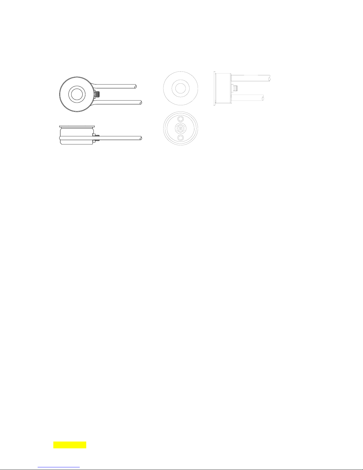
p
Model 880 DEPOSITION CONTROLLER
y
Sensor Specifications
Low Profile P/N 500-042 Right Angle P/N 500-088
Figure 1.1: Standard Sensors.
Operation
Maximum Temperature............................................................. 200 °C
Water Line and Coax Length .................................................... 30 inches
Sensor Mounting ......................................................................Rear of Body, #4-40 Tapped
Feedthrough Installation
Water
Connections ................................................................ Two Required
Type ........................................................................... 1/8 inch OD. Stainless Tubing
Flow Rate .................................................................... 0.2 to 0.3 gal/min.
Water Temp................................................................. 50 °C max.
Electrical
Connections ................................................................ One Coaxial Line
Type ........................................................................... MicroDot Miniature
Materials
(in VAC)
Body and Water Lines ............................................... 304 Stainless
Insulators .................................................................... Alumina
Coax Insulator ............................................................ Teflon
Coax Conductor and Shields ...................................... Copper/Silver
Braze Material ............................................................ High VAC Ni/CR/Cu Alloy
Crystal Quartz with Gold Electrodes
SECTION 1.XX
e page 20 of 275 ^

p
Model 880 DEPOSITION CONTROLLER
y
SIMPLE QUICK GENERALIZED OVERVIEW
SECTION 2.0
for what is the Model 880 used ? .(result). [the problem, the solution]
.deposit material on a target surface with a controlled and repeatable process.
The Model 880 addresses the needs of thin film deposition within the vacuum coating industry.
The main function of the Model 880 is to provide the means for a controlled and repeatable process, which
is the deposition of material on a target surface. [process in which material is deposited on a target surface]
[process that deposits material on a target surface]
(PVD)
<< ii, 2-1 >>
this product is the basis of a controlled and repeatable process.
Without such control, the power [supplies] used to start (or stop) the generation of deposits could be
switched on (or off) at human reaction speeds. Once on, the power [supply] outputs could be altered to vary
the deposit rate, again at human reaction speeds. From the human perspective, the relatively brief time
intervals typically required would be unwieldy at best for accurate control of even a slow process. This
kind of direct human control also assumes that a time versus deposition rate and final thickness is known
for the various deposited materials. Factor in the many physical elements that effect deposition and the
system user, with only time based control, would find it extremely difficult at best for even slowly
accumulating thick depositions, and, for thin depositions, impossible to obtain the desired results, much
less the consistent desired results. The first need is to at least monitor the deposition and know the
thickness (and rate) at any point in time. The next is to be able to control the process based on the
monitored information in real time such that the reaction time between monitor and control is at the needed
speeds. Fortunately, the needed monitor/calculation/control speed is easily within the range of a
moderately priced microprocessor.
The Model 880 has a microprocessor: on each sensor card, on the user interface board (includes
interconnected displays, keys, touchscreens, etc.) and on the communications/control/database board. This
multiprocessor approach provides greater bandwidth and dedication to specialized functions with obvious
benefits: speed, control, etc. The microprocessors used are actually microcontrollers, which can include
A/D, D/A, communications, etc. thus providing cost savings and greater reliability because of the higher
degree of integration. .[in speed and control].
.[Along with an oscillator and crystal sensor(s), the STC-2002 instrument is the basis of a controlled and
repeatable material deposition process system. ].
Along with an oscillator and crystal sensor(s), the Model 880 instrument is the basis of process control and
repeatability within a material deposition system. [of a material deposition system] The Model 880 can be
used to monitor and control the process manually, or to monitor and control the process automatically.
Utilizing the inherent flexibility of the Model 880, there are many possible levels of manual control
(requiring human intervention at user determined points in the process). This is also true of the automatic
process mode. During an automated process, for example, an input state or some other condition can be
made to pause the process for user inspection. If satisfactory, the automated process can be resumed by
another preprogrammed user input. In addition, reactions between monitor and control (response time,
overshoot control, etching vs. depositing, etc.) can be tailored to meet various requirements by user
programmable parameters (discussed in PID control section).
The material deposited on the target may be from a single element or a compound (alloy) to create single or
multilayered metal deposits, lens coatings, the creation of an alloy combination that has special properties,
metalized plastic, etc. The products range from sunglasses, jewelry, automotive decoration, CDs at the low
end to optical lenses, mirrors, filters, semiconductors, superconductors, metallurgical research, etc. at the
high end.
SECTION 2.XX
e page 21 of 275 ^

p
Model 880 DEPOSITION CONTROLLER
y
SECTION 2.1
how is it used ?
First, a few terms and their definitions are needed.
.the material to be deposited is referred to as an evaporant source.
The material to be deposited shall be alternately and henceforth referred to in this manual as an evaporant
source.
.the target surface is referred to as a substrate.
The target surface shall be alternately and henceforth referred to as a substrate.
.the material is known as an evaporant when it has reached sufficient temp/excitation to leave the
source material supply prior to deposition.
The material is known as an evaporant when it has reached sufficient temperature/excitation to leave the
surface of the source material supply prior to deposition. The Model 880 automatically, as it monitors
material deposition rate and thickness, controls the power that generates the evaporant within the bounds of
the user-defined parameters and other programming. The Model 880 is programmed through an LCD
screen with a touch panel overlay. [All choices are deterministic or bounded by a screen specified range.]
All choices are made within groups of predetermined menu selection alternatives or, as in the case of some
data entries, bounded by a screen specified range with software enforcing the range of entry acceptance.
.layered metal deposits, lens coatings, create alloy combinations that have special properties, etc.
With the crystal sensor[s] in the same space as, but not necessarily in relative close proximity to, the
substrate, the crystal sensor[s] should accumulate the same amount (or a ratio) of deposited material as the
substrate. As the crystal frequency is proportionally related to a deposited mass (within specific bounds),
thickness on a substrate can be inferred and deposition rate can be calculated based on thickness values
through the progression of time.
Other dependent factors such as the type of material deposited (as reflected in material density and z factor)
and the physical positioning of the crystal sensor[s] (see tooling factor discussion) are also part of the
deposition calculations and are included among the user programmable parameters of the Model 880.
In a typical case of evaporant stream generation, a high current (or high voltage) power supply is used to
heat the material in a boat, crucible or coiled filament. This power supply is controlled by the control
output voltage of the Model 880 sensor card. This power supply can thus be controlled through the Model
880 either manually or automatically. Manual mode can be used to setup the system before the auto mode
is employed. The power supply, in this case, is manually controlled while the deposition is monitored. In
non-sequencing mode (defined shortly), the final thickness parameter can be set to terminate the process
when reached (evaporant source shutter closure). The power could be switched off via an output relay (a
poor man's controller). In the auto mode (sequencing mode), a user programmable PID loop can be used
for process monitor/power supply control with a relatively high degree of precision based on needed
system speed elements. All methods of evaporant stream generation need power supply control. A power
supply that is controlled by the Model 880 typically provides thermal excitation of the target material by
laser, electron beam (accurate control), resistance heating (low cost/complexity) or sputter (large area)
deposition, each process type having favorable attributes for specific process goals.
Regarding higher level system control, the Model 880 can be programmed to function in this capacity
(keeping in mind failsafe measures). [On a higher level of system control].
Using one of the four user programmable fixed front panel keys and output relays, gates/valves could be
closed and pumps could be activated as a prelude to the previously described automated process. A
pressure monitoring device would signal the Model 880 through an opto-input when the pressure was
correct and the automated deposition would begin. One of the user programmable front panel indicators
could be used to show this and that of other points during the process had been reached.
[For additional information, search the web using "quartz crystal microbalances".]
SECTION 2.XX
e page 22 of 275 ^
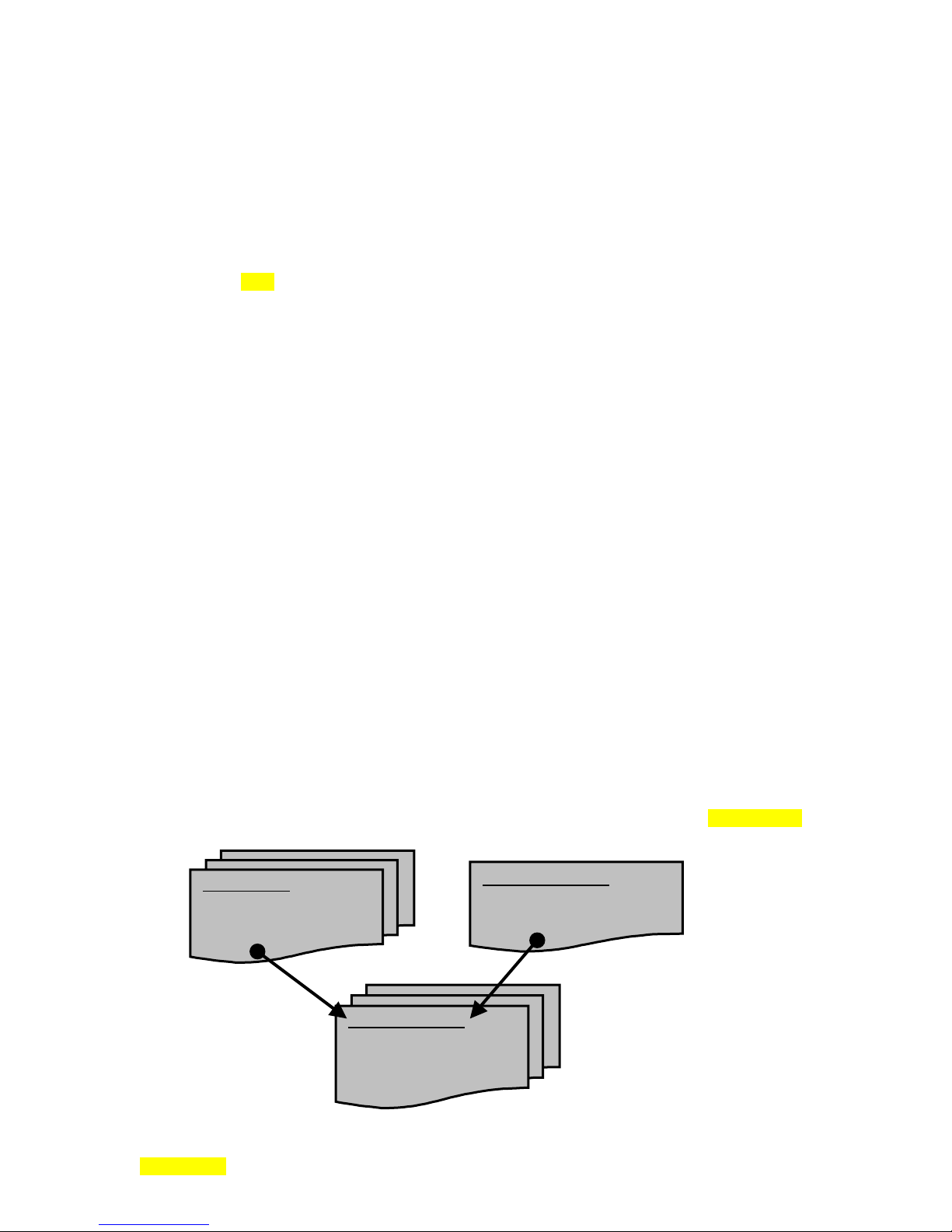
p
p
Model 880 DEPOSITION CONTROLLER
y
<< control loop=2-12 >>
simplest case (seq, non-seq / 1 crystal). 1 process, 1 film, 1 material, 1 crystal, 1 deposit.
Returning to Model 880 specifics, some additional Model 880 terminology definitions must now be given.
Beyond sensor information and power supply control voltage, the Model 880 also allows the user to define
the other parameters that are critical in the deposition process.
In Model 880 terminology, a film is defined as a list of user programmable deposition related
parameters (see XXX). Typically, one material deposition is accomplished per film (describes specific:
material, mechanical setup, timing, etc.). The Model 880 can store up to 99 films (referred to as a film
recipe library). A process is a list of film implementations. Each film implementation is referred to as a
layer (or step in the process). Process layers can use the same film many times or use any combination of
different films (insert figure / see fig. xx).
The Model 880 has 2 basic process control modes: sequencing mode and non-sequencing mode.
While in either one of these modes, manual mode (manual control of power) may be invoked. In addition,
a test mode can be employed to simulate (w/ simulated rate information) a crystal sensor input while in any
combination of the modes just described. Simply put, the sequencing / non-sequencing mode difference is
that of having or not having a process. Non-sequencing mode does not have a process (or at least nothing
named as such). Non-sequencing mode uses 1 implicit process which can run 1 film. The non-sequencing
mode is easiest to configure (user programs an active film). The sequencing mode is more complicated
only by the additional programming of a process[es] that calls out a film or films.
The Model 880 retains the non-sequencing mode for historical compatibility and for simple
depositions.
On the subject of films and processes, that which is referred to as active is that which is queued to
be run when the start sequence is initiated. In other words, except for a co-deposition process, only one
film is being deposited at one time and one process (the active process) is calling out that one film in one of
its steps. When a process is run (start key sequence), it uses the single process that was selected as the
active process (on the Main Menu). Likewise, the film that was selected by the active process as the active
film will become the running film. [The non-sequencing mode has only one inherent unspecified process
and films are manually selected to be active. Only the film selected as active will be run (Main Menu in
non seq mode).] Regardless of mode selection, an active process or active film can be edited (modified)
while a process or film is running but only in a limited manner. This prevents potentially dangerous
situations from occurring. The limitations, that is, the parameters that are not changeable while a process
(or film ) is running include the following:
Film parameters: SS Map Select, Pocket Select, Etching Mode.
Map parameters: CH x Start Mode, Source full power, Source out channel, Indexer Sync Mode.
Min ~~~ XTALS
[3 parameters]
(evaluated at start only except for RE-VERIFY key usage).
Process: Film# of current running step, Process length (no step insertion/deletion).<<<move?>>>
SEQ MODE
1 active process
(process selects 1 or more films)
Up to 9 programmable processes
NON-SEQ MODE
1 implicit active process
(user selects 1 active film)
1 ACTIVE FILM
(up to 99 programmable films)
Film parameters define the
constituent elements of the
osition
de
SECTION 2.XX
e page 23 of 275 ^

p
Model 880 DEPOSITION CONTROLLER
In terms of Model 880 usage, the simplest configurations would be either in sequencing mode with: 1
crystal, 1 oscillator, 1 process, 1 film, 1 material, and 1 deposit or in non-sequencing mode with: 1 crystal,
1 oscillator, 1 film, 1 material, and 1 deposit. Also for these simplest configurations, in either sequencing
or non-sequencing mode, a single sensor input would be employed along with a single control voltage
output (controls power to that which is generating the evaporant). The simplest means of evaporant stream
generation would be resistive heating.
In terms of unit hardware, this translates into an Model 880 with 1 sensor card, 1 output card and 1
input card.
In terms of unit software (menu programming), a specific film is either called by a process (in
sequencing mode) or called directly (in non-sequencing mode). The film, in turn, calls out a specific sensor
map. Except for co-deposition applications, which will be explained elsewhere, only 1 process, only 1 film,
only 1 map can be active (running) at a single point in time. A process can call a different film at each of
its steps (or layers) up to 99 steps.
y
SECTION 2.XX
e page 24 of 275 ^
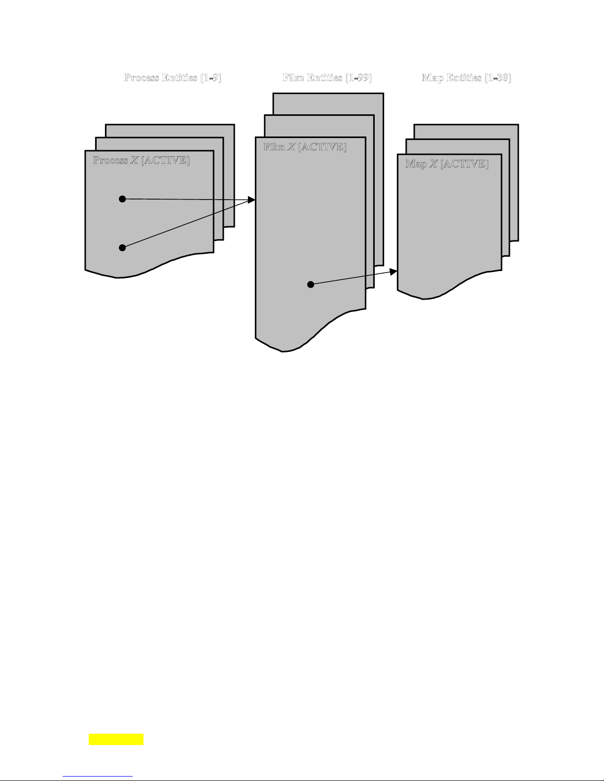
p
Model 880 DEPOSITION CONTROLLER
y
(SEQuencing Mode)
Step# (or Layer#)
Mode: Skip, Stop, Auto, End, Wait
Film #
Thickness
Implicit Process
(NON-SEQuencing Mode)
-OR-
Density
Z Factor
Setpoint Limits
Rate Ramp Power/Time
Soak Power/Time
Deposit Rate Values
PID Loop
Max Power Values
Shutter Parameters
Rate Sampling Values
Film Fail Mode
Xtal Loop Stability/Quality
Xtal Life Bounds
Graph Plotting Values
Map Select
Pocket Select
Source Power Options
Master Tooling
Xtals: Start, Backup, Active
Xtal Drop Filter Mask
Indexer
Channel X:
Start mode
Fail action
Backup List
Tooling
.general case usage .(differences: few) traditional.
The typical usage would not be much beyond the simplest case as described above. This would include
more films (implying more materials), multiple deposits of the same or different materials or more
processes. In addition, a multiple crystal head with an integral either/or shutter is sometimes used as an
input to 2 sensor inputs. Although these configurations represent most systems, the capabilities of the
Model 880 are far beyond these necessities.
input is not supported with this product (no switching with zeroing on a single input, etc.).]
[A multiple crystal head that is used as an input to a
single
sensor
.adding complications (more inputs, relays, crystals, ext. voltages, recorders, comm. terminals,
indexer, etc.)
Examples of added usage complications would be using (or using more) digital inputs, relays, more
crystals, more sensor channels, external I/O voltages, strip chart recorders, communication terminals, ebeam source indexer (model: 376, 379 or 395), etc.
A pendent is supplied for some remote front panel functions and manual mode usage. The pendent plugs
into the front panel of the Model 880 and has a 6 foot coiled cord.
A sensor card has 2 identical sensor inputs and 2 identical analog outputs. The 2 analog outputs, in a single
sensor card system, are typically used as 1 control output voltage and 1 strip chart output voltage. When
multiple sensor cards are used, the strip chart recorder output can be set up on any of the analog outputs but
only one strip chart recorder function per system is programmatically allowed. Each of the two analog
outputs arrive at the external connector in 2 polarities: isolated and a negative version of the isolated
output. A less expensive non-isolated version of the card is TBD? There are slots for 4 sensor cards (1
sensor card is standard in the Model 880). Crystal sensor and control voltage output usage has been
described above. If one of the analog outputs is programmed for strip chart recorder output, a software
menu change can convert the strip chart output into a second isolated control voltage output.
There is another group of 4 slots for either input cards and/or output cards (1 of each type in the first 2 slots
are standard in the Model 880). Input cards have 8 opto-coupled inputs. Output cards have 8 form C
(SPDT) relays. Inputs are typically used to trigger events at some meaningful point in the process or to
SECTION 2.XX
e page 25 of 275 ^

p
Model 880 DEPOSITION CONTROLLER
y
indicate to the system user that some point has been reached. Outputs (relays) are typically used to
open/close shutters on material sources and crystal sensors, but are also used to control many other valves,
relays, solenoids, etc. The card IDs (software addresses) of the PCBs (sensor, input, output cards) are not
unique within their types nor are they programmed by hardware or software. It is the location into which
they are connected that gives them their unique identity (software address).
A communication port is used to interrogate the Model 880. By using a set of commands, various
information can be downloaded or uploaded, front panel control can be simulated, process control can be
modified/stopped/started/driven, etc. .other useages (i.e. limp along).
There are also other useages and subuseages. Some other useages would be test mode and rate sample/hold
mode.
Multiple material co-deposition are also possible with additional hardware and different software described
in a different manual.
SECTION 2.2
how does it work ?
.
crystal osc, crystal sensor
Be forewarned that the general information contained herein is meant only as an overview of the system.
The information presented here does not adequately describe the many hazardous situations that could
occur brought about by the incorrect constellation of valve states, temperatures, pressures and voltages.
The system needs to have safety provisions should inadvertent human intervention cause changes or should
a power failure of any or all parts of the system occur. Safety concerns include electrocution and
explosion.
techniques) needs a number of components. A vacuum chamber provides the space and environment in
which the deposition process will occur. A vacuum is necessary to provide a decreased potential for atomic
collisions and contamination (better dispersion with less impurities). Vacuum pumps are needed: roughing
pump (starts vacuum), cryogenic pump (provides final high vacuum), etc. Relays, valves and solenoids to
control the pumps, pump valves and seal/vent the chamber are needed. A vacuum gauge is needed to
monitor the chamber vacuum. Additional vacuum gauges may be used to monitor other points in the
vacuum system. At the appropriate pressures, the system user can close/open valves, start the deposition
process, etc. A heat/excitation source (electron beam, resistive filament, etc.) to react with the source
material to be deposited, the source material itself, a boat, coil or crucible, etc. into which the source
material is placed, a power supply for the heat/excitation source, and the target (substrate) material are all
needed. A source of water for cooling various components is also needed. An air compressor is necessary
to activate solenoid controlled valves, shutters, etc. Various traps can be used to keep gases clean. Crystal
sensor[s] and attendant oscillator need to be connected to the STC_2002. Shutters are usually placed to
shield the crystal sensors or the source material's evaporant stream, at least during process startup. The
Model 880 typically acts to tie most, or all, of these elements together to control the deposition process.
For e-beam use, a sweeper control unit may also be needed. In multipocket e-beam gun systems, a pocket
indexer or rotator would also be needed.
The roughing pump creates a low vacuum in the chamber first through the open gate valve, the cryopump
and the open rough valve with the purge valve closed. When the desired level of low vacuum is attained,
the roughing pump is powered off as the rough valve between the cryopump and roughing pump is closed.
The cryopump begins to pump the chamber to a higher vacuum (by condensing gas molecules on an
extremely cold surface of a container). When the cryopump reaches saturation, the gate valve is closed and
the purge valve is opened so that the cryopump can be regenerated (a heater may be needed). After
cryopump regeneration is complete (condensed gases have been dissipated), the purge valve is closed, the
gate valve is opened and the pump-down to a higher vacuum using the cryopump continues.
vacuum deposition: vacuum chamber, roughing pump, heat source, evaporated material, p.s.,
cryogenic pump (which condenses gas molecules on an extremely cold surface of a container).
uniform deposition of material in a vacuum, material deposition on crystal and target substrate.
.
A generalized, simple, thin film vacuum deposition system (using physical vapor deposition
SECTION 2.XX
e page 26 of 275 ^
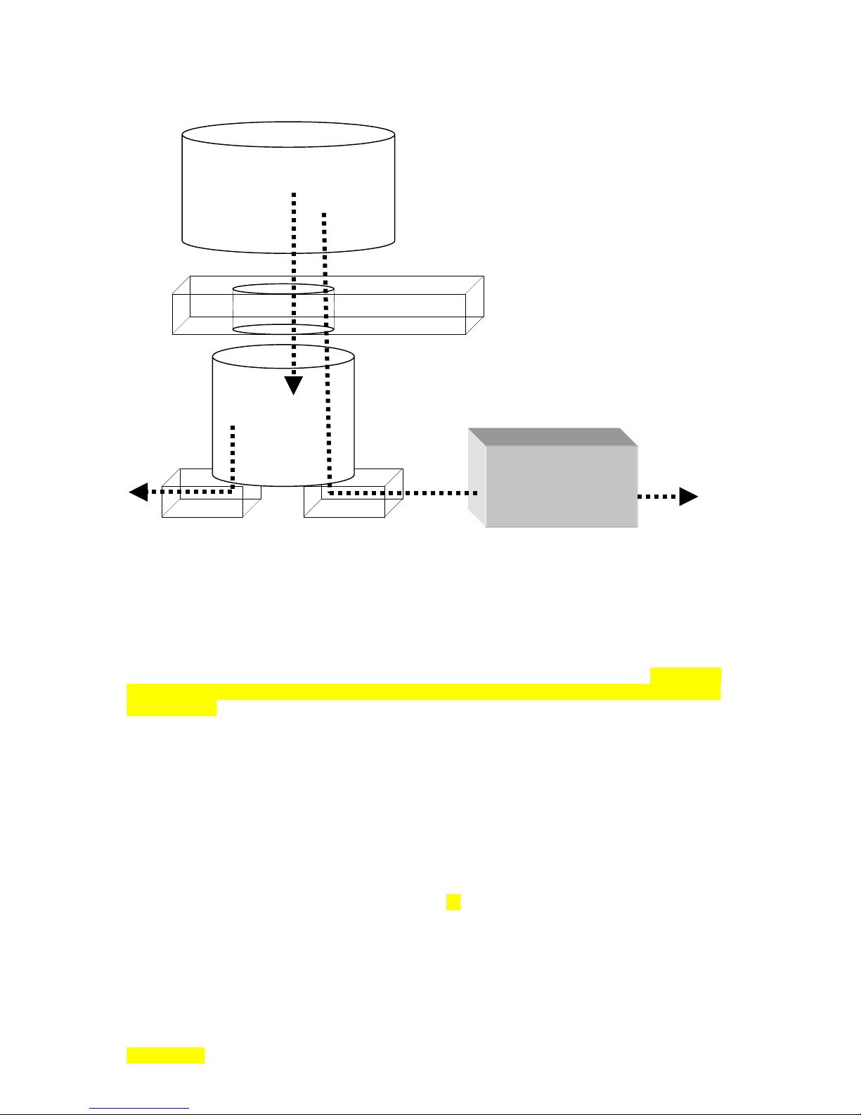
p
Model 880 DEPOSITION CONTROLLER
y
Chamber
Gate Valve
Cryopump
Roughing Pump
Purge Valve Rough Valve
<< crystals 2.2 >>
cal and theory (ch 4, 1
st
page) [keep ch 4-like intact, repetition ok, use see ch 4 to link].
When the chamber is appropriately pumped down, the source material is heated/excited such that molecules
become the evaporant stream and are dispersed.
To reiterate, the source material is known as an evaporant when it has reached sufficient
temperature/excitation to leave the surface of the source material supply prior to deposition. A vacuum is
necessary to provide a decreased potential for atomic collisions and contamination (better dispersion with
less impurities). The Model 880 automatically, as it monitors material deposition rate and thickness,
controls the power that generates the evaporant within the bounds of the user-defined parameters and other
programming. The Model 880 is programmed through an LCD screen with a touch panel overlay. All
choices are deterministic or bounded by a screen-specified range with software enforcing the range of entry
acceptance. The Model 880 can also be programmed through the communication port.
The Model 880 monitors material deposition rate and thickness by means of the crystal sensor, which
occupies the same space as the substrate.
.<< control loop=2-12 >>.
As the deposition process is transpiring within a vacuum chamber, the resonant frequency of a quartz
crystal sensor, also exposed to the same evaporant as the substrate within the chamber, accumulates
deposited film[s] on its surface. The equation in section x7 describes the relationship between the mass of
such a film deposition and the measured frequency of the sensor crystal. Knowing the frequency change
due to accumulated mass, the film thickness can be determined. The rate of accumulated material
thickness can be calculated using the film thickness along with other elements and progression through
time. Contributing factors include crystal sensor placement, material characteristics, etc. The Model 880
numerically displays rate, thickness and power. It graphically displays rate, power or rate deviation.
SECTION 2.XX
e page 27 of 275 ^

p
Model 880 DEPOSITION CONTROLLER
y
As the Model 880 measures the rate of material deposition (in auto deposit mode), it compares this
measured value to a user programmed rate setting. If there is a difference between the actual rate and the
user programmed rate, the control voltage (from the sensor card) is used to generate a feedback to adjust
the deposition source power supply keeping it in compliance with the user programmed rate setpoint value.
This method of Model 880 control has automatic compensation for changing source conditions.
Since there are many different types of deposition power supplies and sources in use today, the deposition
control voltage provided by the Model 880 has been made user configurable: can be wired positive
isolated or negative isolated and menu scaled for 2.5, 5 or 10 volts full scale. The sense of the control loop
can also be set for either deposition or etching applications by menu programming.
To accommodate the extremely wide range of control loop responses required for the diverse deposition
sources available today, a P-I-D type of control loop has been implemented. With this type of control loop
available to the user, it should be possible to achieve very good control of any deposition source (see
section X3X).
All the control loop parameters interact to some degree in the overall response of the control loop resulting
in many combinations of settings that will give equally satisfactory results. Also, the control loop that is
optimized for steady state control will have quite different settings from one requiring fast control
acquisition with minimal overshoot. By supplying real time rate, rate deviation, or control power to the
graph on the Model 880 RunTime display, determination of control loop settings and performance can be
made. By introducing a change into the control system and observing the graphical display responses, it is
quite easy to "tune" the control loop. Source response is another contributing control consideration.
Sources can be categorized as fast responding (electron beam), medium responding (resistive type boats,
baskets, or filaments), or slow responding (Knudsen or induction heated types). User programmable
shutter delay can also be used to achieve good deposition rate control before exposing substrates to the
evaporant stream. Refer to the I/O programming information later in this section and in section x5x of this
manual for a guide on selecting or implementing the logic used to control the substrate and/or sensor
shutter[s].
There are several phases during a deposition layer of the Model 880 related to the source and deposition
rate control. There are three main parts to a deposition layer: pre-deposition, deposition control, and
post-deposition. The pre-deposition parameters control the source and material conditioning prior to the
film deposition. The Model 880 can control a variety of different types of deposition sources. The typical
run cycle phases (rise/soak/rise/soak/shutter delay/deposit/rate ramp/deposit/idle ramp/idle) are for an
electron-beam, resistive element or other thermal source. There are also several film parameters (such as
DENSITY and Z FACTOR) and associated map parameters (TOOLING, WEIGHT) which relate to the
deposition material and sensor calibration. All of these issues will be described in greater detail later in this
manual.
.<< co-dep 3-31 >>.
Co-deposition is the running of 2 process layers simultaneously (2 materials, 2 evaporants, 1 or more
crystals for each of the 2 co-deposition processes). One of the 2 co-deposition processes will be designated
as the one with a final thickness parameter that will terminate the entire co-deposition process. The codeposition process without the final thickness parameter designation will have a parameter specifying its
percentage of the thickness rate of the other process. Another parameter unique to co-deposition is codeposition interaction which specifies quantitatively [by] how much each process contributes (is seen by) to
the other process (the other crystal sensor). Multiple material co-deposition is possible with additional
hardware (2
nd
set of LED/LCD displays) and different software that is described in a different manual.
.<< multi-sensor dep >>.
In addition to the typical configuration of 1 crystal sensor, 1 oscillator, 1 control voltage output, the Model
880 can utilize (by means of the 2
nd
sensor channel and optional sensor cards) multiple sensors to acquire
evaporant stream data at various locations, insuring greater repeatability of process control as well as better
process control (compensating for the vicissitudes of the evaporant stream in location and in time). A
number of user programmable parameters effect multiple sensor depositions. Review Source Sensor Map
SECTION 2.XX
e page 28 of 275 ^
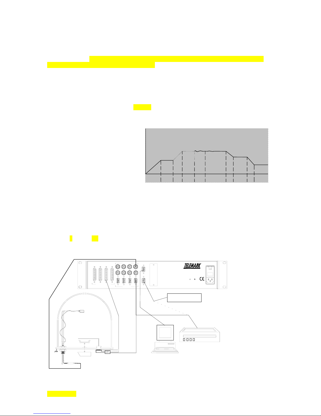
p
y
Model 880 DEPOSITION CONTROLLER
y
chooses the sensors that are part of the multiple sensor group. Since each sensor has a unique parameter
group, programming 2 or more crystals as active automatically invokes an averaging mode. Lost channels
during averaging are handled by menu programmed alternatives (Main Menu/Review SS Maps/Channel
Drop Filter Mask). TBD multiple sensor deposition: averaging multiple, averaging weight, interaction
calibration (among the crystal sensors) . [additive]
Although the Model 880 cannot control multiple depositions (multiple sources as is the case with
co-deposition), but it can maintain other multiple sources (depending on installed and available sensor
cards) such that one source output is controlled while other source outputs can be maintained at a non-zero
power level. This would provide the ability to precondition other materials that could become activated
(controlled) when the currently controlled source reaches its preset conditions. In other words, multiple
source outputs can be providing some level of output to multiple power supplies while deposition control
can be focused on a single source output (moved) among these. The preconditioning mentioned above
would include the soak phases of the deposition process cycle. The soak phase is (or soak phases are)
characterized by power being maintained at a constant level.
Ris e
Note soak power levels in deposition cycle
The more imaginative among us might, at this time, see an opportunity here to use the Model 880 for a co-deposition process (set the
.
Soak
Ris e
Soak2Shutt er
De l a
Depo s it
Rat e
Depos it
Idle
Idle
rate for a source output when active, select another source output as active and then allow the non-controlled output to deposit along
with the controlled output deposition). The problem with this scenario is in the shutter control that is linked to the active output
channel. Alternately, the shutter control could be accomplished with an I/O program but it would not control the process like a true co-
deposition unit nor would it have the same co-deposition oriented amenities
hardware setup discussion
(for actual installation details see Sections x3 & 4 but please read this section first)
.
.necessities: crystal sensor head, osc, bnc cables, vacuum chamber, etc.
Following is a diagram of a typical evaporator installation. This diagram is repeated and described further
in Section 3 (see fig. 3.7).
NOTE: Chart recorder function through memory module connection uses optional hardware and TBD software.
I/O 4 1/O 3 I/O 2 I/O 1
INPUTS / OUTPUTS
CHAMBER
CRYSTAL SENSOR
SENSORS
7 5 3 1
8 6 4 2
7 5 3 1
8 6 4 2
SOURCE
RS232
MEM
COMM OPTION
FUSE: 2 x 2.00 AMP
QUICK-ACTING (F) 250v
90-264 vac, 50-60 Hz, 230VA MAX
!
WARNING
The power cord protective
connected to ground. No user
servicing to qualified personnel.
Memory Module
grounding conductor must be
serviceable parts inside. Refer
SHUTTER
DEPOSITION
SOURCE
OSCILLATOR
SECTION 2.XX
e page 29 of 275 ^
COMPUTER
CHART RECORDER
DATA AQUISITION

p
Model 880 DEPOSITION CONTROLLER
y
Sensor head hardware generalizations (see Section X4 for actual installation details): [discussion]
A vacuum chamber usually has a number of ports with flanges allowing access to the chamber interior.
A typical vacuum feedthrough is a threaded cylindrical piece of metal that fits into a chamber's flange (has
the appearance of a large bolt with nut and washer). A vacuum feedthrough can provide for the passage of
water pipes, compressed air and the electrical connection to the crystal through the chamber wall (or floor)
without leaking under vacuum. The vacuum feedthrough typically has relatively short lengths of pipes
passing through it from end to end, an electrical passthrough consisting of a microdot connector on the
interior side (for the crystal connection) and a BNC connector on the exterior side (for the remote oscillator
connection). Feedthrough placement defines the sensor to feedthrough cable length. Lengths over 30
inches negatively effect crystal stability and usable life. Another pipe may also be provided for compressed
air (for shutter activation).
Electrical connections from crystal sensor through feedthrough to remote oscillator cable.
The typical crystal sensor has a microdot coaxial connector located on the perimeter of its body for
electrical connection to the enclosed crystal. A teflon cable brings this connection to the chamber wall
flange through which it proceeds to the exterior of the chamber via a vacuum feedthrough. The electrical
cable from the sensor head to the vacuum feedthrough should be wrapped around the water lines [securing]
using up all excess length in the process. The chamber, the sensor body, the outer conductor of the
microdot connector and the outer conductor of the BNC connector are electrically interconnected and must
be at earth ground for proper use with the remote oscillator and the Model 880. Grounding also provides
safety benefits and lessens signal noise. The remote oscillator can be connected directly to the exterior of
the feedthrough BNC if room permits. A 6 inch cable is used if there is not enough room. The cable from
the remote oscillator to the Model 880 sensor card can be as long as 100 feet. These interconnects are 50
ohm coaxial cables. Each Model 880 sensor card has 2 crystal sensor inputs (BNC males) that, when
installed in the Model 880, are labeled on the back panel as: 1 and 2 (for sensor card 1), 3 and 4 (for sensor
card 2), 5 and 6 (for sensor card 3), and 7 and 8 (for sensor card 4). The text SENSORS also appears on the
back panel to generally describe the connectors in this area.
Sensor side
The crystal sensor has an opening which presents an area of the crystal surface to the accumulating
deposition material. During setup and initial evaporant material heating/outgassing, this opening on the
SECTION 2.XX
e page 30 of 275 ^
OSC-100A OSCILLATOR
Push to Test
Serial No.
4571
instruments
East Syracuse, NY
Model 880 side

p
n
c
Model 880 DEPOSITION CONTROLLER
y
sensor should be covered to prevent deposition on its surface. Typically a metal shutter (that can be
controlled by an Model 880 output card and solenoid) is moved remotely to cover or expose the crystal
surface and/or the evaporant source. The Model 880 also has a user programmable shutter delay. Tapped
holes are provided on the sensor body for mounting the shutter assembly and/or a mounting bracket to
secure the sensor from movement. The sensor body can be opened so that the crystal can be replaced. A
"solenoid assembly" is used to provide the compressed air to the shutter and can be electrically controlled
by one of the Model 880 output relays. There are available manual shutters activated through a
feedthrough.
The sensor head has a minimum distance to the evaporant source of 10 inches to preclude being struck by
larger droplets that which in turn results in incorrect or no readings. These droplets are not part of the
evaporant stream and are therefore meaningless to the deposition process measurement. The maximum
distance is that which keeps [maintains] the crystal sensor within the evaporant stream. The crystal sensor's
deposition surface should be perpendicular to the evaporation source. The sensor mounting must not be
free to move or vibrate. If the rigidity of the pipes is not sufficient, secure the sensor with a mounting
bracket and screws into the sensor's mounting holes. The evaporant stream needs a clear path (line of sight)
to the crystal sensor's deposition surface otherwise intervening physical elements could cast a shadow in the
evaporant stream.
#4-40 Tap -- 4 holes
Equally Spaced
on o0.731 B.C.
Water Cooli
Microdot Coaxial Conne
The crystal sensor has a pipe bent around most of its circumference for the purpose of transferring heat
away from the crystal. Water is sent through the pipe at a specified minimum flow rate to ensure proper
cooling. The water lines are typically cut and bent to suit the needs of the chamber interior. The pipes, as
previously noted, also provide mechanical support for the sensor. Sensor pipes can be TIG welded or silver
soldered to feedthrough pipes. Swagelok compression fittings are an alternative to welding or soldering that
allow the easy connect/disconnect of pipes (the long pipes attached to the crystal sensor pass through the
Swagelok equipped feedthrough pipes). Covering the pipes and sensor cable as a group with fresh clean
aluminum (or other metal) foil helps dissipate heat from the cable thus allowing higher temperature usage
while minimizing cable movement. This also keeps deposition materials off the pipes and cable for a
cleaner environment when the foil is changed frequently.
Caution
CAUTION Ensure that the water lines are clear of obstructions and restricting bends before
operating the sensor above room temperature. (water flow rate details are in section X?.)
Crystal Sensor Variations: The so called "right angle" crystal sensor has the microdot connector
emerging from the bottom flat surface along with the water cooling pipes (there are no shutter mounting
holes on this unit). The so-called "Bakeable" crystal sensor has fixed length water pipes between the
sensor body and a thick metal disc, which fits into a flange. Also between the sensor body and the thick
metal disc, is a rigid fixed length tubing that houses the electrical connection to the crystal (this allows
SECTION 2.XX
e page 31 of 275 ^

p
Model 880 DEPOSITION CONTROLLER
y
higher temperatures than the teflon cable of the standard configuration). The ends of the water pipes and
crystal connection are on the other side of the thick metal disc (places the 3 terminations outside the
chamber). The electrical connection is terminated with a standard male BNC connector. The "bakeable"
unit, therefore, presents itself on the outside of the flange like the standard crystal sensor. The so-called
"Dual Shuttered Head" has 2 crystal sensors in tandem on a single assembly. As part of the assembly, a
shutter always covers one crystal while exposing the other. When the shutter moves it exposes the
formerly covered crystal and covers the formerly exposed crystal. The installation of a dual shuttered
sensing head is similar to that of the single head. A second sensing input (Sensor 2) is used on the second
crystal channel. (If other Sensor cards are installed, a second sensing input could be selected on these.)
Automatic crystal switching by shutter is accomplished by I/O programming. The primary crystal sensor
channel (Channel 1 in this example) has an associated shutter control bit weight value accessed through I/O
programming (ID#81). The primary crystal sensor channel (Channel 1 in this example) and the secondary
crystal sensor channel (CHannel 2 in this example) are set to the active state by menu programming. By
opening or closing the shutter associated with the primary crystal sensor channel (Channel 1 in this
example), the I/O programming performs the necessary functions for controlling the shutter of the dual
sensor. Proper phasing between the sensor inputs and shutter control can easily be checked by installing a
sensing crystal in only sensor 1 and observing the good and "failed" (absent) sensing crystal when
switching manually between sensor 1 (good) and sensor 2 (failed).
Of course this mechanical method can be supplemented by using 2 sensors without shutters. The primary crystal sensor channel
(Channel 1 in this example) and the secondary crystal sensor channel (CHannel 2 in this example) can also be selected by I/O
programming commands or the active sensor can have a backup crystal sensor channel list that names channel 2 (or the secondary
sensor channel) as the automatic replacement for the failed primary channel. (Sequence would be: fail primary [by command or 3
STATUS menu], backup list provides secondary, re-verify [by command or 3
rd
STATUS menu] reinstates the primary.)
rd
Power Supply Connection: This refers to the high current (or voltage) power supply that provides the
energy to create the evaporant stream. The power supply connection on the Model 880 has the control
voltage that controls the high current (or voltage) power supply. From the Model 880 point of view, this is
known as the source control voltage. The word source describing the source material of the deposition
process in the form of an evaporant stream. Along the bottom of the back panel, in the area where sensor
cards may reside, is the text label SOURCE. This is meant to indicate the 9 pin D-sub connector that is part
of the sensor card. The text labels ½, ¾, 5/6, 7/8 refer to control voltage outputs. In the first sensor card
slot, this indicates control voltage 1 and control voltage 2. Control voltage 1 is meant to control the high
current (or voltage) power supply just described. The 2
nd
control voltage is typically used for the strip chart
recorder control. These identical analog outputs can be interchanged. In fact, their function is assigned by
means of menu programming. If the two functions (control voltage and recorder) are assigned by menu
programming on the same analog channel, the control voltage will have precedence and the recorder
function will be lost. After these programmed outputs are used in a film, a conflicting recorder function
having been lost in this way would require a reboot to recognize a correcting change. The analog output
used for the control voltage output has a number of programmable parameters associated with it. One in
the MAIN/ REVIEW FILMS menu path is: SS MAP SELECT. Another one in the MAIN/ REVIEW MAPS
menu path is: source out channel. Don't overlook the ground connection (connector shell). Shielding goes
a long way toward noise reduction and ultimately contributes to a stable system. [Section 4.6X has more
details]
Strip Chart Recorder Connection: This refers to the Model 880 output from the 9 pin D-sub on a sensor
card that can provide the proper analog signal for a strip chart recorder. Along with the hardware
connection, the analog output used for the strip chart recorder has a number of programmable parameters
associated with it. Two in the MAIN/ EXEC/ SYSTEM CONFIG menu path are: recorder function I/O
control and recorder out channel. Don't overlook the ground connection (connector shell). Shielding goes
a long way toward noise reduction and ultimately contributes to a stable system. (See Power Supply
Connection above) [Section 4.7X has more details]
RS232 Communications Connection: Located in the approximate center of the back panel and labeled
with the text RS232 is a male 9 pin D-sub connector for the purpose of communications with a PC or
SECTION 2.XX
e page 32 of 275 ^

p
Model 880 DEPOSITION CONTROLLER
y
laptop computer. A straight through cable (that is, pin 1 at one end is connected to pin 1 at the other end,
pin 2 to pin2, etc.) cannot be used. A cable configuration known as a null modem cable needs to be used.
A diagram of the connections is shown in section 4.11XX. Operations (start/stop) and menu programming
normally done through the front panel controls can be accomplished remotely by means of the interface.
Software downloads that become the product firmware can also be accomplished through this port. Menu
programming needs to be set for the proper baud rate and communication protocol
(Main/Executive/Comm. Setup menus) [Section 3.15X and 3.16Y has more details]
Grounding Stud: Located on the back panel near the AC power connector/switch, the ground stud is a
threaded screw embedded in the back panel providing an electrical connection to the chassis ground of the
Model 880 as well as to the ground connection of the AC plug. This should be used to maintain the system
equipment grounds, including the chamber, at the same potential as earth ground. As there are many
potential sources of high-energy noise that are part of a deposition system, implementation of this ground
system can substantially reduce noise resulting in improved system stability. [Section 4.XX has more
details]
Input Card Options: An opto-isolated input card can be configured in a number of ways. Inputs can be
isolated or non-isolated, internally powered or externally powered (individually or as a group). Jumpers on
the input card are used to make the selections. All of the opto-coupler LED cathodes are brought out to the
25 pin D-sub female (i.e. pins 3,6,9,12,14,17,20,23
[(-) Input Pins]
). The opto-coupler LED anodes are
brought into a jumper header (JP1) where each of the anodes can either be routed to a voltage source or
sent out to the 25 pin D-sub female (i.e. pins 2,5,8,11,16,19,22,25
[(+) Input Pins]
). The voltage source itself
is further selectable on a separate 3 pin jumper header (JP2) such that an internal voltage (+5VDC) can be
selected or an external voltage can be selected (comes in on pin 1 of the 25 pin D-sub female). The
voltage source, regardless of the JP2 selection, can therefore be applied to all of the anodes when JP1
selects the voltage source. Any one or more of the anodes can be alternately routed through JP1 to keep
them isolated from the other anodes and the voltage source. Jumpers can short from the center to one of the
ends. Since there are 8 anodes, there are also 8 JP1 sections. The depiction below is a generalization of a
single LED input (1 of 8). [Section 4.8 has more details]
cathode D-sub
[(-) Input Pins]
D-sub
JP1
[(+) Input Pins]
anode
int. pwr.
JP2
D-sub (pin 1 only) ext. pwr.
dig. gnd. D-sub (pin 13 only)
SECTION 2.XX
e page 33 of 275 ^

p
Model 880 DEPOSITION CONTROLLER
y
Installation/Removal of Sensor Cards, Input Cards, Output Cards: Although other combinations are
possible, the following procedure is recommended for field installations and removals. There are human
safety issues and component damage issues that are addressed by this procedure. Please read this
procedure in its entirety first before commencing the actual work. Return of the unit is preferred.
1. Disconnect all electrical connections to the Model 880. This includes all I/O connections, Sensor card
connections, RS232 connections, other communications connections, pendent, memory card connections,
ground wires and especially the power cord connection. Ensure that the power cord is removed from the
back panel IEC 320 connector and that the Model 880 unit is on a properly grounded rubber mat (or
equivalent). The person doing this work should also be properly grounded by wearing a grounding strap.
2. Remove the six screws that secure the top cover. Remove the top cover. Store these items together in
anticipation of reassembly.
3. With the top removed, look inside the Model 880. Disconnect the power connection between the IEC
320 connector/switch assembly (mounted on the back panel) and power supply. This will be a 3 position
Molex type connector housing plugged onto a mating header that is part of the power supply. This will
allow for the removal of the back panel. Next, disconnect the DC power wiring harness from the other end
of the power supply. This will be a 6 position Molex type polarized connector housing. Finally,
disconnect the 2 pin connector from the LED display board. The wiring harness is now free to move with
the bus board. Refrain from flexing the wiring harness at the solder points on the bus board.
4. Locate the two screws on each of the side panels that hold the back panel in place. These are located on
the side panels near the back panel (the screws go through the side panels and into the back panel).
5. The back panel/PCB assembly can be pulled straight back away from the STC_2002. The back panel
assembly will include the power switch/receptacle/wire harness assembly, the PCB cards secured to the
back panel, and the bus PCB that interconnects the other ends of the secured PCB cards. Before pulling
the back panel away from the main unit, please note that the PCB that provides the RS232 connection on
the back panel will disconnect from a PCB on standoffs running parallel to the front panel. This connection
will obviously need to be reconnected upon reassembly. This is why the back panel / PCB assembly must
be pulled out straight away from the unit: the header pins may be bent otherwise.
6. With the back panel / printed circuit board assembly on the grounded mat, remove the interconnecting
bus PCB from the secured back panel mounted PCB cards taking care to pull the bus board straight out to
avoid bending header pins. Place the bus PCB on the grounded mat.
7. PCB cards may be added or removed from the back panel at this time. PCB mounting hardware is
removed or added. Securing the PCB cards to the back panel is accomplished by use of the connector
mounting hardware.
8. Carefully align all back panel secured PCB connector headers with the mating socket headers on the bus
PCB. Start alignment at one end of the bus board, holding each back panel secured PCB lightly in place
until all are aligned then press on the bus board such that all bus board connectors are fully engaged with
the mating back panel secured PCBs.
9. Introduce the back panel assembly back into the unit moving it horizontally across the table while
maintaining its orientation such that the back panel remains parallel to the front panel. Ensure that the
power connector harness wires are not pinched or that the insulation on the wires is not damaged. As the
PCB (that provides the RS232 connection on the back panel) nears its mating connection, align the
assemblies such that the header pins correctly engage and insert straight.
10. Secure the back panel assembly to the side panels with the 4 screws previously removed.
11. Check PCB interconnections for bent pins or misalignments. If there are problems, reverse process to
the point needed to correct the problem.
12. Reconnect the switch/IEC wiring assembly connector housing to the power supply header. Reconnect
the DC connector housings to the power supply header (6 positions) and LED display board (2 positions).
The connectors are polarized.
13. Replace the top cover and secure it with the 6 screws.
14. Reconnect the power cord into the IEC connector.
15. Power on the unit.
SECTION 2.XX
e page 34 of 275 ^

p
ere
Model 880 DEPOSITION CONTROLLER
y
bus board
disconnects
h
DC
Header
power supply header
IEC switch/connector
back panel
Pendent:
Also called a hand controller,
may be connected by means of the front panel jack labeled Manual
Control when certain front panel functions need to be duplicated remotely or when intending to utilize the
Manual mode. When not in use, the pendent may be left plugged into the Model 880 unit or it may be
removed. The pendent does not contain any active electronics nor is it polled to check for its presence.
LCD contrast/bias: The optimal viewing is designed for perpendicular to about 45° up and about 45° from
perpendicular to either side. Within a few minutes of powering the unit on, there will be some thermal drift
effecting color but this should be relatively unnoticeable. If, however, the unit will be in an environment
having elevated ambient temperatures (above 30° Celsius), the LCD contrast/bias should be set to low
through menu programming (Main/Executive/System Configuration menus).
Graphical Display: Although no hardware other than the LCD display is associated with this item, it needs
to be setup. Three film parameters need to be programmed: Plot Vert Scale Volts, Plot Horiz Scale H, Data
Plot Type. The graphical display, as the name implies, displays, in graph form: rate deviation, rate or
power.
Rack Mounting: Rack mounting ears and screws are supplied with the Model 880 for the purpose of
mounting the unit in a standard rack.
Rubber Feet: Rubber feet are not supplied with the Model 880. The anticipated usage of the product is
within a rack. If, however, in the unlikely case where the usage will be on a shelf, table or some other flat
surface, rubber feet should be used to prevent sliding with the possible resultant damage. They should be
of the type that sticks on the bottom of the unit. These can be purchased cheaply at many retail outlets.
The waxed paper is first removed from each foot. The foot is then applied to the bottom of the Model 880
such that they are placed in each corner an inch from the 2 corner surfaces. Subsequently, if the unit will
be rack mounted, remove the rubber feet.
System Hardware Connections: Except for the generalized previous descriptions, complete system
hardware setup is beyond the scope of this manual. Consult the manuals for each of the components in the
system. The sum of the manuals is less than the whole: Be forewarned that the general information
contained herein is meant as an overview of the system only, an overview to describe how the Model 880
integrates with the other components in the system and some of its' typical usage's. The information
SECTION 2.XX
e page 35 of 275 ^

p
Model 880 DEPOSITION CONTROLLER
y
presented here does not adequately describe the many hazardous situations that could occur brought about
by the incorrect constellation of valve states, temperatures, pressures and voltages. The system needs to
have safety provisions should inadvertent human intervention cause changes or should a power failure of
any or all parts of the system occur. Safety concerns include electrocution and explosion. .(reiteration of
above).
programmable hardware setup discussion
(for detailed setup see Section x3 but please read this overview section first)
Synopsis:
Select mode: sequencing/runtime, sequencing/test, non-sequencing/runtime, non-sequencing/test.
Optional selects: manual mode and test mode. Select memory configuration: factory, purged, as-is.
Program system parameters. Program film parameters (for a single film or multiple films) and process
steps. Set active process. Select crystal. Start process.
The versatility of the Model 880 translates into many modes, parameters and configurations all of which
arrive from the factory in default states. Except for the Input card hardware configurations (uses jumpers),
all modes, parameters and configurations are menu programmable. The VAR or end user must tailor the
unit to work with specific hardware for the desired deposition process.The VAR or end user must tailor the
unit to the specific hardware and deposition process at hand.
Run time mode is the general name for the mode used for the deposition process whose screen can
always be brought forth from any menu screen by pressing the fixed front panel key labeled STATUS.
[A second press of the STATUS key while the Run Time screen is displayed will invoke a screen showing, among
other elements, active control output channel[s], pocket number[s] and power % expended on each. A third press of the
STATUS key beginning when the Run Time screen was displayed will invoke a screen showing, among other
elements, active sensor channels and their states, rates, thickness', stability's and crystal lives. This second screen can
be used to fail or reinstate (re-verify) a crystal.
has no effect on the deposition thickness.]
Zero thick
ness at this level is used for tooling setup or diagnostics and
The specific functional run time mode must be chosen: sequencing or non-sequencing. Either of
these modes can be further switched between the normal run mode and the test mode. This results in 4
mode choices: sequencing/run, sequencing/test, non-sequencing/run, non-sequencing/test. Manual mode
(manual control of power) can be selected while a process is running by pressing the fixed front panel
MANUAL key with the pendent connected.
At the same time that these choices are being made, the programmable memory can be kept as it
is, purged or set to factory defaults. A memory change can effect film parameters, process steps, run time
mode, system configuration, I/O programming, process accounting, and communication parameters.
Elsewhere in this manual (appears section 3.21) are tables and lists depicting memory element values after
purge and after factory [settings] are invoked. This memory information by itself is also listed later in this
section.
A film is programmed by selecting the film number (on the main menu), moving through the
associated parameter list, and changing the values as needed. Some of the film parameters are not
accessible or viable when another related film parameter predicates their availability. Up to 99 films can
be programmed. In non-sequencing mode, only 1 film can be run at a time, as there is only one implicit
process. In sequencing mode, a process can call for a film in a process step. There can be up to 99 steps in
a process and up to 9 processes. A process is menu programmed by building each line (step) with a mode
value, film number and thickness value.
In the non-sequencing mode, an active film must be menu selected (1 of 99). In the sequencing
mode, an active process must be menu selected (1 of 9). In either case, active indicates that this is the film
or process that will become active when the process starts (initiated by the front panel START key). In
addition, neither a film nor a process may be altered by editing when either is being used in a running
deposition (for safety reasons).
Some system configuration parameters also determine the status of some film and map
parameters. Example configuration parameters that fall into this category are: need s/s card x and I/O slot
x type. Check the film parameter dependency list in section X1.8X to find the parameter of interest (all
parameters are listed there). Finally, set the status of the controlling parameter such that it allows the
SECTION 2.XX
e page 36 of 275 ^

p
Model 880 DEPOSITION CONTROLLER
y
parameter of interest to be accessible and appropriately set. Dependencies are also listed later in this
section.
There are some basic parameters that need to be setup. The Density and Z-Factor can be
obtained from table x4.1, in section x4.3 [Review Films menu]. Tooling [Review Source Sensor Map
menu] for crystals can be determined empirically by running a trial deposition and using the equation (this
will be found in section x4.2):
Tooling = 100 X (Substrate Thickness / Displayed Thickness).
Generally, Tooling is greater than 100% when the sensor sees less deposited material than the substrate
(e.g. the sensor is further from the evaporant source than the crystal sensor). Generally, Tooling is less than
100% when the sensor sees more deposited material than the substrate (e.g. the sensor is closer to the
evaporant source than the crystal sensor). If 2 crystal sensors are used (assuming a single sensor card is
installed), Start Xtal (crystal) must match the hardware and positioning used. Obviously, the two crystal
sensors cannot occupy the same space. Therefore each crystal sensor will have a different tooling factor.
Crystal sensor tooling is coordinated by the sensor map menu that selects the sensor along with other sensor
properties. The channel specific applicable Review SS Map menu parameter is CHx Tooling. There is
also a Master Tooling parameter (Review SS Map Menu) that can be used change the ratio of all the crystal
sensors simultaneously in addition to the individual channel tooling. This can be thought of as a global
offset or multiplier used to alter the tooling of all
active crystal sensors. In any case, the Tooling factor is
the attempt to describe the ratio of deposited material between the crystal sensor and the substrate.
Max Power Limit, Deposit Rate, Soak Power Value, Power Ramp Time, Power Soak Time,
Setpoint thickness and time limits need to be described. With these parameters entered, the Test mode
could be utilized to check the process behavior. The Max Power indicators show when the Max Power
parameter has been exceeded (LED blinks, LCD alternates with MAX!). To reiterate, the TEST mode only
effects the crystal sensor information being processed, it does not effect anything else (this includes the
control output voltages). This is not the point at which to begin experiments with a live system. This
section is meant to provide a discussion of the issues to familiarize the user with functional themes. Please
read further.
[OK. Try these parameters while in the Test mode and with no external connections especially the
control output voltage unconnected: Max Power Limit:75%, Deposit Rate:3.7, Soak 1 Power Value:50%,
Power Ramp 1 Time:1:00, Power Soak 1 Time:1:00, Setpoint thickness limit:9.999 and time limit:1:11,
Data Plot Type:Power. With the above entered, and still in the Test mode, press the fixed front panel Start
key + touch key Reset / Start Proc in sequence three times. The assumption is made that factory defaults
are in effect. The Test mode is entered through the MENU, SERVICE, TEST OFF, ACCEPT keys. Film
parameter entry: fixed front panel Menu key + touch key Review Film.]
.informational only, no connections except power (see fig. 3.6, read or copy 3.1,3.2)
alternates: boat, srt-400, e-beam.
When the Model 880 sensor card control voltage output is connected to the evaporant power supply,
Review Source Sensor Map parameters need to be selected for a proper interface (
SOURCE FULL PoWeR, SOURCE MAX PoWeR
) and the Map itself needs to be selected by a Film parameter
SOURCE OUT CHaNneL,
(SS MAP SELECT). Following this, other power supply related parameters must also be contemplated.
Some thermal excitation alternatives include: electron beam: wire fed electron beam source, high vacuum
e-beam w/ small (~2cc) crucible, fixed pocket (large and small), rotary pocket indexers; resistive heater
sources: metal filament boats, coils, oxide crucibles (all for organic material deposition). Crucible
capacities can range from a fraction of a cc to over 500cc. The input control requirements of the high
current (or voltage) power supply should be found in the power supply documentation. Don't assume there
is a standard. With the Model 880 control voltage output controlling the power supply for these thermal
sources (the 2
nd
control output voltage used for power supply control is typically employed for the recorder
function), the film parameters effecting power (processes depend upon films) are:
Soak 1 Power level Value 0.0 to 100.0%
Power Ramp 1 Time (to pwr level) 0 to 99:59 MM:SS
SECTION 2.XX
e page 37 of 275 ^

p
Model 880 DEPOSITION CONTROLLER
y
Power Soak 1 Time (@ pwr level) 0 to 99:59 MM:SS
Soak 2 Power level Value 0.0 to 100.0%
Power Ramp 2 Time (to pwr level) 0 to 99:59 MM:SS
Power Soak 2 Time (@ pwr level) 0 to 99:59 MM:SS
Soak 3 Power level Value 0.0 to 100.0%
Power Ramp 3 Time (to pwr level) 0 to 99:59 MM:SS
Control Loop –P-roportional term 1 to 9999
Control Loop –I-ntegral term 0.0 to 99.9 sec
These parameters are presented
here for the purpose of name
familiarization and categorization
of power related parameters
across menu and screen
Control Loop –D-erivative term 0.0 to 99.9 sec
Max Power Limit 0.0 to 100.0%
Abort Max Power SW OFF/ON
Max Power Dwell 0:01-99:59 MM:SS
Control Loop Qual Limits 0 to 9
Plot Vert Scale Volts 1, 5, 10, 50, 100 ⇐ Graphical display function
Plot Horiz Scale H 1 to 600 samples ⇐ Graphical display function
Data Plot Type Rate /Power /Rate Deviation ⇐ Graphical display function
Source Sensor Map Select 1 to 9
Etching Mode Off / On (
(Selects the Map that contains Source Sensor analog output parameters)
Rate Direction can be Positive or Negative)
The Power Related RunTime Screen parameters are:
(Crystal Quality Indicator Select) L/Q, Loop x, Qual xx
(Manual mode) (fixed front panel key)
(Manual mode) (pendant arrow keys [increase / decrease power manually])
(Manual mode) (2
(Manual mode) (1
(Manual mode)
nd
STATUS screen arrows: [increase/decrease power manually])
st
STATUS screen: zero power key [LCD] on non-active channels)
(2nd STATUS screen: zero thick key [LCD] no effect on material thickness)
(Manual mode) (2nd STATUS screen: force fail key [LCD] fail/verify crystal channels)
The Power Related System Configuration values are:
Menu path: Main/Executive menu/System Configuration]
Recorder Functions Rate, Rate Deviation, Power, Thickness, Computer Remote, I/O, Off
Recorder Analog Output ChaNneL
1 to 8 Channels (select 1 only)
[note possible conflict w/ Source Analog Output]
Need Source / Sensor Card x on/off
The Power Related Review Source Sensor Map values are:
Source FS Voltage Scaling PoWeR*
Source Max PoWeR 0.0 – 100.0%
Source Analog Output CHaNneL 1 to 8 Channels (select 1 only)
2.5/5/10 Full Scale VOLTS ⇐
The Power Related Service Menu values are:
Menu path: Main/Review SS Map]
see Power Supply input requirement
Menu path: Main/Service]
(Memory Contents) as is (no modification), purged, factory (defaults) [see section x3.21x ]
note film parameter changes
(Reset) Arm reset, reset armed [Provide a product reset when back panel power
switch is not accessible. Also, use to generate ACCEPT key if not
present (e.g. to end the Test mode when in the Test mode).]
*NOTE: Of primary concern when connecting evaporant power supply to the sensor card.
Dependencies
[Prerequisite states that must be in effect for the following parameters to be fully functional]
The Power Related Film Parameter Dependency List is:
Max Power Dwell Film Parameter: Abort Max Power SW = ON
SECTION 2.XX
e page 38 of 275 ^

p
Model 880 DEPOSITION CONTROLLER
y
The Power Related RunTime Screen parameter Dependency List is:
(Crystal Quality Indicator Select) L/Q, Loop x, Qual xx Film Parameters
(Manual mode) Running Process + Pressing fixed front panel MANUAL key +
attached Pendent (or on 1
st
STATUS screen: , , zero CH x)
(process start) .PerformCarry out the following 2 key sequence up to 3 times.
Press the fixed front panel START key + 1 of 4 touch panel keys:
Break Wait, Next Layer, Restart Layer, Reset / Start Process
(see figure in end of section 2.7). Use the appropriate touch key for the
task at hand. If unsure, use Reset / Start Process key in all 3 sequences.
Please read and understand this manual before starting a live process.
.options
material selection (4-2 to 4-6).
substrate selection (4-2)
tooling factor (ch 4, 4-3)
<< fig. 10-9, equip list 10-10 >>
<< sensor inst. 11-3 >>
SECTION 2.XX
e page 39 of 275 ^

p
Model 880 DEPOSITION CONTROLLER
y
Initial Programming Setups (menu parameters)
system configuration programming (factory/ default settings, stand alone / computer controlled)
If the Model 880 has: arrived directly from the factory or the factory settings key has been menu selected or
the purged settings key has been menu selected, the following specifies the parameter values in effect.
The following information will be repeated in later sections in greater detail along with additional related
information. The intent here is to introduce the reader to baseline values and consequently what must be
altered for the intended use. Purge values are listed first, followed by the factory differences
.
Film Parameter values after purge: Communication values after purge:
[non-SEQ adds "Final Thick Limit=0.0 KÅ"]
Material Density 1.00 gm/cc COM/IO Lock Code 0
Material Z-Factor 1.000 Keyboard Beep ON
Setpoint thick limit 0.000 KÅ RS232 Baud Rate 9600
Setpoint time limit 0:00 MM:SS RS232 Protocol Sycon
Soak 1 Power Value 0.0%
Power Ramp 1 Time 0:00 MM:SS
Power Soak 1 Time 0:00 MM:SS
Soak 2 Power Value 0.0% LCD Contrast MEDIUM
Power Ramp 2 Time 0:00 MM:SS Password Lock # 0
Power Soak 2 Time 0:00 MM:SS Run Number 0
Soak 3 Power Value 0.0% Recorder Functions Off
Power Ramp 3 Time 0:00 MM:SS Recorder Output Channel 1
Deposit Rate 0.0 A/S Clock Time no change (HH/MM/SS)
Rate Ramp Mode OFF (w/o battery: 00/01/00)
New Deposit Rate 0.0 A/S Clock Date no change (MM/DD/YY)
Rate Ramp Time 0:00 MM:SS (w/o battery: 01/01/01)
Rate Ramp Trigger 0.000 KÅ Need SS Card 1 ON
Control Loop P 100 Need SS Card 2-4 Off
Control Loop I 1.0 secs I/O Slot x Type Disabled
Control Loop D 1.0 secs
Max Power Limit 0.0% Run Time Screen after PURGE:
Abort Max Power SW ON
Max Power Dwell 0:30 MM:SS PROCess 1
Shutter Delay Mode Off Layer #
Shutter Delay Timeout 0:30 MM:SS FILM (film in use) 1
Shutter Delay Quality 10 SRC
Rate Sampling Off XTAL (blank)
Sample Interval 0:30 MM:SS MAP# 1
Sample Dwell Time 0:30 MM:SS RUN time 0:00
Sample Quality 10 PHASE time 0:00
Sample Alarm Time 0:30 MM:SS RUN# 0
Film Fail Mode Time Power (Graph parameter) Rate Deviation
Control Loop Quality L 0 Crystal Quality L/Q
XTAL Stability S 0
XTAL Life Bounds 0.0% MAIN MENU Screen after PURGE:
Plot Vert Scale Volts 100
Plot Horiz Scale H 1 Review Film (film 1 will be reviewed)
Data Plot Type RATE DEV Review SS Map (Map 1 will be reviewed)
SS Map Select 1 Next Process 1
Pocket Select 0 Review Processes
Etching Mode Off (pos/neg)
note1: non-sequencing mode does not have this function (non-SEQ: ACTIVE FILM is 1).
System Configuration values after purge:
(note conflict: Source Sensor Out is also1)
Memory Module IFC OFF/ON (optional)
(Source Control Volts Channel)
1
(Process 1 will be reviewed)
(where x = 1 to 4)
note1
note1
(Sample/Hold = blank)
SECTION 2.XX
e page 40 of 275 ^

p
Model 880 DEPOSITION CONTROLLER
y
Review SS Map values after purge:
Source Sensor Full Power Volts 10 volts
[need 3rd Source Sensor Card for Channels 5 & 6]
Source Sensor Max Power Value 0.0% Channel 5 Start Mode OFF
Source Sensor Analog Output Chnl 1 (Channel Select) Channel 5 Fail Action Mode NONE
Master Tooling Value 100.0% Channel 5 Backup List 0
Minimum Start Xtal Channels 1 channel Channel 5 Tooling Value 100.0%
Minimum Backup Xtal Channels 0 channels Channel 5 Weight 100.0%
Minumum Active Xtal Channels 1 channel Channel 6 Start Mode OFF
Xtal Channel Drop Filter NONE Channel 6 Fail Action Mode NONE
Indexer Synchronization Mode NONE Channel 6 Backup List 0
Indexer Synchronization Time 2 seconds Channel 6 Tooling Value 100.0%
Channel 1 Start Mode OFF Channel 6 Weight 100.0%
Channel 1 Fail Action Mode NONE
[need 4th Source Sensor Card for Channels 7 & 8]
Channel 1 Backup List 0 Channel 7 Start Mode OFF
Channel 1 Tooling Value 100.0% Channel 7 Fail Action Mode NONE
Channel 1 Weight 100.0% Channel 7 Backup List 0
Channel 2 Start Mode OFF Channel 7 Tooling Value 100.0%
Channel 2 Fail Action Mode NONE Channel 7 Weight 100.0%
Channel 2 Backup List 0 Channel 8 Start Mode OFF
Channel 2 Tooling Value 100.0% Channel 8 Fail Action Mode NONE
Channel 2 Weight 100.0% Channel 8 Backup List 0
[need 2nd Source Sensor Card for Channels 3 & 4]
Channel 8 Tooling Value 100.0%
Channel 3 Start Mode OFF Channel 8 Weight 100.0%
Channel 3 Fail Action Mode NONE
Channel 3 Backup List 0 I/O SETUP values /programs after PURGE:
Channel 3 Tooling Value 100.0%
Channel 3 Weight 100.0% I/O Programs A & B Cleared
Channel 4 Start Mode OFF Memory Menu A
Channel 4 Fail Action Mode NONE Operate Menu Running
Channel 4 Backup List 0
Channel 4 Tooling Value 100.0%
Channel 4 Weight 100.0%
Film parameter differences: factory restore has: max power limit set to 50% (purge = 0%).
Processes Step differences: As an example, the following is the difference between a factory setting and a
purged setting for PROCESS# 3. The factory setting has, for the first and only step (step 01):
MODE=AUTO, FILM#=3, and THICK(Kå)=0.300. The purged setting has an END line as the first and
only step (considered cleared). If process 3 were run with factory settings, AUTO mode would be invoked
using film #3 and running until a final thickness of .300 Kå was achieved.
If process 3 were run with purged settings, the END command would be encountered immediately thus
stopping the process. The table below shows this information as well as information for the other
processes.
Factory Settings table for All Process Numbers:
Proc# 1 Proc#2 Proc#3 Proc# 4 Proc#5 Proc#6 Proc#7 Proc#8 Proc#9
STEP 01 01 01 01 01 01 01 01 01
MODE AUTO AUTO AUTO AUTO AUTO AUTO AUTO AUTO AUTO
FILM# 1 2 3 4 5 6 7 8 9
THICK 0.100 0.200 0.300 0.400 0.500 0.600 0.700 0.800 0.900
All factory Processes have END as STEP 02.
SECTION 2.XX
e page 41 of 275 ^

p
Model 880 DEPOSITION CONTROLLER
I/O programs are not factory restored because of the danger involved. Factory restore will not, therefore,
clear or restore the factory I/O program[s] (it leaves them unchanged). Purge will, however, clear I/O
programs. These selections will cause the unit to REBOOT with the new configuration in effect. The
section describing the SERVICE menu will describe these elements in detail. As seen in the above lists,
there are groups of settings (Film parameters, System configuration, Communications, Processes, I/O
programs, etc.) that will be included in these configurations. Valuable process programming could be
lost. The BYE key can be pressed to leave the SERVICE menu without changing anything.
If the password is forgotten and programming has not been saved in some other
media, call the factory to eliminate passwords without purging memory.
.deposition programming (text discussions, the next section has details)
input/output programming (text discussions, the next section has details, ch 5).
y
I/O programming Introduction
The I/O programming is what controls the opto-isolated inputs on the Input card and the isolated relay
contacts on the Output card. Similarly controlled, the front panel has 4 LEDs that are intended as user
controlled outputs, 4 user programmable fixed keys that are intended as user controlled inputs and the
pendent whose alternate function is user I/O programmable inputs. This I/O programming control extends
to input acquisition of front panel key presses, elements of film deposition run cycle states (i.e. rise, soak,
deposit, idle, etc.), various process state conditions, process switching, various crystal states or events,
setpoint conditions, etc. I/O programming also controls by means of general variables, events and states.~
The I/O programming can discern whether an input has changed state and when it has changed state. When
an input has both state information and temporal information, it is known as an edge event condition. When
an input has only the state information, it is known as a steady state condition. Outputs also have analogous
edge event and/ steady state conditionality. The output result is, correspondingly, either a pulse or a steady
state.
To reiterate, Run time mode is the general name for the mode used to run the deposition process
whose screen can always be brought forth from any menu screen by pressing the fixed front panel key
labeled STATUS. The Run time mode of the Model 880 has 2 basic process control modes: sequencing
mode and non-sequencing mode. While in either one of these modes, manual mode (manual control of
power) may be invoked. The specific functional run time mode must be chosen by menu selection:
sequencing or non-sequencing.
In addition, a test mode can be employed to simulate a crystal sensor input (w/ simulated rate
information) while in any combination of the modes just described. Simply put, the sequencing / nonsequencing mode difference is that of having or not having a process. Non-sequencing mode does not have
a process (or at least nothing named as such). Non-sequencing mode uses 1 implicit process which can run
1 film. The non-sequencing mode is easiest to configure (user programs an active film). The sequencing
mode is more complicated only by the additional programming of a process[es] that calls out a film or
films.
Inputs, outputs and all the other states and events have a numeric representation called an ID number. An
ID number is used to numerically represent: inputs, outputs and all the other states and events. They can be
named by their description and classified by state/event condition. A table containing all I/O programming
events and states can be found in this manual. After locating an event or state that the user needs as a
pivotal point in their process, the identifying ID is found. Next, consideration of the needed I/O
programming function type is assessed. The available function types are: Input, Output, Trip, Arm, Drop,
Set and Clear. The combination of function type and ID number produces (in Model 880 terminology) a
token. For the sake of LCD screen limitation imposed brevity, only the first letter of the function type is
used to describe the function. Token constituent elements can also include other elements such as a single
Boolean operator. Incorrect function type / ID pairings are identified for the user and not allowed as an
entry.
Although film parameters provide time, power and thickness based control, I/O programming provides not
only these but added dimensions to the kind of control that is achievable. The number of conditional
elements is increased dramatically.
SECTION 2.XX
e page 42 of 275 ^

p
Model 880 DEPOSITION CONTROLLER
y
I/O programs are constructed using the LCD/touch panel menus. Programs are written in Reverse Polish
Notation (RPN) by constructing one (or more) line entities that are called rungs. If a single I/O
programming task of the total work to be accomplished takes more than one line, an intermediate variable
called a softnode can be used to carry the partial result of the task from one line into another line that
completes the work.
Example illustrating softnodes:
(where x and y are used like softnodes in the following 3 generalizations)
2 + 3 + 5 = x
2 + 5 = y ←
x + y – 3
← assignment of the x softnode, one program line (or rung)
assignment of the y softnode, another program line (or rung)
← combining the softnodes, another program line (or rung)
in Algebraic Notation
in Algebraic Notation
in Algebraic Notation
Example illustrating notations:
Algebraic Notation (2 + 3 x 5) vs RPN (2 3 5 x +) answer (in either notation): 17
Algebraic Notation ((2 + 3) x 5) vs RPN (5 3 2 + x) answer (in either notation): 25
[RPN is used to eliminate abiguous and error prone precedence rules determining the order of evaluation and
because of the stack oriented nature of RPN that is conducive to the I/O programming structures.]
The line length limitation is purely a result of LCD screen size limitations. Each program line (or rung)
has an input statement, an output and a consecutive line number (for line identification). A softnode can be
used as the output of the line (or rung).
Aside from states and events, there are arithmetic, relational, selectional and logical (Boolean)
operators used for I/O programming. The logical operators are AND, OR, XOR and NOT. A Boolean
value can have only 2 states. There are many alternate names for these 2 states (respectively): true/false,
on/off, 1/0, high/low, closed switch/open switch, system voltage/zero voltage, positive voltage/negative
voltage, even negative voltage/positive voltage, etc. Logic levels conform to the following table:
Where logic level 0 = zero volts, logic level 1 = system high volts, Boolean value T = true and Boolean value F = false.
Logic Levels In Boolean Value In
0 F
1 T
00 FF F F F
01 FT F T T
10 TF F T T
11 TT T T F
(with 3 inputs )
000 FFF F F F
001 FFT F T T
010 FTF F T T
011 FTT F T F
100 TFF F T T
101 TFT F T F
110 TTF F T F
111 TTT T T T
AND [&] result OR [¦] result XOR [^] result NOT [!] result
(2 or more inputs only) (2 or more inputs only) (2 or more inputs only)
(2 or more inputs only) (2 or more inputs only) (2 or more inputs only)
(using 2 AND operators ) (using 2 OR operators ) (using 2 XOR operators ) (uses 1 input only)
T
F
(uses 1 input only)
(uses 1 input only)
(uses 1 input only)
(uses 1 input only)
(uses 1 input only)
(uses 1 input only)
(uses 1 input only)
(uses 1 input only)
(uses 1 input only)
(uses 1 input only)
(uses 1 input only)
(uses 1 input only)
Although the above table ends with three inputs, this does not imply an I/O programming input limitation
as many elements can be OR'ed, XOR'ed or AND'ed together but there is a syntactical limit of 2 elements
only per each OR, XOR or AND operator. These can be cascaded to the limit of the line length and,
beyond that, using softnodes, to the limit of the program maximum length.
The constituent parts of a program line (or rung) consist of logical operators and elements that are logically
combined or altered by them. These elements involve what was previously described as a token. Token
constituent elements can also include a single Boolean operator.
SECTION 2.XX
e page 43 of 275 ^

p
Model 880 DEPOSITION CONTROLLER
y
Incorrect function type / ID pairings are identified for the user by an error message and not allowed as an
entry.
Examples:
(where I represents an input, the number an ID representing various system input states)
I90 I91 ¦ (this ORs inputs 90 and 91 together)
I90 I91 I97 ¦ ¦ (this ORs inputs 91 and 97 together and ORs the result with 90)
I90 I91 + I97 ¦ (this ORs inputs 90 and 91 together and ORs the result with I97
the same result as the 2nd example, an alternate way of writing it
[this has
])
I90 I91 I97 I100 ¦ ¦ ¦ (this ORs inputs 90, 91, 97 and 100 together)
I90 I91 I97 I100 & & & (this ANDs inputs 90, 91, 97 and 100 together)
For those expecting something like I90 ⊕ I91 ⊕ I97 ⊕ I100 notation, the ID tokens are written first (at least
2) followed by the logical operator token for each pair of Or'ed elements.
( (I90 I91) I97) + +
st
1
two tokens are OR'ed, their result OR'ed with the last token
⇐
[parenthesis are not part of program, they indicate grouping only]
I/O Functions include: INput, OUTput, SET, CLeaR, ARM, DRoP and TRiP (KON may also be considered
as a numerical input).
Logical operators include: AND, OR, XOR, NOT, POSitive and NEGative.
Arithmetic Functions include: ADD, SUBtract, MULtiply, DIVide, MODulus, EQUality, GReaTer than,
LESs than, SELect, KON (numeric constant).
Navigational/Editing functions are also included in the I/O programming menus: ←, → (cursor move),
ENTer (line ENTer [on 5/5] and value ENTer), UNDO, DELete, BAcKSPace, BAcK (1 menu
position), MORe (menu screens), BAcK (leave edit w/o save).
On the LCD screen, the line (rung) number always appears above the token string for which the line has
been constructed.
001: ⇐ the first line of the I/O program, the line number part
[token string] ⇐ the first line of the I/O program, the token string part
002: ⇐ the second line of the I/O program, the line number part
[token string] ⇐ the second line of the I/O program, the token string part
003: ⇐ the third line of the I/O program, the line number part
END ⇐ the third line of the I/O program, the token string part
The shortest possible (though not useful) I/O program:
[has 1 line, line is not a screen line but a program line]
001:
END
The following is an I/O program that inputs a user programmable front panel key and outputs the logical
state of the input to a user programmable front panel LED. The ID numbers specify the rightmost key and
LED. The TRIP function is used as an output; therefore the output will be pulsed. (Function types will be
described in section 5X.) With this I/O program running, a press of the rightmost user key will result in the
momentary (~1 second) illumination of the rightmost user LED. [An I/O program is running when the
menu key run is selected from the choice pair RUN / STOP.] The duration is based on the speed at which
the lines of the I/O program are processed (by an I/O program "clock" [approximately 1 second]).
SECTION 2.XX
e page 44 of 275 ^

p
Model 880 DEPOSITION CONTROLLER
y
001:
I71 T67
002:
END
Starting with the above I/O program, the TRIP function is replaced with the OUTPUT function, and the
Boolean NOT operator is inserted between the Input and the Output tokens. With this I/O program
running, the LED is immediately illuminated. Pressing the rightmost key causes the rightmost LED to
extinguish. The key is considered a logical False (low) when not pressed. The logical False (low) is
converted to a logical True (high) by the Boolean NOT operator which is in turn sent to the LED output
thus illuminating it. Pressing the key is considered a logical True (high). The logical True (high) is
converted to a logical False (low) by the Boolean NOT operator which is in turn sent to the LED output
thus extinguishing it.
001:
I71 ! O67
002:
END
The following is an I/O program that uses elements of the previous two programs to demonstrate the
difference between the Trip and Output functions. Again, the I/O program inputs a user programmable
front panel key and outputs the logical state of the input to a user programmable front panel LED. The Trip
function will be pulsed whereas the Output function is not. If the 70 key is pressed and held, the 66 LED is
illuminated for about a second, it must be released and pressed again to illuminate the 66 LED once more.
If the 65 key is pressed and held, the 65 LED is illuminated for at least as long as the 65 key is held.
001:
Front Panel Leds >
I70 T66 Trip
002:
I69 O65 Output
Front Panel Keys >
68
KEY
69
KEY
70
KEY
71
KEY
003:
END
The following program provides indications of 2 Stopped Mode conditions. The first should be activated
upon pressing the front panel STOP key (leftmost LED). The second LED is illuminated when a process
stops due to failed crystal when running a deposition (LED 2
nd
from the left). Please note that once the
leftmost LED is illuminated, it will not be off until the deposition process is run again. The next LED will
not be off until the deposition process is run again with the crystal replaced and re-verified (menu invoked
nd
at the 2
press of the STATUS Key). Input 73 is not a simple Boolean value as was 71 in the above
example but a scalar numeric value. In the first case (line 001), the Stopped Mode (73) is input and
compared to the constant numeric value of 4 by the EQUality operator. If the input is equal to the value of
4 then it will be passed on to the Output at 64 as a Boolean True. If it is not equal to 4, then it will be
passed on to the Output at 64 as a Boolean False. The LED will, in turn, indicate the result. Line 002 is
similar except that the input is checked against the constant numeric value of 2 and the result is output to a
different LED.
001:
I73 #4 = O64 ⇐ inputs status of Stopped Mode from Front Panel. When true, LED = on
002:
I73 #2 = O65 ⇐ inputs status of Stopped Mode-Crystal Bad. When true, LED = on
003:
END
SECTION 2.XX
e page 45 of 275 ^

p
Model 880 DEPOSITION CONTROLLER
Note: If these entries are added to the above examples in one program (by using higher rung #s), an error message will be
displayed: ERROR: 065 PHASE ERROR OK. This indicates that the 065 output has already been used and the
Model 880 software will not allow the rung to be entered as it is. If multiple sources could use the same output, the effect
would be difficult to trace back to all of the causes. The preferred way is to use intermediate elements to combine logic
before the single output. As programs are developed, editing over existing lines with the intent of complete replacement is
possible but there may be outputs used on lines beyond current edit line that may prevent the entry. Delete entire lines by
using the higher level menu key "DELete" to avoid this problem.
y
The following I/O program activates relay 2 (if relay card is installed in slot 2) when leftmost user
programmable front panel key is pressed (relay activation can be heard).
001:
I68 O9 ⇐ inputs status of leftmost user key, outputs to Relay 2
002:
END
The following I/O program uses a modulo 100 counter (ID 401) to activate user programmable LEDs on
the front panel. Starting with line (rung) 001, when leftmost user programmable front panel key is pressed,
the counter is advanced on the positive edge (function type set). Line (rung) 002 inputs the value of the
counter and compares this to the constant #0. The logical result of this compare (if it's equal or not)
produces a True/False value output. This logic value is output to the rightmost front panel LED. If the
logical value is true, this LED will be illuminated. Line (rung) 003 inputs the value of the counter,
compares this to the constant #1, if it's equal (401 contents = 1) the result will be True. Whatever the result,
this logic value is output to the next front panel LED[66]. If the logical value is true, the LED will be
illuminated. Line (rung) 004 inputs the value of the counter, compares this to the constant #2, if it's equal
(401 contents = 2) the result will be True. Whatever the result, this logic value is output to the next front
panel LED[65]. If the logical value is true, the LED will be illuminated. Line (rung) 005 inputs the value
of the counter, compares this to the constant #3, if it's equal (401 contents = 3) the result will be True.
Whatever the result, this logic value is output to the leftmost front panel LED[64]. If the logical value is
true, the LED will be illuminated. Line (rung) 006 inputs the value of the counter, compares this to the
constant #6, if it's equal (401 contents = 6) the result will be True. If the result is True, the contents of
address 401 is cleared (set to zero). If the result is False, the Clear is not performed and the contents of
address 401 is not changed. The Model 880 schedules the entire I/O program to run every 100ms. Extremes
of bandwidth availability, program length, line length and complication may limit this. There is space
enough in each memory (A and B) for a 1000 tokens (2 kbytes each). As the leftmost user programmable
key is repeatedly pressed, the user programmable front panel LEDs illuminate one at a time starting with
the rightmost LED, proceeding to the leftmost with each key press. Two key presses after the leftmost
LED is illuminated (and extinguished), the count gets cleared and the sequence cycles through again.
Since this is a longer I/O program, now is a good time to discuss the program checksum. When
the above program is entered correctly, the checksum should be A04241 (that is, if it's in the 'A' memory
[the MEMORY key of the I/O programming menu will be described in Section 5X]). There are 2 nonvolatile memory areas in which I/O programs can be constructed and reside. One memory area is called 'A'
and the other is called 'B'. Only one memory area can be run / edited at a time. By means of a menu key
labeled SWAP, one memory is placed in the active edit/run position while the other memory is placed into
the unused state. The checksum should be B04241 if it's in the 'B' memory.
Stopping and restarting the I/O program does not clear the counter value (I/O menu: RUN/STOP
selections). Switching to the alternate memory and back again (from A to B to A or from B to A to B) will
reinitialize the I/O program.
An alternate for line 001 that will automatically advance the counter once a second (see table
5.XX, ID # 224) is: I224 S401 [w/ program ID = A05027]. In cases where the count may have changed by
the time a line is encountered and evaluated (and would need to wait for the counter to cycle around
through the maximum count and return to the checked value), the greater than would ensure an immediate
function as in: I401 #5 > C401.
SECTION 2.XX
e page 46 of 275 ^

p
Model 880 DEPOSITION CONTROLLER
y
001:
I68 S401 ⇐
inputs status of leftmost user key, outputs to counter on positive edge (Set to increment counter)
002:
I401 #0 = O67 ⇐
inputs value of counter location, outputs logical evaluation of count (=0?) to rightmost LED
003:
I401 #1 = O66 ⇐
inputs value of counter location, outputs logical evaluation of numeric count (=1?) to next LED
004:
I401 #2 = O65 ⇐
inputs value of counter location, outputs logical evaluation of numeric count (=2?) to next LED
005:
I401 #3 = O64 ⇐
inputs value of counter location, outputs logical evaluation of count (=3?) to leftmost LED
006:
I401 #6 = C401 ⇐
inputs value of counter location, outputs logical evaluation of count clearing counter when true
007:
END
As can be seen by the above program, the counter at address location 401 can be used as an input or an
output. The counter can contain a number from 0 to 99. In line 001, it is used as an ouput (set) access point
to advance the count (+1) of this specific counter. When the count increments, the result of some relational
evaluation of the sequential count at the 401 address will be a logic value. In these example cases,
evaluating true is based on that count value and to what it is compared by the equals function. The count
that is needed (to trigger some process element) is selected by comparing it with the needed constant value
to make the selection. For example, to count 50 things using the first Counter (see table X5.6), input the
logic value from count address location 400, and evaluate it using some combination of arithmetic or
logical elements.
Some ways to count 50 things...
To do the same with the 8
th
Counter: I407.
I400 #50 = [contents = 50?]
I400 #49 > [contents > 49?]
I400 #50 < ! [[contents < 50] Not ]
Modulo 100 counter addresses (address 401 is used as an example):
400
401
402
Contents of 401 is incremented from zero with a press of the 68 key (on Positive edge)
0
Set is used to increment the couter. When content value equals zero, the result of line 2 is True.
Whenever the value contents equals zero, a logical True is what will be output to the LED 67.
Next Key press increments counter value +1. When 401 content value equals one, the result of line 3 is True.
1
Whenever the value contents equals one, a logical True is what will be output to the LED 66.
Next Key press increments counter value +1. When 401 content value equals two, the result of line 4 is True.
2
Whenever the value contents equals two, a logical True is what will be output to the LED 65.
etc.
Key presses increment counter value +1. When 401 content value equals six, the result of line 6 is True.
6
Whenever the value contents equals six, a logical True will effect a clear of 401 contents (to zero).
SECTION 2.XX
e page 47 of 275 ^
403
404
405
406
407
408
409

p
Model 880 DEPOSITION CONTROLLER
How to Develop I/O Programs:
This discussion may seem like a lot to absorb for unknown benefits. However, this short
introduction is needed to provide the user with the general I/O programming capabilities of the Model 880.
Once this is known, the system user need only run (or setup) their process until specific needs become
apparent. With a specific need in mind, a perusal of the Event and State ID List (Table x5.3) will match
your need to one or more of the many possible solutions within the expansive repertoire of the Model 880.
There has also been provided some example I/O programming segments with accompanying
explanations in section x5. These can be used to construct larger programs that fulfill the overall process
goal. Included with the Model 880 is a CD containing communications programs that allow the
construction of I/O programs on a P.C. Writing I/O programs in this way is further enhanced as comments
can be added using a comma as a delimiter and not having to use line numbers. The Windows® program
running on the P.C. will strip the comma and all that follows on each line and add the line numbers as the
I/O program is downloaded into the Model 880. I/O programs constructed on the Model 880 may also be
uploaded to a P.C. using the same communication program. The following is an example of such a program
constructed on a P.C. and from the P.C. view (this example [w/ checksum of 41779] is repeated with an
explanation in a later chapter).
I73 #2 = S8, Stopped Xtal bad sets relay 1 slot 2.
I228 C8, Begin Job/Film Event, clears relay 1 slot 2.
I79 #1 = O9, Source 1 shutter connects to relay 2 slot 2.
I81 #2 & O10, Sensor 2 shutter connects to relay 3 slot 2.
I221 S11, Setpoint thickness trigger sets relay 4 slot 2.
I228 C11, Begin Job/Film Event, clears relay 4 slot 2.
I0 T216, Input 1 slot 1 is start unconditional.
I0 T202,
I1 T200, Input 2 slot 1 is stop.
I2 T217, Input 3 slot 1 is final thickness trigger input.
I3 T219, Input 4 slot 1 is zero substrate thickness trigger.
I68 O64, Input function key 1 to front panel LED 1.
.running a deposition
test mode (introduce concept of, defer desc., user can test drive w/o danger)
run time mode: (concept of, text details only, implementation/screens deferred)
manual mode: (concept of, text details only, implementation/screens deferred)
non-sequencing mode (concept of, text details only, implementation/screens deferred)
deposition cycle (text 2.11)
product description (ch 2):
front panel desc. (2.1: last 2/3rds)
run time screen desc (2.3)
main menu desc (2.4)
navigating thru menus (2.2)
other main menu options (2.9).
y
SECTION 2.XX
e page 48 of 275 ^

p
Model 880 DEPOSITION CONTROLLER
y
SECTION 3.0
Menu Programming and Operation Details
Overview
To reiterate, the Model 880 is an extremely flexible and versatile deposition process controller.
Through its soft key menus on the LCD display screen it can be configured to do almost any deposition
process and conform to almost all system requirements. (Soft key refers to the LCD overlay touch keys
whose definition, at any point, is software dependent.)
It would be advantageous, while reading this manual, to take an Model 880 without
add the AC power cord and switch the Model 880 to the power on position. With the unit unconnected
from the system and powered-on, try (as far as possible) what is being read from this manual using the
Model 880 hardware. The RunTime screen will always appear at power up after a correct initialization.
Pressing the fixed front panel MENU key while the RunTime screen is displayed, provides access
to these menus. The programming menus, which concern the deposition process, are the FILM parameters
and the PROCESS listing. Film parameter menus along with an associated source sensor map contain
material and source dependent parameters. Parameters for 99 material/source combinations can be stored
in the Model 880. In the Model 880 these 99 films can be arranged to form a process of up to 99 layers,
with each layer having an independent final thickness. Nine different processes can be stored. Only one
film within one process can be actively controlling at a given time (non-active sources can be maintained at
non-zero levels). The STATUS key returns the RunTime screen from any menu screen. In addition, the
STATUS key provides detailed source information in two screens when pressed with the RunTime screen
displayed.
The unit utilizes the extremely sensitive and time proven 6 MHz quartz crystal as the sensor
device. The Model 880 can operate from 90VAC to 264VAC (50-60Hz,
rms@230VAC
). Units are shipped from the factory with a 120V nominal line voltage cordset. Before
1.4A rms@120VAC, 0.7A
attempting to operate the unit with other than this cordset (voltages beyond the 120V nominal range),
proper IEC-320 cordset must be selected as appropriate for the line voltage and mating receptacle
configuration. See section 4.XX.
Deposition Programming
The Model 880 is a Deposition Rate Controller with LCD/LED displays. It uses keys along with
menus for programming. Programming choices are defined or valid ranges are given. Invalid entries are
ignored. There are three general categories of menu operations performed on the Model 880 that can be
classified as programming of the instrument. There are a few interdependencies that cross group lines.
1) Deposition Programming 2) Input/Output Programming 3) System Configuration Programming
The I/O and System Configuration programming generally occur only at the initial installation or
when the coating system is physically altered. The first part of Section's Group 3.XX of the manual
describes the Deposition Programming and general operation of the Model 880. The later part of this
section's group covers system configuration. If the Model 880 arrives installed in a system, Section 3.XX
may be the only section of the manual that is required to be read. Section 4.XX covers the physical
installation of the sensor and unit . Section 5.XX of this manual describes the operation and use of the
programmable I/O which allows the Model 880 to be easily interfaced to most systems.
All of these programming functions are performed through the front panel keys of the Model 880
or alternately through one of the computer interfaces described in Section Group 6.XX Software controlled
touch key areas on the LCD display are shown below. If anything is unclear, return to section group 2.XX.
connections,
LCD display
has a
12 X 4 key
touch panel
overlay.
SECTION 3.XX
e page 49 of 275 ^

p
Model 880 DEPOSITION CONTROLLER
Model 880 Front Panel
There are several areas of interest on the Front Panel. These are illustrated in Fig. 3.1.
Fixed Keys: STOP, START, MANUAL, ZERO, MENU, STATUS
y
STOP
START
RATE-A/SEC POWER-% THICKNESS-KA
MANUAL
MANUAL
CONTROL
ZERO
MODEL 880
DEPOSITION CONTROLLER
MENU
STATUS
Figure- 3.1: Model 880 Front Panel
pendant jack
and Key Descriptions
(manual mode)
LED displays
(3 sections)
LCD Display/Touch
Screen
Fixed USER programmable software
controlled keys (4) and yellow LED
indicators (4). Software control
is accomplished by user entered
I/O programming.
Fixed Keys and Software Controlled Keys (Touch Screen)
The software controlled touch keys and the fixed MENU key are used for programming entries,
numeric and otherwise, and to navigate through the programming menus of the Model 880. When the
Model 880 is initially turned on or generally when it is in operation, the display on the screen will be
similar to the display shown in Figure 3.1. This is called the RunTime screen. It shows most of the vital
parameters of the deposition process and is described more fully in Section x2.3. When the fixed MENU
key is pressed the unit enters its programming menu tree. The touch keys select the menus and/or program
the parameters. When the RunTime screen is displayed, some touch keys are active such as the area
containing the text "L/Q". Pressing this area on the RunTime screen brings forth sequential text for the
various control loop quality factors (crystal stability modes) (see Section. x2.10). This allows selection of
the alternate modes (1-4). Forcing a sample, if crystal sample and hold is implemented, can also be selected
by pressing the text "SMPL" (see Section. x2.10).
Typical Runtime screen.
The fixed STATUS key returns the Run Time Screen from any menu screen, when the Run Time screen is
displayed, the STATUS key brings forth 2 consecutive screens: the first showing source control output/
pocket/ power and the next sensor channel contribution and status before returning to the RunTime screen.
To reiterate, the fixed front panel STATUS key is a multifunction key. The different navigational
functions are based on the screen (or category of screen) that is displayed when the STATUS key is
SECTION 3.XX
e page 50 of 275 ^

p
Model 880 DEPOSITION CONTROLLER
y
pressed. The following illustrates the 4 possibilities. Three are part of a sequence that begins with the
RunTime screen and returns to the RunTime screen.
RunTime
Screen
STATUS
key pressed
1st (detailed)
STATUS Screen
1st (detailed)
STATUS Screen
STATUS
key pressed
2nd (detailed)
STATUS Screen
3 Part Circular Sequence
2nd (detailed)
STATUS Screen
STATUS
key pressed
RunTime
Screen
Any Menu
Programming
Screen
STATUS
key pressed
RunTime
Screen
The following 2 LCD screen depictions show the second and third parts of the above 3 part sequence.
The following 2 screens will be called the 1
st
STATUS screen and the 2nd STATUS screen respectively.
1st STATUS
screen
st
1
press of STATUS key from Runtime screen brings forth this screen.
2nd STATUS
screen
nd
2
press of STATUS key from Runtime screen brings forth this screen.
The following shows a RunTime screen that was put into manual mode by pressing the fixed front panel
MANUAL key while running a deposition cycle. The text MANUAL appears on the screen in place of the
text messages: rise 1, soak 1, rise 2, soak 2, deposit, etc.
SECTION 3.XX
e page 51 of 275 ^

p
Model 880 DEPOSITION CONTROLLER
y
If manual mode is entered while in the rise, soak or deposit phases of a deposition, the following arrow key
additions will appear on the 1
st
STATUS screen. They can be pressed to change the power% value. The Up
arrow increases power. The Down arrow decreases power. If the pendant is connected, pendant arrow keys
can be used in conjunction with the LCD arrow keys. If an LCD arrow key and a pendant arrow key are
held depressed simultaneously, the last key pressed and held gets the attention.
pressing the fixed front panel MANUAL key while in rise, soak or deposit phases of a deposition.]
[Manual mode can be entered by
The ZERO POWER key is used to zero the power on non-active source outputs only. It has no effect on the
active source output. Pressing the key (box) labeled ZERO POWER brings forth a key to the right of it that
can have 3 possibilities (w/ 1 sensor card): ZERO CHannel 1, ZERO CHannel 2 and ZERO ALL. After the
rd
key in the sequence, the area to the right of the zero power key reverts to blank. The ZERO POWER
3
key is used to select the desired function and the key to the right, which indicates the function, is pressed to
make the selection. If more sensor cards are installed and they are ON (in SYS CONFIG menu), pressing
the key (box) labeled ZERO POWER brings forth the key to the right with up to 9 possibilities (w/ 4 sensor
cards): ZERO CHannel 1 through ZERO CHannel 8 and ZERO ALL. Again, after the ZERO ALL key in
the sequence, the area to the right of the zero power key reverts to blank.
The ZERO THICK key is used for diagnostics and tooling set up only. It has no effect on the deposition
thickness as seen on the LED display. What is zeroed is the raw value that comes from the sensor card[s].
For either FORCE FAIL or ZERO THICK selector keys, the selections appear to the right in the form of a
key, that when pressed, will effect the named channel[s] with that function. Also, in either case, and
depending upon how many sensor cards are installed and ON (in SYS CONFIG menu), pressing the key
labeled FORCE FAIL or ZERO THICK brings forth the key to the right. The ZERO THICK key yields up
to 9 possibilities (w/ 4 sensor cards): ZERO CHannel 1 through ZERO CHannel 8 and ZERO ALL and
FAIL CHannel 1 through FAIL CHannel 8, FAIL ALL and RE-VERIFY (for FORCE FAIL key). The
FORCE FAIL key yields up to 10 possibilities (w/ 4 sensor cards): FAIL CHannel 1 through FAIL
CHannel 8, FAIL ALL and RE-VERIFY. The FORCE FAIL function can fail any crystal, including the
active crystal[s]. When a crystal is failed, the system will look for a backup crystal or crystals. To re-
SECTION 3.XX
e page 52 of 275 ^

p
Model 880 DEPOSITION CONTROLLER
y
evaluate/reinstate a failed crystal sensor, by force fail key or otherwise, the RE-VERIFY key is used. The
RE-VERIFY key checks all potentially active crystals and re-verifies their status as good or bad. This is
useful when a nearly loaded crystal is replaced as in the following example scenario.
Starting with 3 crystal sensors mounted in a chamber, each having external electrical connections and
oscillators in place, one crystal sensor is connected to sensor channel 1, and one crystal sensor is connected to sensor
channel 2. If channel 2 is programmed as its backup, automatic switching to the second crystal sensor on the second
channel is accomplished when the crystal sensor on channel 1 is force failed. Replacing the broken/loaded crystal on
the first channel (with the 3rd unconnected crystal sensor) and re-verifying allows the first channel to be used again.
This example, meant as glimpse into some possibilities, presents only the effected topics here but there are other
elements such as shutters, thickness values, etc. to be considered.
An example of a force fail selection appearing to the right.
An example of a zero thick selection appearing to the right.
st
An example of the 1
STATUS screen during a deposition when not in manual mode. Note the absence of
arrow keys.
nd
An example of the 2
STATUS screen during a deposition when not in manual mode. The MORe key
reveals channels 5 through 8.
SECTION 3.XX
e page 53 of 275 ^

p
Model 880 DEPOSITION CONTROLLER
y
The general function of the selector/result/select keys is illustrated below.
st
(1
STATUS
screen has
only 1 selector.)
Selector A.
press here to scroll
through selections
shown at right.
Selector B.
press here to scroll
through selections
shown at right.
All Selections
appear here.
Press here to
accept selection.
_____________________________________________________________________
Fixed Keys:
Start and Stop Keys
The following 2 fixed keys are used to start and stop a deposition run.
STOP -The fixed STOP key always terminates the automatic operation of the Model 880 and
brings the source control voltage to 0 volts (0% Power). The STOP key is always active.
START - The fixed START key in the Model 880 is multifunctional. It is used to Reset and
recover from abnormal Stop conditions (max. power conditions, sensor failure or manual stop button
pushes) along with STARTing or proceeding through the multi-film process sequencing. When the
START key is pushed a menu which defines all the functions of the START key is displayed. The START
key is active during Run Time screen only. See Figure 3.2 for start menu, which appears in what is
typically the graph display area. The START menu is automatically canceled after 15 seconds without
user activity.
Figure- 3.2: Start Key Menu.
Note
SEQ
[Non-
uencing configuration: the boxes now containing “PROC 1: ABRT” and “LAYER #” in Fig. 3.3 will not exist. There will not be a
START key menu. See Non-
SEQ
uencing Section 2.20.]
When the START menu is displayed, press the text box required to select the desired operation of
the start function. Not all selections on this menu are valid at all times. Whether a selection is valid depends
on the state of the Model 880. For example, when the unit is first turned on or has experienced an abnormal
stop the Model 880 is in an error state. The START key is first used to reset the error condition
(RESET/START PROC). This brings the unit to a Process Resting state, at this point the operator has the
option to restart the process from the beginning of the current film (RESTART FILM); to restart the
process at the next layer (NEXT LAYER); or to reset the process to the beginning layer by pushing a
START followed by pressing RESET/START PROC. Once the process is reset to its beginning (which is
indicated by Layer = '#') the process can be started by pushing the START key followed by pressing
RESET/START PROC. Take note of the changing PROC 1: xxxx messages as the start menu is used.
The BREAK WAIT is valid when the layer sequencing has encountered a WAIT in its process
layer list in the Process menu. (See Section 2.6). Under this condition pushing BREAK WAIT releases the
wait and begins the sequence step. The wait can also be released via I/O or computer interface (see sections
5 & 6).
SECTION 3.XX
e page 54 of 275 ^

p
d
Model 880 DEPOSITION CONTROLLER
y
Flow chart depicting the steps of a START process.
VERIFY
XTAL
WAIT
CHECK
r
3
RESET/START PROC
LAYER = #
ERROR
BUSY
Proc
1st RESET/START
PROC
STOP
REST
2nd RESET/START PROC
First press of START key + RESET/START PROC key: to
Second press of START key + RESET/START PROC key: to
Third press of START key + RESET/START PROC key: to
REST
location.
STOP
location.
VERIFY CRYSTAL
location.
This sequence was presented to help provide an understanding of a start. Other sequences are possible.
SECTION 3.XX
e page 55 of 275 ^

p
Model 880 DEPOSITION CONTROLLER
Fixed Key: Zero Key - Active during run time screen only.
ZERO - This fixed key zeros the thickness number used and displayed by the Model 880. Pushing
the ZERO key stores a new zero reference for the sensing crystal. Any mass from previously deposited
materials is subtracted from the new thickness calculations. Zero thick on 2
zero the calculated thickness, but is used as a setup/diagnostic to zero the value from the sensor card.
Fixed Key: Manual Key
MANUAL - Used to enable/disable the manual control of power. (See Section x2.8) This fixed
key toggles the use of the manual power pendent. When in manual phase, the Automatic rate control of the
Model 880 is inactive, the control voltage to the deposition source can be increased, decreased or set to ‘0’
(STOP) with the pendent buttons. Pressing the pendent up and down buttons simultaneously will zero the
control voltage without aborting the run. The MANUAL key is only active after a film has been started and
during Run Time screen and other screens available through the STATUS key only. When you leave
MANUAL power control by pressing the MANUAL key a second time, the Model 880 goes to the Deposit
phase of the film program without zeroing the thickness reading (see Section x2.8). The pendent STOP
button is functional only in the MANUAL mode.
SECTION 3.1
NAVIGATING THROUGH Model 880 MENUS
nd
STATUS key press does not
y
Menu Tree
An overview of the main programming menus and screens is shown in Figure 3.3. The keys to navigate
from menu to menu are shown in screenlike boxes with arrows to a general function category. [These
boxes are not meant to be true LCD depictions.] For example, to display the Main Menu while on the
Run Time screen, the fixed front panel MENU key is pressed, to display the Review Film Menu while on
the Main menu screen, the Review Film key is pressed. Refer to Figure 3.3. on the next page.
In the next section, the RunTime Screen and the information and data that appears on it will be
described. The STATUS key returns the Run Time screen from any programming menu location (1
press). When the RunTime screen is displayed, pressing the STATUS key will invoke two other
consecutive screens as described in the previous section.
The Sequencing mode is fully described in the menu tree whereas only the non-sequencing mode
differences are shown.
Please note that the text boxes of the following menu tree are not meant to be true LCD screen
depictions.
st
key
SECTION 3.XX
e page 56 of 275 ^

p
p
p
,
Model 880 DEPOSITION CONTROLLER
Model 880 MENU TREE (process sequencing)
(non-SEQ differences only)
0.0 A/S 0.0 %PWR 0.000 KA
Review FILM# REVIEW SS MAP #
SERVICE Menu
NEXT ACTIVE FILM EXECUTIVE MENU
Active Film:
(See Sect. 2.20 )
Set active film to user
specified film number.
Review Film#:
(See Sect. 2.4,2.5 )
Review or edit film
parameters of user
s
ecified film.
Active Process:
(See Sect. 2.19, 2.7 )
Set active process to
user specified process.
Communications setup:
(See Sect. 6.5 )
User specifies: Com I/O
lock code, keybd. beep,
RS232 baud and protocol.
[boxes not meant to be true LCD depictions]
I/O setup; Operations:
(See sects. 5.9, 5.20 )
User selects operations mode:
run or stop or bak.
I/O setup; memory:
(See sects. 5.10, 5.20 )
Figure- 3.4: Menu Tree
User selects memory mode:
save, swap or bak.
on Run Time Screen (press fixed MENU key).
0.0 A/S 0.0 %PWR 0.000 KA
Review FILM# Review SS Map #
SERVICE Menu
SQ/non-SQ. (S2.4)
factory settings.
purge stored data.
TEST mode. (S2.7)
Communications setup
I/O Setup
I/O setup:
(See Sect. 5.1 )
View, scroll I/O rungs. View
operations status (run/stop)
and I.D.#. Further select:
Operations, Edit rung (line)
and Memory.
System configuration
Process accounting:
(See Sect. 2.18 )
View process history
accounting screen.
Review PROCESSES NEXT ACTIVE PROCESS
EXECUTIVE MENU
Review Processes:
(See Sect. 2.5,2.6 )
Review or edit
process to be
s
ecified by user.
OPT/INF MAIN / EXECUTIVE MENU
Process accounting
I/O setup; Edit:
(See sects. 5.11, 5.12, 5.13, and
5.20 )
User edits selected line/rung using
arrow keys or GOTO. Insert / delete
rung line, and change rung.
I/O setup; Change:
Build/edit rung with command and
logical operator keys. Edit with
undo, delete last character.
y
Only the main
menu screen has
these RunTime
values displayed
at the top.
All other menu
screens have path
information on
the 1
Press fixed
STATUS key for
Run Time Screen
Review SS Map:
Source Sensor (See Sect. X)
Opt/Inf: (See Sect.2.21)
Reports on installed
internal and external
options and reports info
about versions, serial #s,
checksums, build codes,
error codes
System configuration:
(See Sect. 2.14, 2.13 )
User specifies: shutter
delay enable, 2 sensor
enable, rate sample
enable, LCD contrast,
password lock#, run#,
recorder fnct, clock t&d,
deployment of sensor
cards and I/O cards.
st
etc.
line.
SECTION 3.XX
e page 57 of 275 ^

p
Model 880 DEPOSITION CONTROLLER
y
SECTION 3.2
SEE SECTION x2.21 for proper initialization sequence.
When the instrument powers up and has fully initialized, you are presented with the RunTime
Screen. When this display is present, you can start, stop, and view the operation of the Model 880. Figures
3.1 and 3.5, show typical RunTime Screens. While the RunTime screen is displayed, the 2
of the STATUS key will bring forth 2 screens showing detailed sensor channel information and live keys.
Note
→ The fixed STOP Key is active on any screen.
There are several areas of interest on the RunTime screen.
RunTime Display Description
Area # 1: Rate, Power and Thickness
1. Rate, Power, and Thickness Values. These are the current values of the three most important
process data and their units. These values are displayed on the LED displays in large
format. They are also shown on the first line of the main menu screen. If you choose to
review any data items on other screens, this information will always be present on the
LED displays. When max power is reached: the text PWR% will alternate with [MAX!]
(on MAIN menu) and the LED display section showing power will blink.
2. Current Phase. This tells you what phase or stage of your process that you are currently in.
After you power up the Model 880 or you return from a power loss, it is in a STOPPED
RESET state. Other main states are MANUAL, plus all of the phases associated with
source conditioning and DEPOSITION.
3. Data Area. This shows a real-time view of your deposition process (an X/Y graph). Both the
vertical and horizontal scale of this display area can be changed to make this display the
most meaningful for your process. The data shown in this area during the DEPOSIT
phase can be one of three types; rate deviation, rate, or power. The data type and scale are
programmable as film parameters. This area is overwritten by the START menu options
when the fixed start key is pressed (shown below).
RunTime Screen
nd
and 3rd press
Area # 2: Current Phase
Area # 3: Data Area
2
SECTION 3.XX
5
Figure- 3.5: RunTime Screen
e page 58 of 275 ^
1
4
3

p
Model 880 DEPOSITION CONTROLLER
Area # 4: Miscellaneous
4. Miscellaneous Area. This has several pieces of data in it. These are:
FILM - Shows film program that you are currently running (1 of 99).
SRC # - Indicates the Source Sensor Analog Output voltage channel. An SRC of zero
indicates that a source analog output control voltage has been assigned to a source sensor
card that is not present, not working, etc.
XTAL 1 to 8 - Shows which sensors are currently active or standby. Active crystals are
indicated by their numeric name. Standby crystals are indicated by their numeric name
alternating on the screen with a dash at a ~1Hz. rate. Percentage of potential crystal life
left can be viewed by pressing the STATUS key twice. When a new sensing crystal is
installed it will indicate 99 to 95% of crystal life remaining. A sensing crystal will show
0% remaining when the mass deposited on the surface of the crystal has caused the
sensing crystal to shift by 1 MHz. About 500,000 KÅ of aluminum causes a frequency
shift of 1 MHz. Depending on the material being deposited, a sensor may fail
considerably before showing 0% remaining life. This is due mainly to the high film
stress generated by some materials or other characteristics of the deposition material
which causes the sensing crystal and circuit to cease oscillation prior to the full MHz shift
generally possible with deposition materials such as Al, or Cu .
MAP # - Each sensor has various parameters. A map is an associative list of these source
sensors with their parameters along with source power parameters, tooling, etc. This list
can structure the sequence of which crystals start active, which are backups, etc. A
unique map can be identified by its map number. Only one map can be active at a time.
A Map is used when it is called out by the film parameter SS Map Select.
RUN TIME - Shows minutes and seconds into the film.
PHASE TIME - Shows minutes and seconds remaining in the current timed phase, or
elapsed for indefinite duration phases (such as DEPOSIT).
RUN # - A user programmable number that increments at the start of every Process.
Area # 5: Process Status Line
5. Process Status Line - These two in-line text boxes running horizontally in the top left section
of the screen indicate: the process being used, the current layer number, and the process
status when the unit is configured for SEQuencing (non-SEQuencing configuration
blanks these 3 boxes). The process status has one of the five following messages
displayed:
a) PROCESS STOP - This message is displayed when the last layer of the process has been
completed or the process has been reset (by using the (START-Reset/Start Proc) from a
PROCESS RESTING. A process must be in this state to start a process from layer 1.
b) PROCESS WAITING- This message displayed when a WAIT has been encountered in
the layer sequence. A (START-Break Wait) or a programmed I/O input can release the
wait. (START-Reset/Start Proc) takes the process to RESTING.
c) PROCESS RESTING - This message occurs during the reset (START- Reset/Start Proc)
of a PROCESS ERROR or PROCESS WAIT condition. While in this condition the user
can reset (START-Reset/Start Proc) to PROCESS STOP, Restart the current layer
(START-Restart Film) or start the next layer (START-Next Layer). These options allow
the user to select the error recovery method.
d) PROCESS BUSY - This message occurs during an operation phase of a deposition
process.
e) ERROR IN RECIPE - This message occurs when a process is started which has no layer
information programmed.
f) ERROR-FILM ABORT - This message occurs when an abnormal event occurs during
the running of a film. Anything which stops or aborts a film program causes this message
to occur (i.e. crystal failure, max. power abort, Front Panel STOP key, power loss, etc.).
A reset (START- Reset/Start Proc) takes the process to the PROCESS RESTING phase
where the user can select the path of error recovery desired.
y
SECTION 3.XX
e page 59 of 275 ^

p
Model 880 DEPOSITION CONTROLLER
y
SECTION 3.3
From the RunTime Mode, you navigate into other parts of the Model 880 by using the fixed
MENU key. After pressing it, the Main Menu screen will appear and the display will look like Figure 3.6.
Pressing the fixed STATUS key while navigating menus (including the MAIN MENU) restores the Run
Time screen. Pressing the BYE key while navigating on other menus (highest level) will restore the MAIN
MENU.
Figure- 3.6: Main Menu Screen.
Main Menu Description
Main Menu Selections
There are several options at this point. The keys that are used here are:
Choice: REVIEW FILM#
REVIEW FILM# -Goes into the review/edit film mode to the last film selected. Note that the film
selected for view/edit can be different than the active film. Pressing the Review Film key invokes
st
the 1
of the following 2 displays. Note on this display that film number 21 is specified. To select
a different film for review/edit, press the GO2 FLM (go to film) key. When the numeric entry
screen appears, enter the film number to edit or review by pressing the digit key[s] that represent
the desired number (tens value first followed by units value or just the units value) and press
ENTer to accept or BAcK to discard. See Section 3.4 for a detailed explanation of the review/edit
capabilities. The current active film is also allowed for review/edit selection.
or
Menu
st
Main menu
1
REVIEW SS MAP - Allows viewing/editing of Source Sensor Maps. Goes into the review mode to the
last map selected. Note that the selected map can be different than the active map. Pressing the
Review SS MAP key invokes the 1
number 2 is specified. To select a different Map for review/edit, press the GO2 MAP (go to map)
key. When the numeric entry screen appears, enter the map number to edit or review by pressing
the digit key[s] that represent the desired number (tens value first followed by units value or just
the units value) and press ENTer to accept or BAcK to discard. See Section x3.4x for a detailed
explanation of the review/edit capabilities. The current active map is also allowed for review/edit
selection.
SECTION 3.XX
e page 60 of 275 ^
st
of the following 2 displays. Note on this display that map
Choice: REVIEW SS MAP

p
Model 880 DEPOSITION CONTROLLER
y
Choice: Next Process
NEXT ACTIVE PROCESS - This key choice allows the user to change the active process. There is
storage in the Model 880 for 9 different processes. (See Sections x.x, x.x and x.x) (figure x.x).
The box containing the text NEXT PROCESS is a key used to indirectly input a new active process
number. Pressing the NEXT PROCESS key invokes the following display. Note on the main menu
display above that the active process number specified is 1. To select a different active process,
press the NEXT PROCESS key. When the numeric entry screen appears, enter the active process
number needed by pressing the digit key that represents the desired number and press ENTer to
accept or BAcK to discard. The number last entered immediately becomes the specified active
process. At times during certain phases of normal product use, the number digit will be
temporarily replaced with the text NA (not applicable) indicating that it would not be desirable to
change the ACTIVE PROCESS at a time when it is running. Also, NA appears when beginning
with a memory purged unit. The active process is the process that will begin with the next start. To
change an active process, the Model 880 must be reset to the PROCESS STOP condition (Any
error condition must be cleared and no process can be running). See Sections 3.6-x3.7x for full
description.
Choice: Review Processes
REVIEW PROCESSES - This choice allows the product user to review and edit the process layer list
(recipe) of the selected process (1 through 9). Select the process number by pressing the REVIEW
PROCESSES key (See Sections x.x and x.x). The process that was last edited is shown in the
menu path (top line). associated digit key (see section 3.x). Pressing the REVIEW PROCESSES
key invokes the 1
st
of the following 2 displays. To select a process for edit/review, press the GO2
PRC key. When the numeric entry screen appears, enter the number of the process to be
edited/reviewed by pressing the digit key that represents the desired number and press ENTer to
accept or BAcK to discard. Note that the process you are editing does not have to be the active
process. The active process is indicated by a "+" on the menu path line of the REVIEW
PROCESS menu.
Choice: Executive Menu
EXECUTIVE MENU - Changes how the Model 880 is configured (communications, system configuration
and I/O setups) and allows access to Process Accounting screen and OPTions/INFo. (See Section
x.x). A menu as shown in Figure 3.16 will appear. These are mainly system operations that
involve setups/configurations that are infrequently used. I/O setup is described in Section x,
Communications Setup and computer interfacing in Section x, Process Accounting in Section x.x,
and System Configuration/Communications setup in Section x.x. OPTions/INFo is described in
section x.x.
SECTION 3.XX
e page 61 of 275 ^

p
Model 880 DEPOSITION CONTROLLER
y
Figure- 3.7: Executive Menu.
fixed STATUS Key
Fixed STATUS key removes Main Menu (or any other menu screen) and returns the RunTime Screen. A
second and third press of the STATUS key after the Runtime screen appears will invoke detailed power and
crystal information by channel.
Service Menu
SERVICE menu – This choice brings up the Service MENU which provides selection of : SEQ vs. non-
SEQ product function, return to factory settings, purge ALL stored data, and test mode entry.
Keys toggle functions and key labels alternate between TEST on / TEST off, SEQ / non-SEQ,
etc. To initiate any of the Service MENU personalities, any or all four of the choices are toggled
on or off as needed and the Accept/Restart Product key is pressed. The product will restart with
the selected personalities in effect. Only the user selected SEQ/non-SEQ personality will remain in
effect upon subsequent product power cycles. AS IS, PURGED and FACTORY is a three way
select. Optional Memory Card key allows saving or restoring all parameters, films, processes, and
I/O programs in memory locations A and B to the memory card. ARM RESET allows restarting
with same features selected. The service menu was not included for the casual user. If you are
uncertain about these functions and their effects, do not proceed. See sections: x.x (factory
settings), x.x (test mode) and x.x (password purge).
SECTION 3.XX
e page 62 of 275 ^

p
Model 880 DEPOSITION CONTROLLER
y
SECTION 3.4
Films and Processes
STC - 2002 / SQ Film Process Data
FILM # 99 PARAMETERS
FILM # 8 PARAMETERS
FILM # 7 PARAMETERS
FILM # 6 PARAMETERS
FILM # 5 PARAMETERS
FILM # 4 PARAMETERS
FILM # 3 PARAMETERS
FILM # 2 PARAMETERS
FILM # 1 PARAMETERS
FILM RECIPE LIBRARY
PROCESS LIST # 1
Step Mode Film# Thickness KA
1 AUTO 3 0.030
2 AUTO 2 0.400
3 WAIT 3 0.600
4 AUTO 2 0.250
UP
TO
99
PROCESS RECIPE LIBRARY
PROCESS LIST # 9
PROCESS LIST # 8
PROCESS LIST # 7
PROCESS LIST # 6
PROCESS LIST # 5
PROCESS LIST # 4
PROCESS LIST # 3
PROCESS LIST # 2
END
RUNTIME
INFORMATION
ACTIVE PROCESS 1-9
1
USE FILM #
3
LAYER #
1
Figure- 3.8: Film & Process Storage.
Films & Processes Description
A deposition process is controlled by the parameters programmed by the user in the film
parameter and process sequencing lists. Figure 3.8, illustrates the film parameter and process data storage
and the relationship to the RunTime mode. The figure shows a process (Process 1) sequencing through the
layers (currently on layer 1) using the parameters of Film 3. The ending thickness for this layer is
determined by the final thickness for step 1 (layer 1) programmed in the process list. Each of the nine
processes can have a different set or arrangement of any or all of the nine films. A process list can
repetitively use a film program for different layers as in the case for layer 1 & 3 of Process 1. The ending
thickness for each layer is independent of the film parameters and determined by the value programmed in
the process list.
SECTION 3.5
Film Edit/Review Mode
Editing Films
The Model 880 has storage for 99 sets of film parameters (99 films). Depending on the system
and hardware configurations, up to 42 parameters per film can be stored. On the MAIN MENU, the Review
Film key provides entry into the menu area containing all film edit/review menus. An unprogrammed unit
will start with film 1 selected. When is the REVIEW FILM key pressed, this brings into view the film
parameter list which was last selected as the film to review or edit on the last numeric entry screen. The
film number that is currently being viewed and can potentially be edited, is indicated on the top line of the
display (menu path/status/ID line) in the form EDIT x, where x is the film now open for viewing/editing.
If the film number that is displayed when is the REVIEW FILM key pressed is not the film needed for
viewing/editing, press the GO2 FLM (go to film) key to bring forth the numeric entry screen. This is simply
a vehicle used to go to the film number as indicated by the entered number. This may or may not be the
active film, that is, the current film that is in use. The Active Film number value can be seen, as was the
edit film number, on the top line of the REVIEW FILM menu screen in the form ACTIVE x, where x is the
film now active for a starting process. The Active Film number value is also indicated on the RunTIme
screen [ FILM __ ]. To edit or review a different film while on the REVIEW FILMS menu , press the GO2
FLM key again and change digit[s] as required. The alternate film number will be selected whereupon
editing/reviewing can commence on the subsequent menu screens as well as on the REVIEW FILM menu.
The GO2 FLM key thus provides lateral navigation from film to film on that menu level. To reiterate,
SECTION 3.XX
e page 63 of 275 ^

p
Model 880 DEPOSITION CONTROLLER
Selection of the edit film is indicated at this menu level by the text edit appearing in the path line. The
value following the text edit is the current film for review/edit. Selection of the active film is indicated at
this menu level by the text active appearing near the end of the path line. The value following the text
active is the current active film. [note: active film selection will be discussed in detail later. An active film is
selected by a process step in sequencing mode and by the NEXT FILM key in non-sequencing mode.]
there are up to 42 parameters that can be programmed. The film parameters are in the format of a long list,
where you have a viewing window which shows 6 parameters at a time and a cursor (*) within the viewing
window that moves from line to line. The cursor indicates the parameter that is currently changeable. The
UP↑ and DOWN↓ keys are used to scroll the screen and select the different parameters. When the cursor is
forced beyond the limit of the 6 line window, the page scrolls up/down by five lines plus the line on which
the cursor was last. The BYE key returns the MAIN menu screen.
Changing Parameters
y
For each film
Figure- 3.9: Review Film Menu.
The EDIT (EDT) key brings forth the REVIEW FILM edit screen where the parameter selected by the
cursor is shown by itself. The specific parameter name, its current value, unit value name and value range
appear. On this menu level, scrolling with the arrow keys traverses the list one parameter at a time. If a
screen is password locked, a "LOCK CODE NEEDED" message screen will insert itself when an EDT
entry is attempted (passwords will be discussed shortly).
Figure- 3.10: REVIEW FILM edit screen
Pressing the Change (CHG) key invokes a numeric keypad on which direct number or representative
numeric values are entered. Scrolling at this hierarchical menu level traverses the list one parameter at a
time with one notable exception which is the non-presentation of the list items prefixed with the "-".
REVIEW FILM change (CHG) entry screen
SECTION 3.XX
e page 64 of 275 ^

p
Model 880 DEPOSITION CONTROLLER
Pressing the BAK key on the above menus cancels the current menu (or keypad) and moves back to the
previous menu. Pressing the BAK key will also discard any edit value while pressing the ENTER (ENT)
key accepts the entered edit value. Numeric keys can be pressed indefinitely and are shifted in from the
right until either BAK or ENT are pressed. The entered value appears under the parameter name. In the
above example, the value "1.00" is replaced by zeroes and the first number pressed becomes the rightmost
digit (in the following case, a "1" was pressed). Also, as the first digit is pressed, a clear (CLR) key
appears. Pressing the clear (CLR) key restores the original value. The fixed STATUS key returns the Run
Time screen from any menu point.
y
REVIEW FILM change (CHG) entry screen after first entry
The next digit that is pressed appears in the rightmost position while the previous digit is shifted to the left.
In other words, as key digits are pressed the numeric representations are built from the right and the entries
can continue indefinitely (to make corrections). INVALID will appear if a numerical representation is
incorrect.
If an illegal value is ENTered, an error message will appear on the bottom of the screen: "ERROR:
VALUE OUT OF RANGE". The legal range of values message is presented, as previously described, as a
help guide.
When an out of range value has been entered for a parameter, the ERROR message can be cleared by
pressing the OK key. Clear also restores the original parameter value. With the error message cleared,
value entry can be resumed (or BAK can be used to abandon the change).
MENU/STATUS Key Descriptions
In order to get back to the RunTime Mode at any time, press the fixed STATUS key (a discussion
about other menu options is found in Section x3.9?x). Because the most frequent menu activity is to
change a parameter and see its effect on the RunTime Screen, pressing the fixed MENU and STATUS keys
will become almost automatic to get back and forth between these two screens. Notice on returning back to
the Review Films Screen that the same parameter appears that was last viewed.
As you proceed through the parameter list, you may notice that some lines begin with a dash (-),
this means that the parameter is dependent upon another parameter that is itself not used or not enabled.
The parameters following RATE RAMP MODE are an example of this. Find this parameter in the Review
Mode and set it to OFF. The 3 following parameters are all associated with RATE RAMP MODE. If it is
set to OFF, then these 3 will have a "-" indicator. Rate Ramp is used to change the desired rate to a new
setting during deposition. As the parameter list is traversed, note that the cursor will skip over the unused
parameters (marked with a “-“) but they can still be viewed. These "-" prefixed parameters will not be
presented if scrolling is accomplished when the single parameter screens are viewed
SECTION 3.XX
e page 65 of 275 ^

p
p
Model 880 DEPOSITION CONTROLLER
These 3 parameters
are dependent on
the RATE RAMP
MODE
y
arameter.
System Related Parameters
The number of film parameters displayed will not vary but the number of accessible elements may
vary with the way the Model 880 is configured [e.g. SEQ / NON-SEQ mode differences]. The Model 880
determines that if it is configured for certain types of hardware ( example) there are parameters that do not
make any sense. The Model 880 provides conflict information and only allows running with correct
parameters depending on its configuration.
General description
To reiterate, there are 42 programmable parameters. There may be less parameters available at times due to
parameter mode choices which preclude the availability of other related dependent parameters. The fixed
MENU key is pressed to show the MAIN MENU. The REVIEW FILM key is pressed to enter the
Review(/Edit) Films menu. Different films can be viewed/edited by pressing the GO2 FLM key. In
Sequencing mode, the active film is set by the film value on the programmed lines (steps) of a process
program. In non-sequencing mode, the active film is set by pressing the NEXT FILM key on the main
menu.
The first line of the Review(/Edit) Films menu shows the menu path to the current menu in
hierarchical form. On the same line, the film now being viewed is named after the text "EDIT". Likewise,
the film that is now active is named after the text "ACTIVE". The first parameter on the list will appear
first (density) as this is a factory default setting. Thereafter, the last viewed parameter on which the cursor
is left when exiting the menu, returns with the same cursor placement along with its adjacent list
parameters as the point of interest when returning to the list.
If the fixed STATUS key were pressed to leave the REVIEW FILM menu while individual parameters
were being scrolled, a return to the REVIEW FILM menu would return the parameter list not the individual
parameter view.
The following shows the result of entering a number (123.456) into the temporary workspace. This was
accomplished by pressing "1", "2", "3", "4", "5" and then "6". If a mistake were made, the sequence could
begin again at any point in the sequence.
After the complete desired number is entered, pressing ENT will transfer the value from the temporary
workspace to the saved parameter list value. Range boundaries will be enforced by software when not
already enforced by available digits.
Pressing the BAK or CLR keys will result in the abandonment of any values entered in the current
temporary workspace. Clear maintains the screen and resets the workspace to zeroes. BAK returns the
parameter list screen.
SECTION 3.XX
e page 66 of 275 ^

p
Model 880 DEPOSITION CONTROLLER
Note
→ X12345 CHECKSUM
NOTE: observe the changing checksum of the parameter list as new parameter values are ENTered
(designated by the X prefix). This checksum is an aid to identifying a parameter list (all parameter values
together) as unique. This allows tracking of film numbers to obtain specific results and repeatability.
When system problems occur, film numbers can be checked for integrity by use of this checksum. See
section x3.19x, Checksum Validation.
For parameters whose values are not numeric, numerically represented values are selected per their
descriptions on the help line. In the following example, there are three choices to be made: RATE, RATE
DEVIATION, and POWER. The RATE choice is made by pressing the "1" key. The RATE DEVIATION
choice is made by pressing the "2" key. The POWER (PWR) choice is made by pressing the "3" key.
y
Scrolling up beyond the first parameter wraps to the end of the parameter list. Similarly, scrolling down
beyond the end of the parameter list wraps to the beginning of the parameter list. The beginning and end of
the parameter list is demarcated with a list line having the following " - - - -".
When starting from the main REVIEW FILM MENU screen (see Figure x3.9), pressing the EDiT key may
generate the following screen if the PASSWORD LOCK# under the SYSTEM CONFIG. key on the
EXECUTIVE menu has a value other than zero (a non-zero value enables the password and is itself the
password). The EXECUTIVE menu key is on the MAIN menu.
Using PASSWORD LOCK, enter up to a four digit lock code as the password. Enter a zero to disable
password entry. Unfortunately, when a password is in force, the password must be used to change it to
zero, that is, to disable it.
MENU KEY DEFINITIONS
BYE: pressing BYE cancels the review film process and returns to the MAIN MENU screen. The fixed
STATUS key returns the RunTime screen.
BAK: cancels the current menu level and returns the previous menu and/or screen.
GO2 FLM: changes review/edit from current film to named film number via the numeric keypad.
SEQ/non-SEQ product differences (see sections x2.1 and x.x for additional information):
SQ: active film# is always selected by a process.
non-SQ: active film# is selected in place of active process# (MAIN menu key label change is apparent
along with non-appearance of the REVIEW PROCESSES key and the associated digit key [see below]).
SECTION 3.XX
e page 67 of 275 ^

p
Model 880 DEPOSITION CONTROLLER
y
The following reiterates information providing a starting place for parameter values when the Model 880 is
received directly from the factory or the unit has had the memory purged or set to factory defaults. Section
X.X describes the Service menu and memory configuration. Section x.x (end of next section) will also
discuss how memory is changed. While viewing the LCD screen, some parameters are not accessible until
other related parameters are in an appropriate state. These parameters are thus dependent upon the
condition of other parameters. A list of these dependent parameters is given along with their controlling
parameter (see section 1.7).
Film Parameter: Source Sensor Map Select
Source Sensor Map Select is a film parameter and as such a sensor map may be thought of as an extension
of the film parameters. Each film calls out a specific map. Many different films can reuse a single map.
Maps define many elements including the analog control output voltage and associated parameters, crystal
activity and associated parameters, sensor channel activity and associated parameters.
To Program a sensor map, start with the film parameter Source Sensor Map Select. Select the map number
that will be edited (or has been edited). Press ENTer to accept the value or BAcK to discard the enrty, if
any. This will select a map as the active map when the calling film is itself active and running. See section
2.1. The MAP# in use is shown on the Runtime screen along with the calling Film.
Film
Parameter
From the Main Menu, select the source sensor map named by the film parameter. This is initiated by
pressing the REVIEW S S MAP key. See section 1.8 for all Map parameters.
Result of pressing the
To select a different map than the current map, press the
used to enter the needed map number to be edited. There are 30 maps available.
Review SS MAP
As was the case with Film parameters, there are
also Map parameters that are dependent upon other
parameters for accessibility. Note the "-" Prefix.
SECTION 3.XX
e page 68 of 275 ^
key Result of pressing the
GO2 MAP
Result of
pressing GO2
MAP key.
key. A numeric entry screen will appear that is
EDiT
key

p
Model 880 DEPOSITION CONTROLLER
y
NON-SEQUENCING MODE:
SELECTING THE ACTIVE FILM
NON-SEQUENCING MODE Runtime screen.
NON-SEQUENCING MODE Main Menu (note missing REVIEW PROCESSES and change from NEXT
PROCESS to NEXT FILM). (See section 2.1 for description of modes.)
To select the next active film in non-sequencing mode, begin by pressing the NEXT FILM key on the Main
Menu above. This action will result in the following numeric entry screen. The entry made here will
become the active film following the next START sequence. The BAcK key returns to the Main Menu
without change. The ENTer key accepts the entry and returns to the Main Menu. The numeric entry, if
made, will show itself within the "NEXT FILM" key legend and on the runtime screen following the text
"NEXT FILM:" (see above).
When the running, this will become the active film and appear after the text "FILM".
Film Parameter values after memory purge:
[non-SEQ adds "Final Thick Limit=0.0 KÅ"]
See Section 1.8 for Programmable Parameter Lists and Programmable Parameter Dependency Lists.
See Section 2.2 for Menu Parameter Values & Programming After Memory Purge and ...After Factory
Restored Memory.
Film parameter difference (from purge) with a factory restore:
max power limit set to 50% (purge = 0%).
Related System Configuration values after memory purge:
LCD Contrast Medium
Password Lock # 0
Run number 0
Recorder Functions Rate
Recorder Output Channel 1
Need Source Sensor Card X Off
I/O Slot X Type Unused
SECTION 3.XX
e page 69 of 275 ^

p
Model 880 DEPOSITION CONTROLLER
Related System Config differences (from purge) with factory restore has:
recorder function set to show POWER.
y
SECTION 3.XX
e page 70 of 275 ^

p
Model 880 DEPOSITION CONTROLLER
____________________________________________________________________
Parameter DENSITY
Units gm/CC
Material Density
The Density parameter refers to the measured material in gm/CC. This constant is normally the
bulk material value but is sometimes different due to deposition and film growth conditions. This value is
utilized in the thickness equation to convert measured mass to a thickness value. See Table x4.1 in Section
x4.3 for an extensive value list. See Section x4.2 for calibration information.
____________________________________________________________________
Parameter Z FACTOR
Z FACTOR VALUE RANGE IS 0.100 - 9.999
Units None
Material Z-Factor
The Z-Factor parameter refers to the elastic properties of the measured material. This value is
utilized in the thickness equation to match the acoustical properties of the film being measured to the
acoustic properties of the base quartz material of the sensor crystal. This correction is necessary to insure
accurate measurements when sensor crystal shifts of greater than 10% are realized. See Table 4.1 for an
extensive material value list. See Section 4.2 for calibration information.
____________________________________________________________________
Parameter SETPOINT THK LIM
THICKNESS VALUE RANGE IS 0 - 999.999 KA
Units Kilo Angstroms
Setpoint Thickness Limit
The SETPOINT THICKNESS parameter is used to provide a comparison point for the Model 880
Thickness Setpoint Event. This event will be triggered whenever the thickness display equals or exceeds
the setpoint value. The final or end thickness of a layer is layer dependent and is determined by the value
programmed in the process, it should not be confused with this parameter which is film associated.
____________________________________________________________________
Parameter Final Thickness Limit (Trigger) non-sequencing only
THICKNESS VALUE RANGE IS 0.000 to 999.999 KÅ
Units Kilo Angstroms
Final Thickness Limit
The FINAL THICKNESS LIMIT parameter is only present in the non-sequencing mode. It is used
to provide an end thickness value whose counterpart in the sequencing mode is the thickness value in a
process program. This value determines the end of the deposit for the active film.
____________________________________________________________________
Parameter SETPOINT TIME LIM
ELAPSED TIME RANGE IS 0:00 - 99:59
Units Min:Sec
Setpoint Time Limit
The SETPOINT TIME LIMIT parameter is used to provide a comparison point for the Model 880
Timer Setpoint Event status. The timer relay status is set when this time is exceeded.
____________________________________________________________________
Detailed Film Parameter Descriptions
DENSITY VALUE RANGE IS 0.40 - 99.99
y
Parameter SOAK 1 PWR VALUE
Percentage Value: Range is 0.0 - 100.0
Units Percent
Soak 1 Power Value
This parameter sets the deposition source power value to be used as the first level of soak power in
the pre-deposition cycle. This power level will be maintained for the duration of the soak 1 timer. This
SECTION 3.XX
e page 71 of 275 ^

p
Model 880 DEPOSITION CONTROLLER
level is typically used to out gas and condition the source material. A value of 0.0% causes the
RISE/SOAK 1 phases to be skipped.
____________________________________________________________________
Parameter PWR RAMP 1 TIME
Elapsed Time; Range is 0:00 - 99:59
Units Min:Sec
Ramp Time To Soak 1
This parameter sets the duration of the power ramp from zero power to the power level set by the
soak 1 power value parameter. The source is typically heated slowly enough to permit outgassing and melt
conditioning without causing actual deposition to take place.
_____________________________________________________________________
Parameter PWR SOAK 1 TIME
Elapsed Time; Range is 0:00 - 99:59
Units Min:Sec
Soak 1 Time
This parameter sets the time that the source will remain at the soak 1 power level following the
completion of the ramp to this level.
____________________________________________________________________
Soak 2 Power Value
Parameter SOAK 2 PWR VALUE
Percentage Value; Range is 0.0 - 100.0
Units Percent
This parameter sets the deposition source power value to be used as the second level of soak
power in the pre-deposition cycle. This power level will be maintained for the duration of the soak 2 timer.
This level is typically used to further out gas and condition the source material and actually begin
depositing material at a low rate. A value of 0.0% causes the RISE/SOAK 2 Phases to be skipped.
____________________________________________________________________
Parameter PWR RAMP 2 TIME
Elapsed Time; Range is 0:00 - 99:59
Units Min:Sec
Ramp Time to Soak 2
This parameter sets the duration of the power ramp from the soak 1 power value or the idle power
value to the value set by the soak 2 power parameter. The source is typically heated slowly enough to
permit further outgassing and melt conditioning and actual deposition may begin during this time period.
____________________________________________________________________
Parameter PWR SOAK 2 TIME
Elapsed Time; Range is 0:00 - 99:59
Units Min:Sec
Soak 2 Time
This parameter sets the time that the source will remain at the soak 2 power level following the
completion of the ramp to this level. At the end of this time the deposition phase begins. An external input
can be programmed using the programmable I/O to hold the film at soak until released (Soak Hold).
____________________________________________________________________
Parameter SOAK 3 PWR VALUE (IDLE PWR)
Percentage Value; Range is 0.0 - 100.0
Units Percent
Idle Power Value
This parameter determines the final (idle) power setting at the completion of the entire deposition
profile. If this power level is zero, a START command will begin a new power profile at rise 1, an idle
power setting other than zero will cause the power profile to begin at rise 2 after a START.
_____________________________________________________________________
Parameter PWR RAMP 3 TIME (IDLE RAMP TIME)
Elapsed Time; Range is 0:00 - 99:59
Units Min:Sec
Idle Ramp Time
y
SECTION 3.XX
e page 72 of 275 ^

p
Model 880 DEPOSITION CONTROLLER
This parameter sets the duration of the power ramp from the power level at the time that final
thickness was reached until the power reaches the value set by the soak 3 power value parameter.
____________________________________________________________________
Parameter DEPOSIT RATE
Rate Value; Range is 0.0 - 999.9
Units Å/s (10-8 cm/s)
Deposition Rate
This parameter determines the material deposition rate that the closed loop control system will try
to establish and maintain at the time that closed loop operation begins.
____________________________________________________________________
Parameter RATE RAMP MODE
On/Off
Units None
Enabling Rate Ramp Mode
This parameter is an enable/disable switch for the rate ramp function and associated film
parameters. When set to Off the programming cursor window will skip over the associated parameters.
When set to On all associated parameters are accessible and it will be possible to alter the deposition
control rate profile during closed loop control. [The following 3 parameters are dependent upon this
parameter.]
____________________________________________________________________
Parameter NEW DEP RATE
Rate Value; Range is 0.0 - 999.9
Units Å/s
New Deposition Rate
This parameter sets the new deposition rate value that is to be reached at the end of the rate ramp
operation.
____________________________________________________________________
Parameter RATE RAMP TIME
Elapsed Time; Range is 0:00 - 99:59
Units Min:Sec
Rate Ramp Time
This parameter sets the duration of the rate ramp. The rate ramp starts at the rate control value at
the time that the rate ramp trigger is reached and ends at the value set by the new deposition rate parameter.
____________________________________________________________________
Parameter RATE RAMP TRGR
Thickness Value; Range is 0 - 999.999
Units Kilo Angstroms
Rate Ramp Trigger Point Thickness
This parameter sets the trigger point for a rate ramp to begin during the deposit phase.
____________________________________________________________________
Parameter CTL LOOP -P-
Ctrl Loop Gain; Range is 1 - 9999
Units None
Control Loop Gain Term
This parameter sets the closed loop rate control proportional gain.
____________________________________________________________________
Parameter CTL LOOP -I-
Control Loop Time Constant; 0.0 - 99.9
Units Seconds
Control Loop Integral Term
This parameter sets the closed loop rate control integral term time constant.
____________________________________________________________________
Parameter CTL LOOP -D-
Control Loop Time Constant; 0.0 - 99.9
Units Seconds
Control Loop Differential Term
y
SECTION 3.XX
e page 73 of 275 ^

p
Model 880 DEPOSITION CONTROLLER
This parameter sets the closed loop rate control derivative term time constant.
____________________________________________________________________
Parameter MAX POWER LIMIT
Percentage Value; Range is 0.0 - 100.0
Units Percent
Max. Power Limit
This parameter sets the absolute maximum power level that will be allowed to occur at any time
from the instrument (for the current film in use).
Specifically, this parameter selects the maximum percent of power that will be allowed out of the
controlled power supply (named by the SOURCE OUTPUT CHANNEL parameter). This parameter and
the Map parameter Source Max Power are redundant but not without good reason. When a process is
running, the lesser value of these two parameters will be used as the limiting value. Maps are intended to be
more closely associated with the source supply in terms of their definition at setup. One map may be called
by many Films and, as a consequence, a Film may inadvertently set the power at a level beyond what is
desirable for the power supply, wiring, etc. This is a fail safe way to limit a power supply configuration in a
place close to the hardware, that is, in a map configuration.
____________________________________________________________________
Parameter ABORT MAX PWR SW
On/Off Value
Units None
Abort On Max. Power Switch
This parameter is a switch value. When set to Off it has no effect on the deposition sequence and
the programming data window will not access the associated max. power dwell parameter. When set to On
a maximum power condition will be allowed for the time duration set by the now accessible max. power
dwell parameter and then the Model 880 will abort the deposition sequence and power will be set to zero.
____________________________________________________________________
Parameter MAX POWER DWELL
Elapsed Time; Range is 0:0 - 99:59
Units Min:Sec
Max. Power Dwell
This parameter is associated with the max. power abort switch parameter and sets the allowable
duration of a maximum power condition before an abort will occur.
____________________________________________________________________
y
Shutter Delay (has 2 dependent parameters)
This operating mode, if enabled, allows precise rate control to be established before substrates are
exposed. For this capability the sensor must be located on the source side of the substrate shutter. A sensor
shutter may also be used if desired.
Parameter SHTR DELAY MODE
On/Off
Units None
Enabling Shutter Delay Mode
This switch type parameter will allow the shutter delay parameters to become active and the mode
functional on an individual film basis. If set to Off, the parameter window cursor will not access the
associated parameters. If set to On, the delayed shutter operation will be performed as specified by the
following parameters. [The following 2 parameters are dependent upon this parameter.]
____________________________________________________________________
Parameter SHTR DLY TIMEOUT
Process Timer; Range 0:01 - 99:59
Units Min:Sec
Shutter Delay Timeout
This parameter sets a time limit for the delayed shutter operation to be completed. The time period
begins at the beginning of the shutter delay cycle. The sensor is exposed to evaporant with the substrates
remaining shielded. When rate control is established to the programmed accuracy, three things happen.
SECTION 3.XX
e page 74 of 275 ^

p
Model 880 DEPOSITION CONTROLLER
The substrate shutter is opened, accumulated thickness set to zero, and the programmed deposition profile
is then started. If the specified rate control accuracy cannot be met within this time limit, the deposition will
be aborted.
____________________________________________________________________
Parameter SHTR DLY QUALITY
Range is 1 - 50
Units Percent
Shutter Delay Quality
This parameter sets the rate control accuracy that must be established for a period of five seconds
in order to complete the delayed shutter sequence. The maximum accuracy settable is 1 percent of the
desired setpoint. However, this is internally limited to 1 angstrom per second for noise and resolution
restrictions.
____________________________________________________________________
y
Rate Sampling (has 4 dependent parameters)
This operating mode, when enabled, allows the user to expose the crystal sensor for short periods
of time to the evaporant stream, establish rate control, and then shutter the sensor maintaining the power
setting established during exposure. For relatively stable deposition sources or systems that must maintain
vacuum integrity for long periods of time, crystal sensor life can be greatly extended. Two sampling modes
are available. One has the exposure time strictly time controlled, the other will expose the sensor only long
enough to establish the required accuracy. The exposure period for either mode is also triggerable
externally.
Sample and Hold
Figure- 3.11: Rate Sampling, Sample and Hold Operation.
Parameter RATE SAMPLING
Rate Sample choices (1 of 3):
OFF
TIMED MODE
INTELLIGENT MODE
Units None
Enabling Rate Sampling
This switch type parameter will allow the rate sampling parameters to become active and the mode
functional on an individual film basis. If set to Off the parameter window cursor will not access the
associated parameters. If Timed Mode is selected, the crystal sensor will be exposed to evaporant for the
time specified by the sample dwell parameter, and will sample at the interval specified by the sample
interval parameter. If Intelligent Mode is selected, then the duration of the sample will only be long enough
to establish the desired accuracy. [The following 4 parameters are dependent upon this parameter.]
____________________________________________________________________
Parameter RATE SAMPLE
On/Off Value: Off or On
Units On/Off
Enabling Rate Sampling
This parameter assumes there is a shuttered head connected and that Rate Sampling can be used if
the film parameters are programmed for such. (Without the shutter, deposit would be continuous and negate
the advantage of this feature.) This feature extends the apparent life of the sensing crystal. It is used for
thick coatings or in systems where it is not possible to break vacuum to change the sensing crystal.
Depending on various factors in your particular system, the apparent crystal life can be extended up to 50
SECTION 3.XX
e page 75 of 275 ^

p
Model 880 DEPOSITION CONTROLLER
times by using the rate sampling feature of the Model 880. Five film parameters which pertain to this
feature are described in (Section 2.13).
____________________________________________________________________
Parameter SAMPLE INTERVAL
Process Time; Range is 0:01 - 99:59
Units Min:Sec
Sample Interval Time
For either mode of operation this parameter will select the sampling interval of the sensor.
____________________________________________________________________
Parameter SAMPLE DWELL TIME
Process Time; Range is 0:01 - 99:59
Units Min:Sec
Sample Dwell Time
For the Timed Mode selection this parameter sets the duration of sensor exposure.
____________________________________________________________________
Parameter SAMPLE QUALITY
Quality Value; Range is 1 - 50
Units Percent
Sample Quality
In the Intelligent Mode this parameter sets the control quality required to terminate the exposure
period of the sensor.
____________________________________________________________________
Parameter SAMPLE ALARM TIME
Process Time; Range is 0:0 - 99:59
Units Min:Sec
Sample Alarm Time
In the Intelligent Mode this parameter sets the maximum allowable time allowed to complete the
sensor exposure and control operation. The Model 880 will treat this as a crystal failure when this limit is
exceeded.
____________________________________________________________________
Parameter FILM FAIL MODE
Meas. Processing: select 1 of 2 choices;
Abort If Fail
Complete On Time Power
Units: None
Enabling Measurement Fail Processing
This parameter allows the user to select the system execution path if it is no longer possible to get
reliable measurement information from the sensor system. This is the last resort choice that will be made
after all other system configuration options have been exhausted. Choice 1) Abort If Fail, will abort the
deposition and set the output power to zero. Choice 2) Complete On Time Power, will set the unit into a
time power completion mode. In this mode the last reliable control power level will be maintained and
thickness accumulation will occur in a simulated fashion until the final thickness setpoint is reached. Post
deposition processing then will occur as programmed.
____________________________________________________________________
Parameter CTL LOOP QUAL L
Select Value; Range is 0 - 9
Units None
Control Loop Quality Limit
This parameter is used to set a threshold on acceptable control loop quality. When the threshold is
exceeded a sensor fail condition is assumed and the system will process this condition as configured. A
programmed value of 0 disables this test. A value of one gives the tightest limits (5%).
____________________________________________________________________
y
SECTION 3.XX
e page 76 of 275 ^

p
Model 880 DEPOSITION CONTROLLER
Parameter XTL STABILITY
Select Value; Range 0 - 9
Units None
Crystal Stability Limit
This parameter is used to set a threshold on acceptable sensing crystal performance. When the
threshold is exceeded a sensor fail condition is assumed and the system will process this condition as
configured. A programmed value of 0 disables this test. A value of one gives the tightest limits.
____________________________________________________________________
Parameter XTAL LIFE BOUNDS
Percentage Value; Range is 0.0 - 100.0
Units Percent
Crystal Life Limit
This parameter is used to provide a setpoint on the allowable sensing crystal usage. This setpoint
may be utilized through the I/O system as a warning or interlock that sensing crystals need attention.
____________________________________________________________________
The following three parameters are used to select the data type and scale factors for the RunTime
screen graphics area. These parameter values are always reinstated when a film is started.
____________________________________________________________________
Parameter PLOT VERT SCALE
Vertical Scale;
Select Specific Values 1/5/10/50/100
Units Å/s or % Power as selected
Vertical Scale RunTime Display
This parameter sets the vertical scale factor of the graphics display on the RunTime Screen. If
Rate deviation is the type of data being displayed, generally setting this value to 10 will give a good display
of the deposition control.
____________________________________________________________________
Parameter PLOT HORIZ SCALE
Horizontal Samples; Range is 1-600
Units Samples Per Display Point
Horizontal Scale RunTime Display
This parameter sets the horizontal sweep rate of the graphics display on the RunTime screen.
Samples are taken at a rate of 4 per second. A programmed value of 1 will display every sample. The
X-axis is 200 samples wide on the RunTime display. By increasing the sample number the sweep rate is
slowed down. Proper selection of this number allows an entire deposition cycle to be displayed on one
sweep of the screen, if desired.
____________________________________________________________________
Parameter DATA PLOT TYPE
Initial Plot, Select 1 of 3 choices:
Rate
Rate Deviation
Power
Units Å/S or % Power as selected
Data Plot Type
This parameter selects the type of information to be displayed in the graphics area of the RunTime
screen.
____________________________________________________________________
Parameter Source Sensor MAP SELECT
Select Value; Range is 1 – 30
Units maps
Source Sensor Map Select
This parameter is used to associate a specific sensor map to a specific film. When a film becomes
active, it will invoke the map number named by this parameter. The map itself is edited/changed within the
REVIEW SS MAP menu.
____________________________________________________________________
y
SECTION 3.XX
e page 77 of 275 ^

p
Model 880 DEPOSITION CONTROLLER
Parameter POCKET SELECT
Select Value; Range is 0 – 63
Units Pockets
Pocket Select
This parameter is used to provide pocket information from a specific film in conjunction with the
ss map parameter: indexer sync mode. If indexer sync mode is set for either delay or feedback, then
following an XTAL verify, the indexer activity will commence before arriving at the RISE1 phase. Either a
1 of N or a binary (3 digit) value issued through output relays by I/O programming will select the correct
pocket. If indexer sync mode is set to none, then the POCKET SELECT parameter has no effect.
____________________________________________________________________
Parameter ETCHING MODE
Polarity Value: OFF/ON
Units None
Etching Mode
This parameter sets the Model 880 for either a deposit mode (positive rate) when set to OFF or an
etch mode (negative rate) when set to ON.
____________________________________________________________________
y
SECTION 3.XX
e page 78 of 275 ^

p
Model 880 DEPOSITION CONTROLLER
____________________________________________________________________
Parameter SOURCE FULL POWER
Full Scale Volts: [enter representative values 1,2,3 respectively] 2.5, 5, 10
Units Volts
Source full power Control Voltage Scale Select
This scales the control voltage of the Model 880 to match your power supply. Provides versatility
to match supplies whose full power settings are one of these 3 selections. This allows 100% power from
the Model 880 to be any of 2.5, 5, or 10 volts. (see section 3.9)
____________________________________________________________________
Parameter SOURCE MAX POWER
Percentage Value: 0.0 – 100.0%
Units power %
Source max power Select
This parameter selects the maximum percent of power that will be allowed out of the controlled
power supply (named by the SOURCE OUTPUT CHANNEL parameter). This parameter and the Film
parameter Max Power Limit are redundant but not without good reason. When a process is running, the
lesser value of these two parameters will be used as the limiting value. Maps are intended to be more
closely associated with the source supply in terms of their definition at setup. One map may be called by
many Films and, as a consequence, a Film may inadvertently set the power at a level beyond what is
desirable for the power supply, wiring, etc. This is a fail safe way to limit a power supply configuration in a
place close to the hardware, that is, in a map configuration.
____________________________________________________________________
Parameter SOURCE OUTPUT CHANNEL
Analog Output Channel Selection: 1 - 8
Units Channels
Source Output Channel Select
This parameter selects the channel that will be used as the control voltage output, that is the analog
output from the Model 880 that controls the power supply that generates the evaporant stream. There are 2
identical analog outputs on each source sensor card with up to four source sensor cards possible. A source
output channel (1-8) can be selected for use here and the other source output channel (per card) can be used
for the strip chart recorder (defined by a System Configuration parameter: recorder out chnl). If the source
output channel parameter and the recorder output channel are set to the same channel, the source output
channel will be used and the recorder function will be lost. If this situation should occur, a reboot will be
necessary to reassign the recorder output.
____________________________________________________________________
Parameter MASTER TOOLING
TOOLING VALUE RANGE IS 10.0 - 400.0
Units Percent
Master Tooling
The TOOLING parameter is used as a correction factor to compensate for geometric position
differences between the location of the sensor and the target substrate. Each of the 8 possible sensors has
its own tooling factor. If no correction is required, both the substrate and sensor see the material source in
an identical manner and the Tooling Parameter is set to 100%. Generally, if the sensor is farther from the
source than the substrate, the tooling will be set to >100%. If the sensor is closer to the source, the tooling
will be set to < 100%. Master tooling is used in conjunction with the individual tooling for each channel.
The master tooling can be used as a global offset value for individual channel tooling or as a base tooling
value upon which individual channel tooling is added. This is a parameter with global scope.
____________________________________________________________________
Parameter MINIMUM START XTALS
Minimum Number of Start Crystal Channels: 1 - 8
Units Channels
Detailed Map Parameter Descriptions
y
SECTION 3.XX
e page 79 of 275 ^

p
Model 880 DEPOSITION CONTROLLER
Selecting the minimum number crystal channels with which to start process
This parameter indicates the minimum number of crystals in the starting group when a process is
begun. To reiterate, this is a START value. The intent is to provide a qualification minimum for run
acceptability. If more than 1, averaging is assumed in conjunction with Channel x Start Mode map
parameter programming to more than 1 active sensor. This is a parameter with global scope.
____________________________________________________________________
Parameter MINIMUM BACKUP XTALS
Minimum Number of Backup Crystal Channels: 0 - 7
Units Channels
Selecting the minimum number crystal channels for possible use as backup crystals
This parameter indicates the minimum number of crystals to be used as backup crystals. This is a
parameter with global scope.
____________________________________________________________________
Parameter MINIMUM ACTIVE XTALS
Minimum Number of Active Crystal Channels: 1 - 8
Units Channels
Selecting the minimum number crystal channels that are active
This parameter indicates the minimum number of crystals that will be active when a process is
started. The intent is to provide a guard for the minimum constellation of averaging crystal sensors the user
decides are necessary. For a process to run, this value cannot be greater than that of the minimum start xtals
map parameter value. This is a parameter with global scope.
____________________________________________________________________
Parameter CHANNEL DROP FILTER
Channel Drop Filter Mask Status: none / balance
Units None
Channel Drop Filter
This parameter enables/disables a filter mask for use during multi-sensor averaging. Each crystal
sensor has a unique map parameter group. Programming 2 or more crystal sensor channels as active
automatically invokes an averaging mode. Lost channels during averaging are handled by this Channel
Drop Filter Mask parameter when enabled. An example of a crystal sensor/channel loss is crystal life
failure. This parameter in the BALANCE setting, provides bumpless rate info if, for example, 3 channels
are averaged and one channel fails and has no assigned backup crystal sensor/channel for the failing
channel. This is done by keeping an historical buffer of the rate info stream for each of the 3 channels in
this example case. When a channel fails (without backup), the historical rate info from each of the 3
channels is used to produce a composite multiplier based on the 3 channels when they were all working that
will be used to fill in for the missing channel's contribution. This is, of course, a simplification for the
purposes of discussion. When averaging, the preferred setting should be BALANCE. The setting of NONE
allows the composite rate to jump when a channel is lost (without a backup). This parameter has no effect
unless in averaging mode. This is a parameter with global scope.
____________________________________________________________________
Parameter INDEXER SYNCHRONIZATION MODE
Indexer Synchronization: NONE, DELAY, FEEDBACK
Units None
Indexer Synchronization Mode
This parameter is used to provide pocket information in conjunction with the Film parameters:
Pocket Select and SS MAP SELECT. If indexer sync mode is set for either delay or feedback, then
following an XTAL verify, the indexer activity will commence before arriving at the RISE1 phase. Either a
1 of N or a binary (3 digit) value issued through output relays by I/O programming will select the correct
pocket. If indexer sync mode is set to none, then the POCKET SELECT parameter has no effect. This is a
parameter with global scope.
____________________________________________________________________
Parameter INDEXER SYNCHRONIZATION TIME
Indexer Synchronization Time: 2 – 999 seconds
Units Seconds:
Indexer Synchronization Time
y
SECTION 3.XX
e page 80 of 275 ^

p
Model 880 DEPOSITION CONTROLLER
This parameter provides the time value when the map parameter Indexer Synchronization Mode is
set to DELAY. The indexer allowed a predetermined pocket search time. This is a parameter with global
scope.???
____________________________________________________________________
Parameter CHANNEL x START MODE [where x = any of 1 through 8]
Channel Start Mode: Off, Active, Standby
Units None
Channel x Start Mode
This indicates which of the crystal sensor channels will be active when a deposition run starts.
Unless the crystal fails, or an I/O program processing event causes a configuration change, this crystal state
will remain in effect throughout the process.
____________________________________________________________________
Parameter CHANNEL x FAIL ACTION [where x = any of 1 through 8]
Channel Fail Action: None, Abort Film
Units None
Channel x Fail Action
This indicates what will occur when a channel fails for whatever reason. NONE provides no fail
action. Abort Film provides a film abort when a failure occurs on this channel.
____________________________________________________________________
Parameter CHANNEL x BACKUP LIST [where x = any of 1 through 8]
Channel Backup List: Z – ZZZZZZZZ (1 item list to 8 item list)
[where Z = 1 to 8 (in each position w/o redundancies, list extends to 0-8 for a 1 item list)]
Units None
Channel x Fail Action
This parameter provides a list of potential backup crystal sensors should this channel fail for
whatever reason. The crystal sensor channel switching is automatic when there is a sensor failure.
Thickness and rate control is maintained during the switching operation. Also, for those multiple material
depositions requiring extreme accuracy of measurement that mixing of materials on one sensor could
degrade, it is possible to use a specific sensor for each material type.
Example backup lists: comments:
0 (zero) no backups are defined
3 channel 3 is the one and only backup channel
237 backup channels are 2 then 3 then 7
2345678 backup channels are sequentially: 2345678
235637 incorrect list: 3 is repeated
____________________________________________________________________
Parameter CHANNEL x TOOLING [where x = any of 1 through 8]
Tooling Value: RANGE IS 10.0 - 400.0
Units Percent
Channel x Tooling
This TOOLING parameter is used in conjunction with the MASTER TOOLING parameter as a
correction factor to compensate for geometric position differences between the location of the sensor and
the target substrate. All of the 8 possible sensors have their own tooling factor. If no correction is required,
both the substrate and sensor see the material source in an identical manner and the Tooling Parameter is
set to 100%. Generally, if the sensor is farther from the source than the substrate, the tooling will be set to
>100%. If the sensor is closer to the source, the tooling will be set to < 100%. See Section x4.2 for
calibration information.
____________________________________________________________________
Parameter CHANNEL x WEIGHT [where x = any of 1 through 8]
Weight Value: RANGE IS 10.0 - 400.0
Units Percent
Channel x Weight
This parameter is used during a multi-sensor averaging process. Programming 2 or more crystal
sensor channels as active automatically invokes an averaging mode. Weight provides the user with a
method to assign each of the sensors a contribution percentage of the total used to determine thickness.
When not in averaging mode, this parameter has no effect.
y
SECTION 3.XX
e page 81 of 275 ^

p
Model 880 DEPOSITION CONTROLLER
y
____________________________________________________________________
There are programmable Film and Map parameters that are only viable for particular hardware
configurations. Unless the hardware that is needed to support the programmable parameters is physically
installed and configured appropriately (on the SYSTEM CONFIGURATION menu), the process will not
run and will display various error messages indicating the cause. The SYSTEM CONFIGURATION
menu is accessed through the EXECUTIVE menu which is located on the MAIN menu.
____________________________________________________________________
Examples:
Repaired crystal channels (or channels failed by user programming) must be RE-VERIFY'd on the 2
nd
STATUS screen before they can be recognized as good again.
If the typical PROCess X: status message does not change when the START key is pressed, check for
"STOP: INValid XXX " message and check the OPT/INF menu, page 2 for cards not installed
that are enabled in software (MIA). AC Power must be recycled OFFON to re-sync.
If SRC is zero, this is an indication that a source analog output control voltage has been assigned to a
source sensor card that is not present, not working, etc. Remember that the System Configuration
parameters: Need Source/Sensor Card X and I/O Slot X type are only evaluated on power up or
on reset. Check the OPTions/INFo menu, page 2 and 3 to see what is currently in effect. To work
correctly, the S/S x: line should end with OK. If it ends with EMPTY, the card is not present or
not communicating. If the line ends with INCOMPATable!, the software versions in at least
some of the various PCB cards is not compatible- check for field changed PCB cards. If the line
ends with MIA, that sensor card is configured but is not physically present. [See OPTions/INFo
menu]
SECTION 3.XX
e page 82 of 275 ^

p
Model 880 DEPOSITION CONTROLLER
Review or Edit Processes
y
Figure- 3.12: Main Process Review/Edit Screen.
SECTION 3.6
The Model 880 has the capability of sequencing through many layers of film. The sequential
arrangement of films is called a process. The Model 880 has the capability of storing 9 processes. The
maximum length of a single process is 99 layers. The total number of layers in use by the 9 processes is
250 layers. The following are equivalent: a layer, a process step, a line of process programming.
To operate the Model 880, a process of at least one layer
started with no layer information programmed, the message ERROR IN RECIPE will occur in the process
status area of the screen. This also assumes the Model 880 is in Sequencing mode ( See section 2.1).
[Memory Purge reduces all process programming to a 1 line process with an END command as the only
function (program starts and ends itself). Factory defaulted memory yields 9 process programs each with
an auto mode, a film number = process number, a thickness = 0.1 multiplied by the process number.]
To edit or review a process, press the REVIEW PROCESSES key on the Main Menu. The screen
appears initially as shown in Figure 3.11. Other sub-menu keys appear as needed. See below for a detailed
description of menu keys. To select a different process for review/edit, press the GO2 PRC (go to process)
key. This will bring forth a numeric entry screen whose number entry will select the needed process by its
number name.
Each process step (also called layer) has 3 programmable parameters associated with it and is a
line in the process program. The steps range from 1 to 99. The programmable parameters available are:
Start Mode, Film#, and Thickness. Pressing the EDT (EDIT) key invokes the Process Edit screen that
allows line insertion, deletion and passage into the change/edit menu to modify and build steps using the
CHG (change) key as the entry point. The change/edit menu provides entry of Mode, Film number and
Thickness. The two editing selections that are available for inserting or deleting layers are intended for use
in an existing process or a new process.
When the mode key is pressed, there are five selections as to how the starting of the film will be
handled by the layer sequencing of the Model 880. The mode choices appear as key legends after the mode
key is pressed.
The five choices for modes which control the layer starting are: END, AUTO, WAIT, SKIP,
STOP. By selecting the appropriate start mode, a layer can be sequenced automatically or designed to wait
for a Front Panel break-wait or remote break-wait to proceed to the next step or layer. Generally, in an
actual process, only the first three start modes would be used.
Editing Processes
must be programmed. If a process is
SECTION 3.XX
e page 83 of 275 ^

p
Model 880 DEPOSITION CONTROLLER
Process Start Mode Edit Key Descriptions
Mode Choice: End
The End mode would terminate the process. It is always inserted as the last step of a process.
Caution
layers that originally followed will be deleted.
Mode Choice: Auto
If AUTO is programmed to be the layer start mode, then this layer begins immediately upon
completion of the previous layer. If layer 1 has AUTO programmed as its start mode then the first
appropriate start command generated begins this layer. Key legend is AUT.
Note
Note The unit must be reset of any ERROR conditions, and not in the process RESTING
mode but in the PROCESS STOP phase before a start command will be accepted. The fixed START key is
also used to reset any process error conditions and initiate a process reset under some conditions. (See
Section 3.0, START process)
Mode Choice: Wait
If WAIT is programmed to be the layer start mode, upon completion of the previous layer, the
Model 880 enters a wait state. This is useful when some mechanical event such as rotation of a source
pocket, or some process change like gas composition occurs between layers. The appropriate start
command (START-Break Wait) breaks the wait state and starts the layer. The break-wait command can be
issued from either a Front Panel function, a remote input or through one of the computer interfaces. Key
legend is WAI.
Mode Choice: Skip
If SKIP is entered as the start mode, the layer is skipped over (key legend is SKP).
Mode Choice: Stop
If STOP is entered as the start mode, the process will continue until the stop is encountered. The
STOP is similar to an END with the exception that if it is installed in the middle of a process list, the steps
following are not erased.
The SKIP and STOP mode are normally not used in a process recipe. They can be useful during
the development of a process or to recover a process which has been aborted. Key legend is STP.
INSERT and DELETE.
Two list editing choices also become available when the EDT (edit) key is pressed.
Mode Choice: INSERT
INSERT inserts a step in an existing list (key legend is INS) after the line with the cursor. [If
END is at line 1, cannot use INSERT. Use MODE to change END to another mode choice and END will
be auto advanced to position 2.]
CAUTION
If the END statement is entered in the middle of an existing process, all steps or
y
SECTION 3.XX
e page 84 of 275 ^

p
Model 880 DEPOSITION CONTROLLER
Mode Choice: DELETE
DELETE removes a step from the process program list (key legend is DEL) indicated by the
cursor.
The mode for a step or layer can be edited while the process is running if the change is not on the
active layer or the change does not alter the length of the process list. (END, INSERT, and DELETE
generally changes the list length).
FILM# key legend is: FLM.
MODE key legend is: MOD.
THICK key legend is: THK.
ENTER key legend is: ENT.
After the mode is entered, the FILM# key (FLM) can be pressed. (Note that the MODE, FILM#
and THICK keys can be pressed in any order.) After pressing the FILM# key, one of the ninety-nine stored
films can be selected by pressing the digit key[s] followed by the ENTER key (ENT). This associates a
layer or step in a process with a film program. The film program stores the material related parameters and
calls out a sensor map that contains source, tooling and crystal related parameters . The same film can be
assigned to multiple steps within a process. After entering the film number, the THICK key (THK) can be
pressed. The desired final thickness for that layer is entered/edited by pressing the necessary digit keys
followed by the ENTer key. The number is built by shifting in digits from right to left and can continue
indefinitely until either ENTer or BAK is pressed. This allows entry correction by repeating the number
sequence until correct.
While constructing/editing the elements of a line (MODE, FILM#, THICKNESS), an edit line will
appear at the bottom of the LCD screen to indicate that an edit is in progress. The edit line consists of a
prompt naming the edit type followed by the value being entered. The edit can either be accepted by
pressing ENTer or abandoned by pressing BAK.
Additional steps can be added to the process by repeating the above procedure. A step or steps can
be added to an existing process by positioning the cursor (>) at the step where the new step will be inserted.
The new line will be inserted after the line with the cursor. The former line step occupant and all
subsequent line steps are advanced in their list positions as the new step is added. Press the INSert key and
then a new step will be inserted. When this is done, the default parameters of SKIP, film 1, and thickness
0.000 are entered for the inserted layer. These can then be edited to the desired values.
In multi-layer deposition the same deposition material and source combination are sometimes used
in different film programs. Generally at least two film programs are associated with one material source
combination. One of the film programs contains source parameters (rise and soak time and power levels)
for the initial conditioning of the source or first layer or material usage, the other film program parameters
would be for subsequent layers of the same material.
y
SECTION 3.XX
e page 85 of 275 ^

">" is
cursor.
p
Model 880 DEPOSITION CONTROLLER
y
Review / Edit Process Specifics.
The following shows the review processes screen. The top line contains the menu path to the current
screen/menu followed by the process# currently being viewed. The Process# is selected by pressing the
GO2 PRC (go to process number) key and the digit key[s] on the subsequent numeric entry screen. A "
+"
appears near the end of the top line (after path information) to indicate when the active process is being
viewed. The recipe ID number is also on this line (use to determine process program integrity). The ID is a
checksum of the entire program. The ID with only the END at step 01 is 00000. The second line contains
the column headers, which remain fixed as the list is scrolled.
The angle bracket pointing to Step 01 is the view/edit cursor.
"+"
indicates
active
edit
process.
"+" indicates current step is
the active step.
BYE: pressing this key causes a return to the MAIN MENU. The fixed STATUS key returns the RunTime
screen.
GO2 STP: press this key to move cursor/list segment to indicate and display step number entered by
numeric keys that appear after GO2 STP is pressed (GOTO Step).
GO2 PRC: press this key to bring up a numeric keypad that allows changing the Process number (GOTO
PROCESS). Enter PROCESS# and press ENTer to accept or BAK to abandon.
↑: pressing the UP ↑ key moves the edit cursor toward the first of the four list lines currently on the screen.
When the edit cursor is on the first list line displayed (somewhere in the middle of a 20 line list, for
example) subsequent UP ↑ presses result in moving the line at the top of the displayed section of the list to
the last (4
th
) position of the displayed section. What were the last three list items are no longer seen and
three consecutively lower, previously unseen, numbers are now occupying the first three of the four
displayed lines. The cursor is always moved to a lesser numbered step number (list line) with each press of
the UP ↑ key (except at step 1). When the edit cursor is coincidental with step number 1 and UP ↑ is
pressed, no action is taken other than to beep the audio indicator. In other words, the UP/DN keys move
the edit cursor up or down on the four list lines displayed and if UP/DN exceeds those list lines shown, the
list lines will be advanced or receded by three lines except at the beginning and end of the list lines.
↓ (down): pressing the DN ↓ key moves the edit cursor toward the last of the four list lines currently
displayed on the screen. When the edit cursor is on the last list line displayed, subsequent DOWN ↓
presses result in moving the line at the bottom of the displayed section of the list to the top (1
the displayed section. What were the first three list items are no longer seen and three consecutively higher,
SECTION 3.XX
e page 86 of 275 ^
st
) position of

p
Model 880 DEPOSITION CONTROLLER
previously unseen, numbers are now occupying the last three of the four displayed lines. The cursor is
always moved to a higher numbered step number (list line) with each press of the DOWN ↓ key (except at
the last step). When the edit cursor is coincidental with the last step and DOWN ↓ is pressed, no action is
taken other than activation of the beep annunciator.
Starting with the cursor at step 01, pressing down ↓ three times moves the edit cursor alone. Scrolling has
the same behavior in all places/menu levels.
y
Pressing the down ↓ key once again causes the four-line window into the list to be shifted ahead by three
lines as shown below. The edit cursor moves to the newly appearing, next consecutive list line. At this
point, the UP↑ key could be pressed one time and the down ↓ key could be pressed three times with only
the edit cursor moving, that is, before the list lines in the four-line window would change.
The following sequence shows the scrolling behavior using the UP ↑ key. Again, scrolling has the same
behavior in all places/menu levels.
Press the UP ↑ key three times for the following result.
SECTION 3.XX
e page 87 of 275 ^

p
Model 880 DEPOSITION CONTROLLER
y
Press the UP ↑ key one more time for the following.
GO2 STP: pressing the GO2 STP (GOTO STEP) key takes you to the step/line whose number you enter
and accept by pressing ENT on the number entry key menu. The following screen is the result of pressing
the GO2STP key. If a number is entered that is greater than the last (END) line, the cursor would move to
the last (END) line.
The following screen shows the result of pressing the "1" key followed by pressing the "5" key. This value
can be accepted by pressing the ENT key, abandoned by pressing the BAK key or continued by pressing
more number keys (shifting more digits into the two digit GOTO prompt area at the end of the last line).
the following screen shows the result of pressing GO2STP and entering 15 as the destination (the "1" key,
the "5" key and the ENT key)...
SECTION 3.XX
e page 88 of 275 ^

p
Model 880 DEPOSITION CONTROLLER
y
When the destination is greater than 2, the line list will appear with the destination as the third line
four displayed lines with the edit cursor on this line. This gives a two previous and one succeeding line
perspective for reference and relational purposes. Near the end of the list this display preference is not in
effect.
Pressing the EDT (edit) key generates the following screen. If a password has been used (a non-zero
value), an intermediate password entry screen will appear. See the end of this section for more details.
Process Edit
menu
of the
Navigation remains as previously described. Three new edit related choices are now possible: change line
(CHG), insert line (INS), and delete line (DEL). DEL deletes the line with cursor. INS inserts a new line
after the line with the cursor. The following screens will help describe the change (CHG) line (that is, the
edited line elements). BAK (back) always returns to the previous screen, discarding entries, if any were
made.
Pressing the CHG (change) key produces the next screen. Take note of the current values on the edited line
(line with the cursor ">"). This screen is the starting point
When a line element is edited(changed), an edit line appears at the bottom of the screen and shows the
value in the temporary workspace.
Process
Edit/Change
menu
SECTION 3.XX
for modification of mode, film# and thickness.
e page 89 of 275 ^

Pressing the MOD (mode) key brings forth the mode select menu as follows. SKIP is the default mode
value used when the INSert key creates a new line.
Process
MODE
menu
p
Model 880 DEPOSITION CONTROLLER
y
Pressing the WAI (wait) key changes the proposed mode value as seen next on the edit line.
Now press ENT (enter) to accept WAIT.
Notice that WAIT replaces SKIP on the edited line. MOD (Mode) could be pressed again or FLM (Film) or
THK (thick) could be pressed. The following screen shows the result of pressing the FLM (Film) key.
Enter a "3" for film number 3 by pressing the "3" key. Note change in edit line on the following screen. Up
to 2 digits can be entered here as there can be up to 99 films.
SECTION 3.XX
e page 90 of 275 ^
Process
FILM#
entry

p
Model 880 DEPOSITION CONTROLLER
y
Press BAK (back) to abandon FILM# value edit. Press ENT (enter) to accept entered film number value as
seen next. Note that the FILM# on the edited line has been displaced by the new value of "3".
Once again, the change screen reappears from which any of the three choices could be made. The next
screen depicts the result of pressing the THK (thick) key.
Process
Thickness
entry menu
Pressing the "1" key and then the "2" key produces the following screen. Numbers can be entered
indefinitely until either the BAK or the ENT (enter) key is pressed.
Pressing the ENT (enter) key returns the change screen. Please note that the decimal point is fixed and that
leading zeroes are suppressed.
SECTION 3.XX
e page 91 of 275 ^

p
Model 880 DEPOSITION CONTROLLER
y
By using the arrow up/down keys, the order of entry could be to change the modes of lines 5, 6 and 7, then
change the FILM#s of lines 5, 6, and 7 and then change the thickness of lines 5, 6, and 7.
Once in the edit/change mode, different parameters can be changed without leaving the edit mode.
Special Cases
The following screen appears when all of the total unit memory has been used. As the message relates,
recipe memory is used in its entirety. Although there can be up to 99 layers (steps) per process recipe and
up to 9 recipes, there is not enough unit memory to have 99 layers for each of all nine recipes. Press the OK
key to clear the message screen.
The following screen appears when an active process is running and someone is attempting to edit the
process while it is running. Press the OK key to clear the message screen.
If the PASSWORD LOCK# under the SYSTEM CONFIG. key on the EXECUTIVE menu has a value
other than zero (a non-zero value enables password and is itself the password) the following screen will
appear when the EDT (edit) key is pressed. The EXECUTIVE menu key is on the MAIN menu.
Enter the lockcode number value in the same way as previously described for other number entries.
SECTION 3.XX
e page 92 of 275 ^

p
Model 880 DEPOSITION CONTROLLER
y
Processes: Factory settings vs. purged settings.
The following example LCD displays show the difference between factory settings and purged settings for
PROCESS# 2. The first screen is the factory setting and has, for step 01, MODE=AUTO, FILM#=2, and
THICK(KA)=0.200. The second screen is the purged setting and has only the END line.
Typical Factory Setting Purged Setting
Factory (defaulted) Settings table for All Process Numbers:
Proc# 1 Proc#2 Proc#3 Proc# 4 Proc#5 Proc#6 Proc#7 Proc#8 Proc#9
STEP 01 01 01 01 01 01 01 01 01
MODE AUTO AUTO AUTO AUTO AUTO AUTO AUTO AUTO AUTO
FILM# 1 2 3 4 5 6 7 8 9
THICK 0.100 0.200 0.300 0.400 0.500 0.600 0.700 0.800 0.900
All factory Processes have END as STEP 02.
To restore factory settings or to purge settings, press the SERVICE key on the MAIN menu. This brings
forth the SERVICE menu as shown below.
Please be aware that changing the
memory contents by this means changes
more than just the process values. See
Caution
section X for a complete description.
Press the AS IS key once for PURGED, twice for FACTORY, thrice to return to AS IS.
[See section x3.21, Check sum validation. See section x7.3, battery and memory loss.]
Press the ACCEPT (/ restart) key to accept the configuration as described by all of the key labels. This will
also cause the unit to REBOOT with the new configuration in effect. Please see the section describing the
SERVICE menu as there are groups of settings other than those which are PROCESS# related (Film
parameters, I/O programs, etc.) that will be included in this configuration. Valuable process
programming could be lost. No I/O programs are factory restored because of the danger involved. Purge
will, however, clear I/O programs. See section x5.15 (table 5.4) for I/O program entry.
Press BYE to leave the SERVICE menu without accepting anything changed.
If the password is forgotten and programming has not been saved in some
other media, call factory to eliminate passwords without purging memory.
SECTION 3.7
Set Active Process
General Description: (See Section moved here2.9 and figure 2.12) To change the active
process (only allowed when the instrument is in IDLE and the LAYER value is "#" indicating an at rest
condition [observe the runtime screen]), press the fixed MENU key, which will produce the MAIN menu
SECTION 3.XX
e page 93 of 275 ^

p
Model 880 DEPOSITION CONTROLLER
screen as shown in the following figure. Next, press the key area that is labeled on the MAIN menu as
‘NEXT PROCESS’ and sometimes referred to as the ‘NEXT ACTIVE PROCESS’ selection. The
numeric entry screen will then appear at which time pressing the needed digit will select the next active
process. Pressing the numeric digit keys allows any value from ‘1’ through ‘9’ to be entered as the next
active process. ENTer accepts the entry, BAK discards the entry, if made, key needs to be pressed. The
active process will be the value at which the digit value is left when ENTer is pressed. The next process
started will use this process number. Press the fixed STATUS key to return to the Run Time screen. If an
attempt to change the active process is made with the instrument in a non-idle condition either a temporary
error message will appear saying ; “INHIBITED: UNIT MUST BE IDLED” or the text UNIT BUSY NA
will appear in the key instead of NEXT PROCESS. When the text "NA" appears on the key, the product is
not allowing the alteration because it would not be desirable to change the process while it is running. The
result of pressing the key when UNIT BUSY NA appears will be an acknowledgement beep only. The
process must be stopped. See START: Reset/Start Process diagram below.
Press to change
ACTIVE Process
y
SECTION 3.8
Non-Sequencing Differences
Non-sequencing mode does not use processes but treats one of the ninety-nine possible films selected as
active in a single implicit process.
Note that process related information is not shown on the Run Time screen.
Note that the "Next Process" label has changed to "Next Film" and that the Review Processes key have
been removed.
SECTION 3.XX
e page 94 of 275 ^

p
Model 880 DEPOSITION CONTROLLER
y
Pressing the NEXT FILM key brings forth the numeric entry screen that is used to select the next active
film. BAcK returns the previous screen and discards the entry, if any. ENTer accepts the digit[s] entered as
the next active film and returns to the previous screen.
If 14 were entered, upon return to the runtime screen, the message "Next Film: 14" would appear as shown
below.
Programming the unit for non-sequencing involves the same type of communications and I/O setups,
system configuration, and film parameter modifications.
Process programming does not exist for non-sequencing product use.
An added parameter is added to the film parameter list: Final Thick Limit.
The final thickness, no longer part of process programming, becomes a parameter.
SEQ: active film# is always selected by a process.
non-SEQ: active film# is selected in place of active process# (MAIN menu key label change is apparent
along with non-appearance of the REVIEW PROCESSES key).
SECTION 3.XX
e page 95 of 275 ^

p
Model 880 DEPOSITION CONTROLLER
y
SECTION 3.9
Software Controlled RunTime Screen Keys
There are several software controlled keys that are active in the RunTime Mode.
Crystal Quality Display.
L/Q Key
The rightmost single key area on the second row of the Run Time screen labeled "L/Q" is used to sequence
through the crystal quality indicators displayed on the RunTime screen (as depicted below). The
parameters that can be displayed are LOOP and QUAL. These are described in Section x2.17 under Model
880 Crystal Switch. Each press of the L/Q key, advances through the possibilities as shown. For those that
are familiar with previous deposition control products, STABility is no longer presented by this method due
to the increased complexity because of the added crystal possibilities. The STABility information can now
be found on the 2
nd
STATUS screen under the column header "S".
L/Q
LOOP
14
QUAL
12
L/Q
Stability
STABility now displayed on the 2
STATUS screen
nd
Related Film parameters: Control Loop Qual Limits 0 to 9
XTAL Stability S (Limits) 0 to 9
Sample and Hold.
SMPL Key
Using the single key area below the L/Q key, the Model 880 will force a Sample to be taken and restart the
toggling sequence of the Sample and Hold Phases when in a Sample and Hold mode. When in the Sample
and Hold mode, this area will not be empty as is normally the case and will contain text and values
appropriate to the activity which is running. See Section x2.13 for a description of Sample and Hold
operation and the associated parameters (MAIN/REVIEW FILM).
SMPL
SMPL
2:27
HOLD
1:12
SECTION 3.XX
e page 96 of 275 ^

p
Model 880 DEPOSITION CONTROLLER
Related Film Parameters: (XTAL) RATE SAMPLING OFF,TIMED,INTELL.
(XTAL) SAMPLE INTERVAL 0:01-99:59 MM:SS
(XTAL) SAMPLE DWELL TIME 0:01-99:59 MM:SS
(XTAL) SAMPLE QUAL 1-50%
(XTAL) SAMPLE ALARM TIME 0:01-99:59 MM:SS
y
SECTION 3.10
The Manual Power Mode is a method of controlling the source power manually. It is useful to
initially determine the operating point for the soak and deposition levels. The Manual Power Mode can be
entered from the RunTime Screen or either of the 2 STATUS screens (see section 3.0). In addition, a film
and process must be running (not stopped) to enter the Manual Power mode. Section 3.20 defines and
describes a test program. With this test program is running, all of these functions can be exercised and their
effects observed.
Hand Controller / Manual Power Mode
Although familiarization with the operation of the manual power control can be accomplished by
reading alone, with the multilayered test deposition program mentioned above running and used as an aid,
familiarization with the operation of the manual power control can be enhanced. By pressing the fixed front
panel MANUAL key, the Model 880 is placed in a phase similar to DEPOSIT. MANUAL is shown as the
current phase displayed on the RunTime screen. The I/O event status designated as source shutter will
indicate open and the rate control loop is disabled during the Manual Power Mode (with test program
running). When in the MANUAL mode, a means of power adjustment using either one of two vertical
ARROW keys on the pendent becomes available. After entering the MANUAL mode, press one of the two
vertical ARROW keys (see figure 3.12) and observe the Run Time screen. The power value indication
shown by the middle LED display section (front panel is labeled with POWER-%) will increase or decrease
depending on the arrow key pressed. You can also use the hand controller (pendent) to put the unit in a
STOPPED state by pressing the pendent STOP button. Pressing both of the pendent arrow keys
simultaneously, zeroes the power value. The twelve foot coiled cord of the hand controller (pendent) plugs
into the jack in the lower left corner of the front panel labeled MANUAL CONTROL.
Manual Power Control
Figure- 3.13: Hand Controller (pendent).
SECTION 3.XX
e page 97 of 275 ^
MANUAL POWER
INC
DEC
STOP

p
ress fixed MANUAL key for manual power adjustment using pendant
p
Model 880 DEPOSITION CONTROLLER
y
Figure- 3.14 Manual Power Control
INC DE C
STOP
When you leave the Manual Power Mode (by pressing the fixed MANUAL key again), the Model
880 will enter the DEPOSIT phase of the film in use. The control loop will be active at this point. If the
Thickness number is greater than the programmed Final Thickness value when you leave MANUAL, the
Model 880 will go to the next process step.
[The push buttons on the pendent hand controller can be used for other functions when the Model 880 is not
in the Manual Power Mode. By using the programmable I/O, these keys can control internal I/O events or output to
relays. One common use example is to assign one of these buttons as an I/O program input to manually trip the final
thickness limit. An example of using these buttons for these functions is given in Example 5 of Section 5 of this
manual.]
Manual Power Control (LCD keys)
If the pendent is missing or if the pendent's key functions have been re-programmed (reassigned
functionality) by an I/O program, there are available arrow keys that accomplish the identical functions.
These have already been discussed in section 3.0. To reiterate briefly, switching between DEPOSIT and
MANUAL can be accomplished on the Runtime screen, 1
st
the 1
STATUS screen, two arrow keys appear when switching into MANUAL mode. Press the UP arrow
st
STATUS screen and 2nd STATUS screen. On
key to increase power % value. Press the DOWN arrow key to decrease power % value.
deposit manual
SECTION 3.XX
e page 98 of 275 ^

p
Model 880 DEPOSITION CONTROLLER
y
SECTION 3.11
Shutter Delay Operation
Shutter delay operation is desirable when it is necessary to bring the deposition rate into good
control before exposing substrates to the evaporant stream. When this mode of operation is required it must
be enabled in the Review Film menu parameter list. This is not a global enable and will allow the
following associated film parameters of only this specific film to become active and programmable. These
parameters are:
Parameter 1 Shutter Delay Mode
(On/Off) This parameter enables the mode of operation for this specific film program and also
allows the following parameters to be accessed when ON.
Parameter 2 Shutter Delay Time Out
Time-Out (Accuracy) 1 To 99:59 M/S
This parameter determines how long the system will keep trying to obtain the control accuracy value before
giving up and aborting the run (process time).
When the desired control accuracy is maintained for a period of 3 seconds before the time-out
limit, the thickness display is set to zero and the substrate shutter relay is energized. All associated crystal
switch, crystal backup, or active sensor selections and operations remain valid in this mode. Proper control
loop P-I-D settings should be previously determined. This will insure minimum delay times and will also
optimize film consistency. Refer to the I/O programming in Section X5 of this manual for a guide on
selecting the logic for use as the substrate and sensor shutter controls.
Parameter 3 Shutter Delay Quality
Control Quality (Accuracy) 1 To 50% Of Setpoint
This parameter sets the desired accuracy of the control loop before the substrate shutter is opened. The
maximum accuracy available is 1% of the deposit rate setpoint or 1 angstrom per second; whichever is
greater. The control accuracy must be maintained for a period of 3 seconds.
Film Parameters (/menu): Shutter Delay Mode OFF, ON
Model 880 Shutter Delay
Shutter Delay TIMEOUT 0:01-99:59 MM:SS
Shutter Delay QUALITY 1-50%
(Setting Up Shutter Delay Mode)
SECTION 3.12
The Model 880 instrument is designed to measure the rate of material deposition and compare this
measured value to a programmed rate setting, the difference between the actual and programmed rate is
used to generate a feedback control signal to the deposition source power supply. The power supply is then
adjusted by this control signal to achieve the programmed rate setpoint value. This method of control
allows the Model 880 to compensate automatically for source condition changes.
Control Output Voltage
Since there are many different types of deposition power supplies and sources in use today, the
deposition control voltage provided by the Model 880 has been made user configurable. This control
voltage can be wired to be either positive or negative
volts full scale. Full scale corresponds to 100% on the LCD power digits. The control voltage has 12 bit
resolution and 10 milliampere source or sink capability. The sense of the control loop can also be set for
etching applications where it must operate in an inverted fashion. This configuration is done on the Review
Films parameter list menu (Etching Mode: Off/On).
P-I-D Control Loop
To accommodate the extremely wide range of control loop responses required for the diverse
deposition sources available today, a P-I-D type of control loop has been implemented. With this type of
control loop available to the user, it should be possible to achieve very good control of any deposition
source. The P or proportional gain term provides a fast response to any system rate control error and sets
Deposition Source Control Loop Description
from chassis ground and scaled for either 2.5, 5 ,or 10
SECTION 3.XX
e page 99 of 275 ^
 Loading...