

Page 1
1801 SE Commerce Avenue Tel 360-723-5360 [email protected]
Battle Ground, WA 98604, USA Fax 360-723-5368 www.telemark.com
MADE IN USA
J2
REMOTE C ONTROL
J1
HOST
J3 OUTPUT
POWER
90-264 VAC, 47-63 Hz
5A SLO-BLO FU SE
XY SWEEP
J1
HVPS - HV CONTROL
J3
SUB CONTROL #2
J5
REMOTE USER I/O
J6
HANDHELD
J2
HVPS - SOURCE CTRL
J7
INTERLOCKS
TELEMARK -TT BACK PANEL
J4
SUB CONTROL #3
861
TT/ST POWER SUPPLY CONTROLLER
INDEXER
MOTOR
POWER
90-264 VAC, 47-63 Hz
5A SLO-BLO FU SE
INDEXER
FEEDTHRU
J1
HOST
ETHERNE T ONLY
SOURCE
POWER
115V/230V, 50/60Hz
2A SLO-BLO
I/O
1
I/O
2
I/O
3
I/O
4
13
24
1,23,4
SENSOR
SENSOR
SOURCE
CAUTIO N
RS232
OSCILLATOR
SOURCE
CRYSTAL SENSOR
Model 861 Quick Setup
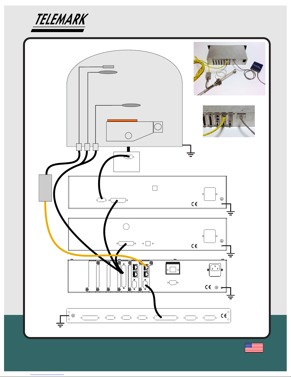
TYPICAL SYSTEM CONFIGURATION
CRYSTAL SHUTTER
SOURCE SHUTTER
Do not mix up the oscillator RJ45
cable and an Ethernet RJ45 cable
Page 2
Model 861 Quick Setup
3
1801 SE Commerce Avenue Tel 360-723-5360 [email protected]
Battle Ground, WA 98604, USA Fax 360-723-5368 www.telemark.com
MADE IN USA
1
BEFORE INSTALLING DEPOSITION CONTROLLER
The 861 can be operated with 0 to 4 I/O cards installed. There are 3 types of I/O cards:
37 pin with 8 inputs and 8 outputs plus a dedicated “abort” output (360/860 pinout)
25 pin input (880 pinout)
25 pin output.(880 pinout)
If ordered with 37 pin I/O card(s) from the factory with the proper setting then this step can
be skipped. The 37 pin I/O card has jumpers that need to be set for Active or Passive Input
operation. Passive input is TTL level inputs activated by a short across input pins. Active input is
activated by 12 to 24 volts DC across the input pins. To change setting remove the controller cover
and move jumpers on PC board.
The 25 pin input card has both Active and Passive pins available .
2
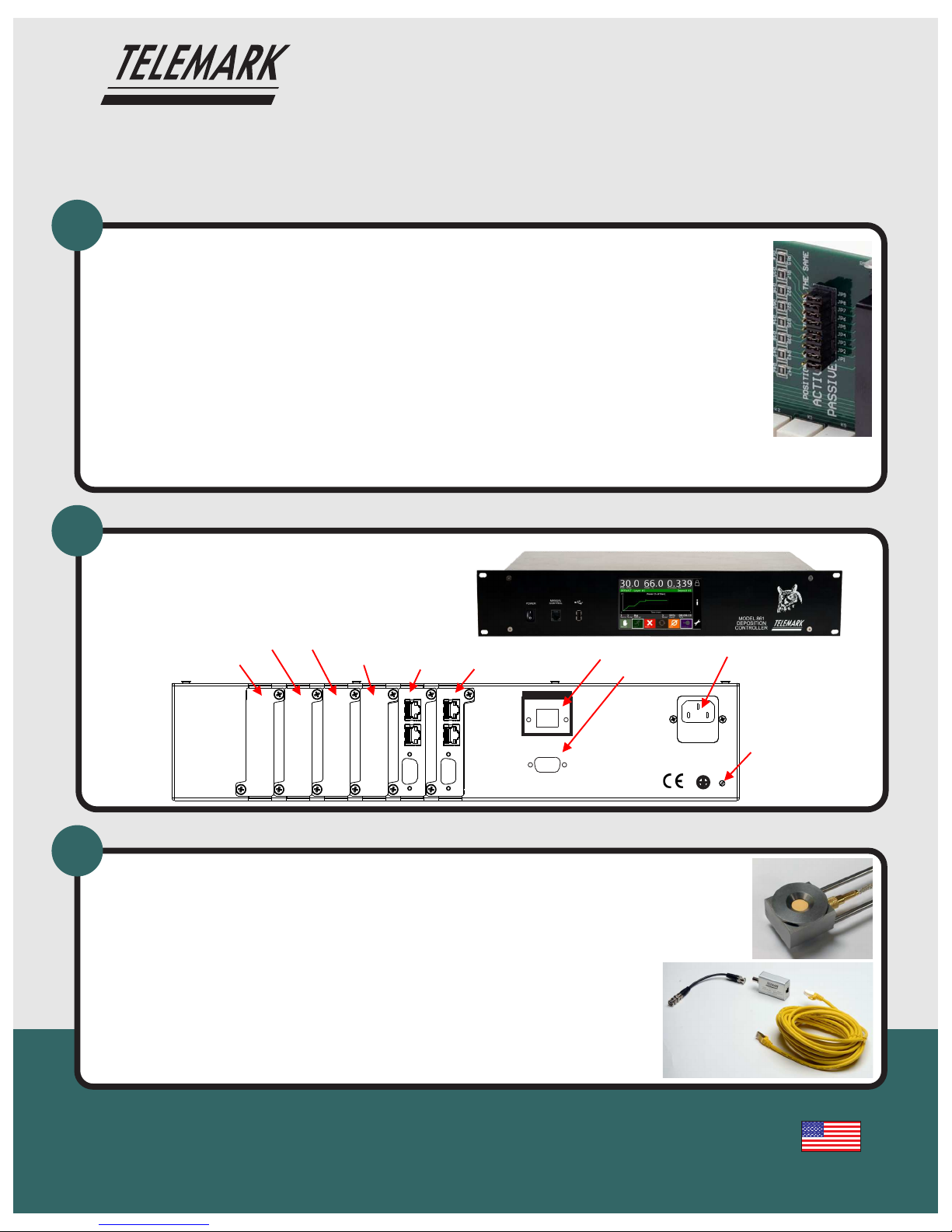
INSTALL DEPOSITION CONTROLLER
The 861 is designed to be installed in a 19 inch rack.
Required power: 90-264 VAC, 47-63 Hz
The 861should be proper grounded, see manual for
more details.
Ground
Source/
Sensor 3,4
Source/
Sensor 1,2
I/O Slot 1
Power
I/O Slot 2
I/O Slot 4
I/O Slot 3
ETHERNE T ONLY
SOURCE
POWER
115V/230V, 50/60Hz
2A SLO-BLO
I/O
1
I/O
2
I/O
3
I/O
4
13
24
1,23,4
SENSOR
SENSOR
SOURCE
CAUTIO N
RS232
Ethernet
RS-232
INSTALL CRYSTAL SENSOR AND OSCILLATOR
The 861 is designed to be used with:
- 5 or 6 MHz crystals
- Internal vacuum coaxial cable, 30 inches long (from crystal sensor to feed through)
- External BNC cable, 6 inches long (from feed through to oscillator)
- Telemark oscillator (other oscillators will not work)
- Shielded RJ45 cable, to 25 feet long (from oscillator to 861)
Oscillator
Oscillator Cable
BNC Cable
Crystal Sensor
Notes:
- The full manual is found on the included USB drive in pdf form.
- The 861 boots up to the splash screen 30 seconds, and the configuration screen in under 2 minutes.
- The 861 is shipped with crystal simulation turned off, if crystal sensor one is not connected then the
crystal error will sound when the 861 is turned on.
- The 861 is shipped with the 6MHz setting and screen saver set to 15 minutes.
Page 3
Model 861 Quick Setup
1801 SE Commerce Avenue Tel 360-723-5360 [email protected]
Battle Ground, WA 98604, USA Fax 360-723-5368 www.telemark.com
MADE IN USA
4
CONFIGURING THE 861 SYSTEM, see the 861 manual for more details
Full manual is found on the included USB drive in pdf form
1. Setup – Display: Parameters affecting the display
2. Setup – Utility: Miscellaneous parameters such as, crystal frequency, sound
volumes, date and time
3. Setup – Source: number of pockets, shutter, indexer, source voltage, etc.
4. Setup – Sensor: number of crystals, shutter, indexer, etc.
5. Setup – Inputs: Setup of user defined inputs and system defined inputs. User
defined inputs are used to trigger outputs and actions. System defined inputs are
automatically created by the 861 for source and sensor selection feedback. After
the inputs are created the D connector pins can be changed if needed.
Setup outputs and actions may need to be changed after materials and processes
are defined because they can be used in condition strings
6. Setup – Outputs: User defined outputs and system defined outputs. User
defined outputs can be triggered by condition strings. System defined outputs are
automatically created by the 861 for source and sensor selection and shutter
control. After the outputs are created the D connector pins can be changed if
needed.
7. Setup – Actions: 16 internal user programmable actions can be used to provide
special functions upon the true evaluation of a condition string. These functions
may be such things as terminating a deposit on an input from an optical monitor
or sounding an alarm when certain events are true.
DEFINE MATERIALS AND PROCESSES, see the 861 manual for more details
1. Materials: Parameters affecting the deposition of each material: density,
impedance, source#, pocket#, sensor#, etc.
2. Process: Describes the layers of a process. Once a material has been created in
the 861 then it can be added to a process layer and given a thickness. There can
be up to 99 layers per process.
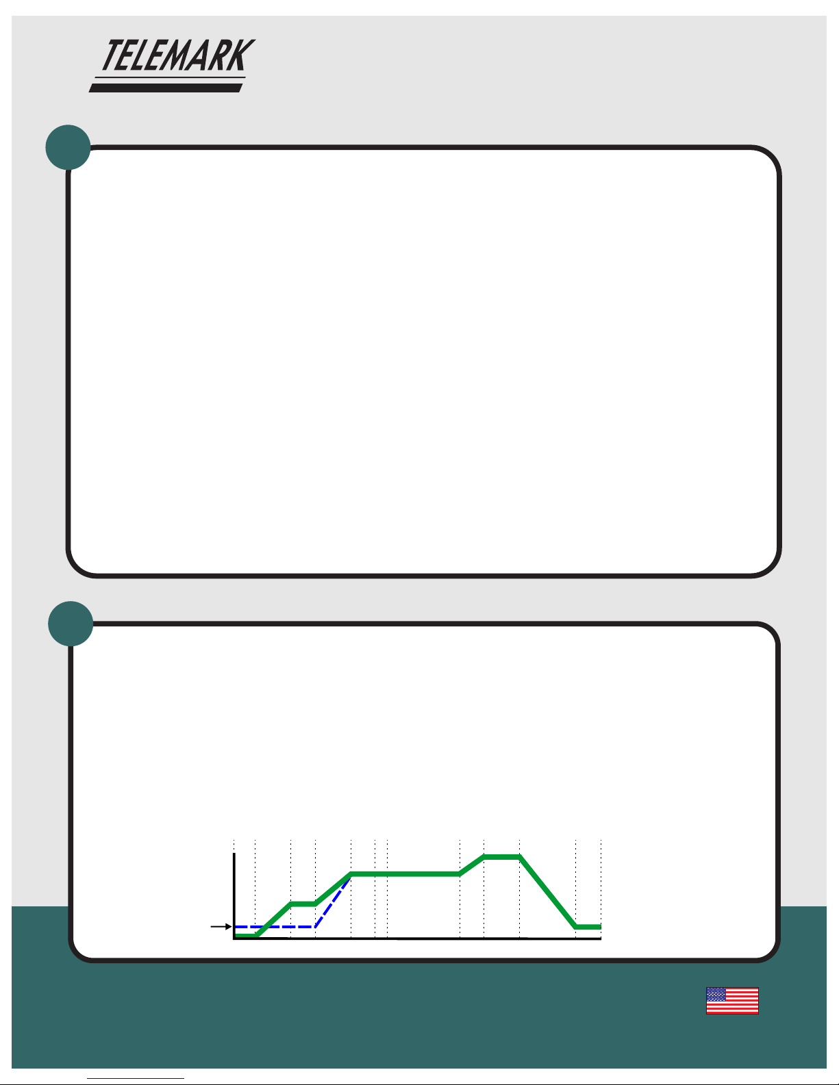
5
Typical process profile
of one layer defined by
material settings
0
100%
Power
Time
Start “Soak Rise”
Start “Soak Hold”
Start “Predeposit Rise”
Start “Predeposit Hold”
Start “Establish Rate”
Start “Deposit #1” (Open Shutter)
Start “Rate Ramp #1”
End “Rate Ramp #1”
End deposit (Close Shutter)
Start “Ramp
T
o Idle”
Start “Idle”
Idle
4 possible ramps
End Layer
Start Layer
Page 4
Model 861 Quick Setup
1801 SE Commerce Avenue Tel 360-723-5360 [email protected]
Battle Ground, WA 98604, USA Fax 360-723-5368 www.telemark.com
MADE IN USA
6
OPERATING THE 861
SYSTEM,
see chapter 6 of the 861 manual for
more details
Full manual is found on the included USB drive in pdf form
ADDITIONAL NOTES:
The USB drive supplied with the 861 is for backing up and restoring materials, processes, and all the
system files. It is also useful for data logging. It also includes a 861 pdf manual, 360/860 conversion
software and VNC software and other Telemark information.
The supplied handheld remote is for manually adjusting powerwhen in “Manual” mode and for activating “Abort” at
any time.
The 861 can be viewed and controlled remotely via Ethernet and a VNC client (Remote Desktop),see chapter 4.
The network needs to have a DHCP server to automatically supply the 861 with an IP address.
See chapter 7 to see the how to tune the material control loop parameters referred to as PID parameters
(Proportional gain, Integral Time constant and Derivative Time constant).
See chapter 8 for details about control of an 861 from computer/PLC using the RS-232 serial interface. The
interface is set at 9600 Baud, 8 Bit data, No Parity, 1 Stop bit
7
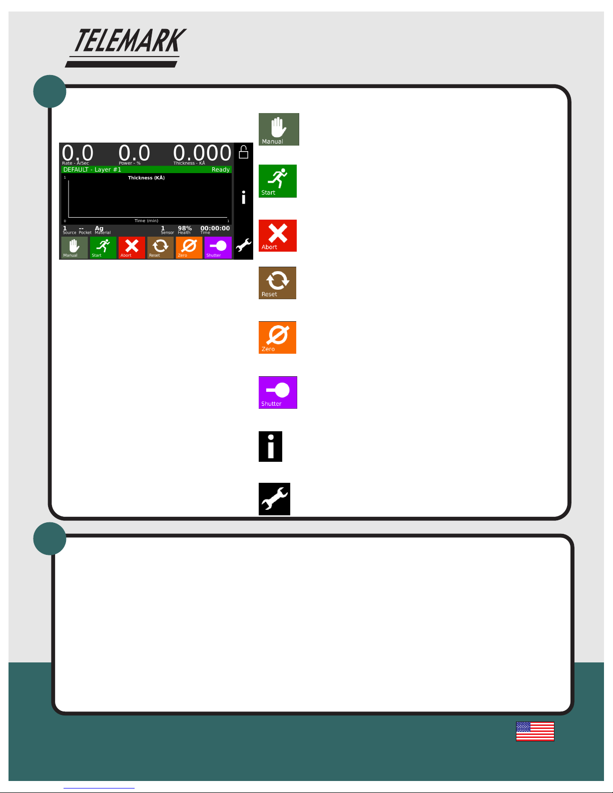
MANUAL BUTTON
This button is used to toggle the 861 Manual mode on and off. The Manual mode
indicates that the source control voltage output is being controlled through the
Remote Power Handset
START BUTTON
The Start button starts a process, starts a layer, resumes an aborted process, or
notifies the 861 that the pocket or crystal is in position.
ABORT BUTTON
The Abort button puts the 861 into the Abort mode.
RESET BUTTON
The Reset button is used to clear the controller from Abort mode and put it into the
Ready mode.
ZERO BUTTON
Pressing the Zero button causes the thickness display to go to zero. This button is
active at all times
SHUTTER BUTTON
This button is used to manually open and close the active source shutter.
STATUS BUTTON
This button is used to cycle through the different status screens. The display settings
allow the six different status screens to be active or not. Refer to chapter 6 for a detailed
description of these status screens.
PROGRAM BUTTON
Pressing the programming button will bring up the main programming screen.
 Loading...