

Page 1

DTR4000CA
User Manual
Satellite Solutions
Copyright© 1999 GLOBAL TELEMANN SYSTEMS Inc.
All rights reserved.
This manual is subject to change without prior notice.
GLOBAL TELEMANN SYSTEMS Inc.
TEL:+1 408 955 7750 / FAX:+1 408 955 7740
2345 Harris Way, Suite 100,
San Jose, CA95131, USA
E-mail : [email protected]
WWW : http://www.telemann.com
Page 2

DTR4000CA Safety Precautions
Table of Contents
INTRODUCTION.................................................................................................................................................6
A
BOUT THIS MANUAL..........................................................................................................................................6
G
ENERAL DESCRIPTION........................................................................................................................................6
G
ENERAL FEATURES.............................................................................................................................................6
HARDWARE DES CRIPTION.............................................................................................................................7
F
RONT PANEL CONFIGURA TI ON............................................................................................................................7
R
EAR PANEL CONFIGURATION .............................................................................................................................9
H
OW TO CONNECT YOUR DTR4000CA TO VARIOUS SYSTEMS ......................................................................... 10
REMOTE CONTROL........................................................................................................................................12
R
EMOTE CONTROL UNIT....................................................................................................................................12
SYSTEM SET-UP................................................................................................................................................ 14
B
ASIC MENU OPERATION ...................................................................................................................................14
F
LOW OF MENU SYSTEM....................................................................................................................................15
A
UTOMATIC CHANNEL SET-UP...........................................................................................................................17
Automatic channel set-up for a satellite........................................................................................................17
Automatic channel set-up for a transponder.................................................................................................17
MENU OPERATION..........................................................................................................................................18
M
AIN MENU.......................................................................................................................................................18
C
HANNEL GUIDE................................................................................................................................................18
TV and Radio Channel Guide........................................................................................................................ 18
C
HANNEL LIST ...................................................................................................................................................19
TV and Radio Channel List ...........................................................................................................................19
P
ARENTAL CONTROL..........................................................................................................................................19
PIN Code / TV and Radio Lock .....................................................................................................................19
I
NSTALL ATION .................................................................................................................................................... 20
PIN Code ?....................................................................................................................................................20
LNB Configuration........................................................................................................................................21
Channel Search............................................................................................................................................. 22
Edit Channels................................................................................................................................................23
Edit TV Channel..........................................................................................................................................................23
Edit Radio Channel......................................................................................................................................................24
Add to Favorite............................................................................................................. E rror! Boo k ma r k not defined.
Edit Favorite Channel...................................................................................................Error! Bookmar k not def i ne d.
System Settings.................................................................................................Error! Bookmark not defined.
Change PIN......................................................................................................Error! Bookmark not defined.
PIN Code......................................................................................................................Error! B oo k mar k not def i ned.
Receiver Update...............................................................................................Error! Bookmark not defined.
Auto Installation...............................................................................................Error! Bookmark not defined.
A
CCESSGATE................................................................................................ERROR! BOOKMARK NOT DEFINED.
Entitlement........................................................................................................Error! Bookmark not defined.
Group Entitlement........................................................................................................Error! Boo k ma r k not defined.
Channel Entitlement .....................................................................................................Error! Book mar k not def i ne d.
Remainder Token List...................................................................................................Er ror! B oo k mar k not def i ne d.
Usage-record....................................................................................................Error! Bookmark not defined.
Amount of record.........................................................................................................Error! Bookmar k not def i ne d.
List of Record...............................................................................................................Error! Book mar k not def i ne d.
Modify Smart Card PIN....................................................................................Error! Bookmark not defined.
TROUBLE SHOOTING...................................................................... ERROR! BOOKMARK NOT DEFINED.
OSD D
ISPLAY MESSAGE..............................................................................ERROR! BOOKMARK NOT DEFINED.
F
RONT PANEL DISPLAY MESSAGE................................................................ERROR! BOOKMARK NOT DEFINED.
TECHNICAL SPECIFICATIONS......................................................ERROR! BOOKM ARK NOT DE FINED.
FACTORY DEFAULT SATELLITE INFORMATION.................... ERROR! BOOKMARK NOT DEFINED.
Page 3

DTR4000CA Safety Precautions
Page 4

DTR4000CA Safety Precautions
RADIO FREQUCNCY INTERFERENCE STA TEMENT
Note : This equipment has been tested and found to comply with the limits for a Class B
Digital device, pursuant to part 15, Subpart B of the FCC Rules. This equipment generates,
Uses, and can radiate radio frequency energy. If not installed and used in accordance with
The instructions, it may cause interference to radio communications.
The limits are designed to provide reasonable protection against such interference in a
Residential situation. However, there is no guarantee that interference will not occur in a
Particular installation. If this equipment does cause interference to radio or television
Reception, which can be determined by turning the equipment on and off, the user is
Encouraged to try to correct the interference by one or more of the following measures:
Reorient or relocate the receiving antenna of the
affected radio or television.
Increase the separation between the equipment and
the affected receiver.
Connect the equipment and the affected receiver to
power outlets on separate circuits.
Consult the dealer or an experienced radio/TV
technician for help.
Page 5

DTR4000CA Safety Precautions
SAFETEY PRECAUTIONS
This IRD has been manufactured to meet international safety standards.
Please read carefully the following safety precautions before you handle the IRD.
MAINS SUPPLY
LOCATION
CLEANING
OVERLOADING
VENTILATION
LIQUIDS
SAMILL OBJECTD
ATT ACHMENTS
CONDITIONAL ACCESS
(CAM) and/or COMMON
INTERFACE MODULE
CONNECTION TO THE
SATELLITE DISH LNB
EARTHING
LIGHTNING
SERVICING
Use only 85-265V AC 50/60Hz.
Locate the IRD indoor place properly to prevent any hazards or
malfunctions from lightening, raining and direct sunlight.
1. Disconnect the IRD power cord from the wall socket before
cleaning it.
2. Use a cloth lightly dampened with water (no solvents) to clean
the exterior of the IRD.
Do not overload wall outlets, extension cords or adapters. These
can cause fire or electrical shock.
1. Do not block the decoder’s ventilation slots.
2. Ensure that a free airflow is maintained around the IRD.
3. NEVER stand the IRD on soft furnishings or carpets.
4. Do not use or store the IRD where it is exposed to direct
sunlight or near a heater. NEVER stack other electronic
equipment on top of the IRD.
Keep liquids away from the IRD.
Coins or other small objects must be kept away from the IRD. They
can fall through the ventilation slots of the IRD and cause serious
damage.
Do not use any attachments that are not recommended.
These may cause hazards or damage the equipment.
Main power cord must be disconnected before inserting or
removing the CA Module and/or CI Module
Before connecting or disconnecting the cable from the satellite dish
to the IRD, disconnect the IRD from the main power.
FAILURE TO DO SO CAN DAMAGE THE LNB.
The LNB cable MUST BE EARTHED to the system earth for the
satellite dish.
The earthling system must comply with SABS 061.
1. It is recommended that the IRD should remain connected at all
times to the main power supply and satellite dish (except when
working on the LNB).
2. However, the Manufacturer’s instructions for safeguarding
other equipment connected to the IRD, i,e, TV set, etc., must
be followed during lightning storms.
3. Lightning protection devices for the terrestrial antenna, mains,
LNB and the modem telephone line, are essential.
1. Do not attempt to service this product yourself.
2. Refer all servicing to qualified service agents.
Page 6

Introduction
About This Manual
This manual describes how to install and operate the Model DTR4000CA. Only
qualified personnel should handle any problems beyond this manual.
General Description
The DTR4000CA is a high-performance IRD (Integrated Receiver Decoder).
DTR4000CA is fully compliant with the MPEG2 based DVB transmission
standards for in-home reception of satellite digital broadcast services such as digital
TVs and radio channels
DTR4000CA Introduction
.
General Features
Features equipped in DTR 4000CA are as follows :
Fully compliant with MPEG2 based DVB transmission standards
Fully Universal Tuner with 950-2150MHz
QPSK Demodulator
Extended Symbol Rate (2-45MS/s)
SCPC and MCPC, C-/Ku-bands
Automatic Detection of Video Polarity
Automatic Detection of Forward Error Correction
Automatic Channel Surfing Function
Automatic NTSC/PAL Detection
Simple Video Converter (NTSC PAL)
Lip-sync Error Correction Function
Wide PLL Modulator (CH21-69, PAL-B, G, I, D, K)
Useful High Speed System Port for System Diagnostic and Upgrade
DiSEqC1.0 LNB Control Software
TV/VCR scart connectors
Teletext : CCIR/ITU-R Broadcast Teletext System B
Smart Card interface for CAS
Simultaneous decoding of up to Max. 32 PIDs with the exception of A/V
Internal Modem (Optional)
User-friendly defined On-screen-display (OSD)
Page 7
DTR4000CA Hardware Description
Hardware description
Here, you will be given the explanation of the front and rear panel of DTR4000CA. Each of
display, ports, connections will be explained.
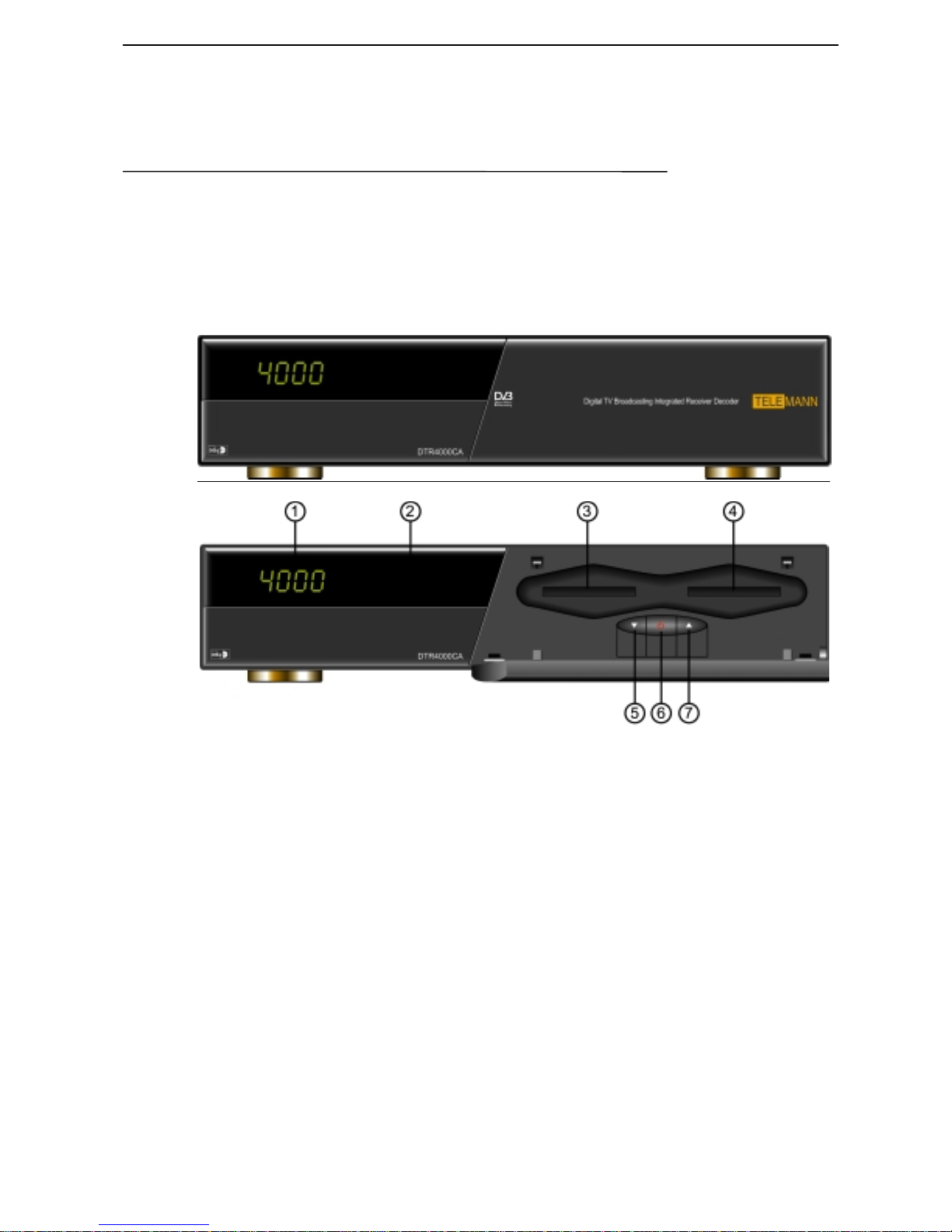
Front Panel Configuration
1 LED DISPLAY
This shows the channel number or other information as follows :
During power is off, the dash ‘-‘ will be displayed at each digit, which
indicates that your DTR4000CA is in stand-by mode. Immediately after your
decoder turns on, ‘C . . .’ will light up at each digit, which means that your
DTR4000CA is ready to operate.
If your DTR4000CA locks a channel, its channel number will be displayed.
Whenever you change the channel, the number of the changed channel will be
displayed.
2 REMOTE SENSOR
It receives the infrared signal from Remote Control and operates your
DTR4000CA.
3
Smart Card and/or PCMCIA Card Slot (Option), or Not Used
These two slots can be used either for Conditional Access System with Smart
card, or Common Interface Module with PCMCIA card, or may not be used at
all in case of free-to-air only set-top-box according to the option configuration
Page 8

DTR4000CA Hardware Description
of the DTR5000N.
When you want to watch Pay-per-view TV program or enjoy Internet service
on a usage basis, you should purchase a smart card or PCMCIA card from the
service provider and insert it into this slot. The detailed usage explanation will
come with the card that you purchased.
5 CHANNEL DOWN
You can sequentially select the previous service by pressing this DOWN key.
6 POWER
This key allows you to turn your DTR4000CA on or off.
7 CHANNEL UP
You can use this key to select the next channel sequentially.
Page 9
DTR4000CA Hardware Description
Rear Panel Configuration
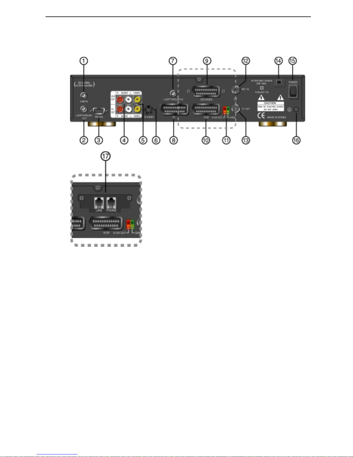
The following diagram shows the DTR4000CA with analog board. Here the dotted line can be
replaced with the Modem board (option) below.
1 LNB IN
Satellite antenna input terminal. The LNB power (14/18V) and the switching
signals (22KHz/DiSEqC) are also supplied to LNB through this terminal.
2 LNB OUT
It is for connecting another STB to your DTR4000CA. Connect this terminal
to LNB IN terminal of the other STB via RF cable.
3 RS-232 serial port
An operator for customer services can use this port for the transmission of the
preprogrammed channel information from a PC to the DTR4000CA. Or this
port can also be used for main board testing and software upgrading.
4 AUDIO L/R output terminals
Connect these terminals to audio L/R input terminals of TV, VCR, or Hi-Fi
audio system.
5 VIDEO output terminal
Connect this terminal to video input terminal of TV or VCR.
6 S-VIDEO output terminal
Page 10

DTR4000CA Hardware Description
This terminal is connected to S-VIDEO input terminal of TV or VCR to output
S-VIDEO signal.
7 TV SCART connector
Connect this connector to that of TV via a SCART cable.
8 Modem Port (Option)
When you use Conditional Access System, you should use modem to send
your usage information to the operator.
9 VCR SCART connector
Connect this connector to that of VCR via a SCART cable.
10 0/12V OUT
Connect this terminal to an external 0/12Volt switch box.
11 ANT IN
Connect this terminal to a terrestrial UHF antenna via coaxial cable.
12 TV OUT
Connect this terminal to the input of TV or VCR via a coaxial cable.
13 POWER INPUT
Connect the power cord of AC85V to 265V, 50/60Hz
14 Ground
How to Connect Your DTR4000CA to Various Systems
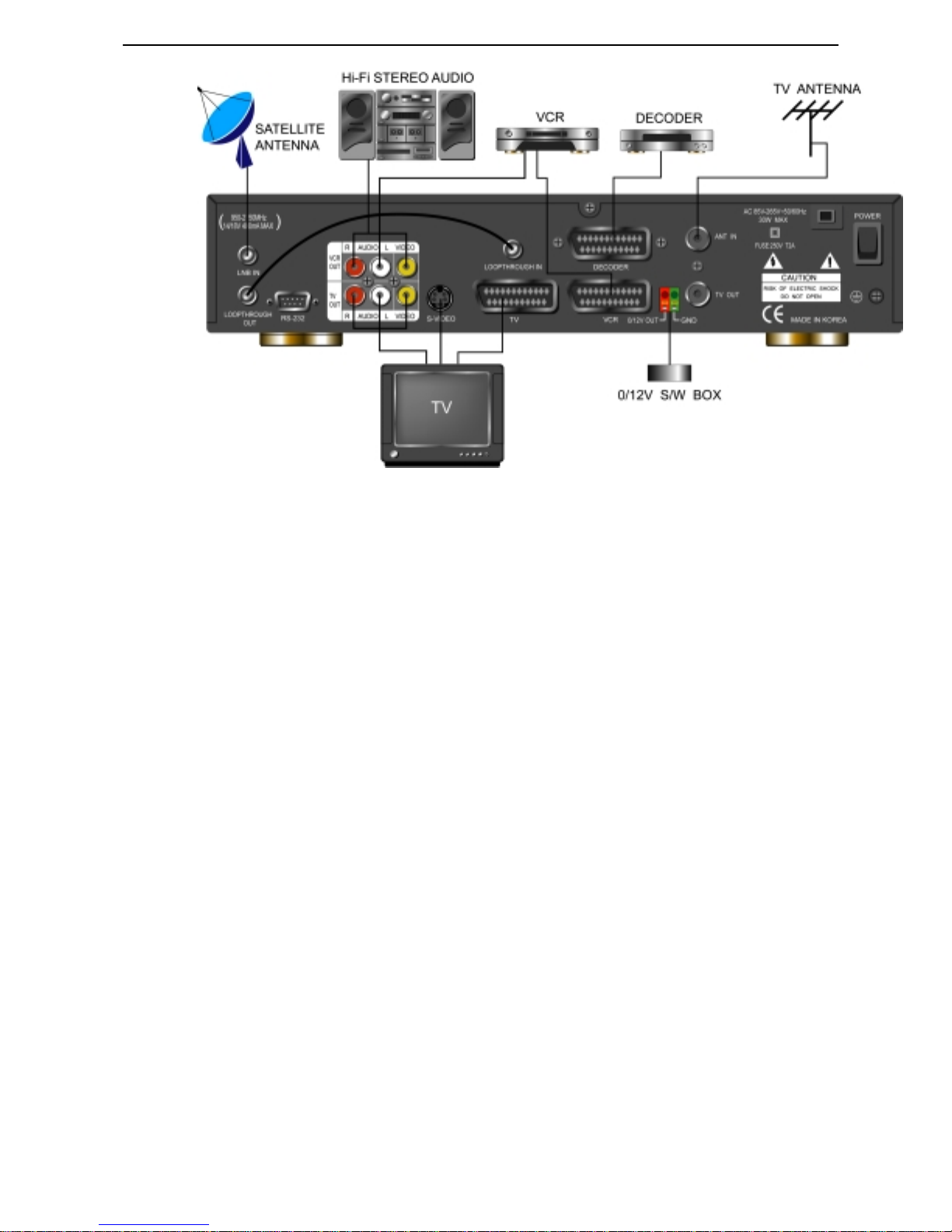
As shown in the figure below, you can connect your DTR4000CA to a TV set, a
VCR and a Hi Fi system. Consult your local supplier for assistance in setting-up
your system best suited to your requirements.
CAUTION !
Please DO NOT plug in the main power supply cord until you have
finished all other connection!
Page 11
DTR4000CA Hardware Description
Connection of your DTR4000CA to a TV set
Connect your DTR4000CA to a TV set with SCART.
Connection of your DTR4000CA to a VCR
Connect the SCART connector of VCR to that on your DTR4000CA.
Connection of your DTR4000CA to a Hi Fi system
Connect a RCA/Cinch stereo cable from the AUDIO L/R terminals on your
DTR4000CA to the LINE, AUX, SPARE or EXTRA input terminals on your Hi Fi
system.
Connection of the analog decoder SCART to outside scramble decoder
When you watch scrambled analog video, you should connect the analog SCART to
outside scramble decoder.
Page 12
DTR4000CA Remote Control
Remote Control
Remote Control Unit
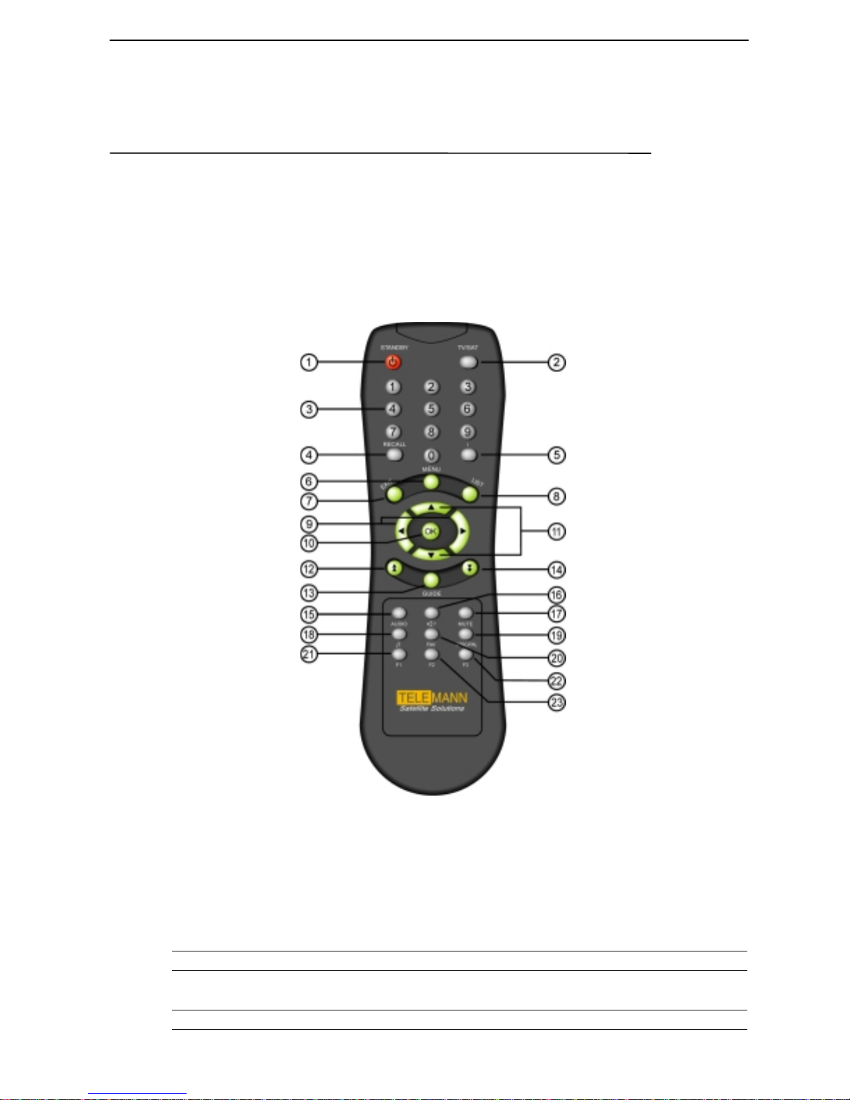
This section describes how to operate the DTR4000CA using the buttons on your
Remote Control Unit as shown below.
(1) POWER
(2) TV/SAT
(3) Num ber
To turn your DTR4000CA on/off.
To toggle from TV mode to satellite broadcasting mode
and vice versa
To select channel number or input parameters on menu.
Page 13

DTR4000CA Remote Control
(4) RECALL
(5) i
(6) MENU
To return back to the previous channel.
To display the program information on the screen
To display the main menu on the screen. Or to move back
to previous menu from current menu.
(7) EXIT
(8) LIST
(9) VOL UP/DN
(10) OK
(11) CH UP/DN
(12) Page UP
(13) GUIDE
(14) Page DOWN
(15) AUDIO
(16) Language( ? )
(17) MUTE
(18)
(19) NTSC/PAL
(20) FAV
To get completely out of menu.
To list all channels available on the screen
To increase/decrease the volume or select item on menu
To confirm your choices
To select a channel
To step pages up in the channel list
Program Guide on the screen
To step pages down in the channel list
To select Audio mode
To select the desired language or Audio PID.
To turn the sound on/off
To select TV and Radio
To convert video mode (NTSC/PAL/AUTO).
To display Favorite channel list on the screen
(21) F1 Function Key 1 ( Add channel )
(22) F2 Function Key 2
(23) F3 Function Key 3 ( Delete Channel )
Page 14
System Set-up
Here, we will go through the menu system. To manipulate the menu, you use mainly
the following key strokes : UP/DOWN, Left / Right, OK Menu, Exit
Basic Menu Operation
To maneuver the Menu, you can use the following keys
UP/DOWN key (▲ ▼) Moves menu selection up and down
Left / Right key () Can change option values
Page Up/Down ( ) Move up/down by page ( 6 channels)
OK Key ( OK ) Selects menus or You can move directly to a certain
Menu key Displays main Menu or goes to previous menu
Numeric Key Enters numbers. Or Selects a certain channel by pressing
Exit key Quits the whole Menu
F1, F2, F3 Function Keys. The function varies depending on each
DTR4000CA System Set-up
channel by pressing the channel number.
the channel number.
menu
Page 15
Flow of Menu System
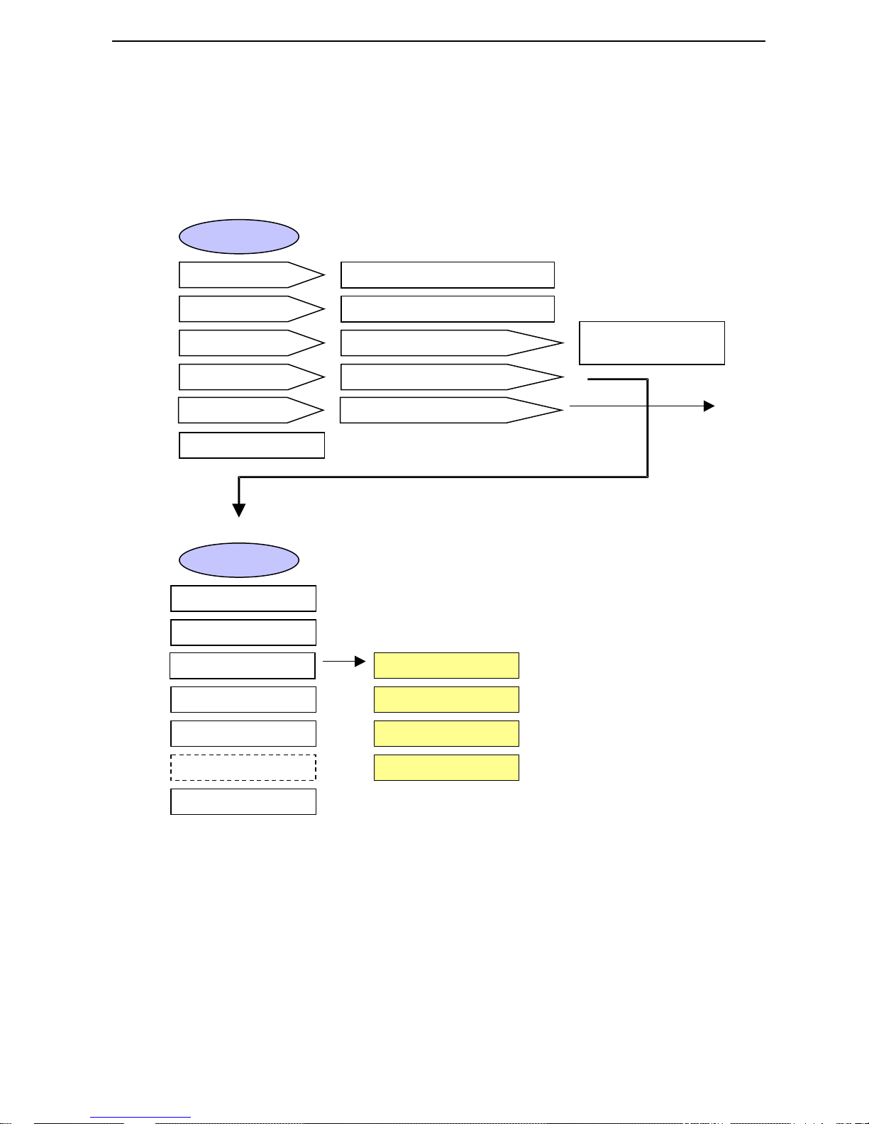
Here, the following diagram shows the hierarchy of menu system.
For detailed explanation of each menu, refer to the following Menu explanation.
Main Menu
DTR4000CA System Set-up
TV/Radio Channel GuideChannel Guide
Channel List
Parental Control
Installation
AccessGate
About DTR4000CA
Installation
LNB Configuration
Channel Search
Edit Channels
System Settings
TV/Radio Channel List
PIN Code ?
PIN Code ?
Smart Card PIN Code ?
Edit TV Channel
Edit Radio Channel
TV, Radio
Parental Lock
See next page
Change PIN
Receiver Upgrade
Auto Installation
Add to Favorites
Edit Favorite Channel
Page 16
AccessGate
DTR4000CA System Set-up
Edit Channels
Usage-record
Modify Smart Card PIN
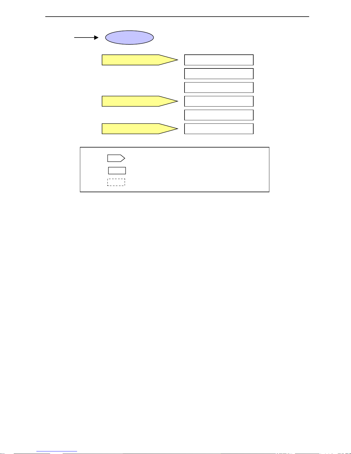
This Menu has several submenus
This menu has a final setting menu
This menu will be added later
Fig 5. Flow chart of menu system
Group Entitlement
Channel Entitlement
Remainder Token List
Amount of Record
List of Record
Change PIN
Page 17
DTR4000CA System Set-up
Automatic Channel Set-up
Automatic channel set-up f or a satellite
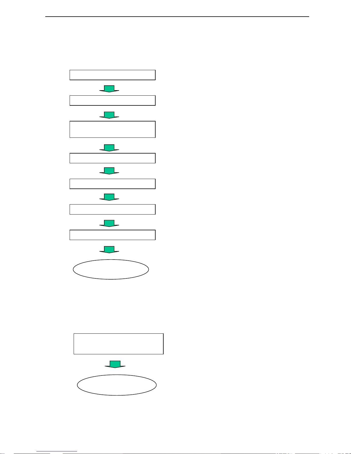
You can automatically detect and save all TV and Radio channels for a Satellite
As follows.
System Connection
Power on
Main Menu/Installation/
LNB Configuration
LNB Configuration Setting
and then LNB configuration
Save changes by pressing O.K button.
Connect DTR4000CA with all peripheral devices.
Turn on the power of DTR4000CA and other devices.
Move to the menu of Installation,
Insert all LNB information of your Antenna.
Auto Installation
Channel List
Favorite Channel List
DTR4000CA will automatically searches and saves into
channel list all TV and Radio channels from a satellite.
If you push List button of the remote controll,
you should see all channel lists that you saved.
Move to Menu/Installation/Edit Channels/Add to Favorite
Choose Favorite Group on the right side of the screen.
Press F1 to transfer the selected channel from the channel
list to Favorite Channel List.
Press List to see
the channel list
Automatic channel set-up for a transponder
You can automatically detect and save all TV and Radio channels for a transponder
as follows.
Main Menu/Installation/
Channel Search
At Channel Search Menu, enter all the Transponder
information of a transponder.
Press O.K. The DTR4000CA will automatically
find channel information for that transponder.
Press List to see
the channel list
Page 18
DTR4000CA Factory Default Satellite Information
Menu Operation
Main Menu
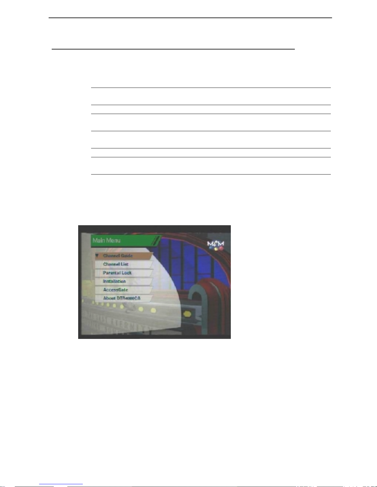
Main menu shows the following information.
Channel Guide Shows general information about each channel such as
Channel Name, LNB Number, PID Number.
Channel List Shows the whole channel list registered in DTR4000CA
Parental Control Allows only those people with knowledge of the PIN
code to watch the programs.
Installation Allows you to set various parameters on LNB
configuration, System Settings, and etc.
AccessGate Shows information about AccessGate system.
About DTR4000CA Shows the version information of DTR4000CA
software
Turn on TV and your DTR4000CA after you have connected all peripheral
devices to it.
Press the Menu button of the remote control. You will get the Main Menu on
the TV screen as follows.
You can move into submenus by selecting each menu.
Press the Menu button to return to previous menu. Or press Exit to quit the
Menu system completely.
Channel Guide
TV and Radio Channel Guide
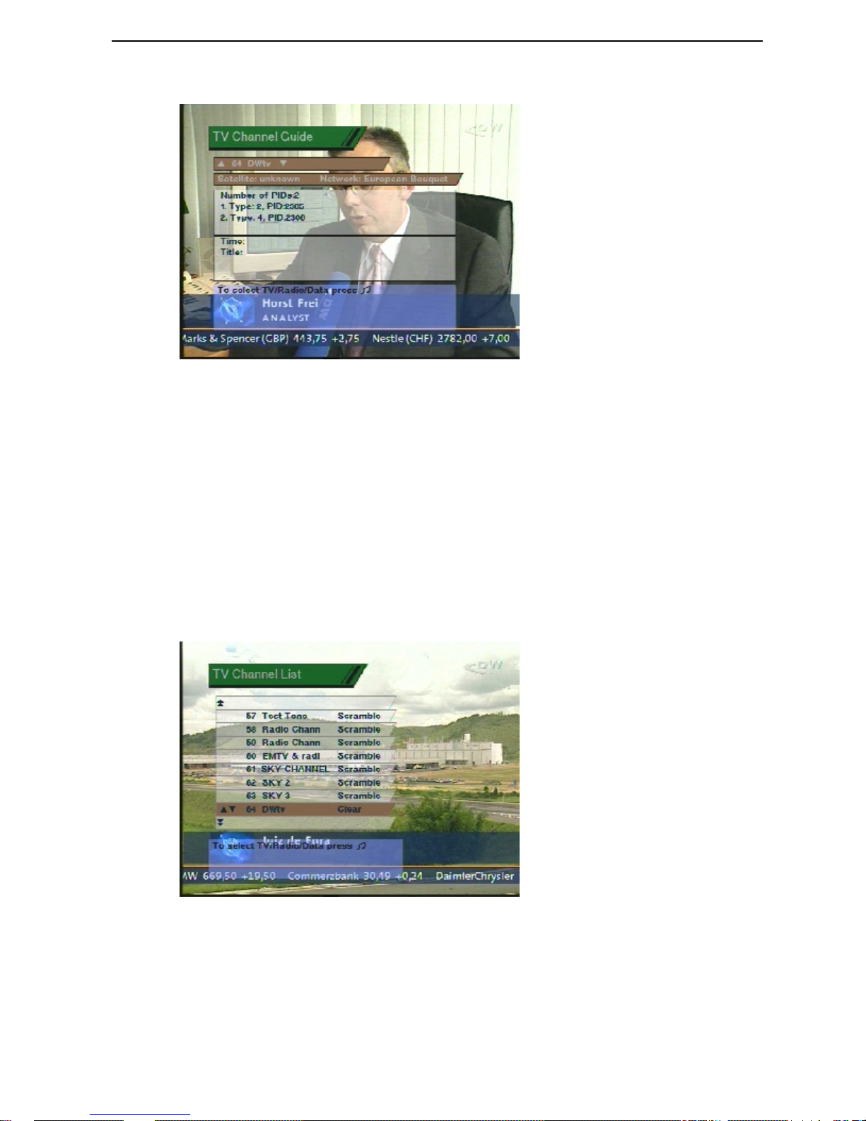
Here you can see the information about Channel Name and Number, Number of
PIDs, and PID Types.
In Main Menu, select Channel Guide. Then you will see TV Guide display as
follows. You can change the channel by pushing the Up/Down keys.
When you push “” on the Remote Control, you can select TV or Radio
Page 19
DTR4000CA Factory Default Satellite Information
Guide.
Channel List
TV and Radio Channel List
This menu helps you easily select the channel that you want to watch.
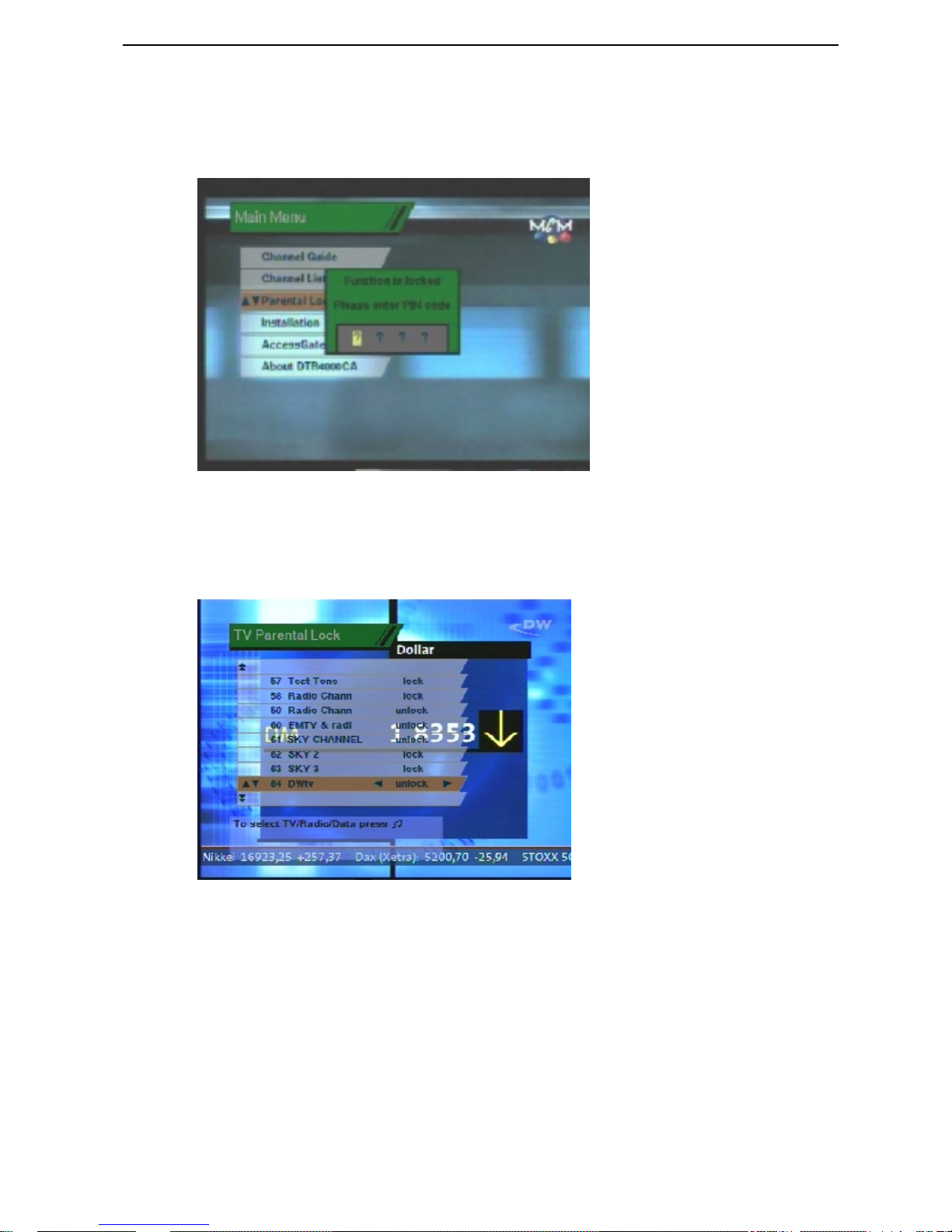
In Main Menu, select Channel List. Then you will see TV Channels display as
follows. You can get the information of Channel Number, Channel Name, and
whether the program Scrambled or Clear.
To watch a specific channel, first select a certain channel by pushing the
Up/Down key, Page Up/Down key. Then, hit the OK button on the Remote
Control. This enables you to move into that specific channel.
When you push “” on the Remote Control, you can select TV and Radio
Guide.
Parental Control
PIN Code / TV and Radio Lock
This function prevents children or unauthorized persons from watching programs.
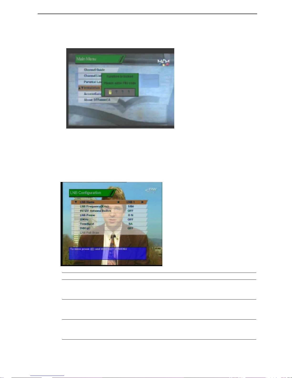
Select the Parental Control on the Main Menu. Then you will be asked to enter
Page 20
DTR4000CA Factory Default Satellite Information
PID number. The PIN code is four digit numbers. Factory default value is 0000.
Press UP/DOWN key to highlight the program you want, then press OK to
have the channel locked so that others who do not know the PID can not watch
the program.
Once the program is locked, every time you try to watch the program, you will
be asked to enter PIN code.
When you push “” on the Remote Control, you can select either TV or Radio
Guide.
Press the Menu button to return to previous menu. Or press Exit to get out of
Menu completely.
Installation
Installation Menu helps you setup the system and manage channel information.
PIN Code ?
Select the Installation menu from the Main menu. You will then be asked to
enter your PIN.
Page 21
DTR4000CA Factory Default Satellite Information
Enter your PIN, then press OK to confirm it. Then submenus will appear, which
allows you to change the preferences that were set factory default values. You
can also add features to the existing selections.
LNB Configuration
LNB Configuration helps you enter information of LNB that is connected to
DTR4000CA
In Installation menu, select LNB Configuration. Then the following screen
pops up
LNB Names Selects one LNB out of eight LNBs
LNB Frequency(KHz) Either you can select predefined LNB Frequency by
Left/Right keys or manually enter a specific
frequency in KHz unit.
0V/12V Antenna Switch Depending on the use’s antenna switch box, you can
pick up either 12V by setting “On” or 0V by setting
“off”
LNB Power Depending on the use’s antenna LNB, you can supply
either LNB power by setting “On” or not by setting
“off”
Page 22

DTR4000CA Factory Default Satellite Information
22KHz Depending on the use’s antenna switch box or LNB,
you can supply either 22KHz by setting “On” or off
by setting “off”
Tone Burst Depending on the user’s antenna switch box, you can
pick up either A by setting “SA”, B by setting “SB”,
or “Off”.
DiSEqC If you have DiSEqC box(es), you can choose port one
to four by selecting port number one to four. Or if you
do not have DiSEqC box, choose “off”
* This setting should be done for all the LNBs that you want to connect to by
changing the LNB name.
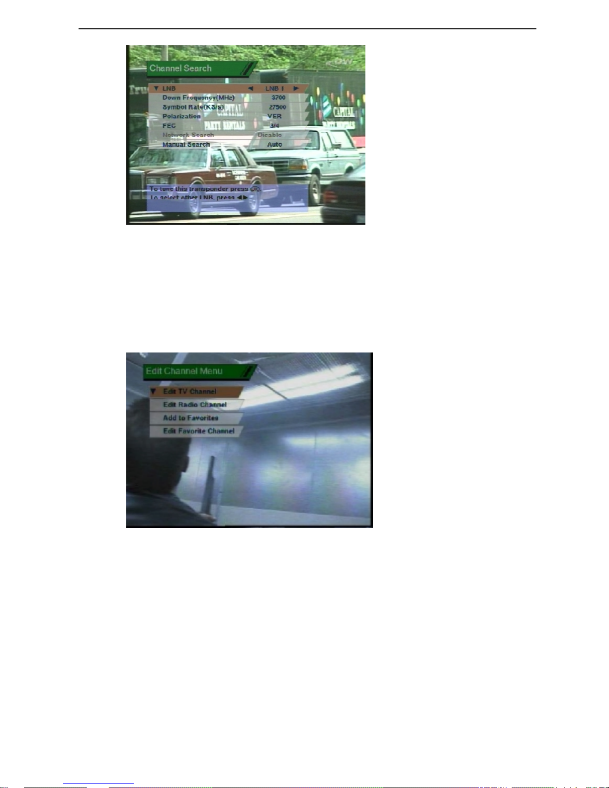
Channel Search
Channel Search helps you catch the channel information of each transponder.
In Installation menu, select Channel Search menu. Then the Channel Search
screen pops up
LNB From LNBs that you set up in LNB Setup menu, select
one LNB.
Down Frequency(MHz) Enter the transponder frequency of the satellite that you
choose by setting LNB parameters.
Symbol Rate(KS/s) Enter the symbol rate of the above-mentioned
transponder or set up “Auto” if you do not know the
symbol rate. In latter case, it will take time.
Polarization Choose the Polarization of the above-mentioned
transponder. Select “VER” if the polarization is vertical,
or “HOR” if it is horizontal. if you do not know the
Polarization, select “Auto”. In latter case, it will take
time.
FEC(Forward Error
Correction)
Choose FEC of the above-mentioned transponder. – 1/2,
2/3, 3/4, 5/6, 7/8. If you do not know the value, choose
“Auto”.
Manual Search If the channel information that you are looking for is not
included in the SI Information that comes from the
satellite, user can manually enter those information.
In Auto mode, you can automatically search channel
information that comes from satellite. If you want to
manually enter TV channel, select “TV”. Then you
should enter those PIDs of Video, Audio, and PCR. In
case of Radio, enter the PIDs of Audio and PCR.
Page 23
DTR4000CA Factory Default Satellite Information
Edit Channels
User can manage Channels stored in DTR4000CA – Delete, Add programs to
Favorite Channels.
In Installation Menu, select Edit Channel menu. Then the following Edit
Channel Menu screen will display.
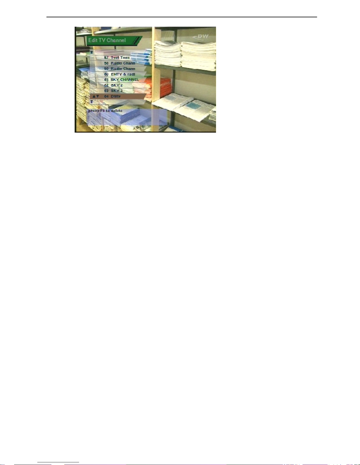
Edit TV Channel
You can delete the unnecessary TV Channels from the registry of DTR4000CA.
In Edit Channel menu, select Edit TV Channel menu. Then the following
screen pops up
Page 24
DTR4000CA Factory Default Satellite Information
From the channel list on the screen, you select the channel that you do not want
to watch. Then click “F3” button twice. The channel disappears from the
DTR4000CA program list.
Edit Radio Channel
 Loading...