

Page 1

TABLE OF CONTENTS
TABLE OF CONTENTS-------------------------------------------------- I
TABLE OF EXAMPLES------------------------------------------------IV
TABLE OF FIGURES---------------------------------------------------- V
WARRANTY------------------------------------------------------------- VII
CHAPTER ONE------------------------------------------------------------1
G
ETTING STARTED -----------------------------------------------------------1
H
OW TO USE THIS USER GUIDE -------------------------------------------1
I
NTRODUCTION----------------------------------------------------------------1
Overview ---------------------------------------------------------------- 2
Keypad------------------------------------------------------------------- 2
Printer -------------------------------------------------------------------3
Start-up (or Reset) Report--------------------------------------------- 3
Audit Trail--------------------------------------------------------------- 4
Setting the Mode-------------------------------------------------------- 4
E
VERYDAY USE---------------------------------------------------------------5
System Status Check --------------------------------------------------- 5
Management Access --------------------------------------------------- 6
Error Keys (Cancel and Delete)-------------------------------------- 7
Setting the Time -------------------------------------------------------- 8
Setting the Date and Day---------------------------------------------- 9
CHAPTER TWO --------------------------------------------------------- 10
R
EFERENCE------------------------------------------------------------------ 10
R
EPORTS --------------------------------------------------------------------- 10
Activity Reports------------------------------------------------------- 10
Activity Report Clear ------------------------------------------------ 12
P
ROGRAMS ------------------------------------------------------------------ 13
Program 1 - Fixed Rates -------------------------------------------- 14
Program 2 - Grace Periods and Threshold Billing-------------- 16
Program 3 - Cost Adjustments-------------------------------------- 18
Program 4 - Mark-Ups ---------------------------------------------- 19
Program 5 - Surcharges--------------------------------------------- 20
INN-FORM XL BASIC i
Page 2

Program 6 - Print No Charge Calls (Yes/No) -------------------- 22
Program 7 - Print Audit Trail -------------------------------------- 22
Program 8 - Store No Charge Calls ------------------------------- 23
Program 9 - Send Administrative Calls --------------------------- 23
Program 10 - Programmable Parameters Report --------------- 23
Program 11 - Set Default Programmable Parameters for
Program 1 through Program 9-------------------------------- 24
Program 12 - Set Default Programmable Parameters for
Everything that is not Set by Program 11-------------------- 25
Program 14 - Set Top of Page-------------------------------------- 27
Program 20 - Print Status of Program 21 through Program 2927
Program 21 - Add/Change Administrative Extensions ---------- 28
Program 22 - New Interim Area Code----------------------------- 30
Program 23 - Add Exchange On Site------------------------------ 31
Program 24 - Program Trunk/Access Code On Site------------- 32
Program 26 - Lines/Page, Lines to Tear Off, SMDR/Remote
Port Baud Rate and AM/PM vs. Military Time-------------- 34
Program 27 - The Universal Number Loop----------------------- 38
Program 28 - Automatic Printing and Clearing ----------------- 38
Program 30 - Download New Tariff Data Chip------------------ 38
Program 32 - Print List of Changeable SMDR
Parameters and Ruler Line ------------------------------------ 40
Program 33 - Set SMDR Related Parameters ------------------- 41
Program 248 – Restore System Settings From Flash Data Chip.44
Program 842 – Program Current System Settings to
Flash Data Chip------------------------------------------------- 45
Program 1739 - Erase Call Record Memory --------------------- 46
A
LARMS ---------------------------------------------------------------------- 47
General Information About Alarms-------------------------------- 47
911 and 311 Alarms-------------------------------------------------- 47
Printer Alarm (Power, Paper, Ribbon, Off-line)----------------- 47
INN-FORM XL Power Alarm--------------------------------------- 49
SMDR DATA---------------------------------------------------------- 49
APPENDICES------------------------------------------------------------- 50
S
YSTEM INSTALLATION---------------------------------------------------- 50
T
HE PRODUCT CHECKLIST ------------------------------------------------ 51
I
NSTALLING AND REPLACING THE FLASH DATA CHIP----------------- 51
C
ONNECTING THE PRINTER ----------------------------------------------- 53
C
ONNECTING TO THE TELEPHONE SYSTEM ----------------------------- 56
C
ONNECTING THE POWER ------------------------------------------------- 57
T
HE KEYPAD TEST --------------------------------------------------------- 58
I
NITIALIZING THE SYSTEM -------------------------------------------------59
T
HE VALID CALL TEST ---------------------------------------------------- 59
INN-FORM XL BASIC ii
Page 3

CONNECTING THE REMOTE PORT ---------------------------------------- 60
PROPERTY MANAGEMENT SYSTEMS (PMS)----------------- 62
PMS-HX (H
OLIDEX)INTERFACE ---------------------------------------- 62
Condition 1------------------------------------------------------------ 62
Condition 2------------------------------------------------------------ 63
Data Format Specification------------------------------------------ 64
Responses ------------------------------------------------------------- 66
Specification Link Control Characters ---------------------------- 68
PMS-HB (H
OBIC)INTERFACE-------------------------------------------- 69
Condition 1------------------------------------------------------------ 69
Condition 2------------------------------------------------------------ 70
Condition 3------------------------------------------------------------ 70
Data Format Specification------------------------------------------ 71
Field Descriptions---------------------------------------------------- 72
Responses When Not Using ACK/NAK ---------------------------- 73
Responses While Using ACK/NAK--------------------------------- 73
Specification Link Control Characters ---------------------------- 74
PMS-MR (M
ICROS)INTERFACE ----------------------------------------- 75
Condition 1------------------------------------------------------------ 75
Condition 2------------------------------------------------------------ 76
Data Format Specification------------------------------------------ 77
Responses ------------------------------------------------------------- 78
Specification Link Control Characters ---------------------------- 79
TROUBLESHOOTING------------------------------------------------- 80
Program 0 (Simulate Test Call) ------------------------------------ 88
Program 88 (Serial loop test)--------------------------------------- 89
Program 89 (Remote Port Loop Test) ----------------------------- 90
GLOSSARY---------------------------------------------------------------- 92
QUESTIONS & ANSWERS-------------------------------------------105
SERVICE AND MAINTENANCE-----------------------------------107
INDEX ---------------------------------------------------------------------109
INN-FORM XL BASIC iii
Page 4

TABLE OF EXAMPLES
EXAMPLE: AUDIT TRAIL ----------------------------------------------------4
EXAMPLE: S
EXAMPLE: 4:55 P.M.
EXAMPLE: A
EXAMPLE: M
EXAMPLE: M
EXAMPLE: F
EXAMPLE: C
EXAMPLE: O
EXAMPLE: F
EXAMPLE: PMS-HX I
EXAMPLE: O
EXAMPLE: F
EXAMPLE: PMS-HB I
EXAMPLE: F
EXAMPLE: PMS-MR I
EXAMPLE: S
YSTEM STATUS CHECK ---------------------------------------6
WOULD BE HOUR 16 MINUTE 55. ----------------8
CTIVITY REPORT CLEAR ----------------------------------- 12
ESSAGE FOR PROGRAM 11. ------------------------------- 25
ESSAGE FOR PROGRAM 12. ------------------------------- 26
OR SETTING SERIAL BAUD RATES: ----------------------- 37
ALL RECORD PRINTED ON AUDIT TRAIL (MODE 9). --- 60
NE LINE AUDIT TRAIL -------------------------------------- 62
OUR LINE AUDIT TRAIL FOR HX--------------------------- 63
NTERFACE DATA FORMAT ---------------------- 64
NE LINE AUDIT TRAIL -------------------------------------- 69
ULL FOUR-LINE AUDIT TRAIL FOR HB ------------------- 70
NTERFACE DATA FORMAT ---------------------- 71
OUR LINE AUDIT TRAIL FOR MR--------------------------- 76
NTERFACE DATA FORMAT ---------------------- 77
IMULATED TEST PHONE NUMBER. ------------------------- 88
INN-FORM XL BASIC iv
Page 5

TABLE OF FIGURES
FIGURE 1: START-UP (OR RESET)REPORT ----------------------------------4
F
IGURE 2: DAILY ACTIVITY REPORT. -------------------------------------- 11
F
IGURE 3: PROGRAM 10 STATUS REPORT--------------------------------- 24
F
IGURE 4: PROGRAM 20 STATUS REPORT--------------------------------- 28
F
IGURE 5. BAUD RATE CODE NUMBERS ---------------------------------- 36
F
IGURE 6: PROGRAM 32 STATUS REPORT--------------------------------- 41
F
IGURE 7. CHANGEABLE SMDR PARAMETERS
1 THROUGH 47 FOR PROGRAM 33.-------------------------------------- 43
F
IGURE 8. SOME COMMON VALUES FOR SMDR #47. --------------------43
F
IGURE 9. LOCATION OF SYSTEM CHIPS ----------------------------------- 52
F
IGURE 10. SERIAL PRINTER RJ11 JACK -----------------------------------54
F
IGURE 11. PINOUT FOR SERIAL PRINTER RJ11-TO-DB25M ADAPTER54
F
IGURE 12. BACK VIEW OF INN-FORM XL ----------------------------- 55
F
IGURE 13. SMDR RJ-11 JACK --------------------------------------------- 56
F
IGURE 14. PINOUT FOR SMDR RJ11-TO-DB(25 OR 9) ADAPTER ---- 57
F
IGURE 15. INN-FORM XL DB9 REMOTE PORT PINOUT-------------- 61
INN-FORM XL BASIC v
Page 6

TEL electronics, inc. reserves the right to add, delete or
alter any of the information contained in this document
without notice. Furthermore, TEL electronics, inc. makes
no warranty on this document, and is not liable for damage
or loss which may occur from its use.
TEL electronics, inc. and INN-FORM XL are trademarks of
TEL electronics, inc.
© Copyright by TEL electronics, inc. 1991 - 2005
All right reserved. No part or parts of this manual may be
copied, reproduced, stored in a retrieval system or
transcribed in any form or by any means without the
express and written permission of TEL electronics, inc.
Any part of this quick reference guide or INN-FORM XL
System may change without notice.
INN-FORM XL BASIC vi
Page 7

WARRANTY
TEL electronics, inc. (TEL) warrants that the INN-FORM
XL system will perform in substantial compliance with the
documentation supplied with this system. If the system is
defective, TEL will replace it at no charge, assuming the
defective system is returned to TEL. TEL warrants the
INN-FORM XL from defects due to materials and/or
workmanship for a period of two years. In no event will
TEL be liable for any damages, including any loss of
profits, loss of savings or other incidental or consequential
damages arising out of the use or inability to use the INNFORM XL (even if TEL or an authorized TEL dealer or
distributor has been advised of the possibility of such
damages), or for any claim by any other party.
NOTES:
INN-FORM XL BASIC vii
Page 8

INN-FORM XL User Guide Reader Comments
To Users of this User Guide:
We would appreciate your assistance in keeping this User
Guide as up to date and helpful as possible. Please note in
the space provided below any comments, questions,
corrections or suggestions you may have for future versions
of this User Guide. Attach additional pages as needed.
Comments:
If you would like a written response to your comments,
please print your name and address in the space below.
Name:
Company:
Address:
City: State: Zip:
Telephone:
Please mail this form to:
TEL electronics, inc. 705 East Main, American Fork, Utah
84003
INN-FORM XL BASIC viii
Page 9

INN-FORM XL User Guide Operation Information
This page presents information that is important for the
proper operation of this Call Accounting and Management
System. If you wish to keep this information confidential,
please remove this page and place it in a secure location.
Thank you.
Serial Number: ______________________________
Baud Rates:
SMDR/Serial Printer Port: _______________
Remote Port: __________________________
Management Access Number: _____________
INN-FORM XL BASIC ix
Page 10

CHAPTER ONE
GETTING STARTED
H
OW TO USE THIS USER GUIDE
This user guide is designed to help you become
comfortable and proficient in using the INN-FORM XL
Call Accounting and Management System.
This user guide begins with basic information on
everyday use, followed by complete instructions to each
program and report.
As a system user, you’ll find most of the information
you need in the beginning sections. As an installer or
dealer, you’ll often refer to the programming and
installation sections, which are technically oriented. All
keys that you are instructed to press are bolded; when
you see ENTER, press the enter key.
INTRODUCTION
TEL electronics, inc. (TEL) is one of the largest
manufacturers of telephone call accounting and
management systems in the U.S. Each stand-alone
system includes its own microprocessor and provides a
maximum number of capabilities, yet takes a minimal
amount of space.
Due to an overwhelming response and market demand,
new models have been added to TEL’s family of
telephone call accounting systems. These products are
designed to provide years of reliable service to
professional firms, hotels, and motels, government
agencies and general businesses.
INN-FORM XL BASIC 1
Page 11

OVERVIEW
The INN-FORM XL is a sophisticated telephone call
accounting system designed especially for the hotel /
motel industry. Every call record received is checked,
costed, and accounted.
Each call will also be transmitted to the Property
Management System interface if one is connected, or if
the unit has reports capabilities, each call will be stored
in memory to be used in later printed reports.
Rate increases, surcharges, mark-ups and other
parameters are all programmable on site.
KEYPAD
The keypad is used to initiate reports and enter data in
the INN-FORM XL. The keys are color-coded to
indicate the type of functions involved. Each time a
key is properly pressed a “beep” sound will be heard
and a response will appear in the display window.
Located next to the display window you will notice
two LEDs (Light Emitting Diodes): the LOW MEM.
light will go on whenever there is limited space in
memory (in INN-FORM XL with Reports version),
and the SMDR Data light will flicker green when call
record data is being received. (See Appendix A.)
If it becomes necessary to clean the keypad use a
window cleaner or alcohol. Lightly spray a soft cloth
and wipe down the keypad. NEVER spray solution
directly on the keypad and NEVER use abrasive
cleaners.
INN-FORM XL BASIC 2
Page 12

PRINTER
TEL electronics, inc. can provide a printer for each
system, but most standard parallel or RS-232 serial
impact printers will work with the INN-FORM XL.
Before getting started, be sure to:
• Read and understand the printer manual.
• Plug the printer in properly.
• Connect the printer cable properly.
• Load paper.
• Turn the printer on.
• Select the printer or position on-line.
• Make sure that SMDR #18 value is correct for
either serial or parallel printer (See Program 32).
• If using a serial printer, make sure the baud rate of the
printer and the INN-FORM XL are the same.
START-UP (OR RESET) REPORT
When the system is first turned on, the printer will print
a Start-up Report which includes: the site information,
the sites area code and exchange, the serial number; the
software release number; the model name, the Property
Management System type, the memory size, the date,
time, and day of the week, the current mode, the
programmed options, and the copyright information.
This report appears every time you reset or power-up
your system (See Figure 1).
NOTE: Resetting the system causes all telephone call data that
has not yet been processed and stored in the system’s memory to
be erased.
INN-FORM XL BASIC 3
Page 13

*********************************************************************
TEL Inn of Everybody's Town U.S.A. 801-756 #C356012345
Release 18.0 INN-FORM XL BASIC with 0 call records, 4/12 at 5:07PM We
Mode 0. Options: Print Audit Trail, Ram Setup
*********************************************************************
(c) 1986-2005 TEL electronics, inc. DM: 2
Figure 1: Start-up (or Reset) Report
AUDIT TRAIL
The Audit Trail will provide a printed record for each
call immediately after the call is completed.
Every time a valid call is completed, call data is
processed and, if the Audit Trail parameter has been
turned on, the printer will print a one-line Audit Trail.
4/07 9:41AM Fri 350 UT (801)555-1544 29 $ 0.25 local call
EXAMPLE: Audit Trail
Each line of the Audit Trail will identify the current
date, time, day of the week, extension or room number,
state called, number dialed, duration, charge and type
of call. The Audit Trail option can be turned on or off
as needed (see Program 7 and Program 26).
Extensions programmed as administrative will be
marked by an asterisk and the cost of the calls will be
printed instead of the charge (see Program 21).
SETTING THE MODE
The MODE SET key is used to set the diagnostic mode
of the INN-FORM XL.
INN-FORM XL BASIC 4
Page 14

NOTE: Under most circumstances the mode should be left in the
normal operating mode (0). Management Access will have to be
activated in order to change the mode
.
>To set the mode:
Step 1. Press MODE SET.
Step 2. Enter the mode desired (0, 7, 8 or 9).
Step 3. Press ENTER.
The modes are as follows:
0 = NORMAL OPERATING MODE
7 = UTILITY MODE - Prints non-call data (including
wake-up calls ) in addition to the Audit Trail.
8 = PASS-THROUGH MODE - Prints everything
received from the telephone switch as well as the
Audit Trail (if the Audit Trail parameter has been
turned on).
9 = CHECKING MODE - Prints the same data as
mode 8, but also compares each SMDR record to
see if it matches the factory programmed
specifications included in the INN-FORM XL.
When SMDR data cannot be processed, a message
is printed.
EVERYDAY USE
System Status Check
The System Status Check is a message that will
automatically print every six hours to document the
number of call records that were processed during that
period. This helps determine if the system is operating
INN-FORM XL BASIC 5
Page 15

properly. If there is a six hour period that should have
recorded calls but did not, contact your dealer.
System check on 4/12 at 6:00AM We: 10 calls processed
EXAMPLE: System Status Check
ANAGEMENT ACCESS
M
The Management Access key allows entry of a
predefined Management Access Number (up to four
numeric digits) which permits only authorized
personnel to access reports and program the system.
After a legitimate Management Access Number is
entered and work is completed, pressing MGMT.
ACCESS again will cancel the Management Access
entry and prevent unauthorized access until the
Management Access Number is entered again.
Your Management Access Number is a safeguard for
your system’s information. Usually, this number is
selected at the time the system is ordered and specified
on the order form. It is pre-programmed into the
system as it is built and customized to your
specification. (For additional programming
instructions see Program 29, Multiple Levels of
Management Access.)
NOTE: If your system does not use a Management Access
Number press MGMT. ACCESS and you will be given access
without entering an access number.
INN-FORM XL BASIC 6
Page 16

>To access Management Access:
Step 1. Press MGMT. ACCESS. The system
will display, “MGMT ACCESS?”
Step 2. Enter your Management Access Number.
Step 3. Press ENTER. (Management Access has
been activated.)
Step 4. To exit Management Access mode press
MGMT. ACCESS.
NOTE: If an incorrect number is entered, the display will
read. “INVALID” momentarily, then the system displays the
current date and time. To start over, press MGMT. ACCESS
again and enter the correct number.
ERROR KEYS (CANCEL AND DELETE)
These keys are used to cancel an entire entry, a report
in progress (except Audit Reports), or to delete the last
character entered in case of an entry error.
Press CANCEL to cancel an entry or report in
progress. When entering keystrokes for an Audit
Report, CANCEL must be pressed prior to pressing
SUMMARY or DETAIL. Once the Audit Report is
under way it cannot be canceled.
Press DELETE to delete one character at a time (erase
and backspace). DELETE can be used anytime during
entry of digits or characters.
INN-FORM XL BASIC 7
Page 17

SETTING THE TIME
The Time Set Key allows the correct time to be set in
the system for proper pricing and reporting of call data.
The correct time is important because the system must
know exactly what time calls are made to apply correct
charges. It is vital for identifying day rates, night rates,
evening rates, etc. The correct time should be set when
the system is installed and when changes are necessary
due to daylight savings.
>To set the time:
Step 1. Press TIME SET. The system will
display, “HOUR?”
Step 2. Enter the hour (0 through 23).
Step 3. Press ENTER. The system will display,
“MINUTE?”
Step 4. Enter the minute (0 through 59).
Step 5. Press ENTER. (The time has now been
set.)
NOTE: The system time must be set using military time. Enter
one or two digits which represent the hour of the day. Military
time is 24 hours, so if it is after 12:00 noon add the hour to 12.
Thus, 3:00 is 15; midnight is 0; and one minute before midnight is
23:59.
EXAMPLE: 4:55 P.M. would be hour 16 minute 55.
INN-FORM XL BASIC 8
Page 18

SETTING THE DATE AND DAY
The Date Set Key allows you to set the correct date and
day of the week in the system.
The date and day are vital for rating calls and applying
correct charges (weekday rates versus weekend rates).
The date and day will need to be set when the system is
installed.
> To set the date:
Step 1. Press DATE SET. The system will
display, “MONTH?”
Step 2. Enter the month (1 through 12).
Step 3. Press ENTER. The system will display,
“DAY?”
Step 4. Enter the day of the month (1 through 31).
Step 5. Press ENTER. The system will display,
“WEEKDAY (1 = SUN)?”
Step 6. Enter the day of the week (Sunday = 1,
Saturday = 7).
Step 7. Press ENTER. (The date and day have
now been set.)
INN-FORM XL BASIC 9
Page 19

CHAPTER TWO
REFERENCE
REPORTS
ACTIVITY REPORTS
Note: For Activity Reports and other reports included in the INN-
FORM XL with Reports version see Addendum.
This report summarizes guest and administrative
telephone activity into the following information: four
types of calls, number of calls, average time per call,
cost of calls, tax applied to cost, rebilling charges, sales
tax on charges and gross profit.
For an example of an activity report see Figure 2. The
top portion of the report will automatically clear each
time the report is run. The bottom portion can be
cleared manually as often as needed (see Clear Activity
Report). If not cleared, the bottom portion will
continue to accumulate data.
> To print an Activity Report:
Step 1. Press ACTIVITY REPORT.
INN-FORM XL BASIC 10
Page 20

Activity Report from 9/12 at 3:13PM thru 9/12 at 3:19pm
Type Count Avg Cost Tax Charged Tax Profit
-------------------------------------------------------------Guest Extensions:
Local Calls 31. 14.4 0.00 0.00 5.00 0.00 5.00
Toll Calls 34. 7.5 165.70 4.95 307.62 0.00 136.97
Oper. Calls 21. 2.7 0.00 0.00 14.00 0.00 14.00
Other Calls 0. 0.0 0.00 0.00 0.00 0.00 0.00
Total Calls 86. 8.8 165.70 4.95 326.62 0.00 155.97
-------------------------------------------------------------
Non-Billable Extensions:
Local Calls 2. 6.5 0.00 0.00 0.00 0.00 0.00
Toll Calls 2. 8.0 12.32 0.36 0.00 0.00 -12.68
Oper. Calls 0. 0.0 0.00 0.00 0.00 0.00 0.00
Other Calls 0. 0.0 0.00 0.00 0.00 0.00 0.00
Total Calls 0. 7.3 12.32 0.36 0.00 0.00 -12.68
-------------------------------------------------------------Grand Total 90. 8.7 178.02 5.31 326.62 0.00 143.29
Cumulative Activity Report from 9/12 at 3:13PM thru 9/12 at
Type Count Avg Cost Tax Charged Tax Profit
-------------------------------------------------------------Guest Extensions:
Local Calls 31. 14.4 0.00 0.00 5.00 0.00 5.00
Toll Calls 34. 7.5 165.70 4.95 307.62 0.00 136.97
Oper. Calls 21. 2.7 0.00 0.00 14.00 0.00 14.00
Other Calls 0. 0.0 0.00 0.00 0.00 0.00 0.00
Total Calls 86. 8.8 165.70 4.95 326.62 0.00 155.97
-------------------------------------------------------------Non-Billable Extensions:
Local Calls 2. 6.5 0.00 0.00 0.00 0.00 0.00
Toll Calls 2. 8.0 12.32 0.36 0.00 0.00 -12.68
Oper. Calls 0. 0.0 0.00 0.00 0.00 0.00 0.00
Other Calls 0. 0.0 0.00 0.00 0.00 0.00 0.00
Total Calls 0. 7.3 12.32 0.36 0.00 0.00 -12.68
------------------------------------------------------------Grand Total 90. 8.7 178.02 5.31 326.62 0.00 143.29
3:19pm
Figure 2: Daily Activity Report.
INN-FORM XL BASIC 11
Page 21

ACTIVITY REPORT CLEAR
Note: For Activity Reports in the INN-FORM XL with Reports
version see Addendum.
The ACTIVITY REPORT CLEAR key clears the
data for the Activity Report and begins a new report
time frame.
> To clear an Activity Report:
Step 1. Press ACTIVITY REPORT CLEAR.
Step 2. The unit will display "ARE YOU SURE?"
Step 3. Press YES.
The Activity Report will be cleared and a
new set of data will begin to accumulate.
Cumulative Activity Report totals are cleared.
EXAMPLE: Activity Report Clear
INN-FORM XL BASIC 12
Page 22

PROGRAMS
NOTE: Management Access must be activated before using the
Program Key.
The programs can be classified in the following ways:
• Programs 10, 20, and 32 are status reports on the
current setup of the INN-FORM XL system. Print out a
copy of these reports before changing the program.
• Programs 1 through 9 control how the call record data
from the switch will be priced and handled.
• Programs 11 and 12 return the system to factory
programmed defaults.
• Programs 14 through 33 control how the system
receives and processes the data.
To understand programming of rates, it is important to
understand telephone company charges, and the charges
calculated by the INN-FORM XL.
First, charges from the phone company are called costs in
this user guide to distinguish them from the final amounts
to be charged.
Telephone company costs are based upon tariffs, which in
turn are generally based upon distance and duration of calls.
Some exceptions exist, to include fixed rate calls (local,
operator-assist, information, (800) and (900), etc.) and
metered calls (WATS, etc.). The INN-FORM XL can
determine costs based upon all government approved
methods when proper information is provided and included
in factory programming or is set up with the programmable
INN-FORM XL BASIC 13
Page 23

parameters on site by the user. Costs are thus determined,
based upon a large set of complicated tariff and other data
which must be included in every INN-FORM XL.
The INN-FORM XL calculates both the cost and charge for
every call. The system analyzes the number dialed and the
duration of the call in order to calculate basic cost based on
the telephone company rates that are programmed into the
system.
The INN-FORM XL then determines if a cost percentage
adjustment is necessary, and if so, applies the adjustment,
and then adds any appropriate tax. This is the total cost of
the call. The system then adds a mark-up percentage and
surcharge and sales tax, if any to arrive at the final charge.
The difference between the cost and charge is the profit
made for each call.
EXCEPTIONS: As usual, there are exceptions. In some
areas, particularly in major metropolitan areas, local calls
are called "Measured Service calls" and are charged based
on distance and duration like long distance calls. Each
INN-FORM XL includes data for such measured service
areas. If WATS or other special Trunks are used, the INNFORM XL will calculate costs correctly.
NOTE: In this user guide local calls in a measured service area are
referred to as nearby calls.
PROGRAM 1 - FIXED RATES
Note: See Program 1 in Addendum for INN-FORM XL
with Reports version.
A fixed rate is a system wide cost per call you can
place on certain types of calls. This program allows
you to adjust that fee.
INN-FORM XL BASIC 14
Page 24

> To run Program 1:
Step 1. After you've entered your management
access code: Press PROGRAM.The
system will display, "PROGRAM".
Step 2. Enter 1.
Step 3. Press ENTER. The system will display,
"FIXED RATE #".
Step 4. Enter a number (1 through 8) where:
1 = Local Calls
2 = Operator Assisted Calls
3 = Local Information
4 = In-state Information
5 = U.S. Information
6 = 1- (8XX) Calls
7 = 1- (900) Calls
8 = Incoming Calls
Step 5. Press ENTER. The system will ask for the
selected rate number, such as, "RATE 6?"
Step 6. Enter the rate for that selected category in
cents, or in dollars and cents using the
decimal point where appropriate (0 through
99.96).
EXAMPLE: 25 = 25 cents and 2.00 = 2
dollars
Step 7. Press ENTER.
INN-FORM XL BASIC 15
Page 25

It is possible to send regular toll calls to the PMS and
print in the Audit Trail, and simultaneously deal with
no charge fixed rate calls in special ways independent
of the settings of Programs 6 and 8. Entering the
amounts listed below as fixed rate charges for any of
the fixed rate calls which have no charge (fixed rate
calls 1 through 8) indicates a zero charge call which
will be treated differently.
Charges
Action
$99.99 Printed
$99.97 Not printed
Note: With the Audit Trail on, all calls that are printed will be
posted to the PMS as well. In contrast, if a call is not printed it
will not be posted to the PMS either. To turn the Audit Trail off
see Program 26 (or Program 7 for the INN-FORM XL with
Reports version).
Note: For more general control over printing no charge calls, see
Program 6.
PROGRAM 2 - GRACE PERIODS AND THRESHOLD
BILLING
A grace period is the amount of time allowed to pass
before a call is defined as a completed call. Whether a
call actually reaches its destination or not, there will
not be a charge incurred if the call duration is less than
the specified grace period. On the other hand, if the
caller allows the phone to ring for a time longer than
the grace period, the call will be labeled complete by
the system and a charge will be assessed, even though
the caller never reached the called party.
INN-FORM XL BASIC 16
Page 26

NOTE: The use of grace periods is required because of the telephone
system, not because of the INN-FORM XL. Telephone call accounting
and management system must use a grace period method because
generally there is no signal available from the telephone company to
signify whether a call has reached the dialed party or not.
> To run Program 2:
Step 1. After you've entered your management
access code: Press PROGRAM.The
system will display, "PROGRAM".
Step 2. Enter 2 and press ENTER. The system
will display, "GRACE PER".
Step 3. Enter the grace period number
(1 through 6) where:
1 = Local Calls
2 = Operator Assisted
3 = Information
4 = 1-(900) Calls
5 = International Calls
6 = Other Calls
7 = 8XX
8=Thresh
NOTE: After programming grace period 7 (8XX) or 8 (Thresh),
you will be prompted for a rate. This is a per minute rate to be
charged after the grace period has been exceeded. (To also
include a flat fee prior to the per minute rate, see Program #1 for
Local and 8XX calls).
Step 4. Press ENTER. The system will ask for the
selected grace period number, such as,
"PERIOD 1?" for local calls.
Step 5. Enter the seconds (0 through 255).
INN-FORM XL BASIC 17
Page 27

Step 6. Press ENTER.
NOTE: Grace period values are loaded at the factory based
upon the best information available, but some adjustments could
be appropriate on site.
PROGRAM 3 - COST ADJUSTMENTS
This program option allows you to keep up with rate
increases (or decreases) from the phone company as
they occur. This percentage increase is applied to the
calculated cost of each tariffed or toll call to arrive at a
new adjusted cost.
> To run Program 3:
Step 1. After you've entered your management
access code: Press PROGRAM.the
system will display, "PROGRAM"
Step 2. Enter 3 and press ENTER.
The system will display, "COST ADJ% #".
Step 3. Enter a number (1 through 6) where:
1 = Nearby
2 = In-State
3=InUSA
4 = International
5=WATS
6 = Special
Step 4. Press ENTER. The system will ask for the
selected percentage number, such as,
"ADJUST%2?"
INN-FORM XL BASIC 18
Page 28

Step 5. Enter the percentage for that selected
category, using a decimal point if desired
(-100.00 through 100.00). The percentage
can be negative (-100 would mean a
decrease in cost of -100%, or free).
Step 6. Press ENTER.
PROGRAM 4 - MARK-UPS
A mark-up is a percentage to be added after the cost
has been calculated in order to determine the charge to
a client, tenant, etc.
For example, if your cost is $1.00 and a mark-up of
50% is set, the client would be charged $1.50 for that
call (assuming that other parameters are not
considered).
Thus, the mark-up option is used to add an amount to
the cost in order to recover overhead, labor and other
expenses and/or to provide a profit on phone activities.
The mark-up option is not designed to be used to
reflect increases made by the local phone company.
See Cost Adjustments, Program 3 for tariff rate
changes.
> To run Program 4:
Step 1. Press PROGRAM. The system will
display, "PROGRAM".
Step 2. Enter 4.
Step 3. Press ENTER. The system will display,
"MARK-UP%#".
INN-FORM XL BASIC 19
Page 29

Step 4. Enter the number (1 through 6) where:
1 = Nearby
2 = In-State
3=InUSA
4 = International
5=WATS
6 = Special
Step 5. Press ENTER. The system will ask for the
selected mark-up, such as, "PERCENT 4?"
for international mark-up adjustment.
Step 6. Enter the percentage selected (-100 through
999).
Step 7. Press ENTER.
PROGRAM 5 - SURCHARGES
A surcharge is a flat, one time fee to be added after the
cost, including Mark-ups, has been calculated in order
to determine the charge to a client, tenant, etc.
For example, if the telephone company cost of a call
were $1.00 and you select a $1.00 surcharge, a guest
will be charged $2.00 for that call (assuming that other
parameters are not considered).
The surcharge option is used to add an amount to the
cost in order to recover over-head, labor and other
expenses and/or to provide a profit on phone activities.
The surcharge option is not designed to be used to
reflect increases made by the local phone company;
INN-FORM XL BASIC 20
Page 30

such increases should be programmed using Cost
Adjustments Program 3.
> To run Program 5:
Step 1. Press PROGRAM. The system will
display, "PROGRAM".
Step 2. Enter 5.
Step 3. Press ENTER. The system will display,
"SURCHARGE".
Step 4. Enter a number (1 through 6) where:
1 = Nearby
2 = In-State
3=InUSA
4 = International
5=WATS
6 = Special
Step 5. Press ENTER. The system will display
the selected surcharge number such as,
"AMOUNT 5?" for WATS calls.
Step 6. Enter the surcharge amount ($0.00 through
$327.67) in cents, or in dollars and cents
using a decimal point where appropriate.
Step 7. Press ENTER.
INN-FORM XL BASIC 21
Page 31

PROGRAM 6 - PRINT NO CHARGE CALLS
(YES/NO)
This program option determines whether to print or not
print in the Audit Trail those calls that have not had a
charge added (i.e., incoming and internal calls).
> To run Program 6:
Step 1. After you've entered your management
access code: Press PROGRAM.The
system will display "PROGRAM".
Step 2. Enter 6 and press ENTER. The system
will display, "PRINT 0$?".
Step 3. Press YES to print all no charge calls, or
press NO if no charge calls are not to be
printed in the Audit Trail.
Note: With the Audit Trail on, all calls that are printed will be
posted to the PMS as well. In contrast, if a call is not printed it
will not be posted to the PMS either. To turn the Audit Trail off
see Program 26 (or Program 7 for the INN-FORM XL with
Reports version).
Note: For additional control options over printing no charge
calls see Program 1.
PROGRAM 7 - PRINT AUDIT TRAIL
Note: For Program 7 in INN-FORM XL with Reports
version see Addendum.
Note: To turn Audit Trail on and off on INN-FORM XL
BASIC (with PMS features) see Program 26.
INN-FORM XL BASIC 22
Page 32

PROGRAM 8 - STORE NO CHARGE CALLS
Note: For Program 8 in INN-FORM XL with Reports
version see Addendum.
PROGRAM 9 - SEND ADMINISTRATIVE CALLS
Note: For Program 9 (Store Admin. Calls) in INN-
FORM XL with Reports version see Addendum.
An administrative call comes from an administrative
extension (see Program 21) and is priced at cost. This
program allows you to send or not send administrative
calls to the Property Management System.
> To run Program 9:
Step 1. After you've entered your management
access code: Press PROGRAM. The
system will display, "PROGRAM #".
Step 2. Enter 9.
Step 3. Press ENTER. The system will display,
"SEND ADMIN?"
Step 4. Press YES to send administrative calls or
NO to not send administrative calls.
ROGRAM 10 - PROGRAMMABLE PARAMETERS
P
EPORT
R
Note: For Program 10 using the INN-FORM XL with
Reports version see Addendum.
Programmable Parameters are the variables that you
can control using Programs 1 - 9. This program
produces a report with the currently set information.
INN-FORM XL BASIC 23
Page 33

> To run Program 10:
Step 1. Press PROGRAM. The system will
display, "PROGRAM".
Step 2. Enter 10 and press ENTER. The report
will print similarly to what is seen in
Figure 3.
TEL Inn of Everybody's Town U.S.A. 801-756 #C356012345
Release 18.0 INN-FORM XL BASIC with 0 call records, 7/23 at 5:07PM We
Mode 0. Options: Print Audit Trail, Ram Setup
(c) 1986-2005 TEL electronics, inc. DM: 2
1 2 3 4 5 6 7 8
Local Oper. Loc Inf St Inf U.S.Inf 1-(8xx) 1-(900) Incom
1.Fixed Rates: 0.25 1.00 0.25 0.25 0.60 0.50 0.50 0.00
Local Oper. Info. 1-(900) Intern. Other 1-(8xx) Thresh
2.Grace Period: 60 30 20 20 75 60 20 0
Rate: 0.10 0.00
Nearby In-State In-U.S.Intern. WATS Special
3.Cost%Adjust: 0.00 0.00 0.00 0.00 0.00 0.00
4.Mark-up%: 0 40 40 40 0 0
5.Surcharge: 0.00 1.50 1.55 2.55 0.00 0.00
6.Print No Charge Calls: No
9.Send Admin. Calls: No
1 0 0 0 0
Prog. #10-Price Settings
Figure 3: Program 10 Status Report
ROGRAM 11 - SET DEFAULT PROGRAMMABLE
P
PARAMETERS FOR PROGRAM 1 THROUGH
ROGRAM 9
P
This program permits you to restore Programs 1
through10tofactoryprogrammeddefaults(orthe
values that have been programmed into the flash Data
Chip with a Program 842).
NOTE: Using this option will erase all programming you have
done with Program 1 through 9.
INN-FORM XL BASIC 24
Page 34

> To run Program 11:
Step 1. After you've entered your management
access code: Press PROGRAM.The
system will display, "PROGRAM #".
Step 2. Enter 11 and press ENTER.
Step 3. Press YES to restore the system Data Chip
default values or press NO to abort this
option.
The system will print a message similar to the one that
follows:
4 0 0 0 6
DEFAULTS SET
EXAMPLE: Message for Program 11.
PROGRAM 12 - SET DEFAULT PROGRAMMABLE
ARAMETERS FOR EVERYTHING THAT IS NOT
P
ET BY PROGRAM 11
S
This program permits you to restore all the remaining
programmed information (information not returned to
factory defaults by Program 11) to the factory
programmed defaults (or the values that have been
programmed into the flash Data Chip with a Program
842).
NOTE: Using this option will erase programming you have
done, as well as the definition of the Multiple Reports. It also sets
the diagnostic mode to 0.
INN-FORM XL BASIC 25
Page 35

> To run Program 12:
Step 1. After you've entered your management
access code: Press PROGRAM.The
system will display, "PROGRAM".
Step 2. Enter 12 and press ENTER.
Step 3. Press YES to restore the system to Data
Chip defaults or press NO to abort this
option.
The system will print the following message:
2nd DEFAULTS SET
EXAMPLE: Message for Program 12.
Step 4. Press the reset key, (located in the upper
right corner of the unit the telephone with
the dollar sign) to load defaults from the
Data Chip.
INN-FORM XL BASIC 26
Page 36

PROGRAM 14 - SET TOP OF PAGE
This program will define where the top of page should
be set so the system may leave the desired amount of
space between reports.
> To run Program 14:
Step 1. Position the paper in the printer so the top
of the form is at the tear off bar, or position
the paper to your specifications.
Step 2. Press PROGRAM. The system will
display, “PROGRAM".
Step 3. Enter 14 and press ENTER. The system
will momentarily display, "OK".
PROGRAM 20 - PRINT STATUS OF PROGRAM 21
THROUGH PROGRAM 29
Note: For Program 20 using INN-FORM XL with
Reports version see Addendum.
This program prints a report listing the current status of
Program 21 through Program 29. (Currently there is
no Program 25).
> To run Program 20:
Step 1. Press PROGRAM. The system will
display "PROGRAM #".
Step 2. Enter 20 and press ENTER. The report
will print similarly to what is seen in
Figure 4.
INN-FORM XL BASIC 27
Page 37

21: Xext:
+CHIP: 0
22: Area Code:0->0
0=602 1=520 2=208 3=209 4=915 5=303 6=970 7=316 8=817 9=405
10=406 11=805 12=503 13=505 14=801 15=913 16=909 17=619 18=702 19=719
23: Xexch:
24: Xacc:
26: Lines/page:11, Lines to Tear Off: 5, Baud Factor: 85, AM/PM: Yes
Prog. #20-Xref Values
Figure 4: Program 20 Status Report
Note: The Program 20 report has an option that allows
the user to view the room extension and administrative
cross references that were permanently programmed
into the Flash Data Chip at the factory. This can be
accomplished by performing a Program -20.
PROGRAM 21 - ADD/CHANGE ADMINISTRATIVE
XTENSIONS
E
This program option allows you to change the
administrative or guest status of up to 100 extensions.
This is particularly useful for newly added
administrative extensions.
It is also useful if there are rooms with two extensions
and you wish the charges of both extensions to appear
on one. Thus it is possible to program the second
extension to print and store calls made on it, to the first
extension. When combining extensions, you would
enter the extension number that you wish to store under
a different extension in Step #4. Then enter the
extension that will store the calls for both extensions in
Step #6.
INN-FORM XL BASIC 28
Page 38

> To change an extension to an administrative
extension or to combine extensions:
Step 1. After you've entered your management
access code: Press PROGRAM.The
system will display, "PROGRAM"
Step 2. Enter 21.
Step 3. Press ENTER.
Step 4. The system will display, "FROM:" Enter
the extension number you want to be
administrative (0 through 29999).
Step 5. Press ENTER.
Step 6. The system will display, "TO:" To make
the extension administrative, enter a dash
(-) followed by the extension number.
Step 7. Press ENTER. The system will display,
"FROM:".
The system will remain in the data entry mode until
you press CANCEL or ENTER to quit.
> To delete a current administrative extension to a
guest extension:
Step 1. When the system displays, "FROM:", enter
the extension number you want to delete
just as you originally entered it.
Step 2. Press ENTER. The system will display,
"DELETED!"
INN-FORM XL BASIC 29
Page 39

NOTE: To change a current administrative extension to a guest
extension, at the "FROM:" prompt, enter a dash (-) followed by
the extension number. At the "TO:" prompt, enter the extension
number. Make sure there are no calls recorded in memory for the
extension at the time you change its status.
PROGRAM 22 - NEW INTERIM AREA CODE
If an old Area Code is divided to create a new Area
Code, use this program to have the new Area Code use
the old Area Codes costs until new tariff data becomes
available. A default rate is automatically used for
unknown Area codes. Please note that only one new
Area Code can be added on-site.
> To run Program 22:
Step 1. Press PROGRAM. The system will
display, "PROGRAM".
Step 2. Enter 22.
Step 3. Press ENTER. The system will display,
"NEW A.C."
Step 4. Enter the new three-digit Area Code.
Step 5. Press ENTER. The system will display,
"SAME A.C."
Step 6. Enter the old Area Code that has been
divided to form the new Area Code.
Step 7. Press ENTER.
INN-FORM XL BASIC 30
Page 40

PROGRAM 23 - ADD EXCHANGE ON SITE
This program allows you to assign up to 25 new
Exchanges on site. This is only necessary for newly
formed Exchanges which are relatively close. If the
charges for calls to those Exchanges are significantly
different than phone bills indicate, then you may wish
to use this option.
> To run Program 23:
Step 1. After you've entered your management
access code: Press PROGRAM.The
system will display, "PROGRAM".
Step 2. Enter 23 and press ENTER. The system
will display, "FROM:"
Step 3. Enter the new Exchange you want to
assign.
Step 4. Press ENTER. The system will display,
"TO:"
Step 5. Enter the old Exchange which the new
Exchange should be equivalent to.
Step 6. Press ENTER. The system will display,
"FROM:"
The system will remain in the data entry mode until
you press CANCEL or ENTER to quit.
INN-FORM XL BASIC 31
Page 41

> To delete any unwanted Exchange entries:
Step 1. When the system displays, "FROM:" enter
the Exchange whose entry you want to
delete just as you originally entered it.
Step 2. Press ENTER. The system will
display, "DELETED!"
Note: The system will remain in the data entry mode until you
press CANCEL or ENTER to quit.
PROGRAM 24 - PROGRAM TRUNK/ACCESS CODE
N SITE
O
This program option allows you to assign or reassign
up to 25 Trunk and/or access codes on site. This may
be useful if your telephone system capabilities are
increased or changed, and you have different types of
Trunks (WATS, FX, etc.). Your system may be
programmed to use the Trunk number as an access
code to determine what type of call is dialed, or it may
use an access code directly if it is available. Some
analysis may be needed to determine if your system
uses access codes or Trunks for this purpose.
> To run Program 24:
Step 1. After you've entered your management
access code: Press PROGRAM.The
system will display, "PROGRAM".
Step 2. Enter 24.
INN-FORM XL BASIC 32
Page 42

Step 3. Press ENTER. The system will display,
"FROM:".
Step 4. Enter the Trunk/access code you want to
assign or reassign.
Step 5. Press ENTER. The system will display,
"TO:"
Step 6. Enter the existing Trunk/access code that
the new Trunk access code will act like.
Step 7. Press ENTER.
> To delete an unwanted access code entries:
Step 1. When the system displays, "FROM:" enter
Trunk/access code whose entry you want to
delete.
Step 2. Press ENTER. The system will display,
"DELETED!"
The system will remain in the data entry mode until
you press CANCEL or ENTER to quit.
INN-FORM XL BASIC 33
Page 43

PROGRAM 26 - LINES/PAGE, LINES TO TEAR OFF,
SMDR/R
AM/PM
NOTE: Before you use Program 26, you should access Program
20 and print a copy of the current status of lines/page, baud rate,
and AM/PM vs. military time. Review the status to determine if
changes need to be made, and keep a copy to refer to during
programming of Program 26.
This program will allow you to adjust the lines per
page, lines to tear off, baud rate for both SMDR/Serial
Printer and remote port and allow you to select whether
your reports will be printed in AM/PM or military time
format. When changing the Baud rate you will need to
reset the unit before the new setting will take effect.
Entering 0 for lines per page and pressing the Reset
Key (located in the upper right corner of the unit, the
telephone with the dollar sign) will restore all four
options as well as all of Program 33 to the original
factory defaults.
EMOTE PORT BAUD RATE AND
VS. MILITARY TIME
If accessing this program to reset only some of the
options, refer to the printout of Program 20 and enter
the previous number at the appropriate prompt to
continue. A number must be entered at each prompt;
any other key will return the system to management
access.
INN-FORM XL BASIC 34
Page 44

> To run Program 26:
Step 1. Press PROGRAM.
Step 2. Enter 26 and press ENTER. The system
prompt will indicate, "LINES PAGE?"
Step 3. Enter the required number of lines per
page.
Note: The default for lines/page is 11 and is the most
commonly used value. If your requirements are different,
consult your printer manual for the proper setting and set the
lines/page accordingly.
Note: Entering a '1' for Lines/Page value will flag the INN-
FORM XL to not print the one line audit trail.
Step 4. Press ENTER. The prompt will indicate,
"BAUD FACTOR?"
Step 5. Refer to Figure 5 and enter the baud factor
code that represents the correct baud
rates needed.
INN-FORM XL BASIC 35
Page 45

Baud Rate Baud Rate Baud Factor Code
of the of the You Use in
Remote Port SMDR/Serial Program 26
300 300 221
300 600 214
300 1200 213
300 2400 212
300 4800 211
300 9600 210
600 300 109
600 600 102
600 1200 101
600 2400 100
600 4800 99
600 9600 98
1200 300 93
1200 600 86
1200 1200 85
1200 2400 84
1200 4800 83
1200 9600 82
2400 300 77
2400 600 70
2400 1200 69
2400 2400 68
2400 4800 67
2400 9600 66
4800 300 61
4800 600 54
4800 1200 53
4800 2400 52
4800 4800 51
4800 9600 50
9600 300 45
9600 600 38
9600 1200 37
9600 2400 36
9600 4800 35
9600 9600 34
Printer Port
Figure 5. Baud Rate Code Numbers
NOTE: An SMDR and remote port baud rate were programmed
into your INN-FORM XL at the factory according to your order.
However, if a change in either baud rate is required, it can be
made with this program.
INN-FORM XL BASIC 36
Page 46

EXAMPLE: For Setting Serial Baud Rates:
Assume the INN-FORM XL you received is set with
an Remote Port baud rate of 600 and a SMDR/Serial
Printer baud rate of 300. Using the table in Figure 5,
you discover that in order to work properly your
system requires an SMDR baud rate of 1200. Refer to
Figure 5 and notice that when you line up the remote
port baud rate of 600 and the SMDR baud rate of 1200,
the code number is 101. At the prompt 'BAUD
FACTOR?" you would enter the code number 101.
Step 6. Press ENTER. The system displays,
'AM/PM?"
Step 7. Press YES for AM/PM or press NO for
military time.
Step 8. If in Step 5 a new baud factor was entered.
Press the Reset Key (located in the upper
right corner of the unit, the telephone with
the dollar sign) to put the new baud rate
into effect.
In order to properly page reports, the system must
know how many lines to advance so the complete page
may be torn off after printing. The default is five lines
to the tear off point.
> To set the tear-off point:
Step 1. Press PROGRAM.
Step 2. Enter 26 and press ENTER. The system
will ask for, "LINES/PAGE?" Your answer
will set the distance from the last printed
line on the page to the tear off point.
INN-FORM XL BASIC 37
Page 47

Step 3. Enter a dash (-) and the required number.
The system will then set that number of
lines to the tear off point.
Step 4. Press ENTER. The system prompt will
indicate, "BAUD FACTOR".
Step 5. Press ENTER again to exit Program 26 if
you do not want to modify the baud factor.
NOTE: The newly changed baud rate will not be in effect until a
RESET is performed on the unit.
PROGRAM 27 - THE UNIVERSAL NUMBER LOOP
Note: For Program 27 using the INN-FORM XL with Reports
version see Addendum.
PROGRAM 28 - AUTOMATIC PRINTING AND
LEARING
C
Note: For Program 28 using the INN-FORM XL with Reports
version see Addendum.
ROGRAM 30 - DOWNLOAD NEW TARIFF DATA
P
HIP
C
As tariff rates or PBX and PMS systems are changed or
modified, it may become necessary to change the entire
Flash Data Chip in the INN-FORM XL. This process
can be accomplished by either ordering a new Data
Chip from the dealer and physically changing the chip
(see INSTALLING AND REPLACING DATA CHIP), or if an
internal modem is installed in the unit, the Data Chip
can be downloaded via a telephone line using Program
30.
INN-FORM XL BASIC 38
Page 48

> To run Program 30
Step 1. Talk with a dealer and order a new tariff
Data Chip. You will be provided with the
phone number to download the new Data
Chip.
Step 2. Attach an RJ-11 type modular phone cable
from a known good analog phone line (i.e.
fax or modem line) to the modem jack on
the left side of the INN-FORM XL unit.
Note: It is important that the line being used be an analog type
phone line. Using a digital phone line could cause damage to
either the phone line or the INN-FORM XL internal modem.
Step 3. Print out the reports in Programs 10, 20,
and 32 before continuing to the next
step.
Step 4. Press PROGRAM. The system will
display "PROGRAM".
Step 5. Enter 30 and ENTER. The system will
display "CNNCT TYPE:"
Step 6. Press 1 and ENTER. The system will
display "Phone#?".
Step 7. Enter the phone number that has been
provided.
Step 8. Press ENTER.
The system will display "DIALING. . ."
and after several seconds the system should
display "DOWNLOADING . . ."
INN-FORM XL BASIC 39
Page 49

Note: At this point the INN-FORM XL is downloading the new
Data Chip file from a modem server. The download usually takes
about five minutes to complete. During that time the red LOW
MEM. light should flash every few seconds to indicate that the
download is in process.
Step 9. When the download is complete a message
will print indicating the download was
successful. The INN-FORM XL will
perform an automatic Program 248 and
reset itself to load in all of the Data Chip
parameters.
PROGRAM 32 - PRINT LIST OF CHANGEABLE
SMDR
This program prints the current settings of the SMDR
parameters (see Program 33) and a ruler line to help
judge mode 8 or 9 printouts.
An SMDR parameter is the location and placement of
the information (SMDR) that the INN-FORM XL
receives from the telephone switch.
PARAMETERS AND RULER LINE
An SMDR parameter change should only be necessary
at installation if the switch is sending different
information than that programmed into the Data Chip.
The ruler found on the bottom of the Program 32
printout is useful as it aids in judging the location of
SMDR parameters in more complex SMDR printouts,
i.e. those in mode 8 or 9. Line up a printout of your
SMDR with the ruler from the Program 32 printout.
Once aligned you can find out the location of each
parameter from the ruler.
INN-FORM XL BASIC 40
Page 50
NOTE: It is suggested that you make a printout of the settings as
they come from the factory and then another printout of any
changes you make, so you will have the two records to refer and
compare to.
> To run Program 32:
Step 1. Press PROGRAM. The system will
display, "PROGRAM".
Step 2. Enter 32 and press ENTER. The system
will print the list of current SMDR
parameters and the ruler line as seen in
Figure 6.
Prog. #32-SMDR Settings
0 2 15 2 18 2 21 0 0 26
34 3 24 4 62 0 73 0 0 0
0 0 0 0 2 4 20 0 58 47
58 48 0 0 0 0 0 1 0 85
9 0 62 24 0 1 -1 9
1 2 3 4 5 6 7
1234567890123456789012345678901234567890123456789012345678901234567890123
Figure 6: Program 32 Status Report
PROGRAM 33 - SET SMDR RELATED
ARAMETERS
P
This program option allows you to set SMDR
parameters. Changing SMDR parameters can greatly
alter the performance of your call accounting system.
Make sure you understand the changes needed before
using Program 33. Under normal operating conditions,
no changes in SMDR parameters should be required.
It is recommended that you contact your dealer before
changing any SMDR parameters!
NOTE: It is strongly suggested that you keep a printout of the
default settings and another printout of the changes you make, if
any. This can be done with Program 32. SMDR parameters for
INN-FORM XL BASIC 41
Page 51

your telephone system are pre-programmed at the factory
according to the information submitted with your order for your
INN-FORM XL system.
> TO RUN PROGRAM 33:
Step 1. Press PROGRAM. The system will
display, "PROGRAM".
Step 2. Enter 33 and press ENTER. The system
will display, "SMDR#"
Step 3. Enter the parameter number (1 through 47,
seeFigure7).
Step 4. Press ENTER. The system will display,
"VALUE (NN)?"
NOTE: NN is the current value of the parameter.
Step 5. Enter the correct value for the chosen
parameter.
Step 6. Press ENTER.
The system will remain in the data entry mode until
you press CANCEL or ENTER to quit.
INN-FORM XL BASIC 42
Page 52

2. Length of hours field.
3. Position of hours field.
4. Length of minutes field.
5. Position of minutes field.
6. Length of seconds field.
7. Position of seconds field.
8. Length of tenths of minutes field.
9. Position of tenths of minutes field.
10. Length of phone number field.
11. Position of phone number field.
12. Length of extension field.
13. Position of extension field.
14. Length of Trunk field.
15. Position of Trunk field.
18. Attached Printer Type (0=Parallel, 1=Serial Printer).
19. Internal Modem Enable.
22. Length of access code field if #24 is false.
23. Position of access code field if #24 is false.
24. Access code is part of the phone number (0=false, 1=true).
25. Position of Checking Field 0 (incoming call indicator, if used).
26. Position of Checking Field 1 (valid call indicator, 0=don't care).
27. Position of Checking Field 2 (valid call indicator, 0=don't care).
28. Position of Checking Field 3 (1st line of 2-line call record
indicator).
29. Character (ASCII value) for Checking Field 0.
30. Character (ASCII value) for Checking Field 1.
31. Character (ASCII value) for Checking Field 2.
32. Character (ASCII value) for Checking Field 3.
33. Print to remote port indicator (1=true, 0=Use attached Printer).
34. Remote port acknowledge character (ACK).
35. Remote port non-acknowledge character (NAK).
36. Difference (+ or ?) from start time to end time (0=use duration field).
38. 24 hour (instead of 12 hour) format indicator if #36 not 0 (0=12hour).
39. Number of spaces between each Audit Trail line.
43. Position of extension field for incoming call (when #29 is found).
44. Position of Trunk field for incoming call (when #29 is found).
45. Position of extension field used for transfers (if 0 is read, use #13).
46. "011+" calls are not operator-assisted indicator (0=operator-assisted,
1 or 255=not operator-assisted).
47. Serial protocol value, number of data bits (7 or 8), parity (Odd, Even, or
None)and number of stop bits (1 or 2). See Figure 8 below for some common
values.
Figure 7. Changeable SMDR Parameters 1 through 47 for
Program 33.
REMOTE PORT SMDR/SERIAL PRINTER SMDR #47 VALUE
7E1 8N1 -97
8E1 7N1 -37
8N1 7N1 -5
8N1 8N1 (most commonly used) -1
7O1 8N1 23
7N1 8N1 55
8O1 7N1 83
Figure 8. Some common values for SMDR #47.
INN-FORM XL BASIC 43
Page 53

PROGRAM 248 – RESTORE SYSTEM SETTINGS
ROM FLASH DATA CHIP.
F
IMPORTANT: Make sure that Program 10, 20, and
32 reports are printed before performing a Program
248, as these may prove invaluable for comparison
purposes.
Performing Program 248 will reset the INN-FORM XL
to the default settings stored in the Flash Data Chip.
The Flash Data Chip contains all the factory settings
for the INN-FORM XL (or the on-site settings stored if
a Program 842 has been performed). By performing a
Program 248, any on-site settings made since the
installation of the chip, or since the last Program 842,
will be over written. This action will also clear the
activity reports. Performing a Program 248 will also
clear out all call records out of the memory if using an
INN-FORM XL with Reports version.
> To run Program 248:
Step 1. Perform Programs 10, 20, and 32 before
going any further. These will print
the current on-site settings stored in the
INN-FORM XL. These can be useful for
comparison or troubleshooting purposes.
Keep these for future reference.
Step 2. After entering the management access code
press PROGRAM. The system will display
“PROGRAM”.
Step 3. Enter 248 and press ENTER.
The unit will reset itself and print an
initialization printout.
INN-FORM XL BASIC 44
Page 54

Step 4. Ensure the system is working by performing a
test call and checking that the call posts to the
printer and PMS (if applicable) with the correct
pricing, mark-ups, surcharges, etc.
PROGRAM 842 – PROGRAM CURRENT SYSTEM
ETTINGS TO FLASH DATA CHIP
S
Performing a Program 842 stores the current on-site
settings into the Flash Data Chip, replacing the factory
default settings. A Program 842 can be performed as
many times as needed to store on-site setting changes.
> To run Program 842:
Step 1. Important: Make certain that the entire
system is running in the manner desired
including the following, before proceeding:
a) Pricing of calls including mark-ups,
surcharges, etc. (See Program 10).
b) Grace periods, threshold values, etc.
(See Program 10).
c) Desired call records are properly
printing.
d) Desired call records are posting to
property management system (if
applicable).
Step 2. Perform Program 10, 20, and 32 reports.
These are the current on-site system values
that are in the INN-FORM XL, and will be
useful for comparison or troubleshooting
later on. Also, keep these for future
reference.
INN-FORM XL BASIC 45
Page 55

Step 3. After entering the management access code
press PROGRAM. The system will
display “PROGRAM #”.
Step 4. Enter 842 and press ENTER.
At this point the system will display
“WRITING FLASH” for a few seconds,
while it programs the Flash Data Chip.
> To verify that the Program 842 was completed
Step 1. Perform a Program 248.
Step 2. Run Program 10, 20, and 32 reports and
compare these with the reports previously
printed.
Step 3. Make test calls to local, in-state long
distance, and out-of-state long distance
destinations to ensure that system is
still working in the manner desired
including: call pricing, mark-ups,
surcharges, printing calls to audit trail,
posting calls to property management
system (if applicable), etc.
PROGRAM 1739 - ERASE CALL RECORD MEMORY
Note: For Program 1739 using the INN-FORM XL with Reports
version see Addendum.
INN-FORM XL BASIC 46
Page 56

ALARMS
GENERAL INFORMATION ABOUT ALARMS
The INN-FORM XL can generate a number of alarms
when operation is interrupted or errors occur via a
shrill sound, the system's display or, in most cases, on
the printer.
AND 311 ALARMS
911
An alarm is sounded by the INN-FORM XL whenever
it sees a 911 or 311 call from the SMDR. The XL also
prints a message that indicates the alarm and the
extension (or room) that dialed the emergency number.
Press the “C” key on the INN-FORM XL keypad to
silence the alarm.
PRINTER ALARM (POWER, PAPER, RIBBON, OFF-
LINE)
An alarm is sounded by the INN-FORM XL whenever
the system is ready to send data to the printer but the
printer is not ready to print. The display will also show
“FIX PRINTER”. The system will continue to sound
the alarm until the printer problem is corrected. The
alarm is annoying, but it is meant to be. This
continuing alarm demands attention to save the data.
NOTE: To temporarily shut off the alarm, while in Management
Access, press ENTER.
CAUTION: Do not press the reset button to silence
the INN-FORM XL system! Doing so erases the
information the system was attempting to print!
INN-FORM XL BASIC 47
Page 57

The printer alarm can occur if the printer is turned off,
out of paper, out of ribbon, is not ready or if the cables
are not properly connected. If the alarm sounds
continuously, check the following:
• POWER: Make sure the printer "POWER" light is
on. If not, check to see if it is plugged in or if the
circuit breaker needs to be reset or the fuse needs
replacing (depending on the type of printer). For
details, refer to the printer manual.
• PAPER: Make sure there is paper in the printer.
There is usually a paper sensor in the printer which
will cause the printer to stop when it is out of
paper. Refer to the printer manual for details.
Always have extra paper on hand.
• RIBBON: Make sure ribbons are installed
properly. Refer to the printer manual for details.
• PRINTER NOT READY: Check to make sure that
the "READY", "ON-LINE" or "SELECT" light is
on. Occasionally static electricity can turn this
switchoffanditmustbeturnedonagain.
• CABLE: Make sure the printer cable is connected
properly. Refer to the printer manual for details.
INN-FORM XL BASIC 48
Page 58

INN-FORM XL POWER ALARM
When the system is turned on, the INN-FORM XL
sounds a brief alarm and prints out a Start-Up (or
Reset) Report. (See Section I, Getting Started.) If the
power goes out in the middle of the night while the
system is unattended, a record of every "power on" is
printed by the system. Each report lists the date, time,
and day of the "power on".
If power fluctuations occur regularly, it may be
necessary to install an uninterruptible power supply
(UPS) to prevent losing telephone call data. Some
phone systems include UPS capabilities and, if
possible the INN-FORM XL should be plugged into
the UPS.
NOTE: The INN-FORM XL will not operate without power!
However, the unit does have sufficient battery back-up to
maintain data (call data and programmable parameter settings)
for an extended period of time. And, whenever power comes back
on, the INN-FORM XL will automatically start-up, print the StartUp (or Reset) Report and be ready without any operator
assistance.
SMDR
DATA
This green light, located in the top right corner of the
keypad will flicker when there is incoming SMDR data
(usually when a call is hung up).
INN-FORM XL BASIC 49
Page 59

APPENDICES
SYSTEM INSTALLATION
This section explains how to install your INN-FORM
XL quickly and efficiently.
NOTE: During the installation, certain programs will be used
which may require Management Access privileges. See Chapter
I, Getting Started.
Prior to installation, the following information needs to
be provided on the order form:
• The SMDR/Serial Printer baud rate (default: 1200)
• The management access number.
When interfaced to a modem or property management
system the remote port baud rate must also be
specified.
Additional data on the order form will be used to
further test the system later in the section.
The INN-FORM XL Call Accounting and
Management System comes pre-programmed for your
specific installation site. The Data Chip is a nonvolatile flash memory chip and is pre-programmed and
placed in the system to simplify the installation
process.
INN-FORM XL BASIC 50
Page 60

THE PRODUCT CHECKLIST
If you are receiving the INN-FORM XL directly from
the factory, check to see that the box contains these
items:
• The INN-FORM XL Call Accounting System.
• The RJ11 style to DB25M adapter (for use with
Serial Printer).
• The six conductor modular cable (standard phone
wiring) for use with Serial Printer.
• The power supply (separate plug-in transformer).
• The INN-FORM XL User Manual.
• Addendum to User Manual if using INN-FORM
XL with Reports version.
This shipment does not include the cables for the
SMDR connections. The TEL electronics dealer should
provide a shielded 2 pair cable for the SMDR
connection.
INSTALLING AND REPLACING THE FLASH DATA
CHIP
NOTE: If the system is new, skip to the next section. However, if
the Data Chip is being removed and replaced with a more current
chip make sure to perform Program 10, 20, and 32 reports before
proceeding.
At times it may become necessary to replace the Flash
Data Chip to provide new tariff information or new
settings. To do this, disconnect power from the unit
and turn the unit upside down. Remove the bottom of
the unit by removing the four screws located inside the
four rubber feet on the bottom of the unit. With the
unit placed on its face, the Flash Data Chip is located
INN-FORM XL BASIC 51
Page 61
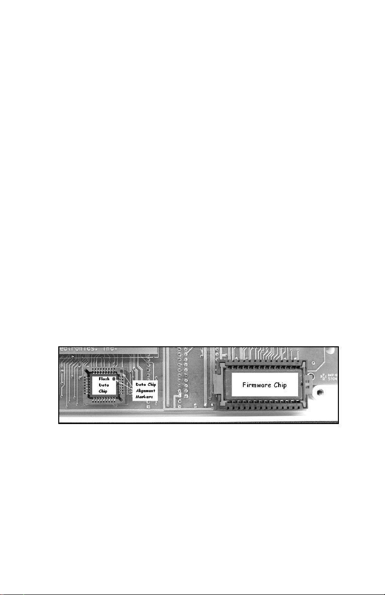
in the lower left corner (see Figure 9). To remove the
Data Chip, obtain a very small flat tip jewelers screw
driver. Insert the tip of the screw driver into one of the
two slotted corners of the socket and very gently pry
the corner of the Data Chip up a small amount.
Note: Do not try to pry the entire chip out at one time as this
may crack the socket.
Next, very gently pry the opposite slotted corner of the
Data Chip up. Repeat this process on both corners of
the Data Chip until it comes free from the socket.
Note: A chip extracting tool can also be made that is actually
easier to use than the screw driver. This can be accomplished by
straightening a small paper clip, giving one end a 1/16" “L” bend
and then bending a finger sized loop on the other end.
To use this tool, insert the “L” bend side of the tool into one of
the corner slots of the socket, allowing the bent portion to slip
underneath the bottom corner of the chip. Then gently pull the
tool (and corner of the chip) straight up out of the socket. Again,
this motion will probably have to be repeated on both sides to
extract the Data Chip.
Figure 9. Location of System Chips
To insert the Data Chip, orient the 45º flat corner of the
Data Chip with the 45º flat corner of the chip socket.
Firmly press the chip into the socket, ensuring that the
entire chip is inserted at the same depth all the way
around the socket.
INN-FORM XL BASIC 52
Page 62

CONNECTING THE PRINTER
Before you connect the printer, make sure that the
following is done on the printer and INN-FORM XL:
Set-up for All Printers:
Load the printer paper and set the top of page. Plug the
printer's AC power cord into a grounded outlet and
make sure that the printer is selected or on-line. Also,
perform any other necessary adjustments required by
the printer manufacturer (read the printer manual). To
make certain that the printer is operating properly, refer
to the printer manual for printer self test instructions.
Set-up if using a Serial Printer:
The pin configuration for the SERIAL RJ11 jack on
the back of the INN-FORM XL is as follows (See
Figure 10):
INN-FORM XL BASIC 53
Page 63
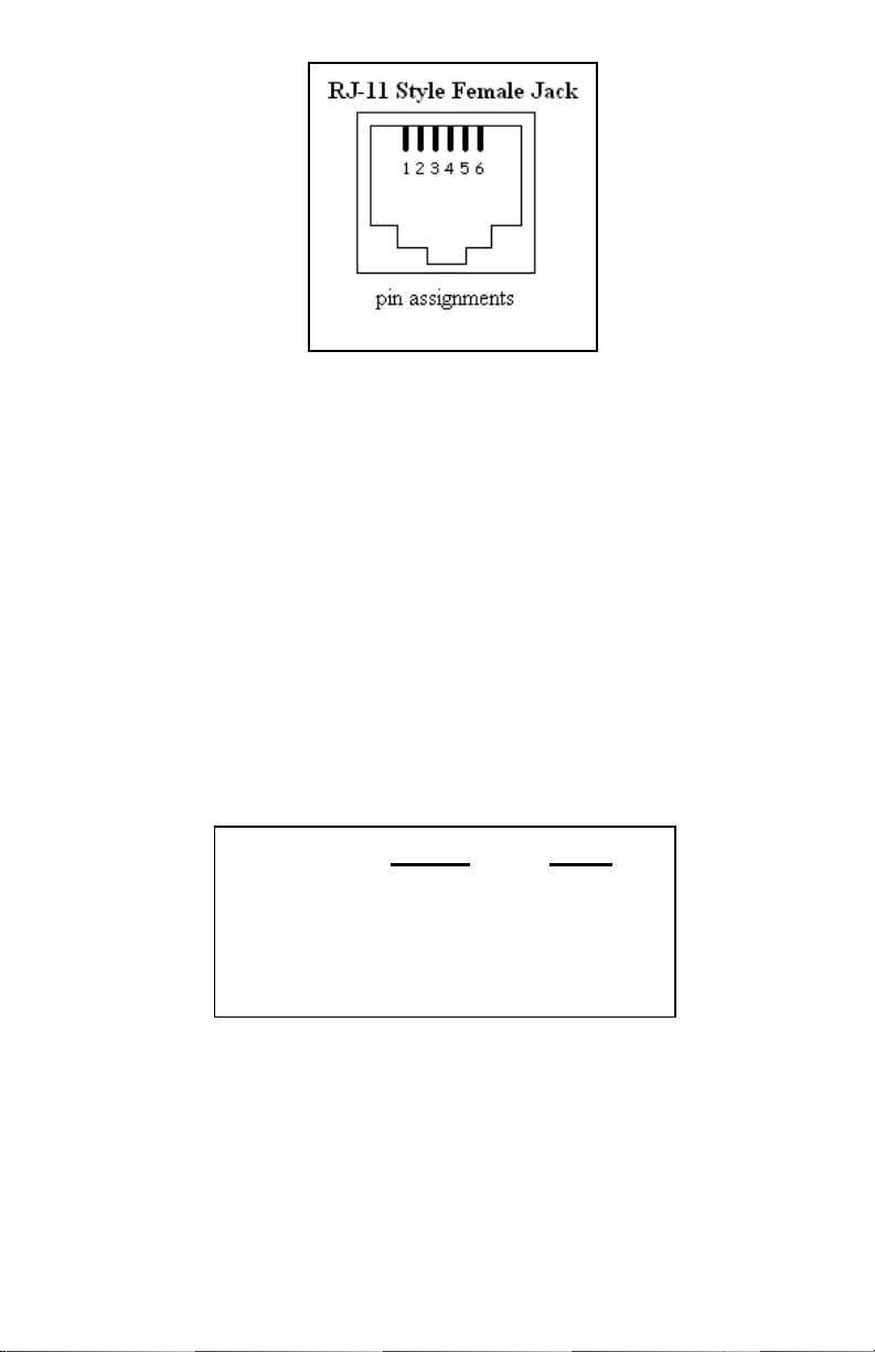
Figure 10. Serial Printer RJ11 Jack
• Pin 1-data terminal ready (DTR).
• Pins 3 & 4-signal ground. Connect signal ground to
either. Recommend: pin 3.
• Pin 5-Transmit data out to printer.
• Pin 6-Chassis ground.
NOTE: Pin 1 is a control line from the printer which, when high,
tells the system that it is ready to print. If it is missing or pulled to
0 volts, the INN-FORM XL will go into FIX PRINTER alarm.
When using the supplied RJ11-to-DB25M adapter, the
pin configuration on the adapter itself is as follows:
RJ11 DB25
CHASS GND 1 1
TX 2 3
GND 4 7
DTR 6 20
Figure 11. Pinout for Serial Printer
RJ11-to-DB25M Adapter
INN-FORM XL BASIC 54
Page 64
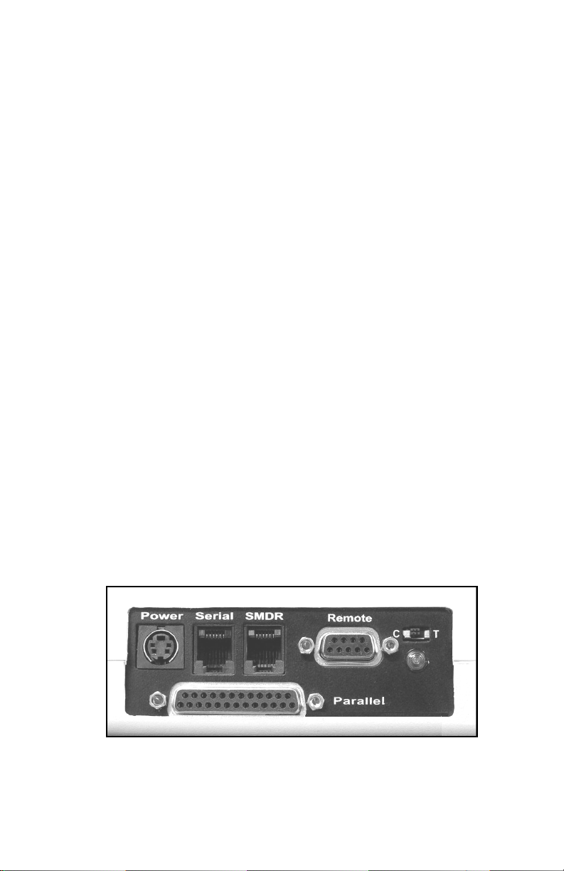
Steps for Serial Printer:
• Connect supplied RJ11-to-DB25 adapter cable to
the RJ11 jack on the back of the INN-FORM XL
labeled SERIAL (see Figure 12) and connect the
DB25 end of the adapter cable to the serial printer.
• Set Serial Printer settings to same baud rate as on
customer order form (follow the printer manual to
perform these steps).
• 7 or 8 data bits.
• 1 or 2 stop bits.
• Odd, Even or no parity.
• DTR on pin 20.
Note: If INN-FORM XL starts to alarm and displays "FIX
PRINTER" on start-up, when trying to use a serial printer, refer
to TROUBLESHOOTING portion of this manual.
Set-up if using a Parallel Printer:
• Connect a standard DB25-to-parallel printer cable
between the port labeled "PARALLEL" on the
INN-FORM XL (see Figure 12) and the printer
port.
Note: If INN-FORM XL starts to alarm and displays "FIX
PRINTER" on start-up when trying to use a parallel printer, refer
to TROUBLESHOOTING portion of this manual.
Figure 12. Back View of INN-FORM XL
INN-FORM XL BASIC 55
Page 65
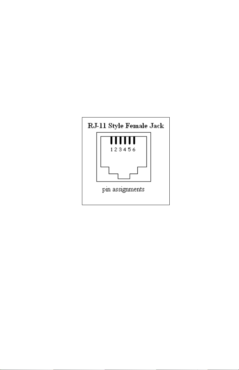
CONNECTING TO THE TELEPHONE SYSTEM
Before you actually connect the INN-FORM XL to the
telephone system, make certain that your telephone
system SMDR cable pinouts correspond to the INNFORM XL's SMDR connector. The female RJ11 style
modular jack, labeled SMDR is used for connection to
the SMDR output of the phone system. The pin
configuration on the SMDR port is as follows (see
Figure 13):
Figure 13. SMDR RJ-11 Jack
• Pins 2 & 5 are receive SMDR data. Only one
should be connected. Recommend: pin 2.
• Pin 3 & 4 are signal ground. Connect signal ground
to either. Recommend: pin 3.
• Pin 6 is +8V. Satisfies Data Terminal Ready
(DTR), if the phone system requires it.
You will notice there are no handshaking lines that
need to be connected to the INN-FORM XL. The
system is designed to receive data from the SMDR
device on a continuous basis, so handshaking is not
needed.
INN-FORM XL BASIC 56
Page 66

NOTE: It is very important that you understand the SMDR
equipment you are working on. The SMDR port on the phone
system must be configured to send data on a continuous basis (no
handshaking). It may be necessary to strap certain pins together
in order to satisfy handshaking requirements of the switch.
Now you can connect the telephone system to the INNFORM XL. Connect the SMDR cable from the
telephone system securely into the RJ11 style modular
jack in the back of the INN-FORM XL.
If the telephone system has an existing DB9 or DB25
connector, you will need a RJ11-to-DB9 or RJ11-toDB25 adapter. The pin configurations for either
adapter will be as follows:
RJ11 DB25 DB9
DTR 1 20 4
SMDR_IN 2 3 2
GND 4 7 5
SMDR_IN (recommended) 5 2 3
Figure 14. Pinout for SMDR RJ11-to-DB(25 or 9) Adapter
CONNECTING THE POWER
The INN-FORM XL needs a dedicated 120 volt AC
outlet. The outlet should have a standard socket with a
conduit ground. It is recommended that a separate 15
amp breaker and AC surge protection be used.
Once you're sure that you've provided the proper
environment, plug in the wall mount power supply.
Next, plug the DC power supply cable into the
POWER socket (see Figure 12).
INN-FORM XL BASIC 57
Page 67

The system will immediately transmit a Start-up or
Reset Report to the printer. The Start-up (or Reset)
Report includes the following information:
• Site Name, Area Code and Exchange.
• Serial number.
• Software version.
• System type and memory capacity
• Date, time, and day of week
• Mode setting.
• Current options.
If the Start-up Report prints, the unit is functioning
properly. If the Start-up Report does not print, make
sure that the printer/INN-FORM XL settings are
correct (including SMDR #18). Press the Reset
Button (located in the upper right corner of the unit;
the telephone with a dollar sign) and the Start-up
Report will appear. If not, repeat the steps in
Connecting the Printer. If troubles persist, refer to
the Troubleshooting section of the manual.
THE KEYPAD TEST
Press each key that is marked on the keypad and an
audible sound will be heard. This sound assures you
that each key is functioning. After testing each marked
key, press CANCEL several times to clear unwanted
commands. Call your dealer if unit doesn't pass this
test.
INN-FORM XL BASIC 58
Page 68

INITIALIZING THE SYSTEM
The initialization procedure will read factory loaded
specifications from the Data Chip. This process will
erase any on site programming and is necessary only
during the initial installation or if requested by
technical support.
>To initialize the system:
Step 1. Activate Management Access if necessary.
Step 2. Press PROGRAM.
Step 3. Enter 248.
Step 4. Press ENTER.
A reset message will show on the printer
along with the phrases:
8 0 0 0 21
DEFAULTS SET
2nd DEFAULTS SET
T
HE VALID CALL TEST
The Valid Call Test lets you know that the connection
between the INN-FORM XL and the telephone system
is good, that the phone system is transmitting call
records in a readable format and that the INN-FORM
XL is receiving, analyzing and storing these calls.
First, place the INN-FORM XL in mode 9 and run
Program 6. Press YES to the prompt, "PRINT 0 $?" in
order to print no cost calls. This will allow you to see
the data transmitted from the telephone system on the
printer and also see whether or not the INN-FORM XL
will accept that data format.
INN-FORM XL BASIC 59
Page 69

Now make three test calls. Make one local call, one
long distance call within your Area Code and one long
distance call outside of your Area Code. Make sure
that each test call lasts longer than the set grace period.
The first line of data on the printer should show the
SMDR as sent by the telephone system similar to the
following:
1234 00:01:45 00:00:00 9 2345533 T004
8/20 9:30AM Fri 101 UT (801)234-5533 2 $ 0.25 local call
EXAMPLE: Call Record Printed on Audit Trail (Mode 9).
The second line of data will be an Audit Trail in a TEL
electronics, inc. format to signify that the system
accepted the SMDR format.
If one of the following appear, refer to the
troubleshooting section:
• Checking fields bad
• Insufficient input
• Under grace period
CONNECTING THE REMOTE PORT
The Remote Port is used for external communication
between the INN-FORM XL and other RS-232
equipped systems. These types of systems include
Property Management Systems (PMS) as well as an
externally attached modem. To enable remote port
capability to DCE (Data Communication Equipment)
or DTE (Data Terminal Equipment), flip the switch on
the back of the system to the desired option "C" or "T"
INN-FORM XL BASIC 60
Page 70

respectively. (see Figure 12.) The green light located
under the switch will be lit when the port is configured
properly.
The remote port is configured as follows:
DCE (C) DTE (T )
Pin 3 Receive Pin 3 Transmit
Pin 2 Transmit Pin 2 Receive
Pin 5 Ground Pin 5 Ground
Pin4DTR Pin4DTR
Figure 15. INN-FORM XL DB9 Remote Port Pinout
To change the baud rate of the Remote Port see
instructions found in Program 26.
INN-FORM XL BASIC 61
Page 71

PROPERTY MANAGEMENT SYSTEMS (PMS)
This section describes the various Property
Management Systems (PMS) interface formats, and
how the INN-FORM XL implements each of these
standards. These three interface formats, include the
Holidex, Hobic, and Micros PMS standards.
Note: The following sections regarding PMS interfacing
do not apply to the INN-FORM XL with Reports version
because it has its own reporting capabilities and does not
use the Remote Port.
PMS-HX (HOLIDEX) INTERFACE
During normal use of the PMS interface the following
two conditions can exist:
CONDITION 1
The transmission is accepted and a one line Audit Trail
may be printed.
9/10 1:17AM Thu 211 NY 1(212)555-6789 28 $ 6.08 I
EXAMPLE: OneLineAuditTrail
Note: To omit the printing of the one line Audit Trail,
use Program 26 and respond with a "1" at the prompt,
"LINES/PAGE?"
The type of call is indicated by a single letter at the end
of the Audit Trail. A list of letters and their
corresponding type of call is shown below.
INN-FORM XL BASIC 62
Page 72

LETTER TYPE OF CALL
A...................................Local Calls
B...................................Local information
C...................................Information within the area code
D...................................Long distance call within the state
E...................................Call to a toll-free number (800)
F...................................Information out of the area code
G...................................Direct dialed international call
H...................................Operator assisted international call
I...................................Long distance out of the state
J...................................Operator assisted call
L...................................Call to balloting number (900)
M...................................Call within hotel (in-house)
N...................................Call to "nearby" local area, for measured service
O...................................Operator assisted long distance
P...................................WATS type call
Q...................................Special unique rate number (time numbers, etc.)
R...................................OCC type call
S...................................Incoming call
X...................................Unknown call
CONDITION 2
The transmission from the INN-FORM BASIC to a
Property Management System is not accepted. In that
event a 4 or 5 line Audit trail is printed so data is not
lost.
DATE TIME DAY EXTENSION MINUTES CHARGE
11/15 10:55AM Tue 210 19 9.20
TX 1(713)555-5614 out-of-state toll call
TEL electronics
EXAMPLE: Four line Audit Trail for HX
INN-FORM XL BASIC 63
Page 73

DATA FORMAT SPECIFICATION
This information will assist a technician in
understanding TEL's PMS-HX interface transmission
format and protocol. Each record sent from the call
accounting system conforms to the following format:
Field 1 2 3 4 5 6 7 8 9 10
001A TEL 05/12 621 19:19 0015 $006.51 212-555-4532 L
EXAMPLE: PMS-HX Interface Data Format
All fields are separated by one space except for fields
one and two, which are adjacent. For those fields
where leading zeros are not used, the data will be right
justified, occupying the right most position in the
number of bytes designated for that field.
INN-FORM XL BASIC 64
Page 74

Field 1
3bytes
F
IELD DESCRIPTIONS
Sequence number which increments
to 999 followed by 000. Every 24
hours it is cleared to 001
Field 2
1byte
Field 3
3bytes
Field 4
5bytes
Field 5
5bytes
Field 6
5bytes
Field 7
4bytes
Field 8
7bytes
Increments (A, B, ...) when Field 1
wraps around to 000. Every 24
hours it is cleared to A
Three character identifier which is
always "TEL."
Date of call. Leading zeros are sent
in both the month and day fields,
which are separated by a slash.
Room or extension which placed the
call. Leading zeros are not used
Time of call. Leading zeros are sent
in both the hour and minute fields,
which are separated by a colon
Call duration in minutes. Leading
zeros are sent.
Call cost in dollars and cents,
preceded by a dollar sign. Leading
zeros are sent in both the dollars and
cents fields, which are separated by
a decimal point.
Field 9
12 bytes
Field 10
1byte
Called number. This normally
consists of the area code, exchange
and the last four digits of the
number dialed, separated by dashes.
Local/Foreign indicator. L means
local, F means international, space
means anything else (typically long
distance).
INN-FORM XL BASIC 65
Page 75
Responses
1. Normal delivery of message to PMS.
TEL System External PMS
ENQ
ACK
STX (text) ETX BCC
ACK
2. Busy response by PMS
TEL System External PMS
ENQ
NAK (PMS
responds but
cannot ccept
data at this
time)
The TEL system will retransmit an ENQ after 5 seconds
until the PMS accepts the message, or until 4 NAK
responses are received.
3. No response from PMS.
TEL System External PMS
ENQ
(wait 5 seconds) (no response)
ENQ
(wait 5 seconds) (no response)
ENQ
(wait 5 seconds) (no response)
INN-FORM XL BASIC 66
Page 76
The INN-FORM XL BASIC HX will retransmit an
ENQ every five seconds until the PMS responds, or
until four unsuccessful ENQ responses have been sent.
4. Negative response to data transfer.
TEL System External PMS
ENQ
ACK
STX (text) ETX BCC
ENQ
(wait 3 seconds)
STX (text) ETX BCC (Max. of 3 tries)
NAK
ACK
If the message is still not successfully transmitted after
three tries, the TEL system will print the message on its
attached printer, and proceed to transmit the next
message.
5. No response to data transfer.
TEL System External PMS
ENQ
STX (text) EXT BCC
(wait 11 seconds) (no response)
ACK
ENQ
STX (text) ETX BCC (Max. of 3 tries)
INN-FORM XL BASIC 67
ACK
ACK
Page 77

In the event of no response to the data message, the
INN-FORM XL BASIC HX will reinitiate the ENQ
sequence.
If the message is still not successfully transmitted after
three tries, the INN-FORM XL BASIC HX will print
the message on its attached printer and proceed to
transmit the next message.
Specification Link Control Characters
ENQ -- A HEX 05 (ENQ) is used to request the status
of the PMS (ready/busy).
ACK - An ACK is used to represent a positive
acknowledgment by a Property Management System.
ACK will be sent to the TEL System in response to a
data transfer indicating successful reception of the data
by a Property Management System. ACK can be
defined by the property to be almost anything, although
a 06 (HEX 06) is recommended.
NAK - A NAK is used to represent a negative
acknowledgment by a Property Management System.
NAK will be sent to the TEL System in response to a
data transfer indicating unsuccessful reception of the
data by a Property Management System and requests
that the TEL System retransmit the data. NAK can be
defined by the property to be almost anything, although
a 21 (HEX 15) is recommended.
STX -- A HEX 02 (STX) -- This is the beginning frame
character during the transfer of data between the TEL
System and PMS. The STX also starts the accumulation
of the BCC.
INN-FORM XL BASIC 68
Page 78

ETX -- A HEX 03 (ETX) -- This is the last data
character and is followed immediately by the BCC.
BCC -- A HEX value representing the Block Check
Character used to verify the successful transfer of data
between systems. The BCC is calculated by processing
each character through an accumulator by an exclusiveor operation. The BCC process will start with the
character after the STX character, and includes and ends
with the ETX character. The BCC character will follow
the ETX character.
PMS-HB (HOBIC) INTERFACE
During normal use of the PMS interface the following
three conditions can exist:
CONDITION 1
The transmission is accepted and a one line Audit Trail
may be printed.
9/10 1:17AM Thu 211 NY 1(212)555-6789 28 $ 6.08 I
EXAMPLE: OneLineAuditTrail
Note: To omit the printing of the one line Audit Trail,
use Program 26 and respond with a "1" at the prompt,
"LINES/PAGE?"
The type of call is indicated by a single letter at the end
of the Audit Trail. A list of letters and their
corresponding type of call is shown below.
INN-FORM XL BASIC 69
Page 79

LETTER TYPE OF CALL
A...................................Local Calls
B...................................Local information
C...................................Information within the area code
D...................................Long distance call within the state
E...................................Call to a toll-free number (800)
F...................................Information out of the area code
G...................................Direct dialed international call
H...................................Operator assisted international call
I...................................Long distance out of the state
J...................................Operator assisted call
L...................................Call to balloting number (900)
M...................................Call within hotel (in-house)
N...................................Call to "nearby" local area, for measured service
O...................................Operator assisted long distance
P...................................WATS type call
Q...................................Special unique rate number (time numbers, etc.)
R...................................OCC type call
S...................................Incoming call
X...................................Unknown call
ONDITION 2
C
ACK and NAK are turned off in the INN-FORM XL
(see Program 33, SMDR #34 and #35), the
transmission is sent, and the INN-FORM XL prints a
one-line Audit Trail, regardless of whether the PMS
received, didn't receive, or acknowledged the call
record.
CONDITION 3
The transmission from the INN-FORM BASIC to a
Property Management System is not received or
accepted. In that event a 4 or 5 line Audit trail is
printed so data is not lost.
DATE TIME DAY EXTENSION MINUTES CHARGE
11/15 10:55AM Tue 210 19 9.20
TX 1(713)555-5614 out-of-state toll call
TEL electronics
EXAMPLE: Full Four-Line Audit Trail for HB
INN-FORM XL BASIC 70
Page 80

DATA FORMAT SPECIFICATION
This information will assist a technician in
understanding TEL's PMS-HB interface transmission
format and protocol. Each record sent from the call
accounting system conforms to the following format:
Field 1 2 3 4 5 6 7 8 9 10
001A TEL 05/12 621 19:19 0015 $006.51 212-555-4532 L
EXAMPLE: PMS-HB Interface Data Format
All fields are separated by one space except for fields
one and two, which are adjacent. (Field nine would
have four spaces if the phone number sent is lacking an
area code.) For those fields where leading zeros are not
used, the data will be right justified, occupying the right
most position in the number of bytes designated for that
field.
INN-FORM XL BASIC 71
Page 81

Field 1
3bytes
FIELD DESCRIPTIONS
Sequence number which increments
to 999 followed by 000. Every 6
hours it is cleared to 001
Field 2
1byte
Field 3
3bytes
Field 4
5bytes
Field 5
5bytes
Field 6
5bytes
Field 7
4bytes
Field 8
7bytes
Increments (A, B, ...) when Field 1
wraps around to 000. Every 6 hours it
is cleared to A
Three character identifier which is
always "TEL."
Date of call. Leading zeros are sent
in both the month and day fields,
which are separated by a slash.
Room or extension which placed the
call. Leading zeros are not used
Time of call. Leading zeros are sent
in both the hour and minute fields,
which are separated by a colon
Call duration in minutes. Leading
zeros are sent.
Call cost in dollars and cents,
preceded by a dollar sign. Leading
zeros are sent in both the dollars and
cents fields, which are separated by a
decimal point.
Field 9
12 bytes
Field 10
1byte
Called number. This normally
consists of the area code, exchange
and the last four digits of the number
dialed, separated by dashes. Where
appropriate, spaces are sent in place
of the area code and first dash
Local/Foreign indicator. L means
local, F means international, space
means anything else (typically long
distance).
INN-FORM XL BASIC 72
Page 82

RESPONSES WHEN NOT USING ACK/NAK
When software ACK and NAK are not used in INNFORM XL (SMDR#34 and #35 are both 0), the unit
will "blindly"send the call record to the PMS, and then
print the one-line audit trail.
TEL System External PMS
SOM (text) EOM
Response does not matter
A one-line audit trail is printed (if enabled).
RESPONSES WHILE USING ACK/NAK
A software handshaking protocol is expected to be used
only when ACK and NAK have been defined. When the
TEL system sends a message to the PMS the receiver of
the message can act in three ways. Positively
acknowledge, negatively acknowledge or not respond.
1. A positive response. The PMS acknowledges the
message.
TEL System External PMS
SOM (text) EOM
ACK
A one-line audit trail is printed (if enabled).
2. A negative response. The PMS returns a negative
acknowledgment. The TEL system waits three seconds
between retransmitting the second message and then if
necessary the third and final message. If an ACK is
received a one-line audit trail is printed. On the third NAK
or no response, a full four-line Audit Trail is printed.
INN-FORM XL BASIC 73
Page 83

TEL System External PMS
SOM (text) EOM
(wait 3 seconds)
NAK
SOM (text) EOM
(wait 3 seconds)
SOM (text) EOM
NAK
3. No response. If the PMS does not respond to the TEL
message the TEL system will print a full four-line Audit
Trail.
TEL System External PMS
SOM (text) EOM
(wait 5 seconds) (no response)
The TEL system prints a full four-line Audit trail.
Specification Link Control Characters
ACK - An ACK is used to represent a positive
acknowledgment by a Property Management System. ACK
will be sent to the TEL System in response to a data
transfer indicating successful reception of the data by a
Property Management System. ACK can be defined by the
property to be almost anything, although a 06 (HEX 06) is
most commonly used.
NAK - A NAK is used to represent a negative
acknowledgment by a Property Management System. NAK
will be sent to the TEL System in response to a data
transfer indicating unsuccessful reception of the data by a
Property Management System and requests that the TEL
System retransmit the data. NAK can be defined by the
property to be almost anything, although a 21 (HEX 15) is
most commonly used.
INN-FORM XL BASIC 74
Page 84
SOM, EOM -- A Start-of-Message (SOM) sequence is used
to precede the text, and an End-of-Message (EOM)
sequence ends the text. The defaults are set to LF for SOM
(HEX0A),andCR,LF,FFforEOM(HEX0D0A0C).
PMS-MR (M
ICROS) INTERFACE
During normal use of the PMS interface the following
two conditions can exist:
CONDITION 1
The transmission is accepted and a one line Audit Trail
may be printed.
9/10 1:17AM Thu 211 NY 1(212)555-6789 28 $ 6.08 I
EXAMPLE: One Line Audit Trail
Note: To omit the printing of the one line Audit Trail,
use Program 26 and respond with a "1" at the prompt,
"LINES/PAGE?"
The type of call is indicated by a single letter at the end
of the Audit Trail. A list of letters and their
corresponding type of call is shown below.
INN-FORM XL BASIC 75
Page 85

LETTER TYPE OF CALL
A...................................Local Calls
B...................................Local information
C...................................Information within the area code
D...................................Long distance call within the state
E...................................Call to a toll-free number (800)
F...................................Information out of the area code
G...................................Direct dialed international call
H...................................Operator assisted international call
I...................................Long distance out of the state
J...................................Operator assisted call
L...................................Call to balloting number (900)
M...................................Call within hotel (in-house)
N...................................Call to "nearby" local area, for measured service
O...................................Operator assisted long distance
P...................................WATS type call
Q...................................Special unique rate number (time numbers, etc.)
R...................................OCC type call
S...................................Incoming call
X...................................Unknown call
ONDITION 2
C
The transmission from the INN-FORM BASIC to a
Property Management System is not accepted. In that
event a 4 or 5 line Audit trail is printed so data is not
lost, as shown below.
DATE TIME DAY EXTENSION MINUTES CHARGE
11/15 10:55AM Tue 210 19 9.20
TX 1(713)555-5614 out-of-state toll call
TEL electronics
EXAMPLE: Four line Audit Trail for MR
INN-FORM XL BASIC 76
Page 86

DATA FORMAT SPECIFICATION
This information will assist a technician in
understanding TEL's PMS-MR interface transmission
format and protocol.
Each record sent from the call accounting system
conforms to the following format:
Field 1 2 3 4
ac0103100006563125341234
EXAMPLE: PMS-MR Interface Data Format
All fields are adjacent (no spaces). The message is
always followed by a carriage return (HEX 0D) with
no line feed.
Field Descriptions
Field 1
4bytes
Start of Message. A four character identifier
which is always “ac01.”
Field 2
4byte
Field 3
6bytes
Field 4
10 bytes
Room or extension which placed the call.
Call Charge. The amount is represented in
pennies (i.e. no decimal point).
Telephone number. The telephone number
field always contains 10 digits.
INN-FORM XL BASIC 77
Page 87

Responses
When the TEL System sends a message to a Property
Management System the receiver of the message can
acknowledge or not respond.
1. A positive response. A Property Management System
acknowledges the message.
TEL System External PMS
text plus carriage return
ACK
A one line audit trail record is printed.
2. A negative response. A Property Management System
returns a negative acknowledgment. The TEL system waits
3 seconds before retransmitting the final message. If an
ACK is received the system proceeds normally. On a
NAK or no response the TEL system will print a full fourline Audit trail.
TEL System External PMS
text plus carriage return
(wait 3 seconds) NAK
text plus carriage return
INN-FORM XL BASIC 78
Page 88

3. No response. If a Property Management System does
not respond to the message, the TEL system will print a full
Audit trail.
TEL System External PMS
text plus carriage return
(wait 5 seconds) (no response)
The TEL system prints a full four-line Audit trail.
Specification Link Control Characters
ACK - An ACK is used to represent a positive
acknowledgment by a Property Management System.
ACK will be sent to the TEL System in response to a
data transfer indicating successful reception of the data
by a Property Management System. ACK can be
defined by the property to be almost anything, although
an ASCII "y" 121 (HEX 79) is recommended.
NAK - A NAK is used to represent a negative
acknowledgment by a Property Management System.
NAK will be sent to the TEL System in response to a
data transfer indicating unsuccessful reception of the
data by a Property Management System and requests
that the TEL System retransmit the data. NAK can be
defined by the property to be almost anything, although
an ASCII "n" 110 (HEX 6E) is recommended.
INN-FORM XL BASIC 79
Page 89

TROUBLESHOOTING
TROUBLESHOOTING
Troubleshooting can often be handled on site by
operating personnel without incurring extra expense or
waiting for an outside service technician. During
normal operation, a number of things can happen
which appear to be serious, but which are simply
system responses to unusual activities (power
fluctuations, extreme static electricity, accidental
unplugging of the system, etc.).
SYMPTOM:
INN-FORM XL display remains blank or shows
faint gray or black boxes.
POSSIBLE CAUSES:
INN-FORM XL power cord not plugged in.
Static electricity has temporarily erased the display.
Data or Firmware chip inserted incorrectly on chip
change.
SUGGESTED ACTION:
Make sure INN-FORM XL power cord is plugged
into a working properly grounded 110 - 120 volt
A.C. outlet.
If firmware and/or datachip was just changed, verify
that chips are inserted correctly.
Wait for one minute and the system will reset the
display as it updates its configuration.
INN-FORM XL BASIC 80
Page 90

SYMPTOM:
Unit powers up, but continually resets itself, never
displays anything and beeps.
POSSIBLE CAUSES:
A.C. voltage is not 110-120VAC.
SUGGESTED ACTION:
Use a Uninterruptible Power Supply (UPS) to
ensure that A.C. voltage going to INN-FORM XL
wall transformer is clean 110-120VAC.
Try plugging the unit into a wall outlet on another
side of the building to test a different AC line.
SYMPTOM:
INN-FORM XL is not printing to the Serial Printer.
POSSIBLE CAUSES:
INN-FORM XL attempting to print through the
Parallel Printer Port instead.
Serial communications configuration between INNFORM XL and printer do not match.
Cable not attached or cable pinout not correct.
SUGGESTED ACTION:
Ensure that SMDR #18 is set to 1 (see Program 33).
Ensure the printer is properly set-up: power, on-line,
printer selected, self test, paper, etc.
Ensure that printer's serial communication
configurations match that of the INN-FORM XL:
baud rate, data bits (7 or 8), stop bits (1 or 2), parity
INN-FORM XL BASIC 81
Page 91

(even, odd, or none), DTR on pin 20. see Programs
26 and Program 33 (SMDR #47). See printer
manual to find these values as well.
Check to see if the male DB25 adapter from INNFORM XL Serial Printer Port is securely fastened.
Perform a Program 88 Loop Test (see Program 88
below), to confirm that INN-FORM XL Serial Port
is functioning correctly.
SYMPTOM:
INN-FORM XL is not printing to the Parallel Port:
POSSIBLE CAUSES:
INN-FORM XL is attempting to print through the
Serial Printer Port instead.
Parallel Printer cable not connected.
SUGGESTED ACTION:
Ensure that SDMR #18 is set to 0 (see Program 33).
Ensure that printer is properly set-up: power, online, printer selected, self test, paper, etc.
Verify that the parallel printer is connected to the
Parallel Printer Port on the INN-FORM XL.
SYMPTOM:
The INN-FORM XL is not printing or posting call
records from the telephone system. This symptom
assumes that the printer is at least able to print the
reset message or reports.
INN-FORM XL BASIC 82
Page 92

POSSIBLE CAUSES:
Audit Trail not turned on.
Serial communication configurations of INNFORM XL and phone system do not match.
INN-FORM XL sees SMDR data but is not
configured to interpret it correctly.
Telephone system not sending out SMDR data for
some reason.
SMDR cabling from phone system either not
connected to INN-FORM XL or not wired correctly.
SUGGESTED ACTION:
Place the INN-FORM XL in mode 9 (see Setting the
Mode). This diagnostic mode will echo any data
that is sent from the telephone system to the INNFORM XL directly to the printer.
When performing test calls, the green SMDR
DATA light should flicker when a call is finished.
This LED indicates the unit is receiving data from
the telephone system. If it does not flicker when a
call is finished it is an indication that the INNFORM XL is not receiving any data from the
telephone system, or there is something wrong with
the INN-FORM XL. Run Program 88 to verify if
SMDR Port is functioning at this point.
If the SMDR DATA light DOES flicker after a test
call is completed and intelligent information is still
not printed in Mode 9, it is probably an indication
that the serial communication configurations
between the INN-FORM XL and the phone system
do not match. Check the baud rates in Program 26,
INN-FORM XL BASIC 83
Page 93

and also the protocol values in Program 33 (SMDR
#47) if this happens. Be sure the pinouts for the
cabling are correct and that the telephone system is
able to send data on a continuous basis
(handshaking is not required).
See Programs 32 and 33 if some adjustments to the
SMDR programming are necessary.
Run Program 88 (see below) to ensure INN-FORM
XL SMDR and Serial Ports are functioning
properly.
SYMPTOM:
INN-FORM XL receives calls, and is able to print a
call record to the printer, but is not able to post the
call record to the PMS.
POSSIBLE CAUSES:
Cable to PMS not connected or incorrect.
Serial Communication configurations between PMS
and INN-FORM XL do not match.
Remote Port C/T Switch in incorrect position.
PMS is not accepting serial communications from
the INN-FORM XL.
RS-232 circuitry in PMS faulty.
Incorrect PMS format being used.
SUGGESTED ACTION:
Make sure cable is attached from INN-FORM XL
Remote Port to the PMS.
INN-FORM XL BASIC 84
Page 94

Ensure that Program 26 Baud Factor value is correct
to enable INN-FORM XL Remote Port baud rate to
match that of the PMS.
Ensure that the serial communications protocols for
the INN-FORM XL Remote Port match that of the
PMS (see Program 33 SMDR #47).
Position the Remote Port C/T Switch in back of
INN-FORM XL so that green C/T light is lit. If
light is not lit in either position, then there is a
cabling issue from the PMS (voltage to this light is
supplied by the PMS).
Ensure that the INN-FORM XL PMS format is
correct. The PMS format can be verified by
inspecting the INN-FORM XL reset start-up
message.
Verify if the PMS format requires ACK/NAK
handshaking, and that these are set correctly (see
Program 33, SMDR #34 and #35).
Contact PMS vendor and have them re-boot the
PMS.
Possibly have vendor replace PMS serial card.
Perform a Program 89 on the unit to verify
INN-FORM XL Remote Port is functioning
properly.
SYMPTOM:
INN-FORM XL sounds alarm.
INN-FORM XL BASIC 85
Page 95

POSSIBLE CAUSES:
Printer 110 - 120 volt A.C. cord is not plugged in.
Printer is not selected or on-line.
Printer is out of paper or ribbon.
Printer cable is not properly connected.
Memory is low.
System is waiting for a response to a prompt
"ANOTHER?"
A 911 or 311 call has been placed.
An extension has exceeded its’ programmed credit
limit.
A device connected to the Remote Port is no longer
enabled and ready to communicate with the XL.
INN-FORM XL is trying to send data to printer, and
SMDR #18 is set to incorrect printer type.
SUGGESTED ACTION:
Make sure printer power cord is plugged into 110 120 volt A.C. grounded outlet
Place printer in SELECTED or ON-LINE mode.
See printer manual.
Load paper or ribbon according to instructions in
printer user manual.
Make sure that the cable between INN-FORM XL
and the printer is plugged in properly.
INN-FORM XL BASIC 86
Page 96

Unplug the PMS cable at the INN-FORM XL
Remote Port. If alarm goes out then there is a
problem with the PMS.
Run an Audit Report.
Plug system into a more reliable power source or
UPS.
Answer the prompt.
Press the “C” key to silence and clear a 911 / 311 or
Credit Limit Alarm.
SYMPTOM:
INN-FORM XL does not price certain short
duration calls.
POSSIBLE CAUSE:
Grace Period is set too long
SUGGESTED ACTION:
See Program 2
SYMPTOM:
INN-FORM XL prices some calls incorrectly
POSSIBLE CAUSE:
Phone tariffs have changed.
SUGGESTED ACTION:
Make adjustments in Program 3, Cost Adjustments,
or contact your dealer for tariff updates.
INN-FORM XL BASIC 87
Page 97

PROGRAM 0 (SIMULATE TEST CALL)
This program simulates SMDR for the INN-FORM XL
to process. It is useful for testing pricing, printing,
storing, and PMS posting of call records.
> To run Program 0:
Step 1. After you've entered your management
access code: Press PROGRAM.The
system will display, "PROGRAM".
Step 2. Enter 0. The display will show:
CALL?
Step 3. Enter 9, followed by the phone number.
The last four digits of the phone number
entered will be used as the extension for the
call record.
EXAMPLE: Simulated test phone number.
918017560123
This number sequence would simulate a random
duration phone call to (801)756-0123 originating
from extension #123.
EXAMPLE: Simulated test phone number.
97561103
This number sequence would simulate a random
duration phone call to 756-1103, with the home
area code, originating from extension #1103.
Step 4. Press ENTER.
The INN-FORM XL will generate a simulated
INN-FORM XL BASIC 88
Page 98

call record of random call duration. The simulated call
record will process exactly as if it had been received
from the phone system. This includes: pricing the call
record, printing the Audit Trail (if it is enabled),
storing the priced call (if this is a Reports version),
adding it to the Activity and Trunk Reports, and
posting it to a PMS (if attached).
Note: Because the call accounting system will treat this
simulated call exactly as if it were a real call, caution
should be used on which extension is used. The charged
callwillbepostedtothePMSorstoredincallrecord
memory using this extension.
Note: The beginning 9 has to be included for this test.
PROGRAM 88 (SERIAL LOOP TEST)
This test is used to test the functionality of the Serial
Port and the SMDR Port of the INN-FORM XL.
> To run Program 0:
Step 1. On the INN-FORM XL, disconnect both the
SMDR and serial printer cables from the
SMDR and Serial Ports.
Step 2. Connect one end of a 6 conductor telephone
line cord to the SMDR port of the INNFORM XL. Connect the other end of this
cord to the Serial Port of the INN-FORM XL.
Note: If you are using the telephone line cord and adapter
supplied by TEL electronics to attach the INN-FORM XL to a
serial printer, you can use that telephone line cord for this test.
Step 3. While in Management Access, set the
operation mode to 0 (see Setting the Mode).
INN-FORM XL BASIC 89
Page 99

Step 4. In management access, press PROGRAM.
Step 5. Enter 88 and press ENTER.
The system will send data from the SERIAL port to
the SMDR port. The green SMDR DATA light
should flicker momentarily and the display should
read, "PORTS OK". This verifies that the SMDR
and Serial ports are functioning. If these events do
not occur the unit requires repair.
PROGRAM 89 (REMOTE PORT LOOP TEST)
This program is used to ensure that the Remote Port on
the INN-FORM XL is functioning correctly.
> To run Program 0:
Step 1. Disconnect any cable that might be plugged
into the REMOTE port.
Step 2. Find a small piece of wire (i.e. small paper
clip).
Step 3. Insert one end of the wire into pin 2 of the
remote port and the other end into pin 3 (Pin
numbers are on the connector).
Step 4. At this point the green light on the back of
the IFXL should light up, regardless of the
position of the C/T switch. If it doesn’t light
up then one of the following is happening:
• The wire is not inserted into the correct
pins of the remote port.
INN-FORM XL BASIC 90
Page 100

• The remote port light is not working
correctly.
• The remote port is bad, and the unit will
have to be repaired.
Step 5. After entering the management access code:
Press PROGRAM. The system will display
“PROGRAM”.
Step 6. Enter 89.
Step 7. Press ENTER.
At this point the system will display
“RMT PORT GOOD”. This indicates that
the remote port is working correctly. This is
true regardless of the position of the C/T
switch. If this does not happen then most
likely the remote port of the IFXL is bad and
the unit will need to be repaired or replaced.
Step 8. Repeat this test with the C/T Switch in the
opposite position as well, to ensure switch is
working as well.
If the results above are not observed then the
INN-FORM XL requires repair.
INN-FORM XL BASIC 91
 Loading...