

Telehook TH-3070-UFL Installation Instructions Manual
TH-3070-UFL
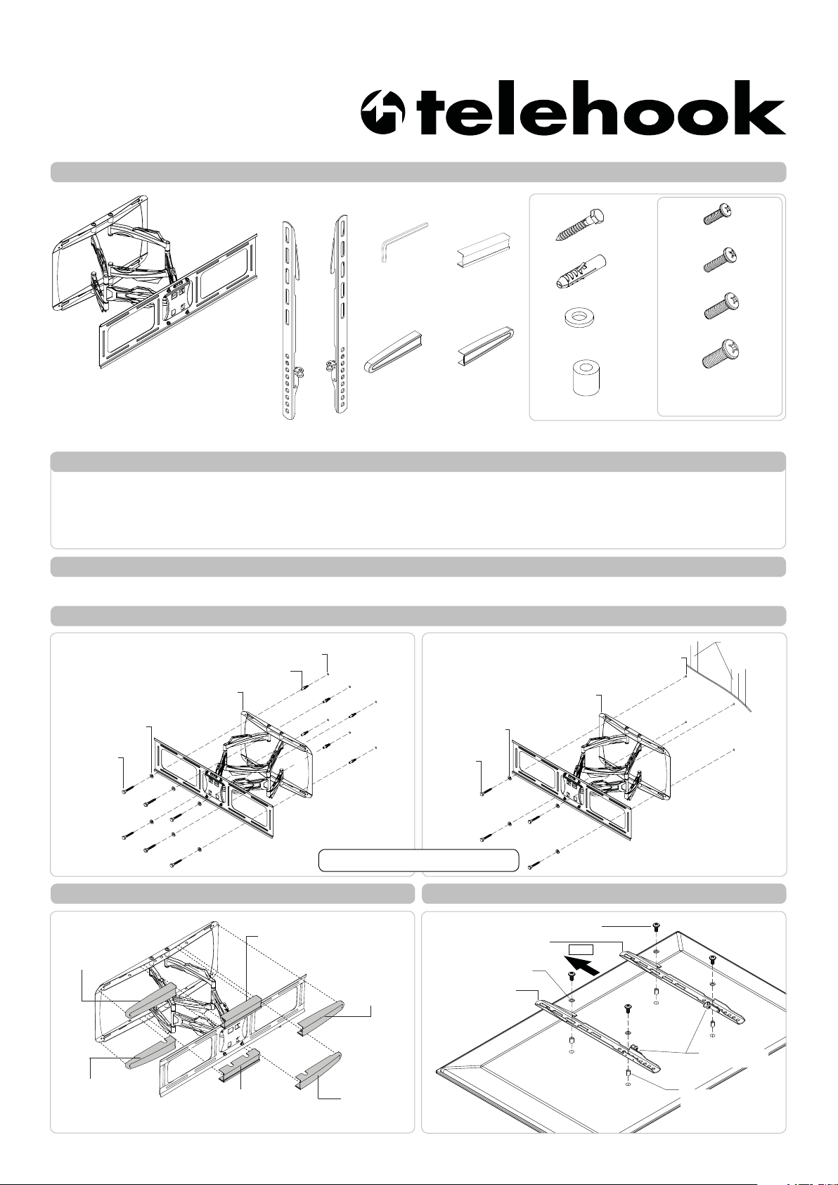
Component Checklist
Installation Instructions
Large-Medium TV l Articulated Arm
Arm/Wall Mount
Tools Required:
• Power Drill
• 3mm(0.12”) Drill Bit
• 10mm(0.39”) Masonry Drill Bit
• Phillips head screw driver
• 13mm(0.5”) Socket Wrench or Shifter
Right Mounting
Bracket
Left Mounting
Bracket
Allen Key
Wall Mount
Cover Left (x2)
Wall Mount Cover
Centre (x2)
Wall Mount
Cover Right (x2)
Hardware
Coach Screw (x6)
Nylon Anchor (x6)
M8 Washer (x6)
M6.5 Washer (x4)
M8 Spacer (x4)
M6x12 (x4 each)
M6x30mm (x4 each)
M8x16mm (x4 each)
M8x30mm (x4 each)
Display Mounting
Screws
IMPORTANT INFORMATION:
! IMPORTANT - Install Telehook 3070 Large-Medium TV Articulated Arm Mount as per installation instruction.
! This product supports a maximum load of 60kg (132lbs.).
! This product has a universal mounting hole pattern that suits a broad range of TV’s:
From 200-800mm in width and 200-400mm in height.
! The manufacturer accepts no responsibility for incorrect installation.
Step 1. Check Components
Check you have received against the component checklist and hardware above.
Step 2. Install Arm/Wall Mount to the Wall
Masonry Wall Timber Stud Wall
Nylon Anchor (x6)
Arm/Wall Mount
M8 Washer (x6)
Coach
Screw (x6)
Ø10mm(0.4”)
Drilled Hole
Arm/Wall Mount
M8 Washer (x4)
Coach
Screw (x4)
Tip: Use a spirit level to ensure
wall plate is horizontal.
Ø5mm(0.2”)
Drilled Hole
Note: Use a stud finder to
accurately locate the center of
the stud. Ensure that all screws
fix securely into the stud.
Timber Studs
Step 3. Attach Wall Mount Covers Step 4. Attach Mounting Brackets to Display
Mounting Screw
Bracket
Washer
TOP
Wall Mount
Cover Left
Wall Mount
Cover Centre
Wall Mount
Cover Right
Right Mounting
Left Mounting
Bracket
Wall Mount
Cover Right
Wall Mount
Cover Centre
Wall Mount
Cover Left
Ensure locking
screw is in inside.
Spacer
(optional, use only
for recess mounting
holes)
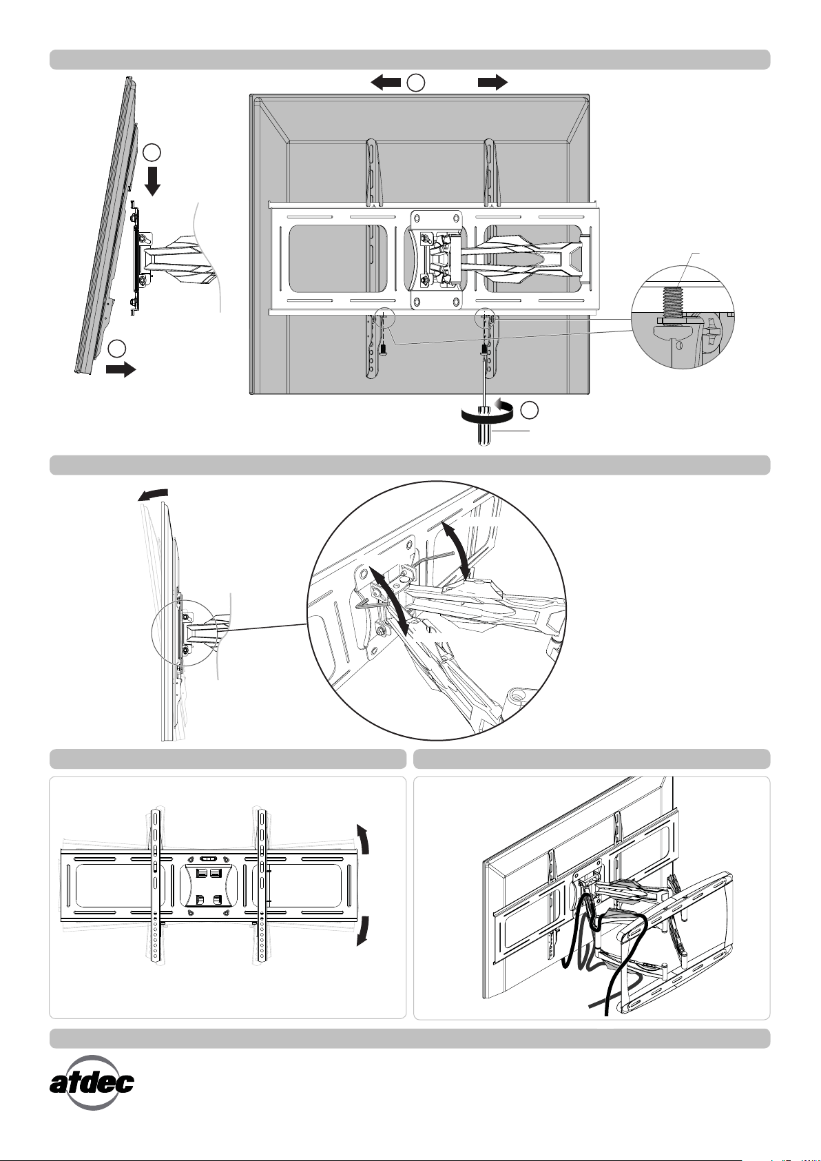
Step 5. Attach Display to the Arm/Wall Mount
3 CENTER
1 HOOK
2 PUSH
1. Hook the display to the mounting
plate.
2. Push the bottom of the display.
3. Ensure display is positioned in the
center of the mounting plate.
4. Tighten the locking screws using a
phillips head screw driver.
Locking Screw
4 TIGHTEN
Phillips Head Screw Driver
Step 6. Tilt Adjustment
10°
TIGHTEN
LOOSEN
TIGHTEN
LOOSEN
Depending on the weight of your display,
you may need to use the supplied allen
key to tighten and loosen the screws for tilt
tension adjustment.
Step 7. Horizontal Adjustment Step 8. Cable Management
Insert cables into the four clips
provided.
+2°
Installation Complete
No portion of this document or any artwork contained herein should be reproduced in any way without the express written consent of Atdec Pty Ltd.
Due to continuing product development, the manufacturer reserves the right to alter specifications without notice. Published 02.11.12 ©
-2°
 Loading...