

Telehook TH-3070-CTL, TH-3070-CTLW, TH-3070-CTSW, TH-3070-CTS Installation Instructions Manual
Installation Instructions
TH-3070-CTL
TH-3070-CTS
TH-3070-CTLW
TH-3070-CTSW
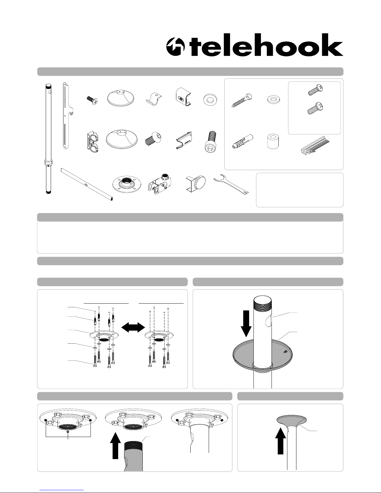
Component Checklist
Ceiling Tilt Short Mount / Ceiling Tilt Long Mount
Mounting
Cover
Horizontal Rail
M6/M8
Spacer (x4 each)
2mm/2.5mm/3mm
5mm/8mm Allen Key
M10 Coach
Bolt (x4)
Nylon
Anchor (x4)
HARDWARE
Display Mounting
Screws (x4 each)
M6x16mm/30mm/45mm
M8x16mm/30mm/50mm
Tools Required:
• Power Drill
• 7mm(0.25”) Drill Bit
• 12mm(0.5”) Masonry Drill Bit
• Phillips head screw driver
• 17mm(0.7”) Socket Wrench or Shifter
Mounting
Bracket (x2)
Pole
Assembly
Ceiling Cover
! IMPORTANT - Install Telehook Ceiling Mount as per installation instruction.
! This product supports a maximum load of 65kg (143lbs.).
! This product has a universal mounting hole pattern that suits a broad range of TV’s:
From 200-800mm in width and 200-500mm in height.
! The manufacturer accepts no responsibility for incorrect installation.
IMPORTANT INFORMATION:
Step 1. Check Components
Check you have received against the component checklist and hardware above.
Step 2. Install Mounting Plate to the ceiling
Using the Mounting Plate as a template, mark and drill 4 holes.
NOTE: Drilled hole sizes,
For Masonry Ceiling, Ø12mm (0.5”) and 70mm (2.75”) deep.
For Timber Ceiling, Ø7mm (0.75”).
Masonry Ceiling
Timber Ceiling
Drilled Holes
Nylon Anchor
Mounting Plate
M10 Washer
Coach Screw
Step 3. Install Mounting Cover
PUSH
Pole Assembly
Mounting Cover
Step 4. Attach Pole Assembly to Base Plate
Remove the three set
screws using the supplied
3mm Allen Key.
Set Screws
INSERT
Insert the three set screws
using the supplied 3mm
Allen Key to secure.
4A 4B 4C
Pole Assembly
Step 5. Position Mounting Cover
PUSH
Mounting
Cover
Mounting
Plate
Bracket Locking
Plate (x2)
M8x15mm
Screw (x2)
Cable
Clip (x2)
M4x12mm
Screw (x2)
Clamp Cover
Bottom
Clamp Cover
Middle
Clamp Cover
Side (x2)
Head Clamp
Assembly
Tightening Tool
M6/M8/M10
Washer (x4 each)
OR
M10x30
Screw
M10
Washer
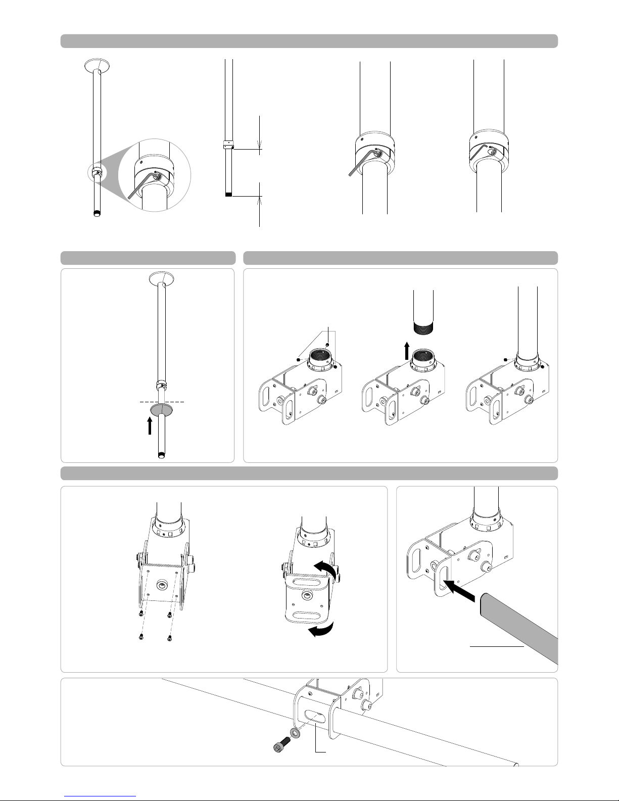
Step 7. Install the Ceiling Cover
Step 9. Install the Horizontal Rail
Step 6. Set the Height of the Pole
Whilst supporting the lower half of Pole
Assembly loosen the Socket Cap Screws
(x2) using the supplied 5mm Allen Key.
Slide Pole Assembly to the
desired height.
Height Adjustment
CTL: 1050-1900mm
CTS: 550-900mm
Tighten the Socket Cap Screws
(x2) to set the height using the
supplied 5mm Allen Key.
If necessary, centralise the Pole Joint
by tightening the Set Screws (x2) to suit
using the 2.5mm Allen Key.
6A
6B 6C 6D
Push up to the ceiling
Step 8. Install the Clamp Head
Loosen the three set screws
using the supplied 3mm Allen
Key.
Set Screws
ATTACH
Secure the collar with the
three set screws using the
supplied 3mm Allen Key.
8A 8B 8C
1. Loosen the 4 screws using the supplied
2.5mm Allen Key.
2. Rotate the head clamp 90° and insert
the 4 screws again using the supplied
2.5mm Allen Key.
9A. To Set Orientation
NOTE: The rail mount is factory set in
the horizontal axis.
INSERT
Horizontal Rail
9B. Insert
Horizontal
Rail
9C. Secure Horizontal Rail
1. Make sure the large slot of Horizontal Rail is facing front.
2. Align the holes of the Horizontal Rail and Head Clamp.
3. Lock in place with M10 Screw and Washer using the
supplied M8 Allen Key.
If the lower pole hangs
below a suspended
ceiling, push the ceiling
cover up to the ceiling.
Large Slot
 Loading...