

Page 1
Commissioning and Functional Description
Wiring Test
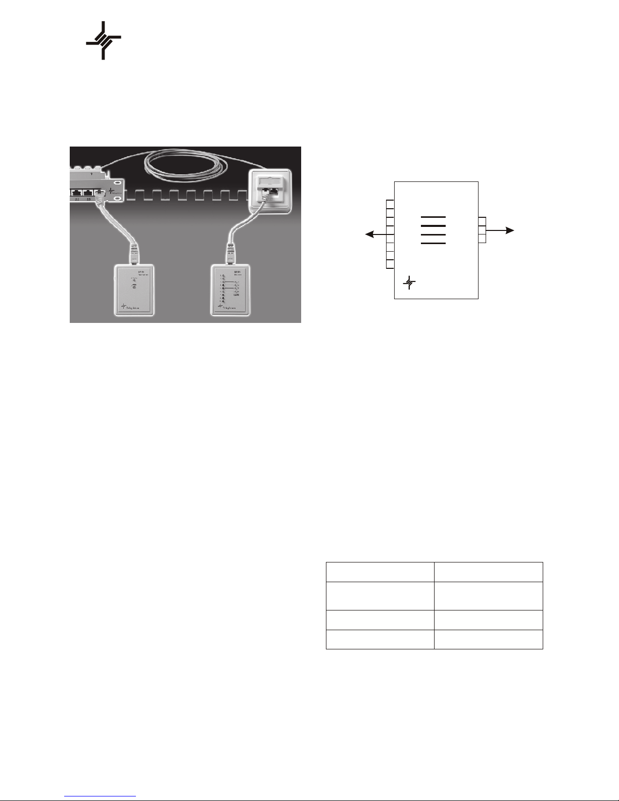
Contact the transmitter to one end of the
cable.
Using a screwdriver, adjust the ash frequency
at the transmitter's potentiometer.
Contact the receiver against the opposite end
of the cable.
Display Evaluation at the Receiver
All LEDs go on in
sequence.
One or more LEDs fail
to go on.
Connection OK
The lead for which the
associated LED fails to go
on is interrupted.
Several LEDs fail to
go on in sequence.
The lead sequence
is incorrect.
Two or more LEDs
are on simultaneously.
Short circuit between
the indicated leads.
4-wire cable check
LEDs 1 - 4 go on sequentially.
4-wire shielded cable check
LEDs 1 - 4 + S go on sequentially
8-wire cable check
LEDs 1 - 8 go on sequentially.
8-wire shielded cable check
LEDs 1 - 8 + S go on sequentially.
The UCT9 LAN wiring tester is a device
which allows single-person testing of
multiple lead cable and line systems.
In addition, it is equipped with an integrated
ISDN interface for simplied fault
recognition of the most wiring faults.
LEDs on the UTC9 receiver indicate the
occupancy of the connecting wires.
Terminal
designation
Lead
designation
IS DN
1
2
3
4
5
6
7
8
S
2a
1a
1b
2b
R ece ive r
UC T 9
Te leg är tne r
Performance features
Recognition and indication of the most
common installation faults: short circuit,
lead reversal, lead interruption;
LEDs provide fault indication for each
individual lead.
Automatic test procedure.
Easy to use and easy interpretation of the
results.
Adjustable test speed.
9-pin connecting line to allow testing of up
to 8-lead lines, with shielding.
Battery connection reversal protection.
Resistant to external voltage up to 60V.
MS Windows -based evaluation
software.
�
UCT9
Telegär tn er
Operating Instructions
Page 2
2.
2.1
2.2
Installation Tests
During testing, the NTBA must be in the
normal mode and the terminal resistors
must not be installed.
Testing the Connection Sockets
A patch cable is used to sequentially check each
connection socket
(See below for the evaluation of the displayed
results.)
ISDN Terminal Device Connecting Cord
Connect the cord to the UTC9 .
(See below for the evaluation of the displayed
results.)
Expanded Test for SO Bus Installation
Where an ISDN installation contains more than
one ISDN terminal device, leads 2a and 2b must
not be reversed.
To eliminate the possibility that these two leads
are reversed, lead 2a is interrupted at the rst
opportune location in the ISDN installation. This
interruption of lead 2a must then be indicated on
the UTC9 at the connection socket. If the UTC9
indicates that lead 2b is interrupted, the leads
have been reversed.
Once all reversals have been corrected, the
interruption to lead 2a can be removed.
3.
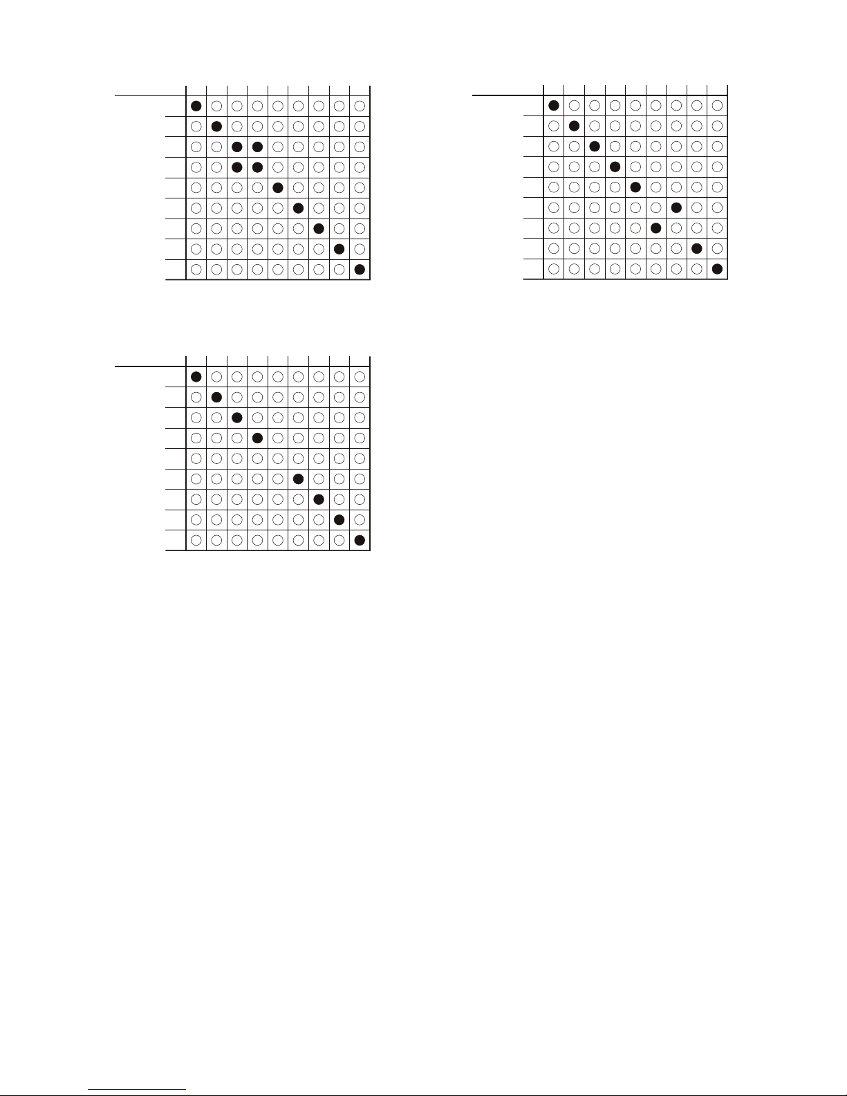
Example: 6 + 7 reversed
In the case of crossed wires, the correct
wiring can only be ensured if the shield is
also connected. Otherwise, interrupt any
lead at the transmitter and check that the
associated indicator on the receiver fails to
go on.
Frequency/step 1 2 3 4 5 6 7 8 9
1
2
3
4
5
6
7
8
S
LE D
ISDN Test (ISDN LED)
Only the receiver is required to test
ISDN- S0 connections.
NTBA Connection Test
Test the ISDN connection at the NTBA in both
the normal and emergency modes.
Normal mode: NTBA is connected to the 230V
mains power supply.
Emergency mode: NTBA is not connected to the
230V mains power supply. The connection is
supplied by Telekom.
In the normal mode, all LEDs (ISDN) on the
UTC9 are green while in the emergency mode
they are red.
The prerequisite for the test is the proper
NTBA function and connection.
CAUTION
For technical reasons LED 3+6 also on the
LAN wiring tester go on in the normal mode
and LED 4+5 in the emergency mode even if
the wiring is correct!
1.
Example: Short circuit between 3 + 4
Example: Interruption at 5
Frequency/step 1 2 3 4 5 6 7 8 9
1
2
3
4
5
6
7
8
S
LE D
Frequency/step 1 2 3 4 5 6 7 8 9
1
2
3
4
5
6
7
8
S
LE D
Page 3

The three display states of the four LEDs on the
UTC9 permit more than 40 dierent connection
tests to be performed.
The following represent a few examples:
1a
(4)
O
Grn
Red
Grn
Grn
Red
Grn
Grn
Grn
Red
Red
Red
Grn
O
Grn
Grn
O
Red
Grn
Grn
Red
Red
Grn
Red
1b
(5)2a(3)2b(6)
Meaning
Lead 1a interrupted
Lead 2a interrupted
Lead 1a and 2b reversed.
Lead 1b and 2b reversed.
Lead 1b interrupted.
Lead 2a connected
to terminal 5 instead
of terminal 3.
All leads incorrectly
connected or the
NTBA is in the
emergency mode.
Note:
The UTC9 is not designed for continuous
operation.
Use only for testing!
4. Concluding the Test
Once test items 1 - 3 above have been
successfully completed, the terminal resistors
must be installed, then the connection is
checked one nal time with the UTC9 .
If the UTC9 display is positive, the ISDN
installation is operational.
UTC9 Display Evaluation
Display indicators during the connection socket
test
All LEDs are green.
All LEDs are red
No LEDs are on.
One or more LEDs fail
to go on.
One or more LEDs
are red.
Connection is OK.
All leads are
incorrectly connected or the
NTBA is in the emergency
mode.
The lead whose
associated LED fails
to go on is interrupted.
The lead whose LED
is red is incorrectly
connected.
Short circuit between
lead pairs or at least 2
leads of a lead pair
are interrupted.
CAUTION:
For technical reasons LED 3+6 also on the LAN
wiring tester go on in the normal mode and LED
4+5 in the emergency mode even if the wiring is
correct!
 Loading...