

Page 1
Operating and Assembly Instructions
Door Intercom System
DoorLine TM4
Page 2

Preface
1
1 Preface
Congratulations for purchasing the TM4 from Telegärtner.
Read through these Operating Instructions carefully and attentively. They contain important information for your safety and valuable tips and additional application options of the device. The information on usage and care should
guarantee that you have many years of satisfaction with our product. Please
retain all documents, also for subsequent owners.
The content of these Operating Instructions has been prepared with great
care. In spite of all checks, however, there is still a possibility that technical inaccuracies and typographical errors have been overlooked. All errors that
come to our notice shall be eliminated in new editions. We highly appreciate
your feedback at any time if you find a mistake that we overlooked.
These Operating Instructions also use the term "device" or "door intercom system" to refer to the TM4.
The private branch exchange system is also referred to as "PBX System".
1.1 Copyright
Copyright 2018 Telegärtner Elektronik GmbH
Hofäckerstraße 18
74564 Crailsheim
We reserve all rights to this documentation, particularly in the case of patent or
utility model applications. The documentation, or parts thereof, must not be
altered manually, or in any other manner, without the express written authorisation from us, nor translated into any other language or computer language of
any form and by any means. This applies to electronic, mechanical, optical,
chemical and all other media. Product designations and company names
used in this documentation are subject to the rights of the companies in question.
2 / 52 DoorLine TM4
Page 3

Table of contents
Table of contents
1 Preface...................................................................................................................2
1.1 Copyright ...................................................................................................2
2 Safety instructions .................................................................................................5
3 Product information and description ..................................................................6
3.1 Nameplate................................................................................................. 7
3.2 Specified use ............................................................................................. 7
3.2.1 Notes on the use of an electronic door opener ....................................8
3.3 Technical prerequisites............................................................................. 8
3.4 Technical data........................................................................................... 9
3.5 Accessories................................................................................................ 9
4 Assembly and connection.................................................................................10
4.1 For your safety ......................................................................................... 10
4.2 Scope of supply....................................................................................... 10
4.3 Prior to assembly .....................................................................................10
4.4 Place of installation................................................................................. 11
4.5 Installing device ......................................................................................11
4.6 Connecting device................................................................................. 12
4.6.1 Important notes........................................................................................ 12
4.6.2 Wiring......................................................................................................... 12
4.6.3 Terminal assignment ................................................................................14
4.6.4 Wiring diagram......................................................................................... 15
4.6.5 Connection example for a door opener and a door bell.................. 16
4.6.6 Checking connection .............................................................................17
5 Configuration.......................................................................................................18
5.1 Factory settings........................................................................................ 18
5.2 Restoring factory settings .......................................................................18
5.3 Acknowledgement tones....................................................................... 19
5.4 Saving and ending configuration.......................................................... 19
5.5 Information on the entry of call numbers .............................................19
5.6 Entry to configuration mode .................................................................. 19
5.7 Automatic adjustment to the PBX system............................................. 20
5.8 Defining microphone sensitivity and volume....................................... 21
5.9 Change the PIN Code ............................................................................22
DoorLine TM4 3 / 52
Page 4

Table of contents
5.10 Call numbers for bell pushbuttons......................................................... 23
5.10.1 Defining call numbers for bell pushbuttons........................................... 23
5.10.2 Deleting call numbers.............................................................................. 24
5.11 Enabling door opener function.............................................................. 25
5.12 Defining door opener time .....................................................................26
5.13 Defining call duration.............................................................................. 27
5.14 Defining call duration to extension line ................................................28
5.15 Defining type of call reception ..............................................................28
5.15.1 Call reception by button redial.............................................................. 29
5.15.2 Call reception in direct mode................................................................ 29
5.16 Preparing call forwarding....................................................................... 30
5.16.1 Defining call numbers for call forwarding ............................................. 30
5.16.2 Deleting call numbers for call forwarding............................................. 31
5.17 Configuring relay contacts .................................................................... 32
5.17.1 Configuration of relay contact 1 ...........................................................32
5.17.2 Configuration of relay contact 2 ...........................................................34
5.18 End of call after door opening ............................................................... 36
6 Overview of programming table.......................................................................37
7 Everyday use .......................................................................................................40
7.1 Receiving a door call .............................................................................40
7.2 Opening a door....................................................................................... 41
7.3 Calling the DoorLine................................................................................ 42
7.4 Activating/deactivating call forwarding .............................................. 42
7.5 Direct commands during voice communication ................................44
8 Malfunctions and fault elimination....................................................................46
9 Maintenance, care and disposal......................................................................47
9.1 Storage ..................................................................................................... 47
9.2 Disassembly ............................................................................................. 47
9.3 Disposal .................................................................................................... 47
9.3.1 Disposing of packaging material........................................................... 47
9.3.2 Disposing of old device........................................................................... 47
4 / 52 DoorLine TM4
Page 5

Safety instructions
2
2 Safety instructions
Before installing or using the product, it is essential to observe the instructions in
this manual.
If you fail to follow these instructions, the manufacturer Telegärtner Elektronik
GmbH will not accept any liability for any damage resulting from negligent or
deliberate disregard of the instructions in this operating manual!
▪ Keep small parts and packaging well away from children. There is a danger
of suffocation.
▪ Connect the product only to equipment that supplies SELV (Safety Extra
Low Voltage).
▪ Only connect CE-certified end devices to the telephone system.
▪ Do not connect devices that have equipotential bonding including earth-
ing on the lines. Do not connect the a/b lines with an earthing conductor
because this can result in damage to the device.
▪ Do not use damaged devices. Have a damaged device repaired immedi-
ately.
▪ The lines must not be installed or connected during storms.
▪ The housing must not be opened under any circumstances. Unauthorised
opening, incorrect repairs or modification can result in dangers to the user.
Warranty claims shall also be rendered void.
▪ Protect the product against dust, aggressive liquids and vapours.
▪ Do not use the product in damp rooms or in potentially explosive areas.
▪ Do not install your product near heat sources or other electrical devices.
▪ Do not permit liquid to penetrate the interior of the product. This may result
in electric shock or short-circuits.
▪ Route connecting lines and cables such that there is no risk of accidents!
DoorLine TM4 5 / 52
Page 6
Product information and description
3
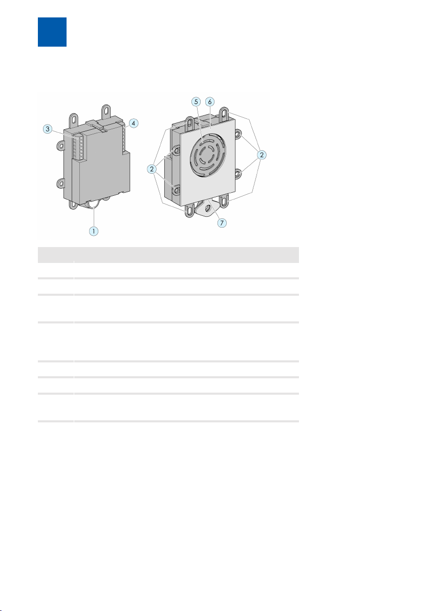
3 Product information and description
Item Description
1 Microphone (break off for split installation)
2 Securing tabs
3 Connecting terminal 1
(for bell and buttons and amplifier module)
4 Connecting terminal 2
(for voltage supply, switching contacts and telephone line)
5 Loudspeaker
6 Adhesive pad
7 Predetermined breaking point for split installation
of the microphone
6 / 52 DoorLine TM4
Page 7
Product information and description
3
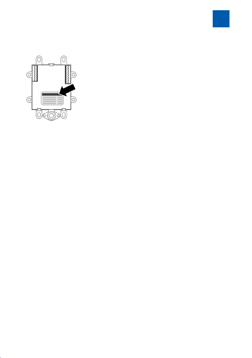
3.1 Nameplate
The nameplate contains the serial number, product coding and information on
the device type.
3.2 Specified use
DoorLine Slim is designed for connection to analogue telephone systems.
It can be used
▪ as an intercom
▪ as an electronic door opener
▪ for remote-controlled opening of doors or gates
▪ for relaying door conversations to telephones
▪ for connection to other control systems
DoorLine has been developed for private as well as commercial use.
DoorLine TM4 7 / 52
Page 8

Product information and description
3
3.2.1 Notes on the use of an electronic door opener
There is an increased risk of burglary if you connect a door opener as the relay
contacts for activation of the door opener are accessible following disassembly of the DoorLine.
An electric door opener does not substitute door closure by a locking bar, it is
an intelligent, additional safety feature.
It is primarily intended for daytime operation, whereas at night time or in case
of absence the relevant door is locked by the locking bar.
As far as insurance is concerned, a door that is held closed only by the use of
the door opener is not regarded as locked!
3.3 Technical prerequisites
▪ The device is designed for connection to an analogue telephone connec-
tion (a/b-Port) of a PBX system.
▪ Both relay switching outputs of the device connect potential-free. This
means that when a door opener or a similar device is activated, it may be
necessary to provide an additional bell transformer (see chapterConnecting device [}12]).
▪ The installation of your PBX system and its operation require the use of tele-
phone plugs (e.g. TAE or RJ11), cables and lines that are not included in the
scope of supply.
▪ Your PBX system and end devices (telephones) must support touch-tone di-
alling (DTMF).
8 / 52 DoorLine TM4
Page 9

3.4 Technical data
Product information and description
3
Telecommunication
technical data
Inputs for bell
pushbuttons
Call numbers Number per button 2call numbers with
Relay switching
outputs
General data Power supply
Dimensions Cable length, micro
Supply voltage
Supply current
Call detection
Number 4
Relay switching output
1
Relay switching output
2
Cable length
Power supply
Current consumption
Degree of protection
Operating temperature
Weight
Device
24–64VDC
20–50mA
20-50 Hz
20positions
potential-free, 24VAC /
DC1A
potential-free, 24VAC /
DC1A
9 - 24V, 0.5 A
max. 50m
Standby 0.5W
Call state max.1W
IP20
-20°C to +60°C
100g
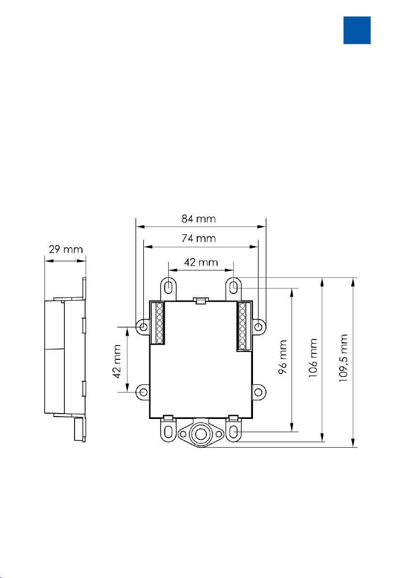
300 mm
84 x 109.5 x 29 mm
3.5 Accessories
▪ Wall power supply unit article number 114737
(For power supply to the DoorLine TM4)
▪ Wall power supply SNG DL article number 105248
(For use as bell transformer, door opener current supply, etc. Cannot be
used for power supply to the DoorLine TM4!)
▪ Power unit for carrier rail assembly (DIN rail), article number 114651 (for
voltage supply to the DoorLine TM4).
DoorLine TM4 9 / 52
Page 10

Assembly and connection
4
4
4.1
Assembly must only be carried out by specialists with corresponding skills and
experience. These persons must be able to detect dangers and to avoid possible risks.
The statutory specifications at the place of installation must be observed.
Take care not to jam the connecting cables during installation.
Also observe the safety instructions at the start of the Operating Instructions.
4.2
The scope of supply of the device includes:
▪ the device
▪ Assembly and Operating Instructions
▪ wall power supply
▪ TAE adapter
▪ Cable RJ11 to open ends
▪ 2x terminals
Assembly and connection
For your safety
Scope of supply
4.3 Prior to assembly
Check all parts for completeness and transport damage prior to assembly.
We recommend that you initially connect the DoorLine in the direct vicinity of
your PBX system, try it out and make the basic configuration.
In this manner, you can install the wiring and configure the bell pushbutton
quickly and easily.
After the DoorLine functions perfectly in this test setup with your PBX system and
telephones, you can install the DoorLine in its final place of usage.
10 / 52 DoorLine TM4
Page 11
Assembly and connection
4
4.4 Place of installation
▪ The TM4 is used for concealed installation in letterbox system with already
existing bell pushbuttons and intercom grilles.
▪ The ambient temperature must be between -20°C and +60°C.
▪ In the area of the installation location, no supply lines or similarmust be in-
stalled.
4.5 Installing device
The device is installed via the existing securing tabs or via the adhesive pad in
a letterbox system.
DoorLine TM4 11 / 52
Page 12

Assembly and connection
4
4.6 Connecting device
4.6.1 Important notes
▪ Before connecting the device to the PBX system, switch off all required
components (PBX system, device, bell transformer).
▪ When wiring, ensure that the input voltage is correct (9-24 V). The polarity
can be ignored.
▪ Do not insert the wall power supply into the socket until all cables are firmly
connected and there is no risk of a short circuit of wire pairs.
▪ A bell transformer (e.g.12 V alternating voltage) must not be used as a
power supply for the device. This can result in destruction of the device!
▪ Both integrated relay contacts connect potential-free, i.e.an additional
bell transformer is required to activate a door opener. Then connect the
bell transformer voltage via the respective relay switching output to the
door opener (see chapter Connection example for a door opener and a
door bell [}16]).
▪ Both switching relays can be loaded to a max. of 24VAC/DC1 A. Prior to
initial operation of the device, ensure that these values are not exceeded
by your door opener, door bell or other devices to be connected. Observe
the Operating Instructions of the respective products.
4.6.2 Wiring
Use commercially available telecommunication cables for the installation wiring.
Please note that in order to meet general safety provisions and to avoid interference influences, the low-current telephone lines must be routed separately
from power lines.
Observe a minimum distance of 10 cm between both types of lines. If one of
the connected lines is routed out-of-doors, you will have to provide sufficient
lightning protection.
12 / 52 DoorLine TM4
Page 13

Assembly and connection
Lines types that can be used
▪ Telecommunication indoor cable
– J-Y(ST)-Y 2 x 2 x 0.6
– J-Y(ST)-Y 2 x 2 x 0.8
– J-Y(ST)-Y 4 x 2 x 0.6
– J-Y(ST)-Y 4 x 2 x 0.8
▪ Bell sheathed cable
– YR 4 x 0.8
▪ Telecommunications cable
– A-2Y(L)2Y 4 x 2 x 0.8
Maximum cable lengths for connection to the PBX system and to the door
opener
Wire diameter 0.8 mm 0.6 mm
Ranges for voice and signal operation 320 m 140 m
Ranges for door opener operation from an external bell transformer to door opener (maximum current consumption 1A alternating
voltage)
12 V
16 V
20 V
24 V
38 m
76 m
115 m
177 m
4
17 m
34 m
51 m
78 m
Connection types
At the analogue connection of the PBX system, three connection types are
usually used in Germany:
▪ Terminals
▪ RJ 11
▪ TAE plugs
On modern PBX systems such as the AVM Fritz!Box or Telekom Speedport, the
two inner wires of the RJ 11 connection should be used.
On older PBX systems (before 2005), the two outer wires are also used.
DoorLine TM4 13 / 52
Page 14

Assembly and connection
4
4.6.3 Terminal assignment
The rear side of the device has two screw terminals.
Important: The connectors cannot be unplugged. The lines must be connected
directly to the device.
Com Common (common reference point for
the pushbutton inputs)
Button 1 – Button 4 Input for bell pushbutton
Amplifier module The loudspeaker signal for a separate
amplifier module can be tapped here
9 - 24 V DC Supply voltage (neutral polarity)
Contact 2 potential-free contact
Contact 1 potential-free contact
Telephone line The two wires for the analogue tele-
phone line are connected here
14 / 52 DoorLine TM4
Page 15
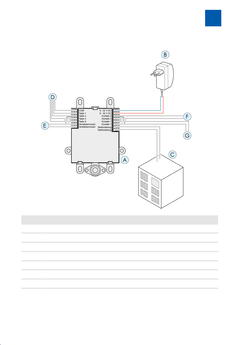
4.6.4 Wiring diagram
Assembly and connection
4
Item Description
A DoorLine TM4
B Power unit connection (neutral polarity)
C Connection to telephone system (neutral polarity)
D Inputs for bell pushbutton 1-4
E Output for amplifier module
F Output for potential-free contact 2
G Output for potential-free contact 1
DoorLine TM4 15 / 52
Page 16
Assembly and connection
4
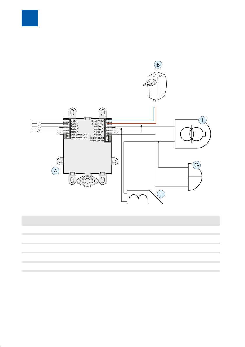
4.6.5 Connection example for a door opener and a door bell
Item Description
A DoorLine TM4
B Power unit
G Door bell at contact 1
H Door opener at contact 2
I Bell transformer
16 / 52 DoorLine TM4
Page 17

Assembly and connection
4
4.6.6 Checking connection
How to check whether installation was successful:
1. Apply the voltage supply.
ð The DoorLine starts up. After the voltage is applied, a tone sounds
(beep).
2. Call the DoorLine from a telephone that is connected to your telephone
system (see chapter Calling the DoorLine [}42]).
ð A double tone sounds in the telephone. The voice communication
between telephone and DoorLine is then built up.
If the device does not react, disconnect it immediately from the power-supply
system. Then check the connection to the power unit for a wiring fault.
If installation was successful, start the configuration of the device as described
in the following chapters.
DoorLine TM4 17 / 52
Page 18

Configuration
5
5 Configuration
5.1 Factory settings
The following parameters are preset ex works:
PIN Code 0000
Door opener function Blocked
Door opener time 3seconds
Call duration 1minute
Door call duration 30seconds
Call number bell pushbutton 1 11
Call number bell pushbutton 2 12
Call number bell pushbutton 3 13
Call number bell pushbutton 4 14
Call reception Reception by button redial
Configuration of contact 1 External gong for all bell pushbuttons
Configuration of contact 2 Door opener
Automatic door opener deactivated
Call duration after door opener deactivated
5.2 Restoring factory settings
1. Enter the configuration mode (see chapter Entry to configuration mode [}19])
2. Actuate the hashtag button and star button on the telephone
3. Enter configuration command "99" at the telephone
A melody rings out. After approx. 3 seconds you hear the
positive acknowledgement tone.
The device is now in delivery status.
18 / 52 DoorLine TM4
Page 19

Configuration
5
5.3 Acknowledgement tones
During programming, you will be informed about the positive and negative acknowledgement tones via the programming status.
Each note symbol corresponds to a beep:
neutral Key input is expected ♪
positive The programming has been accepted ♪♪
negative The programming has not been accepted ♪♪♪♪♪♪♪♪
5.4 Saving and ending configuration
To end the configuration, it is sufficient to hang up the telephone receiver. The
device then detects the end of the call automatically and saves the changed
configuration.
5.5 Information on the entry of call numbers
Input Effect
* Does not result in the selection of this character but rather a di-
alling pause of one second
** Results in one-time dialling of a "*" character
If you reach your desired telephone via the call number "**1",
you have to enter "****1" in the call number input of the DoorLine
# The DoorLine generates a flash pulse of 100ms
## Results in one-time dialling of a "#" character
5.6 Entry to configuration mode
For configuration, you have to call your DoorLine with a touch-tone dialling
telephone. The way you can call the DoorLine depends on the configuration of
your PBX system.
When the connection to the device has been established, you can start with
the configuration.
DoorLine TM4 19 / 52
Page 20

Configuration
5
Notes
▪ Write down the corresponding codes for your own reference before you
start the configuration.
▪ When the discussion duration elapses (factory setting 1 minute), the con-
nection is disconnected automatically even during programming.
▪ If the programming is rejected by the device (negative acknowledgement
tone), you will have to repeat the incorrect programming step.
▪ If you entered the wrong PIN three times in succession, the connection is dis-
connected.
1 Pick up the receiver
2 Call the device
You will hear the positive acknowledgement tone
3 Actuate the hashtag button twice on the telephone
You will hear the neutral acknowledgement tone
4 Enter the PIN
You will hear the positive acknowledgement and are now
in programming mode
If you hear the positive acknowledgement tone, you can start with the programming. Otherwise the procedure must be repeated.
If you are in programming mode, you can carry out all configuration options
one after the other.
5.7 Automatic adjustment to the PBX system
To guarantee optimum hands-free talking in all PBX systems, your device can
adjust automatically to the respective system.
The adjustment takes around 3seconds. An adjustment tone sounds during this
procedure. During this period, you should not talk into the receiver because this
can interfere with the automatic adjustment.
20 / 52 DoorLine TM4
Page 21

Configuration
We recommend that you always carry out this step after restoring
the factory settings or following a new installation.
1. Enter the configuration mode (see chapter Entry to configuration mode [}19])
2. Actuate the hashtag button and star button on the telephone
3. Enter configuration command "00" at the telephone
Wait approx. 3 seconds until the adjustment tone ends.
You will hear the acknowledgement tone.
The device is now adjusted to your PBX system
After the adjustment, you can adapt the volume and the microphone sensitivity as desired.
5
5.8 Defining microphone sensitivity and volume
The microphone sensitivity can be adjusted in 10 stages; the loudspeaker
volume in 20 stages. When the maximum or minimum possible value is
reached, you will hear an acknowledgement tone. Each correct key input is
confirmed by a neutral acknowledgement tone.
The following code numbers are possible:
Code number 2 reduces the microphone sensitivity
Code number 3 increases the microphone sensitivity
Code number 5 reduces the loudspeaker sensitivity
Code number 6 increases the loudspeaker sensitivity
DoorLine TM4 21 / 52
Page 22

Configuration
5
5.9 Change the PIN Code
In delivery status, the PIN Code for the configuration is "0000". To prevent the
settings of your DoorLine from being changed by unauthorised persons, you
should change the PIN Code as follows:
1. Enter the configuration mode (see chapter Entry to configuration mode [}19])
2. Actuate the hashtag button and star button on the telephone
3. Enter configuration command "88" at the telephone
You will hear the neutral acknowledgement tone
4. Enter new 4-digit PIN Code
You will hear the neutral acknowledgement tone
5. Repeat new PIN Code
You will hear the positive acknowledgement tone
If changing of the PIN Code is not completed with the positive acknowledgement tone, check whether the correct PIN Code was input
when you entered the configuration mode. This is not checked by the
DoorLine until the end of the complete procedure.
Changes to the configuration are only possible with knowledge of your
PIN Code. For security reasons, enter your new PIN Code in the configuration table (see Overview of programming table [}37]).
22 / 52 DoorLine TM4
Page 23

Configuration
5.10 Call numbers for bell pushbuttons
Each bell pushbutton can be assigned 2 call numbers.
With call reception by button redial, the second call number serves as an alternative number. This number is dialled if the call to the first number is not
answered or the call destination is currently busy.
With call reception in direct mode, only the first call number is selected.
5.10.1 Defining call numbers for bell pushbuttons
Configuration example: Call number 1 for bell pushbutton 1:
1. Enter the configuration mode (see chapter Entry to config-
uration mode [}19])
2. Actuate the hashtag button and star button on the tele-
phone
3. Enter configuration command for call number bell push-
button 1 "11" at the telephone
4. Neutral acknowledgement tone
5
5. Enter call number (max. 20 digits) that is to be assigned to
the bell pushbutton (see Information on the entry of call
numbers [}19])
If no input is made for 5 seconds, you will hear the acknowledgement tone and the call number will be saved
DoorLine TM4 23 / 52
Page 24

Configuration
5
The remaining call numbers are configured in the same manner. The following
commands must be used to do this:
Configuration of call number 2 for bell pushbutton 1
Configuration of call number 1 for bell pushbutton 2
Configuration of call number 2 for bell pushbutton 2
Configuration of call number 1 for bell pushbutton 3
Configuration of call number 2 for bell pushbutton 3
Configuration of call number 1 for bell pushbutton 4
Configuration of call number 2 for bell pushbutton 4
5.10.2 Deleting call numbers
You can delete a call number that is saved on a button.
Configuration example: Deleting call number 1 for bell pushbutton 1:
1. Enter the configuration mode (see chapter Entry to configuration mode [}19])
2. Actuate the hashtag button and star button on the telephone
3. Enter configuration command for call number bell pushbutton 1 "11" at the telephone
4. Neutral acknowledgement tone
5. If no input is made for 5 seconds, you will hear the positive
acknowledgement tone and the call number will be deleted
24 / 52 DoorLine TM4
Page 25

Configuration
The remaining call numbers are deleted in the same manner. The following
commands must be used to do this:
Deletion of call number 2 for bell pushbutton 1
Deletion of call number 1 for bell pushbutton 2
Deletion of call number 2 for bell pushbutton 2
Deletion of call number 1 for bell pushbutton 3
Deletion of call number 2 for bell pushbutton 3
Deletion of call number 1 for bell pushbutton 4
Deletion of call number 2 for bell pushbutton 4
5
5.11 Enabling door opener function
For security reasons to prevent unauthorised opening, the door cannot be
opened if the connection was set up from the telephone to the door intercom.
This function can be deactivated if desired.
1. Enter the configuration mode (see chapter Entry to config-
uration mode [}19])
2. Actuate the hashtag button and star button on the tele-
phone
3. Enter configuration command "04" at the telephone
As confirmation, you will hear a neutral acknowledgement
tone
4. Enter digit 1 to enable the door opener function or
digit 0 to block the door opener function
Finally, you will hear the positive acknowledgement tone
DoorLine TM4 25 / 52
Page 26

Configuration
5
5.12 Defining door opener time
Actuation time of the door opener.
Possible values: 1 to 9 seconds or deactivate with 0
Delivery status: 3 seconds
With door opening with redial #9
If relay contact2 was defined as door opener.
1. Enter the configuration mode (see Entry to configuration
mode [}19])
2. Actuate the hashtag button and star button on the tele-
phone
3. Enter configuration command "05" at the telephone
As confirmation, you will hear a neutral acknowledgement
tone
4. Define the switching time of the door opener by entering
the digits 1 to 9 (digit corresponds to the duration in
seconds, 0=deactivated)
Finally, you will hear the positive acknowledgement tone
With door opening with redial #8
If relay contact1 was defined as door opener.
1. Enter the configuration mode (see Entry to configuration
mode [}19])
2. Actuate the hashtag button and star button on the tele-
phone
3. Enter configuration command "03" at the telephone
As confirmation, you will hear a neutral acknowledgement
tone
26 / 52 DoorLine TM4
Page 27

Configuration
4. Define the switching time of the door opener by entering
the digits 1 to 9 (digit corresponds to the duration in
seconds, 0=deactivated)
Finally, you will hear the positive acknowledgement tone
5
5.13 Defining call duration
Definition of the call duration for the DoorLine.
When this time has elapsed, the door conversation is disconnected automatically.
Delivery status: one minute
Possible values: 1 to 9 minutes in steps of 1 minute or 0 for "without limitation".
1. Enter the configuration mode (see Entry to configuration
mode [}19])
2. Actuate the hashtag button and star button on the tele-
phone
3. Enter configuration command "07" at the telephone
As confirmation, you will hear a neutral acknowledgement
tone
4. Define the call duration by entering the digits 1 to 9 (digit
corresponds to the duration in minutes, 0=without limitation)
Finally, you will hear the positive acknowledgement tone
DoorLine TM4 27 / 52
Page 28

Configuration
5
5.14 Defining call duration to extension line
Definition of the duration of the door call to the extension line of your PBX system.
Delivery status: 30 seconds
Possible values: 1 to 99 seconds.
The duration of the door call to the extension line can only be adjusted
if the call reception is set to "button redial". If call reception is set to "direct mode", the setting of the call duration has no effect. When a bell
pushbutton is actuated, the set time for the call duration starts running
immediately.
1. Enter the configuration mode (see Entry to configuration
mode [}19])
2. Actuate the hashtag button and star button on the tele-
phone
3. Enter configuration command "08" at the telephone
As confirmation, you will hear a neutral acknowledgement
tone
4. Enter call duration with digits 01, ... 99 (in steps of one
second).
The input must have two digits
Finally, you will hear the acknowledgement tone
5.15 Defining type of call reception
Determines the way a call is received at the telephone after a bell pushbutton
is pressed at the DoorLine.
28 / 52 DoorLine TM4
Page 29

Configuration
5
5.15.1 Call reception by button redial
The voice connection between door intercom system and telephone is not established until the receiver has been picked up and a random digit key has
been pressed on the telephone.
1. Enter the configuration mode (see chapter Entry to configuration mode [}19])
2. Actuate the hashtag button and star button on the telephone
3. Enter configuration command "70" at the telephone
You will hear the acknowledgement tone
5.15.2 Call reception in direct mode
The voice communication between door intercom system and telephone is
built up immediately after the receiver has been picked up.
1. Enter the configuration mode (see chapter Entry to configuration mode [}19])
2. Actuate the hashtag button and star button on the telephone
3. Enter configuration command "71" at the telephone
You will hear the acknowledgement tone
DoorLine TM4 29 / 52
Page 30

Configuration
5
5.16 Preparing call forwarding
Two call numbers can be saved to which door calls can be redirected as required ("pharmacy line").
With call reception by button redial, the second call number serves as an alternative number. This number is dialled if the call to the first number is not
answered or the call destination is currently busy.
With call reception in direct mode, only the first call number is selected.
Call forwarding to these call numbers can be activated/deactivated for each
bell pushbutton as required (see chapter Activating/deactivating call forwarding [}42]).
Precondition for call forwarding to an external destination
The analogue extension line to which the DoorLine is connected must have an
authorisation for receiving external telephone calls.
In most telephone systems this function is referred to as "direct outward dialling".
5.16.1 Defining call numbers for call forwarding
1. Enter the configuration mode (see chapter Entry to configuration mode [}19])
2. Actuate the hashtag button and star button on the telephone
3. Input of the first call number: enter configuration command "51" at the telephone
or
Input of the alternative number: enter configuration command "52" at the telephone
4. Neutral acknowledgement tone
5. Enter target call number (max. 20 digits) (see Information
on the entry of call numbers [}19])
If no input is made for 5 seconds, you will hear the acknowledgement tone and the call number will be saved
30 / 52 DoorLine TM4
Page 31

Configuration
5.16.2 Deleting call numbers for call forwarding
1. Enter the configuration mode (see chapter Entry to con-
figuration mode [}19])
2. Actuate the hashtag button and star button on the tele-
phone
3. Delete the first call number: enter configuration com-
mand "51" at the telephone
or
Delete the alternative number: enter configuration command "52" at the telephone
4. Neutral acknowledgement tone
5. If no input is made for 5 seconds, you will hear the positive
acknowledgement tone and the call number will be deleted
5
DoorLine TM4 31 / 52
Page 32

Configuration
5
5.17 Configuring relay contacts
The two relay contacts can be used
▪ as a door opener or
▪ to activate a door gong.
Each contact can be assigned to one or several bell pushbuttons.
The relay contact is connected when a bell pushbutton is pressed. The contact
remains connected as long as the bell pushbutton is pressed.
5.17.1 Configuration of relay contact 1
1. Enter the configuration mode (see chapter Entry to config-
uration mode [}19])
2. Actuate the hashtag button and star button on the tele-
phone
3. Enter configuration command "61" at the telephone
Neutral acknowledgement tone
4. Enter switching command in accordance with the following
table with two digits
You will hear the acknowledgement tone as confirmation
32 / 52 DoorLine TM4
Page 33

Configuration
5
Switching
command
00 - - - - Relay contact 1 switches
01
02
03
04
05
06
07
08
09
10
Bell pushbuttons Redial Comments
1 2 3 4 #8
with redial of #8 during
voice communication
(door opener).
Factory setting
11
12
13
14
15
16 Switching contact 1 is ac-
tivated if voice communication is established.
Example: you wish to assign a door gong to relay contact 1. The door gong is
to sound when bell pushbutton2 is pushed. After entry to configuration mode,
enter the following: #à6102
DoorLine TM4 33 / 52
Page 34

Configuration
5
5.17.2 Configuration of relay contact 2
Configuration of relay contact 2
1. Enter the configuration mode (see chapter Entry to configuration mode [}19])
2. Actuate the hashtag button and star button on the telephone
3. Enter configuration command "62" at the telephone
Neutral acknowledgement tone
4. Enter switching command in accordance with the following table
You will hear the acknowledgement tone as confirmation
34 / 52 DoorLine TM4
Page 35

Configuration
5
Switching
command
00 - - - - Relay contact 2 switches
01
02
03
04
05
06
07
08
09
10
Bell pushbuttons Redial Comments
1 2 3 4 #9
with redial of #9 during
voice communication
(door opener).
Factory setting
11
12
13
14
15
16 Switching contact 2 is ac-
tivated if voice communication is established.
DoorLine TM4 35 / 52
Page 36

Configuration
5
5.18 End of call after door opening
If you wish that the connection to the door is disconnected immediately after
activation of the door opener, the option "End of call after door opening" can
be activated.
1. Enter the configuration mode (see chapter Entry to con-
figuration mode [}19])
2. Actuate the hashtag button and star button on the tele-
phone
3. Deactivated (factory setting)
activated
Neutral acknowledgement tone
36 / 52 DoorLine TM4
Page 37

Overview of programming table
6
6 Overview of programming table
The following table contains an overview of all programming commands. For
these programming commands, prior entry to configuration mode via the PIN
code is required.
When entering call numbers, note the Information on the entry of call numbers
[}19].
Programming command Own settings Description
##<PIN Code> Entry to configuration mode.
Factory setting of PIN Code:
0000
#à00 Automatic adjustment to PBX
system
#à04 <Door opener function>
#à05 <Door opener time> Switching time for door
#à07 <Call duration> Defining maximum call dura-
#à08 <Call duration> Call duration to extension line:
#à11 <Call number> Call number to be called
#à12 <Call number> Alternative number to be
#à21 <Call number> Call number to be called
Door opener function:
0=disabled
1=enabled
Factory setting: disabled
opener:
1 to 9 seconds or 0 (door
opening not possible)
Factory setting: 3 seconds
tion:
1 -9 minutes or
0=without limitation
Factory setting: 1 minute
01-99 seconds (double-digit
entry)
Factory setting: 30 seconds
from bell pushbutton 1
called from bell pushbutton 1
from bell pushbutton 2
DoorLine TM4 37 / 52
Page 38

Overview of programming table
6
Programming command Own settings Description
#à22 <Call number> Alternative number to be
called from bell pushbutton 2
#à31 <Call number> Call number to be called
from bell pushbutton 3
#à32 <Call number> Alternative number to be
called from bell pushbutton 3
#à41 <Call number> Call number to be called
from bell pushbutton 4
#à42 <Call number> Alternative number to be
called from bell pushbutton 4
#à51 <Call number> Call number to be called dur-
ing active call forwarding
#à52 <Call number> Alternative number to be
called during active call forwarding
#à61 <Command 00-16> Configuration of relay con-
tact 1. See Configuring relay
contacts [}32]
#à62 <Command 00-16> Configuration of relay con-
tact 2. See Configuring relay
contacts [}32]
#à70 Call reception by pushbutton
(factory setting)
#à71 Call reception in direct mode
#à88 <PIN><PIN> Enter new PIN Code twice
#à99 Reset to factory setting
2 Reduce microphone sensitiv-
ity
3 Increase microphone sensitiv-
ity
5 Reduce loudspeaker volume
6 Increase loudspeaker volume
38 / 52 DoorLine TM4
Page 39

Ending programming
Hang up the receiver
or enter #0.
Overview of programming table
6
DoorLine TM4 39 / 52
Page 40

Everyday use
7
7 Everyday use
7.1 Receiving a door call
A bell pushbutton at the door intercom system is pressed.
The saved call number is called.
The telephone of the called connection rings.
With presetting "Call reception by pushbutton"
1. Pick up telephone. An attention tone (beep) indicates a
call from the door intercom system
Actuate a random numeric key
Voice communication is established
2. Simply hang up the receiver to end the voice communic-
ation
or
enter digits #0 (disconnects the connection immediately)
or
the maximum call duration is reached.
The connection is then disconnected automatically
40 / 52 DoorLine TM4
Page 41

Everyday use
With presetting "Call reception in direct mode"
1. Pick up telephone
Voice communication is established directly
2. Simply hang up the receiver to end the voice communic-
ation
or
enter digits #0 (disconnects the connection immediately)
or
the maximum call duration is reached.
The connection is then disconnected automatically
7.2 Opening a door
1. A door call takes place
7
2. enter button command #8 (if relay contact1 is set as door
opener)
or
Enter button command #9 (if relay contact2 is set as door
opener)
The door opener is activated
Important:
▪ In delivery status of the DoorLine, the door cannot be opened from the tele-
phone during a call setup. If this security measure is not required, it can be
cancelled by a corresponding configuration (see chapterEnabling door
opener function [}25]).
▪ The time duration for the electric door opener can be set from 1-9 seconds
(see chapter Defining door opener time [}26]).
DoorLine TM4 41 / 52
Page 42

Everyday use
7
7.3 Calling the DoorLine
The DoorLine can also be called directly.
Setting up connection
1. Pick up telephone
2. Enter the call number of your DoorLine
You will hear the positive acknowledgement tone
Voice communication is established directly
Ending connection
1. Simply hang up the receiver to end the voice communic-
ation
or
enter digits #0 (disconnects the connection immediately)
or
the maximum call duration is reached.
The connection is then disconnected automatically
In case of loud interfering noise, it is possible that the connection is not
disconnected immediately. In this case, use option #0 to disconnect
the connection. The connection is then disconnected after the
defined time.
7.4 Activating/deactivating call forwarding
Example:
You leave the house and are expecting a parcel service or important visitor.
When you leave your house, you can now simply forward the door call to your
mobile telephone or another telephone.
42 / 52 DoorLine TM4
Page 43

Everyday use
Prerequisites:
The call numbers for call forwarding must be defined in advance (see chapter
Preparing call forwarding [}30]).
Activating call forwarding
1. Pick up telephone
2. Call the door intercom system
You will hear the acknowledgement tone
3. Press the hashtag button
4. Enter digit (1-4) for the relevant bell pushbutton
5. Enter digit 1 for activation
You will hear the acknowledgement tone. Forwarding is
active
6. Hang up the receiver
7
Deactivating call forwarding
1. Pick up telephone
2. Call the door intercom system
You will hear the acknowledgement tone
3. Press the hashtag button
4. Enter digit (1-4) for the relevant bell pushbutton
5. Enter digit 0 for deactivation
You will hear the acknowledgement tone. Forwarding is deactivated
6. Hang up the receiver
DoorLine TM4 43 / 52
Page 44

Everyday use
7
7.5 Direct commands during voice communication
During a door call, you have the following additional input options on your telephone:
Disconnects the connection immediately. DoorLine moves
to standby
Deactivate call forwarding pushbutton 1
Activate call forwarding pushbutton 1
Deactivate call forwarding pushbutton 2
Activate call forwarding pushbutton 2
Deactivate call forwarding pushbutton 3
Activate call forwarding pushbutton 3
Deactivate call forwarding pushbutton 4
Activate call forwarding pushbutton 4
Activates the door opener
or
44 / 52 DoorLine TM4
Function is only available if
▪ a relay contact is configured as door opener and
– the door call was set up by the DoorLine
or
– the door opener function was enabled in the config-
uration of the DoorLine
automatic door opening deactivated (factory setting).
automatic door opening with actuation of bell pushbutton
1, without call signalling
automatic door opening with actuation of bell pushbutton
1, with call signalling.
Page 45

Everyday use
automatic door opening with actuation of bell pushbutton
2, without call signalling.
automatic door opening with actuation of bell pushbutton
2, with call signalling.
automatic door opening with actuation of bell pushbutton
1 or 2, without call signalling.
automatic door opening with actuation of bell pushbutton
1 or 2, with call signalling.
if switching contact 2 is set as a door opener (factory setting).
if switching contact 1 is set as a door opener.
Important:
The contacts can only be switched via these direct commands if they have
been assigned the function "Redial" in the configuration.
7
DoorLine TM4 45 / 52
Page 46

Malfunctions and fault elimination
8
8 Malfunctions and fault elimination
The following table contains the most frequently occurring malfunctions and
their correction. In case of further malfunctions, please contact your specialist
dealer or our technical Hotline (see rear side of device).
No function No operating voltage Check installation.
Check Connections at
the terminals for correct
connection order.
Incorrect bell signalling
No dialling
Voice communication is
not established after
picking up the telephone
Incorrect programming
of the call numbers for
the bell pushbuttons
Call reception by button
is programmed (factory
setting)
Check programming of
buttons, repeat if necessary
Activate "Direct mode"
is desired
46 / 52 DoorLine TM4
Page 47

Maintenance, care and disposal
9
9 Maintenance, care and disposal
9.1 Storage
If the device is not installed, store it in a condensate-free area at an ambient
temperature of -20°C to +60°C.
9.2 Disassembly
Prior to disassembly of the device, de-energise all components used.
Disconnect all lines and remove the device.
9.3 Disposal
9.3.1 Disposing of packaging material
All packaging materials are environmentally compatible and recyclable. The
packaging material can be returned to the sales outlet or the local collection
centres for used paper and plastic materials.
9.3.2 Disposing of old device
The product belongs to the category electrical and electronic
equipment. In accordance with the EC Directive 2012/96/EC, it must
not be disposed of together with household waste but must be delivered to the local return system for electrical and electronic equipment.
DoorLine TM4 47 / 52
Page 48

48 / 52 DoorLine TM4
Page 49

DoorLine TM4 49 / 52
Page 50

50 / 52 DoorLine TM4
Page 51

DoorLine TM4 51 / 52
Page 52

Technical Hotline
If you have questions on the operation or configuration of your DoorLine that
cannot be answered in these Operating Instructions, please contact your specialist dealer.
If your specialist dealer cannot help, our Hotline is at your disposal.
Usage of the Hotline incurs the normal connection costs.
Telegärtner Elektronik Hotline
Tel.:
Monday-Thursday:
Friday:
+49 7951 488 9200
7:00 - 16:30 hours
7:00 - 13:00 hours
service@telegaertner-elektronik.de
Issued by / Manufacturer:
Telegärtner Elektronik GmbH
Hofäckerstraße 18
D-74564 Crailsheim
+49 7951 4880
www.telegaertner-elektronik.de
info@telegaertner-elektronik.de
Version:
1.3 / 2018/11/07
EN-Translation of the Original Operating
and Assembly Instructions
Item No.: 103021
 Loading...