

Page 1
Operating and Assembly Instructions
Door Intercom System
DoorLine Pro EXCLUSIVE
Page 2

1
Preface
1
Congratulations for purchasing the DoorLine Pro Exclusive from Telegärtner.
Read through these Operating Instructions carefully and attentively. They contain important information for your safety and valuable tips and additional application options of the device. The information on usage and care should
guarantee that you have many years of satisfaction with our product. Please
retain all documents, also for subsequent owners.
The content of these Operating Instructions has been prepared with great
care. In spite of all checks, however, there is still a possibility that technical inaccuracies and typographical errors have been overlooked. All errors that
come to our notice shall be eliminated in new editions. We highly appreciate
your feedback at any time if you find a mistake that we overlooked.
These Operating Instructions also use the term "device" or "door intercom system" to refer to the DoorLine Pro Exclusive.
The private branch exchange system is also referred to as "PBX System".
1.1
Copyright 2019 Telegärtner Elektronik GmbH
We reserve all rights to this documentation, particularly in the case of patent or
utility model applications. The documentation, or parts thereof, must not be
altered manually, or in any other manner, without the express written authorisation from us, nor translated into any other language or computer language of
any form and by any means. This applies to electronic, mechanical, optical,
chemical and all other media. Product designations and company names
used in this documentation are subject to the rights of the companies in question.
Preface
Copyright
Hofäckerstraße 18
74564 Crailsheim
2 / 112 DoorLine Pro EXCLUSIVE
Page 3

Table of contents
Table of contents
1 Preface...................................................................................................................2
1.1 Copyright ...................................................................................................2
2 Safety instructions .................................................................................................6
3 Product information and description ..................................................................7
3.1 Model variants........................................................................................... 8
3.2 Nameplate................................................................................................. 8
3.3 Specified use ............................................................................................. 9
3.3.1 Notes on the use of an electronic door opener ....................................9
3.4 Technical prerequisites........................................................................... 10
3.5 Technical data......................................................................................... 11
3.6 Configuration options .............................................................................12
3.7 Emergency PIN ........................................................................................ 13
3.8 Accessories.............................................................................................. 13
3.9 Things worth knowing about the DoorLine family ................................14
4 Assembly and connection.................................................................................15
4.1 For your safety ......................................................................................... 15
4.2 Scope of supply....................................................................................... 15
4.3 Prior to assembly .....................................................................................15
4.4 Place of installation................................................................................. 16
4.5 Installing device ......................................................................................16
4.5.1 Installing mounting plate on the wall .................................................... 16
4.5.2 Installing device on mounting plate...................................................... 17
4.6 Connecting device................................................................................. 18
4.6.1 Important notes........................................................................................ 18
4.6.2 Wiring......................................................................................................... 18
4.6.3 Terminal assignment ................................................................................20
4.6.4 Wiring diagram......................................................................................... 21
4.6.5 Connection example for a door opener and a door bell.................. 22
4.6.6 Checking connection .............................................................................23
4.7 Before initial configuration .....................................................................23
5 Configuration via the touch display..................................................................24
5.1 Navigation in the menus ........................................................................24
5.1.1 Configuration main menu....................................................................... 24
5.1.2 Submenus.................................................................................................. 25
5.1.3 Saving configuration and exiting main menu ...................................... 26
5.1.4 Use of the display keypad ...................................................................... 27
DoorLine Pro EXCLUSIVE 3 / 112
Page 4

Table of contents
5.2 Entry to the Configuration menu............................................................ 29
5.3 General settings ......................................................................................31
5.4 Bell pushbuttons ......................................................................................38
5.5 Frame lighting.......................................................................................... 43
5.6 Display brightness ...................................................................................44
5.7 Configuring relay contacts .................................................................... 45
5.8 Access control......................................................................................... 48
5.9 Acoustics.................................................................................................. 49
5.10 Acknowledgement tone ........................................................................50
5.11 Motion detectors .....................................................................................50
5.12 Date / time ............................................................................................... 51
5.13 PIN for configuration ...............................................................................52
5.14 Factory settings........................................................................................ 53
5.15 Info ............................................................................................................ 54
6 Configuration via the PC software.....................................................................55
6.1 Installing PC software.............................................................................. 55
6.2 Updating PC software ............................................................................. 58
6.3 Updating firmware................................................................................... 60
6.4 Configuring PC software......................................................................... 62
6.4.1 Reading out configuration ..................................................................... 62
6.4.2 Saving configuration ............................................................................... 65
6.4.3 Creating a backup copy........................................................................ 68
6.4.4 Information on the entry of call numbers.............................................. 69
6.4.5 Overview of the user interface............................................................... 69
6.4.6 "General" tab page ................................................................................. 71
6.4.7 "Call numbers" tab page......................................................................... 74
6.4.8 "Relay contacts" tab page .....................................................................75
6.4.9 "Appearance" tab page......................................................................... 78
6.4.10 "Bell pushbuttons" tab page ...................................................................80
6.4.11 "Access control" tab page...................................................................... 82
6.4.12 "Operating modes" tab page ................................................................ 83
6.4.13 "Door open button" tab page................................................................ 85
7 Configuration via a telephone ..........................................................................86
7.1 Acknowledgement tones....................................................................... 86
7.2 Saving and ending configuration.......................................................... 86
7.3 Information on the entry of call numbers .............................................86
7.4 Entry to configuration mode .................................................................. 86
7.5 Automatic adjustment to the PBX system............................................. 88
7.6 Restoring factory settings .......................................................................89
4 / 112 DoorLine Pro EXCLUSIVE
Page 5

Table of contents
7.7 Defining call numbers for bell pushbuttons .......................................... 89
7.8 Enabling door opener function.............................................................. 90
7.9 Defining door opener time .....................................................................91
7.10 Defining call duration.............................................................................. 92
7.11 Defining call duration to extension line ................................................93
8 Everyday use .......................................................................................................94
8.1 Receiving a door call .............................................................................94
8.2 Receiving a door call with call forwarding activated ......................... 94
8.3 Opening a door....................................................................................... 95
8.4 Using access control............................................................................... 96
8.5 Setting up call forwarding ......................................................................97
8.6 Setting up "Door open button" .............................................................100
8.7 Direct commands during voice communication ..............................103
9 Malfunctions and fault elimination..................................................................104
10 Maintenance, care and disposal....................................................................106
10.1 Cleaning................................................................................................. 106
10.2 Storage ................................................................................................... 106
10.3 Disassembly ........................................................................................... 106
10.4 Disposal .................................................................................................. 106
10.4.1 Disposing of packaging material......................................................... 106
10.4.2 Disposing of old device......................................................................... 107
11 Glossary of technical terms .............................................................................108
DoorLine Pro EXCLUSIVE 5 / 112
Page 6

Safety instructions
2
2
Before installing or using the product, it is essential to observe the instructions in
this manual.
If you fail to follow these instructions, the manufacturer Telegärtner Elektronik
GmbH will not accept any liability for any damage resulting from negligent or
deliberate disregard of the instructions in this operating manual!
▪ Keep small parts and packaging well away from children. There is a danger
▪ Connect the product only to equipment that supplies SELV (Safety Extra
▪ Only connect CE-certified end devices to the telephone system.
▪ Do not connect devices that have equipotential bonding including earth-
▪ Only use the original wall power supply of the product included in the deliv-
▪ Do not use damaged devices. Have a damaged device repaired immedi-
▪ The lines must not be installed or connected during storms. Nor is it permit-
▪ The housing must not be opened under any circumstances. Unauthorised
▪ Protect the product against dust, aggressive liquids and vapours.
▪ Do not use the product in damp rooms or in potentially explosive areas.
▪ Do not install your product near heat sources or other electrical devices.
▪ Do not permit liquid to penetrate the interior of the product. This may result
▪ Route connecting lines and cables such that there is no risk of accidents!
▪ It is essential to store the emergency PIN card separate from your door inter-
Safety instructions
of suffocation.
Low Voltage).
ing on the lines. Do not connect the a/b lines with an earthing conductor
because this can result in damage to the device.
ery.
ately.
ted to insert or unplug the connection plug during storms.
opening, incorrect repairs or modification can result in dangers to the user.
Warranty claims shall also be rendered void.
in electric shock or short-circuits.
com system.
6 / 112 DoorLine Pro EXCLUSIVE
Page 7
Product information and description
3
3
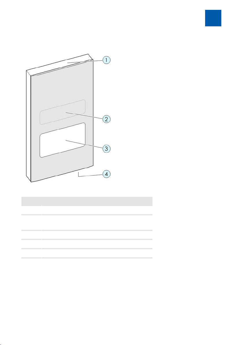
Fig.1:
Item. Description
Product information and description
1 Frame lighting
2 Motion detector (not visible)
Brightness sensor (not visible)
3 Touch display
4 Microphone
Loudspeaker (not visible)
DoorLine Pro EXCLUSIVE 7 / 112
Page 8
Product information and description
3
3.1
DoorLine Pro exclusive color
Surface Glass
Colour/Article number white 150500
DoorLine Pro exclusive steel
Surface High-grade steel
Product number 150530
3.2
Model variants
black 150510
anthracite 150520
Spot colours On request
Nameplate
The nameplate contains the serial number, product coding and additional information on the device type. The serial number is also shown on the emergency PIN card (see chapter Emergency PIN [}13]).
8 / 112 DoorLine Pro EXCLUSIVE
Page 9

Product information and description
3
3.3
DoorLine Slim is designed for connection to analogue telephone systems.
It can be used
▪ as an intercom
▪ as access control via PIN
▪ for remote-controlled opening of doors or gates
▪ for relaying door conversations to telephones
▪ for connection to other control systems
DoorLine has been developed for private as well as commercial use.
3.3.1
There is an increased risk of burglary if you connect a door opener if the relay
contacts are accessible following disassembly of the DoorLine.
It is safer to configure a door opener via a SwitchBox (accessories) because this
is located inside the house, which means that the relay contacts cannot be
manipulated from the outside.
An electric door opener does not substitute door closure by a locking bar, it is
an intelligent, additional safety feature.
It is primarily intended for daytime operation, whereas at night time or in case
of absence the relevant door is locked by the locking bar.
As far as insurance is concerned, a door that is held closed only by the use of
the door opener is not regarded as locked!
Specified use
Notes on the use of an electronic door opener
DoorLine Pro EXCLUSIVE 9 / 112
Page 10

Product information and description
3
3.4
▪ The device is designed for connection to an analogue telephone connec-
▪ The voltage is supplied via the wall power supply included in the delivery.
▪ Both relay switching outputs of the device connect potential-free. This
▪ The installation of your PBX system and its operation require the use of tele-
▪ Your PBX system and end devices (telephones) must support touch-tone di-
▪ System requirements for the PC configuration software:
Technical prerequisites
tion (a/b-Port) telephone system.
This requires a mains socket-outlet at the place of installation.
means that when a door opener or a similar device is activated, it may be
necessary to provide an additional bell transformer (see chapterConnecting device [}18]).
phone plugs (e.g. TAE or RJ11), cables and lines that are not included in the
scope of supply.
alling (DTMF).
– Pentium-compatible PC or higher
– Microsoft Windows® XP, 7, 8
– 64 MB RAM (128 MB recommended)
– 250 MB hard disc
– Minimum resolution 800x600, 256 colours
– Bluetooth interface
10 / 112 DoorLine Pro EXCLUSIVE
Page 11

Product information and description
3
3.5
Telecommunication
technical data
Display TFT
Bell pushbuttons Number 1 - 4
Call numbers Number per button 2call numbers with
Relay switching
outputs
General data Power supply
Dimensions Mounting plate
Technical data
Supply voltage
Supply current
Ringing voltage
Resolution
Relay switching
output 1
Relay switching
output 2
Input voltage
Output voltage
Cable length of wall
power supply
Current consumption
Degree of protection
Operating
temperature
Weight
Device
24 – 64VDC
20 – 50mA
32 – 75V/23 – 28Hz
42 – 75V/50Hz
4.3" touchscreen
480 x 272 pixels
25positions
potential-free, 24VAC / DC1A
potential-free, 24VAC / DC1A
via wall power supply included
in delivery
230 V AC, 50 Hz
12VDC / 1Astabilised
150 cm
10 Watt
IP54 (in installed state)
-20°C to +60°C
432 g
165 x 79.5mm
240 x 130 x 25mm (in installed
state)
DoorLine Pro EXCLUSIVE 11 / 112
Page 12

Product information and description
3
3.6
The device can be configured in three different ways.
▪ Configuration via the touch display
▪ Configuration via the PC software
▪ Configuration via a telephone
Configuration options for each configuration type
Number of bell pushbuttons X X X
Call number assignment X X X
Colour settings of bell pushbuttons X - X
Display colour/screens - - X
Display brightness X X
Screens/graphics/sounds - - X
Frame lighting X - X
Volume and microphone sensitivity X X -
Access control X - X
Time X - X
Configuration options
Touch display Telephone PC software
Recommended configuration for initial operation is the configuration via the
touch display.
As not all parameters are available in all configuration types, we recommend a
combination of the different configuration types. A background image for the
bell pushbuttons, for example, can only be loaded to the door intercom system
via the PC software.
The PC software can be downloaded in the Download area under www.telegaertner-elektronik.de.
Please note the information in the chapter Technical requirements [}10].
12 / 112 DoorLine Pro EXCLUSIVE
Page 13

Product information and description
3
3.7
An emergency PIN card is included in the scope of delivery. It includes a
device-specific emergency PIN.
If you have misplaced or forgotten your PIN for the configuration, you can reset
it at any time with the emergency PIN.
The serial number of the device is also shown on the emergency PIN card.
It is essential to store the emergency PIN card separate from your door intercom system.
3.8
To extend your door intercom system for a multi-party house or a domotics system, the following accessories are available
▪ SwitchBox SB-221
▪ SwitchBox SB-222
▪ SwitchBox SB-442
▪ I/O Box IO-332
Important: With the use of a SwitchBox SB221, no other extension boxes can be
connected to the door intercom system!
Emergency PIN
Accessories
– In-wall mounting
– 2 PBX systems, connectable
– 1 relay contact, configurable
– On-wall mounting or mounting on top hat rail
– 2 PBX systems, connectable
– 2 Relay contacts configurable
– On-wall mounting or mounting on top hat rail
– 4 PBX systems, connectable
– 3 Relay contacts configurable
– On-wall mounting or mounting on top hat rail
– 3 inputs, configurable
– 3 Relay contacts configurable
DoorLine Pro EXCLUSIVE 13 / 112
Page 14

Product information and description
3
3.9
Things worth knowing about the DoorLine family
Our DoorLine products offer optimum convenience and advantages - and the
right functions for every user. All models are developed and produced in our
headquarters in Crailsheim. Our production in Germany guarantees the very
best quality.
Commissioned by Deutsche Telekom, in 1993 the company Christoph Emmerich develops the first door intercom system which can be connected to a
telephone system. Under the brand name DoorLine, the telephone systems Eumex and T‑Concept are connected with the door intercom via a universal 2wire connection.
Four years later, Telegärtner Elektronik in Crailsheim takes over the production
of the DoorLine products. From 2003 onwards, apart from the CE2-wire version
Telegärtner also develops a new version of the DoorLine, which can be connected via the a/b‑Port and is thus compatible with all PBX systems of various
manufacturers.
Since 2003, the DoorLine is also available as a "letterbox module", i.e. without
housing and bell pushbuttons. The present-day DoorLine classic was newly developed in 2005. In 2010, a new letterbox module appears with four bell pushbuttons, door opening control and additional relay, for example, for a door
bell. The models DoorLine Pro (2014) and DoorLine Pro Exclusive (2015) are
completely new in the range.
14 / 112 DoorLine Pro EXCLUSIVE
Page 15

Assembly and connection
4
4
4.1
Assembly must only be carried out by specialists with corresponding skills and
experience. These persons must be able to detect dangers and to avoid possible risks.
The statutory specifications at the place of installation must be observed.
Take care not to jam the connecting cables during installation.
Also observe the safety instructions at the start of the Operating Instructions.
Caution: The front panel of the model DoorLine Pro exclusive color is made of
glass. It can be damaged and cause injury. Protect the glass surfaces against
damage.
4.2
The scope of supply of the device includes:
▪ the device
▪ wall power supply
▪ mounting plate
▪ bag with fastening material and Allen key
▪ brief instructions
▪ Emergency PIN card (see Emergency PIN [}13])
Assembly and connection
For your safety
Scope of supply
4.3
Check all parts for completeness and transport damage prior to assembly.
We recommend that you initially connect the DoorLine in the direct vicinity of
your PBX system, try it out and make the basic configuration.
In this manner, you can install the wiring and configure the bell pushbutton
quickly and easily.
After the DoorLine functions perfectly in this test setup with your PBX system and
telephones, you can install the DoorLine in its final place of usage.
DoorLine Pro EXCLUSIVE 15 / 112
Prior to assembly
Page 16
Assembly and connection
4
4.4
▪ The device is intended for installation outdoors in an area protected from
▪ A minimum distance from the microphone to the nearest corner wall sur-
▪ The ambient temperature must be between -20°C and +60°C.
▪ In the area of the installation location, no supply lines or similarmust be in-
4.5
The device is completely surface-mounted with the enclosed mounting plate
and fastening material.
4.5.1
Place of installation
splash water (moisture protection as per IP 54, splash water at an angle of
up to 60° to the verticals).
face of at least 10cm must be observed.
stalled.
Installing device
Installing mounting plate on the wall
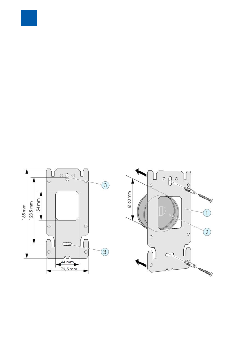
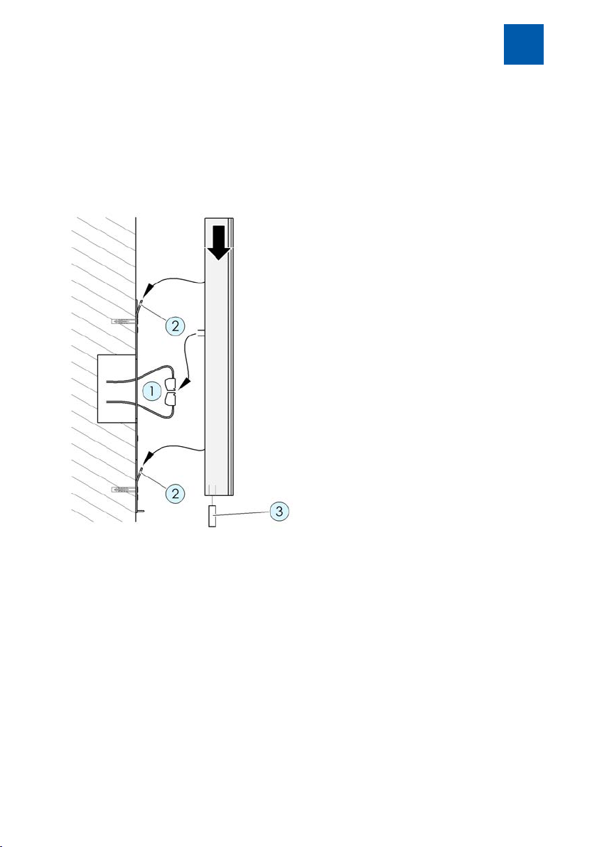
Fig.2:
1. Position the mounting plate (1) on a standard in-wall socket(2) or a suitable
cavity in the masonry. The recess in the mounting plate must be fitted accurately on the in-wall socket.
16 / 112 DoorLine Pro EXCLUSIVE
Page 17
Assembly and connection
2. Ensure that no supply lines, cables or similar are installed in the area of the
drilling holes(3).
3. Fasten the mounting plate via the two boreholes(3) onto the wall with
screwsand dowels.
4
4.5.2
Fig.3:
1. Connect the terminals(1) (see chapter Connecting device [}18]).
2. Insert the terminals (1) back into the device.
3. Place the device diagonally from above onto the mounting plate until the
4. Secure the device with the hexagon socket-grub screw(3) on the mounting
Installing device on mounting plate
four metal lugs(2) engage in the four fastening holes of the device.
plate.
Caution: Only tighten the screw lightly because otherwise the thread can
be damaged.
DoorLine Pro EXCLUSIVE 17 / 112
Page 18

Assembly and connection
4
4.6
4.6.1
▪ Before connecting the device to the PBX system, switch off all required
▪ Only use the original wall power supply included in the delivery for current
▪ When installing the wiring, ensure that the polarity (12V DC voltage) of the
▪ Do not insert the wall power supply into the socket until all cables are firmly
▪ A bell transformer (e.g.12 V alternating voltage) must not be used as a
▪ Both integrated relay contacts connect potential-free, i.e.an additional
▪ Both switching relays can be loaded to a max. of 24VAC/DC1 A. Prior to
Connecting device
Important notes
components (PBX system, device, bell transformer).
supply to the device.
two wires in the terminals is correct.
connected and there is no risk of a short circuit of wire pairs.
power supply for the device. This can result in destruction of the device!
bell transformer is required to activate a door opener. Then connect the
bell transformer voltage via the respective relay switching output to the
door opener (see chapter Connection example for a door opener and a
door bell [}22]).
initial operation of the device, ensure that these values are not exceeded
by your door opener, door bell or other devices to be connected. Observe
the Operating Instructions of the respective products.
4.6.2
Use commercially available telecommunication cables for the installation wiring.
Please note that in order to meet general safety provisions and to avoid interference influences, the low-current telephone lines must be routed separately
from power lines.
Observe a minimum distance of 10 cm between both types of lines. If one of
the connected lines is routed out-of-doors, you will have to provide sufficient
lightning protection.
18 / 112 DoorLine Pro EXCLUSIVE
Wiring
Page 19

Assembly and connection
Lines types that can be used
▪ Telecommunication indoor cable
– J-Y(ST)-Y 2 x 2 x 0.6
– J-Y(ST)-Y 2 x 2 x 0.8
– J-Y(ST)-Y 4 x 2 x 0.6
– J-Y(ST)-Y 4 x 2 x 0.8
▪ Bell sheathed cable
– YR 4 x 0.8
▪ Telecommunications cable
– A-2Y(L)2Y 4 x 2 x 0.8
Maximum cable lengths for connection to the PBX system and to the door
opener
Wire diameter 0.8 mm 0.6 mm
Ranges for voice and signal operation 320 m 140 m
Ranges for door opener operation from an external bell transformer to door opener (maximum current consumption 1A alternating
voltage)
12 V
16 V
20 V
24 V
38 m
76 m
115 m
177 m
4
17 m
34 m
51 m
78 m
Connection types
At the analogue connection of the PBX system, three connection types are
usually used in Germany:
▪ Terminals
▪ RJ 11
▪ TAE plugs
On modern PBX systems such as the AVM Fritz!Box or Telekom Speedport, the
two inner wires of the RJ 11 connection should be used.
On older PBX systems (before 2005), the two outer wires are also used.
DoorLine Pro EXCLUSIVE 19 / 112
Page 20

Assembly and connection
4
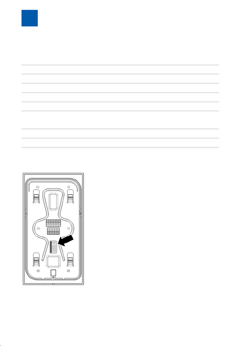
4.6.3
The rear side of the device has two screw-in/terminal plug-in connectors. They
can be unplugged for convenient connection of the lines.
Labelling is on the rear side of the casing.
View from the rear View of terminals
Terminal assignment
1 Supply voltage +12V 7 Extension box data
2 Supply voltage GND 8 Extension box -
3 Relay contact 2
potential-free
4 Relay contact 2
potential-free
5 Relay contact 1
potential-free
6 Relay contact 1
potential-free
20 / 112 DoorLine Pro EXCLUSIVE
9 Extension box +
10 Telephone line La
(independent of polarity)
11 Telephone line Lb
(independent of polarity)
Page 21
Assembly and connection
4
4.6.4
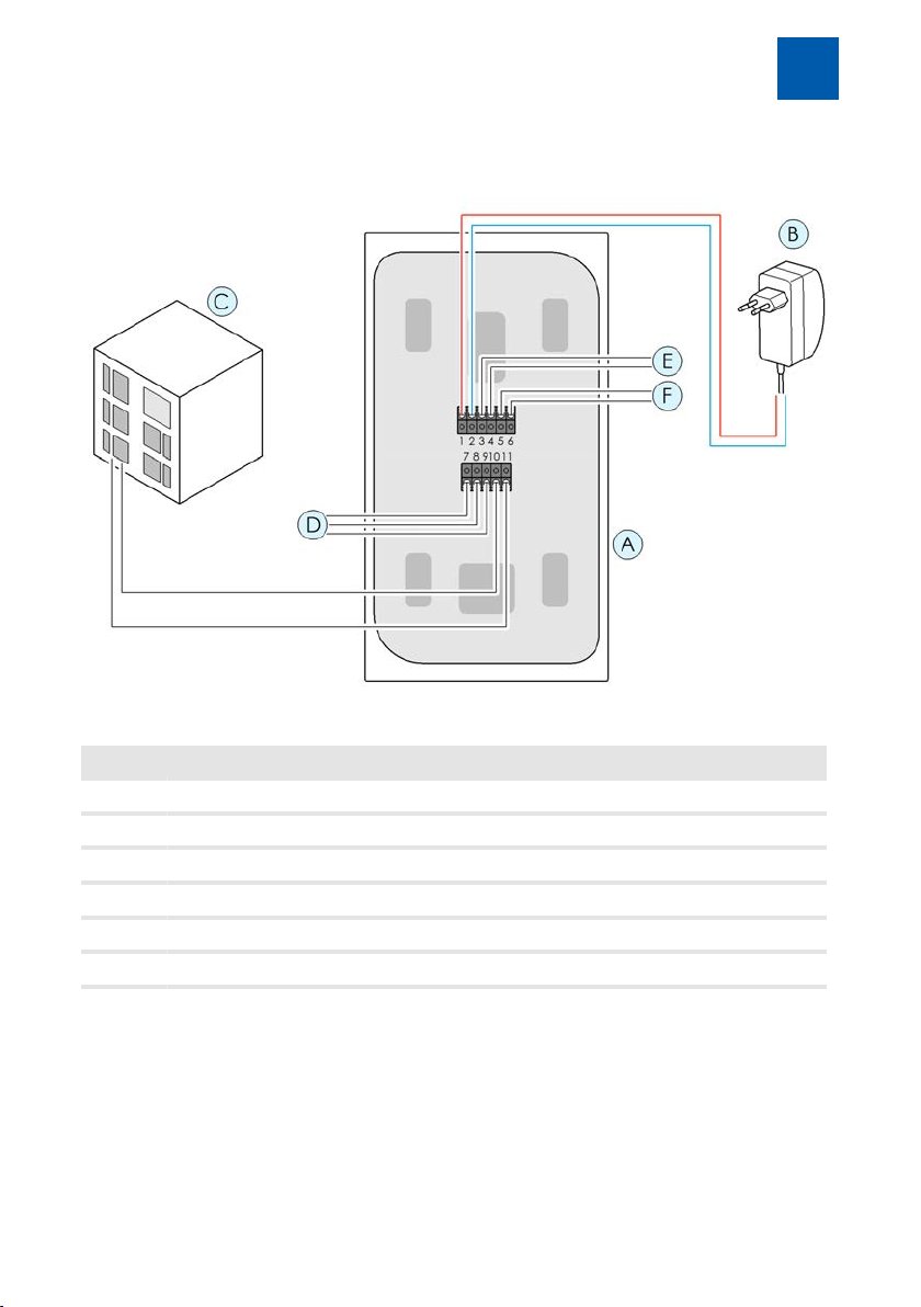
Fig.4:
Item Description
Wiring diagram
A Door intercom system (rear side of device)
B Wall power supply
C Telephone system
D Extension box
E Relay contact 2
F Relay contact 1
DoorLine Pro EXCLUSIVE 21 / 112
Page 22
Assembly and connection
4
4.6.5
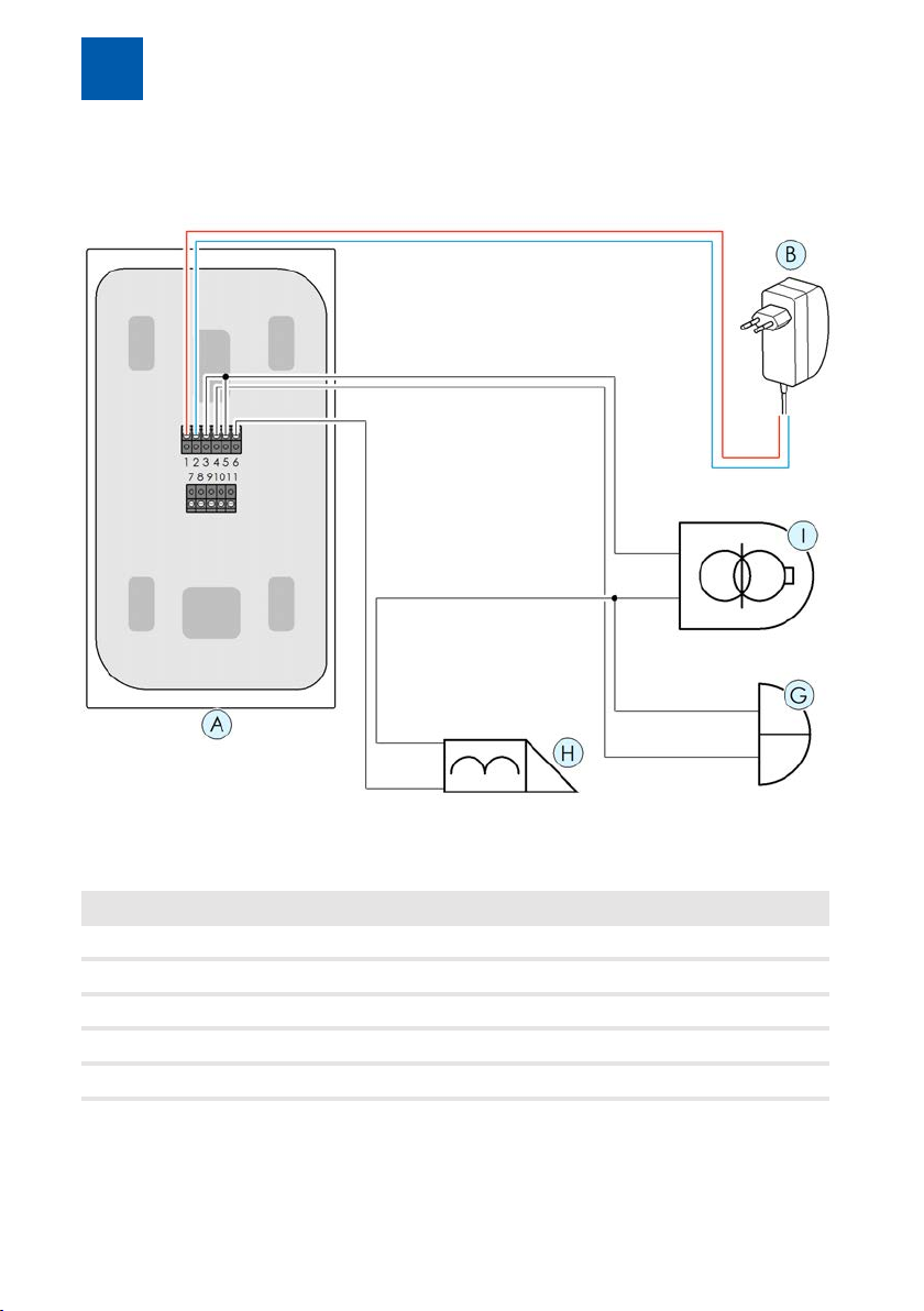
Connection example for a door opener and a door bell
Item Description
A Door intercom system (rear side of device)
B Wall power supply
G Door bell to relay contact 2
H Door opener to relay contact 1
I Bell transformer
22 / 112 DoorLine Pro EXCLUSIVE
Page 23

Assembly and connection
4
4.6.6
How to check whether installation was successful:
1. Apply the voltage supply.
Fig.5:
2. If the device does not react, disconnect it immediately from the power-sup-
If installation was successful, start the configuration of the device as described
in the following chapters.
4.7
In delivery status, the PIN code for the configuration is "0000". For security reasons, this must be changed prior to the initial configuration at the touch display
(see PIN for configuration [}52]). Configuration via the PC software is not possible prior to this.
Checking connection
ð The door intercom system starts up. The following screen content ap-
pears:
ð The frame lighting is active.
ply system. Now check the connection of terminals 1 and 2 to the wall
power supply for a wiring fault (e.g. reverse polarity of line).
Before initial configuration
DoorLine Pro EXCLUSIVE 23 / 112
Page 24
Configuration via the touch display
5
5
5.1
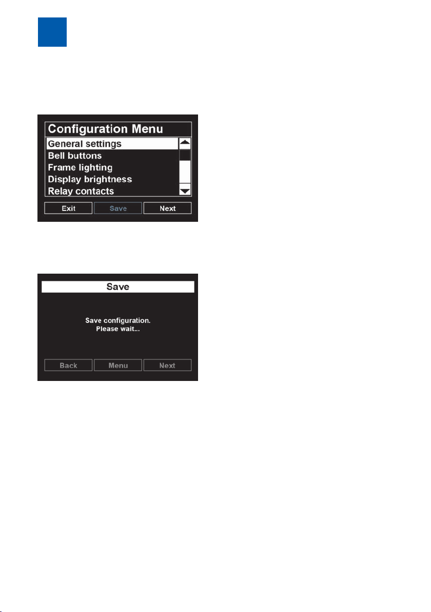
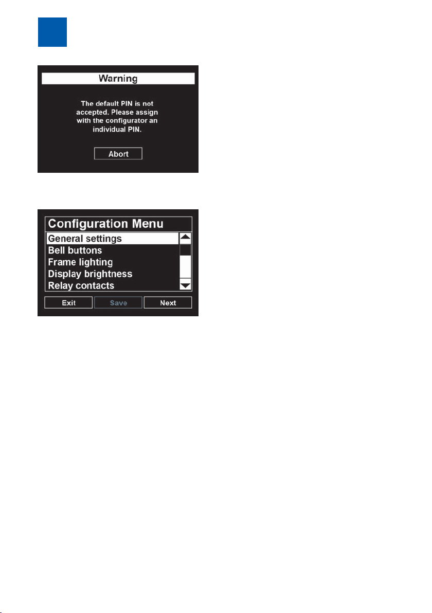
5.1.1
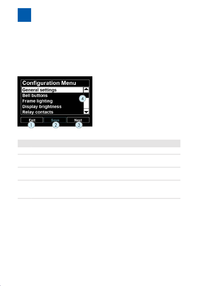
Fig.6:
Item Description
1 Press the "Exit" button to leave the Configuration menu.
2 Press the "Save" button to save all previously made changes. If there
3 The "Next" button calls up the respective marked menu or scrolls for-
4 Scrollbars scroll upwards or down in the menu.
Configuration via the touch display
Navigation in the menus
Configuration main menu
are no settings for saving, this button is not active.
ward one page within the menu.
Alternatively, the black arrows at the upper and lower end of the
scrollbar can also be used for scrolling.
24 / 112 DoorLine Pro EXCLUSIVE
Page 25
Configuration via the touch display
5
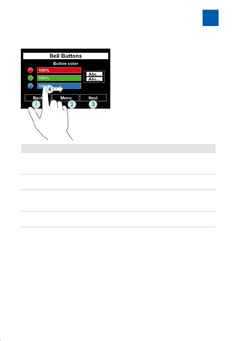
5.1.2
Item Description
Submenus
1 The "Back" button scrolls back within a Configuration page. If there
are no further pages for scrolling back, the button takes you one
menu level upwards.
3 The "Next" button calls up the next Configuration page.
If there is no further page, the button remains inactive.
2 The "Menu" button leads one menu level upward.
If this button is deactivated, the "Back" button takes you one menu
level upwards.
4 If a slider control is displayed, adjust the desired value by pulling with
your finger.
Note: Changes that you have made are not saved until you exit the configuration on the topmost level of the Configuration menu (see Configuration main
menu [}24]).
DoorLine Pro EXCLUSIVE 25 / 112
Page 26
Configuration via the touch display
5
5.1.3
Changes that were made are always saved on the topmost level of the Configuration menu.
1. After you have adapted all settings of the door intercom system as desired,
Saving configuration and exiting main menu
save the configuration with the "Save" button.
ð The following message appears during the saving process:
ð If saving is successful, the main menu is displayed again.
or
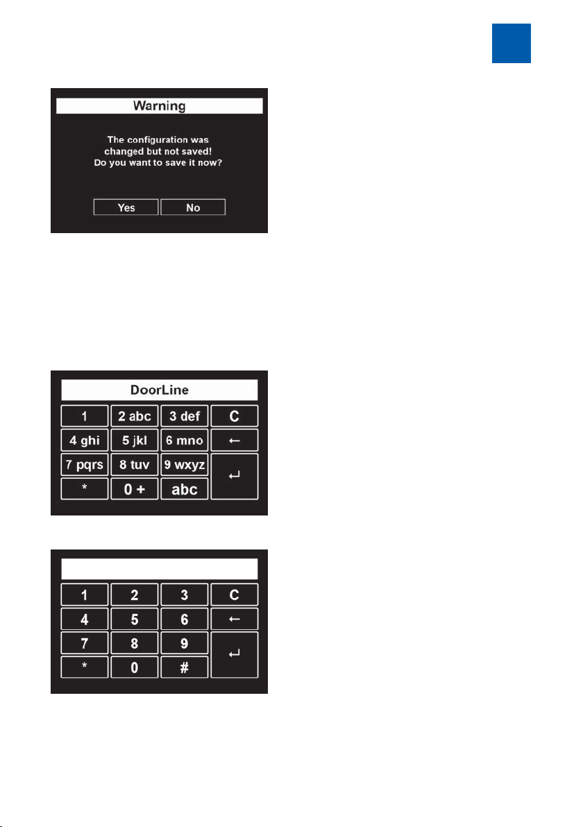
1. Leave the main menu with the "Exit" button.
ð If unsaved changes are present, the door intercom system will issue a
warning message.
26 / 112 DoorLine Pro EXCLUSIVE
Page 27
Configuration via the touch display
2. Save the changes with "Yes" or discard all changes with "No".
ð The "Bell pushbuttons" default view appears again.
5
5.1.4
A screen keypad is displayed at the relevant positions for entering digits or letters.
Fig.7: or
Use of the display keypad
DoorLine Pro EXCLUSIVE 27 / 112
Page 28

Configuration via the touch display
5
Use these buttons as follows:
C deletes the existing call number completely
← only deletes the last digit of the call number
↲ confirms the setting and leads back to the previous menu
abc or ABC switches between upper and lower case
1 inserts a blank
11 inserts the number "1"
* inserts the special characters * # ( ) [ ]
To do this, keep pressing this button until the desired character appears.
0 inserts the special characters . , ? ! ` " 0 + -
To do this, keep pressing this button until the desired character appears.
With buttons with multiple assignment, keep pressing them until the desired
character appears. This also applies to umlauts.
28 / 112 DoorLine Pro EXCLUSIVE
Page 29
Configuration via the touch display
5
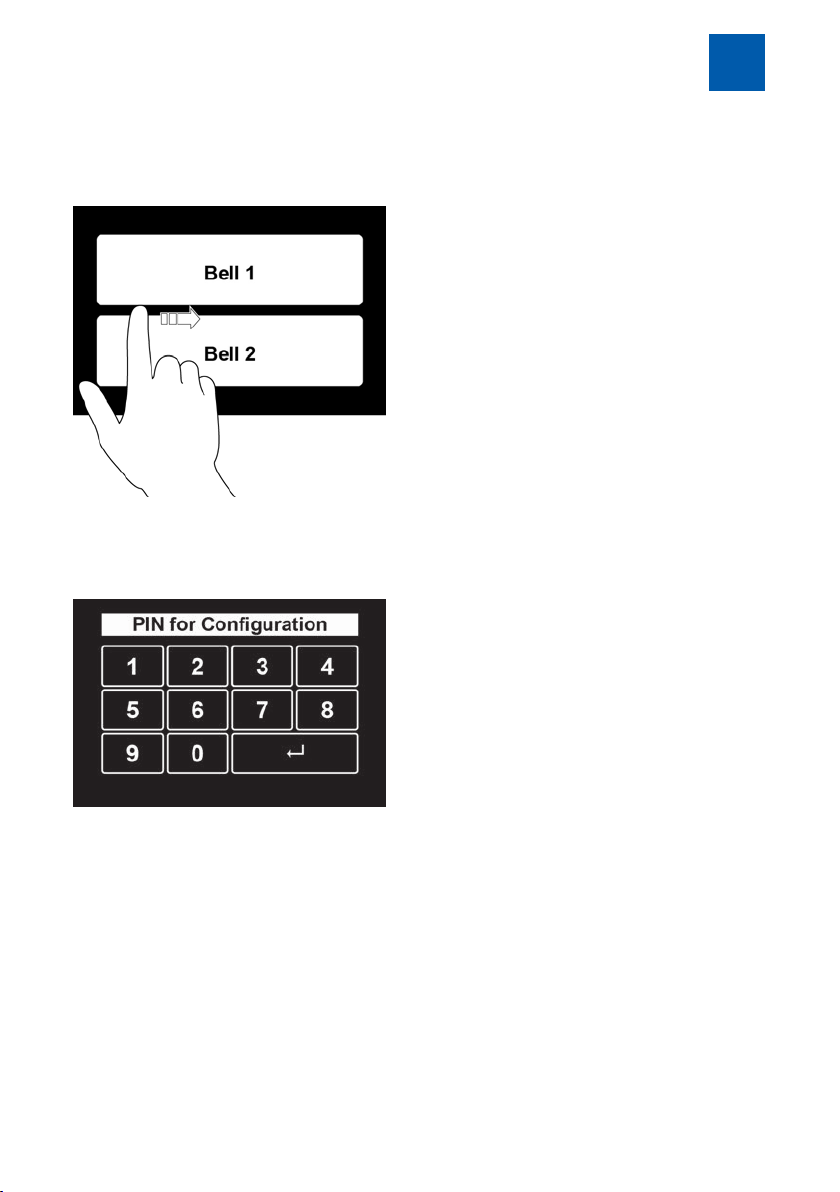
5.2
The bell pushbuttons are displayed in the basic state of the device.
1. To reach the Configuration menu, swipe your finger over the middle of the
Entry to the Configuration menu
display from the frame on the left to the right.
ð The input mask for the PIN code will then appear.
2. Enter the PIN code and press "↲" to confirm.
The PIN code ex works is "0000".
ð If no input is made, the system switches back to basic state after 30
seconds.
ð To exit PIN input immediately, swipe over the display in reverse direction.
ð If you have still not entered an individual PIN code, you will be prompted
to do so with the following message. Before doing this, you will not be
able to continue with the configuration (also refer to PIN for configuration [}52]).
DoorLine Pro EXCLUSIVE 29 / 112
Page 30
Configuration via the touch display
5
ð If the PIN has been entered correctly, you will now be in the main menu for
the configuration.
Note: If no input is made in the Configuration menu for longer than two
minutes, the menu is exited automatically and a switch is made to basic state.
30 / 112 DoorLine Pro EXCLUSIVE
Page 31

Configuration via the touch display
5
5.3
Language
Setting the display language.
German and English can currently be selected.
1. Touch the flag symbol of the desired language
ð The display language will be changed immediately.
1. Press the "Back" button to leave the menu or press the "Menu" button to
Call duration
General settings
switch to the main menu.
Definition of the call duration for the door intercom system.
When this time has elapsed, the door conversation is disconnected automatically.
1. Set the desired value with the slider control.
2. Press the "Back" button to leave the menu or press the "Menu" button to
switch to the main menu.
Delivery status: one minute
Possible values: 1 to 9 minutes in steps of one minute.
DoorLine Pro EXCLUSIVE 31 / 112
Page 32

Configuration via the touch display
5
Call duration
Definition of the duration of the door call to the extension line of your PBX system.
1. Set the desired value with the slider control.
2. Press the "Back" button to leave the menu or press the "Menu" button to
switch to the main menu.
Delivery status: 30 seconds
Possible values: 1 to 60 seconds.
Important: The duration of the door call to the extension line can only be set if
call forwarding is programmed for a bell pushbutton. If call forwarding is not
programmed, the setting of the call duration is ineffective. When a bell pushbutton is actuated, the set time for the call duration starts running immediately.
Activation duration
The activation duration defines how long after detection of a movement by
the integrated motion detector the bell pushbuttons remain faded in and the
lighting remains activated.
1. Set the desired value with the slider control.
2. Press the "Back" button to leave the menu or press the "Menu" button to
switch to the main menu.
32 / 112 DoorLine Pro EXCLUSIVE
Page 33

Configuration via the touch display
Possible values: 1 to 120 seconds
The value 0 results in permanent activation of the device.
Door opener function
For security reasons to prevent unauthorised opening, the door cannot be
opened if the connection was set up from the telephone to the door intercom
system. This function can be deactivated if desired.
1. Set the desired selection by touching the respective option.
2. Press the "Back" button to leave the menu or press the "Menu" button to
switch to the main menu.
Observe the Notes on the use of an electronic door opener [}9].
5
Door opener time
Actuation time of the door opener.
Possible values: 1 to 9 seconds
1. Set the desired value with the slider control.
2. Press the "Back" button to leave the menu or press the "Menu" button to
switch to the main menu.
DoorLine Pro EXCLUSIVE 33 / 112
Page 34

Configuration via the touch display
5
SwitchBox
Selection of the type of SwitchBox (optional) installed on your system. For security reasons, communication between the door intercom system and the
SwitchBox is protected by a PIN code. Without the correct PIN code, the
SwitchBox has no function. For more information on the connection of the
SwitchBox, please refer to the operating instructions of the corresponding box.
1. Select the matching type by touching the corresponding option and press
"Next" to confirm.
2. Touch the grey input field under "Current PIN" to display the current PIN. The
PIN code ex works is "0000".
ð A keypad appears on the touch display (see Use of the display keypad
[}27]).
34 / 112 DoorLine Pro EXCLUSIVE
Page 35

Configuration via the touch display
3. Enter the current PIN code and press "↲" to confirm.
4. Touch the grey input field under "New PIN" to enter a new PIN code.
ð A keypad appears on the touch display
5. Enter a 4- to 12-digit PIN. "0000" is not accepted for security reasons. The
new PIN code must also be entered if it was not changed.
6. To save the new PIN code, press the "Back" button to leave the menu or
press the "Menu" button to switch to the main menu. Save the configuration
here with the "Save" button.
ð If you have entered an incorrect current PIN code, or selected a Switch-
Box other than the connected one, or connected the SwitchBox incorrectly, the following fault message appears:
5
ð If you have connected a SwitchBox and an I/O Box and made incorrect
input for both or made an incorrect connection, the following fault message appears:
DoorLine Pro EXCLUSIVE 35 / 112
Page 36

Configuration via the touch display
5
I/O Box
Selection of the type of I/O Box (optional) installed on your system. For security
reasons, communication between the door intercom system and the I/O Box is
protected by a PIN code. Without the correct PIN code, the I/O Box has no
function. For more information on the connection of the I/O Box, please refer to
the operating instructions of the corresponding box.
1. Select the matching type by touching the corresponding option and press
"Next" to confirm.
2. Touch the grey input field under "Current PIN" to display the current PIN. The
PIN code ex works is "0000".
ð A keypad appears on the touch display (see Use of the display keypad
[}27]).
36 / 112 DoorLine Pro EXCLUSIVE
Page 37

Configuration via the touch display
3. Enter the current PIN code and press "↲" to confirm.
4. Touch the grey input field under "New PIN" to enter a new PIN code.
ð A keypad appears on the touch display
5. Enter a 4-to12-digit PIN. "0000" is not accepted for security reasons. The
new PIN code must also be entered if it was not changed.
6. To save the new PIN code, press the "Back" button to leave the menu or
press the "Menu" button to switch to the main menu. Save the configuration
here with the "Save" button.
ð If you have entered an incorrect current PIN code, or selected an
I/O-Box other than the connected one, or connected the I/O Box, the
following fault message appears:
5
ð If you have connected a SwitchBox and an I/O Box and made incorrect
input for both or made an incorrect connection, the following fault message appears:
DoorLine Pro EXCLUSIVE 37 / 112
Page 38

Configuration via the touch display
5
5.4
In the "Bell pushbuttons" menu, you can make the following basic settings for
the bell pushbuttons.
▪ Number of bell pushbuttons
▪ Call number assignment of the bell pushbuttons
▪ Lettering of the bell pushbuttons
▪ Colour of the bell pushbuttons
▪ Background colour of the bell pushbuttons
▪ Ring tone at loudspeaker of door intercom system
You will be guided by a wizard through all necessary configuration pages.
Please keep a list of the call numbers ready in advance that are to be called
when a bell pushbutton is pressed.
Bell pushbuttons
Ensure that the colour contrast between the button colour and the lettering colour is high enough (light-coloured background, black foreground) that the lettering is easily legible.
Call groups:
Depending on the telephone system you are using, several telephones
can also be called with a single button if you set up one or several call
groups in your telephone system.
If a call group is used, the group call number defined in the telephone
system is entered in the door intercom system. When this group call
number is selected, all end devices that are assigned to this call group
ring.
Collective call:
Alternatively, many telephone systems also support a "collective call".
With a collective call, however, all end devices connected to a telephone system are called. A restriction to individual telephones is not
possible in this case.
Please refer to the respective operating instructions to determine
whether your telephone system supports the collective or group call
function.
38 / 112 DoorLine Pro EXCLUSIVE
Page 39

Configuration via the touch display
Configuring bell pushbutton
1. In the Configuration menu, select the item "Bell pushbuttons".
ð The following view appears:
2. Select how many bell pushbuttons are to be shown on the display and press
"Next" to confirm.
5
3. Select the background colour of the "Bell pushbutton" default view. To do
this, drag the colour slider control into the desired position.
ð A preview of the settings is shown on the right side of the touch display.
4. Press "Next" to confirm your settings.
DoorLine Pro EXCLUSIVE 39 / 112
Page 40

Configuration via the touch display
5
Fig.8:
5. Set the colour of the bell pushbutton with the colour slider control.
ð A preview of the settings is shown on the right side of the touch display.
6. Press "Next" to confirm your settings.
7. Set the colour of the of the bell pushbutton lettering with the colour slider
control.
ð A preview of the settings is shown on the right side of the touch display
8. Press "Next" to confirm your settings.
40 / 112 DoorLine Pro EXCLUSIVE
Page 41

Configuration via the touch display
9. Touch the grey field under "Call number 1" to enter the main call number.
ð A keypad appears on the touch display.
10. Enter the main call number that is to be assigned to the bell pushbutton 1
(see Use of the display keypad [}27]).
11. Press "↲" to confirm the settings.
ð This takes you back to the previous menu.
12. If you wish to create call forwarding for this bell pushbutton, touch the grey
field under "Call number 2" and enter the call number via the display
keypad to which the discussion is to be redirected in case of call forwarding.
13. After you have entered the call numbers, press "Next" to confirm.
5
14. To provide visitors with feedback after actuation of a bell pushbutton, set
"Ring tone with button actuation" to "on". Every time a button is actuated,
the door intercom system now plays an information tone via the loudspeaker.
15. Touch the grey field under "Button lettering" to enter the lettering for the bell
pushbutton.
ð A keypad appears on the touch display.
DoorLine Pro EXCLUSIVE 41 / 112
Page 42

Configuration via the touch display
5
16. Enter the lettering for the bell pushbutton (see Use of the display keypad
[}27]).
17. Press "↲" to confirm your input.
ð If you have selected a SwitchBox installed in your system under "General
settings" – "SwitchBox", the Configuration menu for the SwitchBox now
appears. Depending on the type used, you can reach up to 4 users (residential units with different telephone systems) via the SwitchBox.
18. Now select the user who is to be reached with the bell pushbutton via the
SwitchBox.
ð Programming for the first bell pushbutton is now complete.
ð If you have selected more than one bell pushbutton at the start of the bell
pushbutton configuration, the assignment of the call numbers now takes
place with the lettering of these bell pushbuttons. Proceed in the same
manner as with the first bell pushbutton.
42 / 112 DoorLine Pro EXCLUSIVE
Page 43

Configuration via the touch display
5
5.5
The lighting of the frame of the door intercom system can be set in three different ways:
Colour change
In "Colour change" mode, the possible colours are presented one after the
other.
1. Select "Colour change" and confirm with "Next" to adapt the brightness and
Frame lighting
speed of the frame lighting.
2. Set the desired values by dragging the slider control.
3. Exit the menu with the "Menu" button.
Monocolour
In "Monocolour" mode, the frame colour can be adapted individually.
1. Select "Monocolour" and confirm with "Next" to set the colour of the frame
lighting.
DoorLine Pro EXCLUSIVE 43 / 112
Page 44

Configuration via the touch display
5
2. Set the desired values by dragging the slider control.
3. Exit the menu with the "Menu" button.
Off
In "Off" mode, the frame lighting is deactivated.
5.6
The background lighting of the display can be adapted via the "Display brightness" menu.
If automatic brightness control is activated, the door intercom system selects
the optimum brightness depending on ambient light. The maximum possible
brightness is set via the slider control.
1. Set the desired values by dragging the slider control.
2. Select "Automatic brightness control" if the brightness of the display lighting
3. Exit the menu with the "Back" button.
Display brightness
is to adapt to the ambient brightness.
44 / 112 DoorLine Pro EXCLUSIVE
Page 45

Configuration via the touch display
5
5.7
The basic configuration of the door intercom system offers you two potentialfree relay contacts that can be used in a wide variety of ways. Additional relay
contacts provide you with the optional SwitchBoxes and the optional I/O Box.
Important: With the use of a SwitchBox SB221, no other extension boxes can be
connected to the door intercom system!
Application options
Bell pushbuttons All relay contacts can be assigned bell pushbuttons,
Motion detectors Relay contact is activated when the door intercom
Redial In order to perform other switching functions with the
Door opener The relay contact switches with redialling digits #9. In
Configuring relay contacts
for example, for additional activation of a normal
door gong during a ringing operation. It is also conceivable here to activate a light or to cut in another
device (important: observe max. breaking capacity
of the switching relay; it may be necessary to use a
power relay).
system detects a movement via the motion detector.
door intercom system, an option is also provided for
remote control of the switching relays via redialling
commands from a telephone. This function is helpful
for remote switching of a very wide variety of devices
in the building. The relay contacts can be switched
via a call to the door intercom system and redialling
of the following digits:
#1 = relay contact 1
#2 = relay contact 2
#3 = relay contact 1 SwitchBox (optional)
#4 = relay contact 2 SwitchBox (optional)
#5 = relay contact 3 SwitchBox (optional)
#6 = relay contact 1 I/O Box (optional)
#7 = relay contact 2 I/O Box (optional)
#8 = relay contact 3 I/O Box (optional)
the ex-works setting of the door intercom system, the
contact can only be switched if the call is made from
the door intercom system (see chapter Opening a
door [}95]).
DoorLine Pro EXCLUSIVE 45 / 112
Page 46

Configuration via the touch display
5
Configuration of the relay contacts
1. In the Configuration menu, select the item "Relay contacts".
ð The following view appears:
2. Select the desired usage for relay contact 1.
3. If you assigned contact 1 to a motion detector, you can activate a light
sensor. With the light sensor activated, the relay contact is only activated if
the surrounding area is dark.
4. If you assigned contact 1 to a bell pushbutton, then actuate the "Button selection" button.
5. Define which bell pushbutton activates contact1. Only activated bell pushbuttons can be selected.
6. Press "OK" to confirm
ð This takes you back to the "Contact1" menu.
7. Press "Next" to confirm.
ð This takes you to the Configuration menu for "Contact2".
8. For "Contact2", process in the same manner as for "Contact1".
ð If no SwitchBox and no I/O Box are connected, the configuration of the
relay contacts is now complete. Press the "Menu" button to return to the
main menu.
46 / 112 DoorLine Pro EXCLUSIVE
Page 47

Configuration via the touch display
ð If you have connected an optional SwitchBox and logged it in, actu-
ation of the "Next" button takes you to the next menu.
9. Proceed in the same manner as for "Contact 1" for "SwitchBox contact1",
"SwitchBox contact2" and "SwitchBox contact3".
ð If no I/O Box is connected, the configuration of the relay contacts is now
complete. Press the "Menu" button to return to the main menu.
ð If you have connected an optional I/O-Box and logged in it, actuation
of the "Next" button takes you to the next menu.
5
10. Proceed in the same manner as for "Contact 1" for "I/O Box contact1",
"I/O Box contact2" and "I/O Box contact3".
DoorLine Pro EXCLUSIVE 47 / 112
Page 48

Configuration via the touch display
5
5.8
You can use the door intercom system for keyless door opening by means of a
number code (see chapter Using access control [}96]).
In order to use the access control, at least one relay contact must be configured as a door opener!
1. In the Configuration menu, select the item "Access control".
2. Activate or deactivate the access control by touching "on" or "off".
3. Touch the grey input field under "New PIN" to enter a PIN code.
Access control
ð The following view appears:
ð A keypad appears on the touch display.
4. Enter a 4- to 12-digit PIN, with which the door is subsequently opened (see
Use of the display keypad [}27]).
ð For security reasons, the entered PIN is not displayed in the white control
field as a number but only as "*".
5. Press "↲" to confirm your input.
Important: A PIN is provided for access control and a further PIN number for the
configuration of the door intercom system!
48 / 112 DoorLine Pro EXCLUSIVE
Page 49

Configuration via the touch display
5
5.9
Make the audio settings of the door intercom system in the "Acoustics" menu.
The loudspeaker can be adjusted in 32 levels; the microphone sensitivity in 4
levels.
1. Set the desired value for the loudspeaker volume with the upper slider con-
2. Set the desired value for the microphone sensitivity with the lower slider con-
3. Exit the menu with the "Back" button.
Important: If the setting for the microphone sensitivity or loudspeaker volume is
too high, this can result in acoustic feedback in the form of unpleasant whistling sounds. In this case, reduce the volume of the loudspeaker and the sensitivity of the microphone until the acoustic feedback has disappeared. Before
making the volume setting, always carry out automatic calibration to the telephone system (see chapter Automatic adjustment to the PBX system [}88]).
Acoustics
trol.
trol.
DoorLine Pro EXCLUSIVE 49 / 112
Page 50

Configuration via the touch display
5
5.10
Acknowledgement tone
Setting of the volume of the acknowledgement tone that is played on the door
intercom system.
1. Select the desired volume by touching the respective option.
2. Check your settings with the "Test" button.
3. Exit the menu with the "Menu" button.
5.11
In the "Motion detector" menu, set the sensitivity of the motion detector that is
integrated in the door intercom system.
The setting from 10‑100% corresponds to an approximate range of
2‑4metres distance, depending on the environment, shading or external influences.
The motion detector activates the door intercom system as soon as a movement from the front is registered. The door intercom system remains active for
the time that was set in the "Activation duration" menu.
A relay contact can also be assigned to the motion detector, for example, in
order to activate lighting or a camera.
Acknowledgement tone
Motion detectors
50 / 112 DoorLine Pro EXCLUSIVE
Page 51

Configuration via the touch display
1. Set the desired value by dragging the slider control.
2. Exit the menu with the "Back" button.
5
5.12
In order to support day- or time-dependent functions, set the current date and
time in the "Date / time" menu.
1. Select the parameters to be set by touching them in the topmost line
2. Set the desired value by dragging the slider control.
3. Press "OK " to confirm your settings.
Date / time
(Year / Month / Day or Hour / Minutes / Seconds).
ð The selected parameter is displayed above the slider control.
ð The selected value is displayed on the slider control. Furthermore, the
parameter in the topmost line displays the currently set value.
DoorLine Pro EXCLUSIVE 51 / 112
Page 52

Configuration via the touch display
5
5.13
To protect the settings of your door intercom system against unauthorised access, you have to enter a separate PIN. In delivery status, the PIN is set at "0000".
If the PIN of your device is no longer set at "0000" (delivery state) and you no
longer know the changed PIN, then use the emergency PIN to reset the PIN for
the configuration (see chapter Emergency PIN [}13]).
1. To define an access code (PIN), touch the grey input field below "Define
PIN for configuration
new PIN".
ð A keypad appears on the touch display.
2. Enter a 4- to 12-digit PIN, with which you can subsequently reach the Configuration menu (see Use of the display keypad [}27]). "0000" is not accepted for security reasons.
3. Press "↲" to confirm your input.
ð For security reasons, the entered PIN is not displayed in the white control
field as a number but only as "*".
52 / 112 DoorLine Pro EXCLUSIVE
Page 53

Configuration via the touch display
5
5.14
If you are no longer satisfied with the settings of your door intercom system or
you have made a mistake during the configuration, you can restore the delivery state of your door intercom system via the "Factory settings" menu.
1. Start the recovery of the factory settings with the "Yes" button.
Factory settings
Press the "No" button to exit the "Factory settings" again. You are now back
in the main menu.
ð The restoration of the delivery state now starts immediately and without
further prompting.
ð After the factory setting has been restored, the door intercom system re-
starts.
DoorLine Pro EXCLUSIVE 53 / 112
Page 54

Configuration via the touch display
5
5.15
The Info menu (illustration is an example), shows you the following information
on your door intercom system:
▪ Type designation
▪ Software version
▪ Date
▪ Time
▪ Bluetooth address
▪ Bluetooth name
The information shown here can be useful when making contact with Customer Support of Telegärtner Elektronik GmbH or during configuration via the
PC software.
Info
54 / 112 DoorLine Pro EXCLUSIVE
Page 55

Configuration via the PC software
6
6
6.1
1. Under http://www.doorlinepro.de/de/support/fuer-doorline-pro/doorline-
2. Start the installation procedure by double-clicking on the file
3. Confirm the message with "Yes".
4. Now follow the instructions of the installation software.
Configuration via the PC software
Installing PC software
pro-handbuecher-downloads.html, download the current version of the
software and save the file on your PC under the name
<<dp100setup.exe>>.
<<dp100setup.exe>>.
ð The following warning message is issued:
5. Select the language and press "Next" to confirm.
DoorLine Pro EXCLUSIVE 55 / 112
Page 56

Configuration via the PC software
6
6. Press "Next" to continue.
7. Select the target folder for the installation and press "Next" to continue.
8. Select the start menu folder for the program link and press "Next" to continue.
56 / 112 DoorLine Pro EXCLUSIVE
Page 57

9. Press "Next" to confirm.
Configuration via the PC software
6
10. Check your settings and press "Next" to confirm.
11. End the installation procedure with "Finish".
ð After completion of the installation procedure, the configuration software of
the device is started.
DoorLine Pro EXCLUSIVE 57 / 112
Page 58

Configuration via the PC software
6
6.2
To ensure that the latest version of the PC configurator is always used, activate
the option "Check for updates" in the "Settings" menu of the PC software.
After the PC software has started, an automatic check determines whether a
newer version is available. If a newer version is available, the following screen
mask appears:
Updating PC software
1. Press "Yes" to confirm if you wish to download and install the current version.
58 / 112 DoorLine Pro EXCLUSIVE
Page 59

Configuration via the PC software
2. Select the storage location for the installation program and press "Save" to
confirm.
ð The download procedure is now started.
3. After completion of the download procedure, the following message is issued:
6
4. Close the window with the "x" symbol in the top right of the window.
5. End the PC software.
6. Unpack the downloaded "Zip" file (double-click on the file).
7. Install the software as described in the chapter "Installing PC software [}55]"
by executing the file <<dp100setup.exe>> contained in the Zip file.
DoorLine Pro EXCLUSIVE 59 / 112
Page 60

Configuration via the PC software
6
6.3
After the door intercom system is read out for the first time, an automatic
check determines whether a newer version of the device firmware is available.
If a newer version is available, the following screen mask appears:
1. Press "Yes" to confirm if you wish to download and install the current version.
Updating firmware
2. Save the update file in the suggested folder.
ð The download procedure is now started.
60 / 112 DoorLine Pro EXCLUSIVE
Page 61

Configuration via the PC software
3. After completion of the download procedure, the following message is issued:
6
4. Close the window via the "x" symbol in the top right of the window.
5. Save the current configuration of your door intercom system (see Saving
configuration [}65]).
6. Import the downloaded file to your door intercom system via the menu "Execute" "Firmware Update".
DoorLine Pro EXCLUSIVE 61 / 112
Page 62

Configuration via the PC software
6
6.4
Before a configuration can be adapted via the PC software, you have to import the current version of the configuration from the door intercom system into
the PC software (see chapter Reading out configuration [}62])
After you have adapted the configuration via the PC software, transfer it to the
door intercom system (see chapter Saving configuration [}65]).
6.4.1
When you read out the configuration for the first time, you require the
Bluetooth address of your door intercom system. You can find this on your
emergency PIN card or in the Info menu of your door intercom system (see
chapter Info [}54]).
Proceed as follows to read out a configuration saved in the door intercom system:
1. Click in the menu bar of the PC configurator on "Device type" and select
2. Ensure that your door intercom system displays the default view "Bell push-
Configuring PC software
Reading out configuration
which model variant you wish to adapt.
buttons". If a menu is active on the door intercom system, transfer to the PC
configurator is blocked.
3. In the PC configurator, click on the "Read out" button.
ð The following mask then appears:
62 / 112 DoorLine Pro EXCLUSIVE
Page 63

Configuration via the PC software
ð The configurator now searches through all Bluetooth devices in the envir-
onment. This procedure can take up to 2minutes depending on how
many Bluetooth devices there are in the range of the PC.
ð When you call up the configuration for the first time, the following screen
mask appears:
6
DoorLine Pro EXCLUSIVE 63 / 112
Page 64

Configuration via the PC software
6
4. Select the Bluetooth address of the desired door intercom system.
5. Now enter your PIN (input required only once per session).
ð After the import is complete, the following screen mask appears:
64 / 112 DoorLine Pro EXCLUSIVE
Page 65

Configuration via the PC software
ð The read-out configuration can now be processed or saved to back up the
data.
ð After the door intercom system is read out for the first time, an automatic
check determines whether a newer version of the device firmware is available (see Updating firmware [}60]).
We recommend that you always back up a created configuration of
the door intercom system via the "Read out and save function" of the
PC configurator irrespective of whether this was created via the touch
display, the telephone or via the PC configurator. A created configuration can thus be installed at any time back into the door intercom
system.
6
6.4.2
After you have adapted all settings for the door intercom system as desired,
the configuration must still be transferred to the door intercom system.
1. Ensure that your door intercom system displays the default view "Bell push-
2. In the PC configurator, click on the "Program" button.
Saving configuration
buttons". If a menu is active on the door intercom system, transfer from the
PC configurator to the door intercom system is blocked.
ð The following mask then appears:
DoorLine Pro EXCLUSIVE 65 / 112
Page 66

Configuration via the PC software
6
ð The PC configurator now searches for all Bluetooth devices in the envir-
onment. This procedure can take up to 2minutes depending on how
many Bluetooth devices there are in the range of the PC.
ð If several door intercom systems are found in the environment, the fol-
lowing screen mask appears:
66 / 112 DoorLine Pro EXCLUSIVE
Page 67

Configuration via the PC software
3. Select the door intercom system to which the configuration is to be transferred.
Note: the indicated device name can be displayed via the touch display of
the door intercom system under the menu item "Info" (see chapter Info
[}54]).
ð If the correct door intercom system was selected, the following screen
mask appears:
6
4. Now enter your PIN (input required only once per session).
ð After a successful transfer of the configuration to the door intercom sys-
tem, the following screen mask appears:
DoorLine Pro EXCLUSIVE 67 / 112
Page 68

Configuration via the PC software
6
ð The touch display of the door intercom system signals that the configura-
tion is saved.
Your door intercom system is not fully set up.
6.4.3
Back up the configuration you have made by saving it on the PC via the menu
"File – Saver" (see chapter Overview of the user interface [}69]).
A configuration backed up in this manner can be restored at any time via the
menu "File – Open".
68 / 112 DoorLine Pro EXCLUSIVE
Creating a backup copy
Page 69

Configuration via the PC software
6
6.4.4
Input Effect
* Does not result in the selection of this character but rather a di-
** Results in one-time dialling of a "*" character
# The DoorLine generates a flash pulse of 100ms
## Results in one-time dialling of a "#" character
6.4.5
Information on the entry of call numbers
alling pause of one second
If you reach your desired telephone via the call number "**1",
you have to enter "****1" in the call number input of the DoorLine
Overview of the user interface
Menu bar (1)
File New Starts a new configuration.
Open Opens a saved configuration.
Save Saves a configuration on the PC.
Exit Ends the software.
DoorLine Pro EXCLUSIVE 69 / 112
Page 70

Configuration via the PC software
6
Execute Delivery state Restores the delivery state of the door in-
tercom system.
Read out Reads out the current configuration of a
door intercom system.
Program Saves the executed configuration into a
door intercom system.
Change PIN Changes the PIN for the configuration of
the door intercom system.
Enter the old PIN and enter the new PIN
in the next line. Click on "OK" to save the
new PIN.
Firmware update Loads a new firmware into your door in-
tercom system (see Updating firmware
[}60]).
Device type Here, you select which model version you wish to adapt.
Settings Check for updates Checks during program start whether a
new version of the configuration software is available (see Updating PC software [}58]).
Info Firmware version Displays the current firmware of the door
intercom system.
Info Displays the installed version of the con-
figuration software.
Icons (2)
New Starts a new configuration.
Open Opens a saved configuration.
Save Saves a configuration on the PC.
Factory settings Restores the delivery state of the door inter-
com system.
70 / 112 DoorLine Pro EXCLUSIVE
Page 71

Configuration via the PC software
Read out Reads out the current configuration of a
door intercom system.
Program Saves the settings made in the PC configur-
ator in the door intercom system.
Tab pages (3)
The settings for the configuration are made in the tab pages.
Preview window (4)
In this window, you can check the subsequent optics of the door intercom system. Changes made that relate to the appearance of the door intercom system are displayed here immediately.
6
6.4.6
Fig.9:
Item Function Description
1 Door opener
"General" tab page
Actuation time of the door opener that you trigger
time
with button#9 on the telephone.
Possible values: 1 to 9 seconds.
DoorLine Pro EXCLUSIVE 71 / 112
Page 72

Configuration via the PC software
6
Item Function Description
2 Call duration Definition of the call duration for the door. When
this time has elapsed, the door conversation is disconnected automatically.
Possible values: 1 to 9 minutes
3 SwitchBox Selection of the type of SwitchBox (optional) in-
stalled in your system and the associated PIN code.
For security reasons, communication between the
door intercom system and the SwitchBox is protected by a PIN code. Without the correct PIN code,
the SwitchBox has no function.
The current PIN code and a new PIN code must always be entered even if the new PIN code is
identical to the current PIN code.
Furthermore, the assignment between bell pushbutton and telephone system (user) can also be
defined here.
4 I/O Box Selection of the type of I/O Box (optional) installed
in your system and the associated PIN code.
For security reasons, communication between the
door intercom system and the I/O Box is protected
by a PIN code. Without the correct PIN code, the
I/O Box has no function.
The current PIN code and a new PIN code must always be entered even if the new PIN code is
identical to the current PIN code.
5 Door call dura-
tion
Setting of the duration of the door call to the extension line of your PBX system.
Important: The duration of the door call to the extension line can only be set if call forwarding is programmed for a bell pushbutton. If call forwarding is
not programmed, the setting of the call duration is
ineffective. When a bell pushbutton is actuated,
the set time for the call duration starts running immediately.
Possible values: 1 to 60seconds.
Delivery status: 30 seconds.
72 / 112 DoorLine Pro EXCLUSIVE
Page 73

Configuration via the PC software
Item Function Description
6 Activation dura-
tion
7 Door opener
function
8 Language Setting of the display language of the device.
9 Date / time If the option "Update during programming" is selec-
The activation duration defines how long after detection of a movement by the integrated motion
detector the bell pushbuttons remain faded in and
the lighting remains activated.
Possible values: 1 to 120seconds.
"Unlimited" switches on the device permanently.
For security reasons to prevent unauthorised opening, the door cannot be opened if the connection
was set up from the telephone to the door intercom. A click on the "Door opener function" activates the option for also opening the door with a
call to the door intercom system. A corresponding
warning is displayed when this function is activated.
ted, during every configuration from the PC the
current system time of the PC is automatically programmed in the door intercom system.
6
DoorLine Pro EXCLUSIVE 73 / 112
Page 74

Configuration via the PC software
6
6.4.7
Call numbers for a max. of four bell pushbuttons can be defined here. (Note
the Information on the entry of call numbers [}69].)
For each bell pushbutton, one call number(1) and one backup number(2)
can be defined. The backup number is only used if call forwarding(4) for the
bell pushbutton is active. The PIN(3) is required to activate call forwarding in
the door intercom system. (For use of call forwarding, refer to chapter Setting
up call forwarding [}97].)
"Call numbers" tab page
When using the door intercom system in a multi-party house: assign a
separate PIN to each apartment.
Possible types of call forwarding
Immediate In the case of immediate call forwarding, the backup num-
ber is dialled immediately.
After a specific time
Off Deactivates call forwarding.
74 / 112 DoorLine Pro EXCLUSIVE
In the case of call forwarding after a specific time, the main
call number is dialled first. If a connection is not established
after the max. set call duration, the backup number is dialled.
Page 75

Configuration via the PC software
Information on call numbers with answering machine
If you have saved a call number in the door intercom system which, for example, has a telephone with answering machine assigned to it, problems may
occur during a call signal from the door intercom system to this telephone.
In this case, the door intercom system cannot recognise whether the call is received by a person or by this answering machine. If the answering machine
switches on, the door intercom system assumes that the door call was accepted and sets up voice communication with the answering machine.
Solution: Configure the door intercom system such that call forwarding takes
place before the answering machine cuts in. Or you save telephone number in
the door intercom system under which no answering machine is reached or
where it is deactivated.
6
6.4.8
"Relay contacts" tab page
DoorLine Pro EXCLUSIVE 75 / 112
Page 76

Configuration via the PC software
6
Selection of the relay contact (1)
Select the relay contact to be configured here.
Selection option: Relay contact 1
Relay contact 2
SwitchBox contact 1
SwitchBox contact 2
SwitchBox contact 3
I/O Box contact 1
I/O Box contact 2
I/O Box contact 3
"Switches with redialling of #9 during voice communication" (2)
In order to perform other switching functions with the door intercom system, an
option is provided for remote control of the relay contacts via redialling commands from a telephone. This function is helpful for remote switching of a very
wide variety of devices in the building.
The relay contacts can be switched via a call to the door intercom system and
redialling of the following digits:
#1 = relay contact 1
#2 = relay contact 2
#3 = relay contact 1 SwitchBox (optional)
#4 = relay contact 2 SwitchBox (optional)
#5 = relay contact 3 SwitchBox (optional)
#6 = relay contact 1 I/O Box (optional)
#7 = relay contact 2 I/O Box (optional)
#8 = relay contact 3 I/O Box (optional)
#9 = switches the relay contact defined as door opener
"Switches when the motion detector is tripped" (3)
The relay contact is activated when the door intercom system detects a movement via the motion detector.
With the "brightness-dependent" option, the relay contact is only activated if
the surrounding area is dark.
"Switches with actuation of the bell pushbuttons" (4)
The relay contact is activated if a bell pushbutton is pressed.
For each relay contact, one or several bell pushbuttons can be selected for
activation.
76 / 112 DoorLine Pro EXCLUSIVE
Page 77

Configuration via the PC software
Example: to additionally activate a normal door gong during a ringing procedure. It is also conceivable here to activate a light or to cut in another device
(important: observe max. breaking capacity of the switching relay; it may be
necessary to use a power relay).
"Switches time-controlled" (5)
The relay contact is activated in accordance with a defined time plan.
1. Click on "Define times…".
6
2. Select the weekdays and times at which the switching contact is to be activated.
DoorLine Pro EXCLUSIVE 77 / 112
Page 78

Configuration via the PC software
6
6.4.9
Fig.10:
All parameters for door intercom system lighting can be set here. The result of
your selection can be checked in the preview window.
Frame lighting (1)
House colour Here you can select a background colour that most
Colour change In "Colour change" mode, the possible colours are
Monocolour The frame colour can be adapted individually here.
Off Frame lighting is deactivated.
"Appearance" tab page
closely matches the exterior colour of the house.
presented one after the other.
Click on the "Colour" button to do this. The dialogue for
selection of the frame colour then opens.
78 / 112 DoorLine Pro EXCLUSIVE
Page 79

Configuration via the PC software
Shaft lighting (2)
This function is only available with the model DoorLine Pro DP-100.
Lighting speed (3)
The speed of the colour change can be set here.
Display (4)
6
Background colour
Background image
Brightness The brightness of the display can be set here.
Automatic brightness control
When you click on the colour field, a dialogue opens in
which you can select any background colour for the
display that you desire.
Alternatively, you have the option of loading a background image onto the door intercom system instead of
a monocolour background. You can use the file types
JPG, BMP and PNG. The image is always scaled to the
size and aspect ratio of the display. The best results are
achieved with an image size of 480 x 272 pixels.
If this option is active, the door intercom system controls
the display brightness automatically depending on the
ambient light.
DoorLine Pro EXCLUSIVE 79 / 112
Page 80

Configuration via the PC software
6
6.4.10
In the "Bell pushbuttons" tab page, you can adapt the optics of the bell pushbuttons to your requirements.
You can
▪ divide the display into up to 4 buttons and arrange them individually or
▪ treat the complete display as one button and provide a graphic for the
The result of your selection can be checked in the preview window.
"Bell pushbuttons" tab page
background.
Number of buttons Selection of how many bell pushbuttons are to be
shown on the touch display. If only one button is selected, the "Position" option can be used to select
whether the bell pushbutton is to be displayed at the
top, in the middle or at the bottom of the display.
Position With number of buttons=1, you can select whether
this button is to be arranged at the top, bottom or in
the middle.
Lettering position Selection as to whether the lettering should be left-
justified, right-justified or centred.
80 / 112 DoorLine Pro EXCLUSIVE
Page 81

Configuration via the PC software
Button lettering Input of which name is to be displayed on the bell
pushbutton.
Font The font and font colour of the bell pushbutton can
be adjusted with the "Change" button.
Background Selection of the background of the bell pushbuttons.
You can either choose a fixed colour or one of 8"Bell
pushbutton backgrounds" (bell1 to bell8).
Sound To provide visitors with feedback on the ringing pro-
cedure, you have an option of playing a tone when
the bell pushbutton is touched. Currently only one
sound can be selected.
Whole display as bell pushbutton
You have an option of saving a graphic as a bell pushbutton. The display can
then be regarded as a complete bell pushbutton and is assigned call number
1.
You can use the file types JPG, BMP and PNG. The image is always scaled to
the size and aspect ratio of the display. The best results are achieved with an
image size of 480 x 272 pixels.
1. Select "active" to use the complete display as a bell pushbutton.
2. Click on "Open…" to select a graphic.
3. Select whether a tone is to be played when the bell pushbutton is touched.
6
DoorLine Pro EXCLUSIVE 81 / 112
Page 82

Configuration via the PC software
6
6.4.11
In the "Access control" tab page, you can configure the access control of the
door intercom system.
Important: In order to use the access control, at least one relay contact must
be configured as a door opener!
To activate the access control, "activate" the checkbox and enter a 4-to12-digit PIN.
For use of the access control, see chapterUsing access control [}96].
"Access control" tab page
82 / 112 DoorLine Pro EXCLUSIVE
Page 83

Configuration via the PC software
6
6.4.12
The door intercom system can be operated in the following operating modes:
▪ Normal(1)
▪ Standby screen(2)
▪ Time-controlled(3)
For the Standby screen(4), you have an option for using a background
graphic (e.g. building number or company logo). You can use the file types
JPG, BMP and PNG. The image is always scaled to the size and aspect ratio of
the display. The best results are achieved with an image size of 480 x 272 pixels.
"Operating modes" tab page
Operating mode "Normal"(1)
The display for the door intercom system is switched off. When the motion detector detects a movement, the bell pushbuttons are shown on the display.
DoorLine Pro EXCLUSIVE 83 / 112
Page 84

Configuration via the PC software
6
Operating mode "Standby screen"(2)
The display for the door intercom system shows a Standby screen. When the
motion detector detects a movement, the bell pushbuttons are shown on the
display.
Operating mode "Time-controlled"(3)
In this operating mode, you assign a time in each case as of when the following functions apply:
Inactive from The door intercom system switches off completely.
Ringing is not possible.
Access control from When the motion detector detects a movement,
the input keypad for access control is displayed.
Ringing is not possible.
Standby screenfrom The display for the door intercom system shows a
Standby screen. When the motion detector detects
a movement, the bell pushbuttons are shown on
the display.
84 / 112 DoorLine Pro EXCLUSIVE
Page 85

Configuration via the PC software
6
6.4.13
The "Door open button" is used to assign to a bell pushbutton whether and at
which times this bell pushbutton can be used to open the door.
On The "Door open button" is activated continuously.
Off The "Door open button" is deactivated.
Time-controlled The "Door open button" is activated in accordance with a
"Door open button" tab page
defined time plan. If the "Door open button" is deactivated,
the bell pushbutton is used for ringing. Click on "Define
times…" to create the time plan.
The "Door open button" can only be configured via the PC software.
DoorLine Pro EXCLUSIVE 85 / 112
Page 86

Configuration via a telephone
7
7
7.1
During programming, you will be informed about the positive and negative acknowledgement tones via the programming status.
Each note symbol corresponds to a beep:
neutral Key input is expected ♪
positive The programming has been accepted ♪♪
negative The programming has not been accepted ♪♪♪♪♪♪♪♪
7.2
To end the configuration, it is sufficient to hang up the telephone receiver. The
device then detects the end of the call automatically and saves the changed
configuration.
7.3
Input Effect
* Does not result in the selection of this character but rather a di-
** Results in one-time dialling of a "*" character
# The DoorLine generates a flash pulse of 100ms
## Results in one-time dialling of a "#" character
Configuration via a telephone
Acknowledgement tones
Saving and ending configuration
Information on the entry of call numbers
alling pause of one second
If you reach your desired telephone via the call number "**1",
you have to enter "****1" in the call number input of the DoorLine
7.4
For configuration, you have to call your DoorLine with a touch-tone dialling
telephone. The way you can call the DoorLine depends on the configuration of
your PBX system.
When the connection to the device has been established, you can start with
the configuration.
86 / 112 DoorLine Pro EXCLUSIVE
Entry to configuration mode
Page 87

Configuration via a telephone
Notes
▪ Write down the corresponding codes for your own reference before you
start the configuration.
▪ Enter the required string of digits speedily because otherwise the input will
be rejected as incorrect!
▪ If the programming is rejected by the device (negative acknowledgement
tone), you will have to repeat the incorrect programming step.
▪ If you entered the wrong PIN three times in succession, the connection is dis-
connected.
1 Pick up the receiver
2 Call the device
You will hear the positive acknowledgement tone
3 Actuate the hashtag button twice on the telephone
You will hear the neutral acknowledgement tone
4 Enter the PIN
7
You will hear the positive acknowledgement and are now
in programming mode
If you hear the positive acknowledgement tone, you can start with the programming. Otherwise the procedure must be repeated.
If you are in programming mode, you can carry out all configuration options
one after the other.
DoorLine Pro EXCLUSIVE 87 / 112
Page 88

Configuration via a telephone
7
7.5
To guarantee optimum hands-free talking in all PBX systems, your device can
adjust automatically to the respective system.
The adjustment takes a maximum of 20seconds. An adjustment tone sounds
during this procedure. During this period, you should not talk into the receiver
because this can interfere with the automatic adjustment.
1. Enter the configuration mode (see chapter Entry to con-
2. Actuate the hashtag button and star button on the tele-
3. Enter configuration command "00" at the telephone
After the adjustment, you can adapt the volume and the microphone sensitivity as desired.
The microphone sensitivity can be adjusted in stages; the loudspeaker volume
in 32stages. When the maximum or minimum possible value is reached, you will
hear an acknowledgement tone. Each correct key input is confirmed by a
neutral acknowledgement tone.
Automatic adjustment to the PBX system
We recommend that you always carry out this step even if you
made the configuration via the touch display or via the PC software.
figuration mode [}86])
phone
Wait approx. 20 seconds until the adjustment tone ends
You will hear the acknowledgement tone.
The device is now adjusted to your PBX system
The following code numbers are possible:
Code number 2 reduces the microphone sensitivity
Code number 3 increases the microphone sensitivity
Code number 5 reduces the loudspeaker sensitivity
Code number 6 increases the loudspeaker sensitivity
88 / 112 DoorLine Pro EXCLUSIVE
Page 89

Configuration via a telephone
7
7.6
1. Enter the configuration mode (see chapter Entry to config-
2. Actuate the hashtag button and star button on the tele-
3. Enter configuration command "99" at the telephone
7.7
Configuration example of call number for bell pushbutton 1:
1. Enter the configuration mode (see chapter Entry to config-
2. Actuate the hashtag button and star button on the tele-
3. Enter configuration command for call number bell pushbut-
Restoring factory settings
uration mode [}86])
phone
After approx. 3 seconds you hear the positive acknowledgement tone.
The device is now in delivery state.
Defining call numbers for bell pushbuttons
uration mode [}86])
phone
ton 1 "11" at the telephone
4. Neutral acknowledgement tone
5. Enter call number (max. 24 digits) that is to be assigned to
the bell pushbutton (see Information on the entry of call
numbers [}86]).
If no input is made for 5 seconds, you will hear the acknowledgement tone and the call number will be saved.
DoorLine Pro EXCLUSIVE 89 / 112
Page 90

Configuration via a telephone
7
The remaining bell pushbutton call numbers are configured in the same manner. The following commands must be used to do this:
Configuration of call number 2 for bell pushbutton 1
Configuration of call number 1 for bell pushbutton 2
Configuration of call number 2 for bell pushbutton 2
Configuration of call number 1 for bell pushbutton 3
Configuration of call number 2 for bell pushbutton 3
Configuration of call number 1 for bell pushbutton 4
Configuration of call number 2 for bell pushbutton 4
7.8
For security reasons to prevent unauthorised opening, the door cannot be
opened if the connection was set up from the telephone to the door intercom.
This function can be deactivated if desired.
1. Enter the configuration mode (see chapter Entry to config-
2. Actuate the hashtag button and star button on the tele-
3. Enter configuration command "04" at the telephone
4. Enter digit 1 to enable the door opener function or
Enabling door opener function
uration mode [}86])
phone
As confirmation, you will hear a neutral acknowledgement
tone
digit 0 to block the door opener function
Finally, you will hear the positive acknowledgement tone
90 / 112 DoorLine Pro EXCLUSIVE
Page 91

Configuration via a telephone
7
7.9
Actuation time of the door opener.
Possible values: 1 to 9 seconds
Delivery status: 3 seconds
1. Enter the configuration mode (see Entry to configuration
2. Actuate the hashtag button and star button on the tele-
3. Enter configuration command "05" at the telephone
4. Define the switching time of the door opener by entering
Defining door opener time
mode [}86])
phone
As confirmation, you will hear a neutral acknowledgement
tone
the digits 1 to 9 (digit corresponds to the duration in
seconds)
Finally, you will hear the acknowledgement tone
DoorLine Pro EXCLUSIVE 91 / 112
Page 92

Configuration via a telephone
7
7.10
Definition of the call duration for the door intercom system.
When this time has elapsed, the door conversation is disconnected automatically.
Delivery status: one minute
Possible values: 1 to 9 minutes in steps of one minute.
1. Enter the configuration mode (see Entry to configuration
2. Actuate the hashtag button and star button on the tele-
3. Enter configuration command "07" at the telephone
4. Define the call duration by entering the digits 1 to 9 (digit
Defining call duration
mode [}86])
phone
As confirmation, you will hear a neutral acknowledgement
tone
corresponds to the duration in minutes)
Finally, you will hear the acknowledgement tone
92 / 112 DoorLine Pro EXCLUSIVE
Page 93

Configuration via a telephone
7
7.11
Definition of the duration of the door call to the extension line of your PBX system.
Delivery status: 30 seconds
Possible values: 1 to 60 seconds.
Important: The duration of the door call to the extension line can only be set if
call forwarding is programmed for a bell pushbutton. If call forwarding is not
programmed, the setting of the call duration is ineffective. When a bell pushbutton is actuated, the set time for the call duration starts running immediately.
1. Enter the configuration mode (see Entry to configuration
2. Actuate the hashtag button and star button on the tele-
3. Enter configuration command "08" at the telephone
4. Enter call duration with digits 01, ... 60 (in steps of one
Defining call duration to extension line
mode [}86])
phone
As confirmation, you will hear a neutral acknowledgement
tone
second).
The input must have two digits
Finally, you will hear the acknowledgement tone
DoorLine Pro EXCLUSIVE 93 / 112
Page 94

Everyday use
8
8
8.1
A bell pushbutton at the door intercom system is pressed.
The saved call number is called.
The telephone of the called connection rings.
1. Pick up telephone
2. Simply hang up the receiver to end the voice communica-
8.2
Everyday use
Receiving a door call
Voice communication is established directly
tion
or
enter digits #0 (disconnects the connection immediately)
or
the maximum call duration is reached.
The connection is then disconnected automatically
Receiving a door call with call forwarding activated
A bell pushbutton at the door intercom system is pressed.
In the case of call forwarding after a specific time, the main call number is dialled first. The call can be accepted within this time as described in chapter
Receiving a door call [}94].
When this time elapses, or in case of configuration of "immediate" call forwarding, the saved call number 2 is dialled.
The telephone of the called connection rings.
1. Pick up telephone
You hear a door gong on the telephone
94 / 112 DoorLine Pro EXCLUSIVE
Page 95

Everyday use
2. Press a random numeric key on the telephone; voice communication is then set up.
3. Simply hang up the receiver to end the voice communication
or
enter digits #0 (disconnects the connection immediately)
or
the maximum call duration is reached.
The connection is then disconnected automatically
8
8.3
1. A door call takes place
2. Enter the button command # 9
Important:
▪ In delivery status, the door cannot be opened from the telephone during a
▪ The time duration for the electric door opener can be set from 1-9 seconds
Opening a door
Door opener is activated and the visitor is requested to
enter via the display
call setup. If this security measure is not required, it can be cancelled by a
corresponding configuration (see chapter"General" tab page [}71]).
(see PC software chapter"General" tab page [}71], or Configuration via a
telephone, chapterDefining door opener time [}91]).
DoorLine Pro EXCLUSIVE 95 / 112
Page 96

Everyday use
8
8.4
You can use the door intercom system for keyless door opening by means of a
number code.
The access control must be set up beforehand in the Configuration menu and
a relay contact must be defined as door opener.
The door intercom system shows the "Bell pushbuttons" default view.
1. Swipe from the right edge of the display to the left edge.
Using access control
ð An input keypad then appears (see chapter Use of the display keypad
[}27]).
2. Enter the PIN that you assigned in the configuration for the access control.
ð If the PIN is not available, you can exit PIN input by swiping over the dis-
play in reverse direction.
3. Press "↲" to confirm your input.
96 / 112 DoorLine Pro EXCLUSIVE
Page 97

Everyday use
ð If the PIN was entered correctly, the door opener is activated and the visitor
is requested to enter via the display.
Fig.11:
8
8.5
Example:
You leave the house and are expecting a parcel service or important visitor.
When you leave your house, you can now simply forward the door call to your
mobile telephone or another telephone.
Precondition for call forwarding to an external destination
The analogue extension line to which the door intercom system is connected
must have an authorisation for receiving external telephone calls.
In most telephone systems this function is referred to as "direct outward dialling".
Setting up call forwarding
DoorLine Pro EXCLUSIVE 97 / 112
Page 98

Everyday use
8
Possible types of call forwarding
Immediate In the case of immediate call forwarding, the backup number
(call number 2) is dialled immediately.
After a specific time
Off Deactivates call forwarding.
Bell pushbutton assignment / PINs
In the case of call forwarding, the backup numbers (call number 2) configured
in the door intercom system are used.
Each bell pushbutton can be assigned a PIN during call number configuration
via the PC configurator. The PIN code ex works is "0000" for all buttons. For security reasons, this PIN must be changed in the PC configurator. "0000" corresponds to the delivery state, but must not be used.
In our example, call forwarding for bell pushbutton1 is to be set up.
Setting up
With call forwarding according to time selected, the main call
number(call number 1) is first dialled; if a connection is not established after the max. set call duration, the backup number
(call number 2) is dialled.
1. Swipe from the top right corner of the display to the bottom left corner.
ð You will then receive an input prompt for the PIN for call forwarding.
98 / 112 DoorLine Pro EXCLUSIVE
Page 99

Everyday use
2. Enter the PIN and press the "↲" button to confirm.
ð If the PIN is not available, you can exit PIN input by swiping over the dis-
play in reverse direction.
ð If the PIN was entered correctly, the screen mask for call forwarding will
appear
8
3. Select the desired type of call forwarding and press the "Next" to confirm.
ð The screen mask for call number input then appears.
ð If you have already specified a backup number in the call number con-
figuration, a call number is already entered here.
DoorLine Pro EXCLUSIVE 99 / 112
Page 100

Everyday use
8
4. Touch the white call number field
ð A keypad appears on the touch display.
5. Enter the call number to which the door call is to be forwarded (see
chapter Use of the display keypad [}27]).
6. Press the "↲" button to confirm the setting.
7. Press the "Save" button to confirm the entered call number.
ð The door intercom system then returns to the default view "Bell pushbuttons"
and your call forwarding is active.
8.6
You have the option of setting up one or several bell pushbuttons as a socalled "Door open button". When a button set up as a "Door open button" is
actuated, no bell signal is issued but rather the door opener relay is activated
and the door can be opened
The "Door open button" can be set up at the touch display of the door intercom system.
100 / 112 DoorLine Pro EXCLUSIVE
Setting up "Door open button"
 Loading...