

Page 1

CONTENTS
Section
INTRODUCTION 1
INSTRUMENT FEATURES 2
Standard Features 2.1
Options & Upgrades 2.2
Accessories & Consumables 2.3
Default Settings 2.4
TEMPEST GRAND TOUR 3
Left: Physical Connections 3.1
Centre: Control Panel 3.2
Right: Printer & Communications 3.3
QUICK START 4
Before Starting 4.1
Switching On 4.2
Operation Mode 4.3
Probe Position 4.4
Taking an Emissions Reading 4.5
Printing (if option available) 4.6
Switching Off 4.7
HARDWARE SET UP 5
Power Requirements 5.1
Battery Operation 5.1.1
Mains Adapter 5.1.2
12v DC Adapter 5.1.3
Sample Probe Attachment 5.2
Printer Roll Insertion 5.3
Filter Unit 5.4
Assembly 5.4.1
Filter Replacement 5.4.2
Water Removal 5.4.3
Exhaust Removal 5.5
OPERATION 6
Principal Keys 6.1
First Menu Page 6.2
Second Menu Page 6.3
SPECIFICATIONS 7
Page 2

Page 3

1. INTRODUCTION
Congratulations on buying your Tempest 50 combustion
performance analyser. The unit has been carefully designed and
includes the latest technology to give you an instrument that is easy
to use, reliable and accurate.
The Tempest 50 is part of a new family of instruments from
Telegan, a company with over 15 years of combustion
instrumentation experience. It measures the oxygen (O2) and
carbon monoxide (CO) content of tested flue gas and the flue,
ambient, inlet and nett temperatures. It calculates the carbon
dioxide (CO2) content of the flue gas as well as the nett or gross
percentage boiler efficiencies for a wide range of different fuels.
The Tempest 50 is rugged and has been designed for a tough life
with heating professionals. Its wipe-clean touch panel allows you
to achieve the results you need quickly and simply, without the risk
of moisture or dust damaging the contents. As you will see from
this manual, much of the instrument’s operation can be done with
just three buttons.
Several options are available with the TEMPEST 50. These can be
specified for delivery with the instrument or can be added later.
They include a built-in printer, pressure/draught measurement,
nitric oxide (NO) measurement and total nitrogen oxides (NOx)
calculation, display back-light and RS232 output for other devices.
If you would like to add any of these options please contact our
sales office (see back cover for details).
This manual will show you how to get the best out of your new
TEMPEST 50. Section 3 shows you the layout of the instrument.
Go straight to Section 4 to start using your TEMPEST 50. If you
have any questions please contact us. Thank you very much for
buying our product - we wish you many years of successful use.
Page 4

2. INSTRUMENT FEATURES
2.1 Standard Features
TEMPEST 50 offers the following standard features and functions:
• flue, ambient, inlet and nett temperature measurement (
o
C or oF)
• % oxygen (O
2
) with calculated % carbon dioxide (CO2) for a range
of standard fuels i.e. natural gas, light oil, propane, heavy oil, coal
and coke
• carbon monoxide (CO) in parts per million (ppm)
• & combustion efficiency and excess air
• CO/CO
2
ratio
• real time clock
• advanced menu driven software
• tactile push button membrane keypad
• integral combined water-trap and particulate filter
• soft carrying case for instrument and probe
2.2 Options and Upgrades
• high level CO sensor (20 x concentration range)
• nitric oxide (NO) sensor and calculated total nitrogen oxides (NO
x
)
• pressure/draught measurement
• sample conditioning probe
• integral impact dot matrix printer
• backlit display
• additional fuels
2.3 Accessories and Consumables
The following accessories and consumables are available:
Part Number
Protective aluminium case CAS20014
Soot testing kit for measuring particulates OPT20038
Long probe (1 metre) PRB20062
High temperature probe PRB20061
12v Adapter CHG99002
Particulate filters (minimum 5) FIL20019
Coalescing filters (minimum 5) FIL20021
Printer rolls PAP20053
Page 5

2.4 Default Settings
Feature Default
Setting
Alternatives See Section
Standard
Temperature
O
C
o
F Key 6 in 6.2
Fuel Natural Gas (See 2.1) Key 2 in 6.2
Efficiency Basis Gross Nett Key 8 in 6.2
Time UK time Any Key 0 in 6.1
Date DD-MM-YY MM-DD-YY Key 0 in 6.1
Options
Pressure Units mbar Inches WG Key 2 in 6.3
Print-out Interval 1 minute 1,3,5,10,20 &
30 minutes
Key 1 in 6.2
Timed Print-out Off On Key 1 in 6.2
Backlit Display Off On Key 4 in 6.1
Page 6

3. TEMPEST GRAND TOUR
This chapter describes the layout of the TEMPEST 50 unit and gives a
brief introduction to the physical and electrical connections, the keypad
details and functions and the various output devices which include the
display, printer and indicator lights. The top panel is broadly divided into
three sections as follows:
Left: Physical Connections which include the various ports and
thermocouple sockets.
Centre: Control Panel which includes the keypad layout, display and
indicators.
Right: Printer and Communications Ports which includes the printer,
charger input socket and the communications ports.
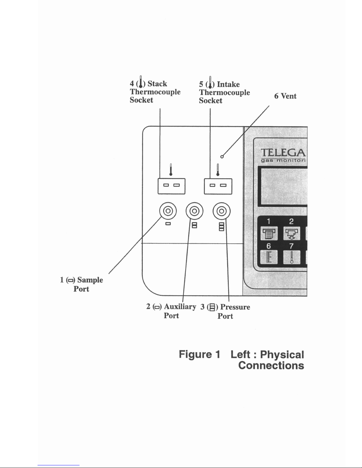
3.1 Left: Physical Connections
This section shows how to connect the sampling probe, thermocouples
and other accessories to the TEMPEST 50 unit. Please refer to Figure 1
for the following reference numbers.
Ref
No
Name
Description/Function
1 Sample Port The port through which the sample gas to be analysed
must pass. The sample line from the probe should be
fitted to the spigot of the sampling port for emissions
measurement.
2 Auxiliary Port Used with a sample conditioning probe, if chosen as an
option.
3 Pressure Port The sample line from the probe should be fitted to the
spigot of the pressure port for pressure/draught
measurement, if chosen as an option.
4 Stack
Thermocouple
Socket
Socket for the thermocouple plug attached to the
sampling probe. When connected the TEMPEST 50
will measure the temperature at the tip of the probe.
5. Intake
Thermocouple
Socket
Socket for a thermocouple plug that may be attached to
an auxiliary thermocouple placed in the intake gas
stream. If this is not fitted a spot measurement of the
temperature of the intake gas may be measured using
the standard sampling probe.
6. Vent Auxiliary vent for use with the sample
conditioning probe.
Page 7
Page 8

3.2 Centre: Control Panel
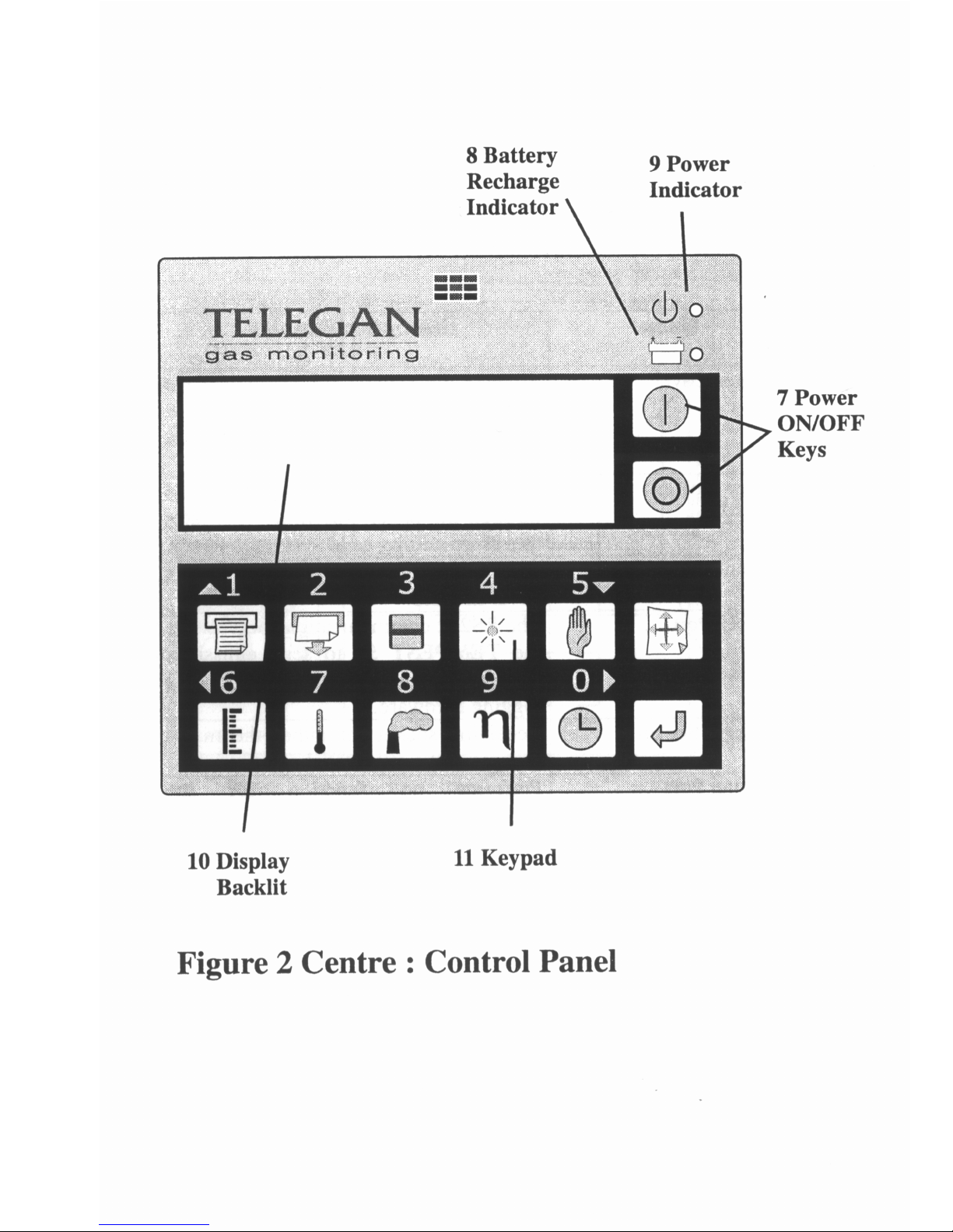
This section details the control panel area which is used to operate the
TEMPEST 50 unit. It incorporates a keypad, display and various
indicators (Refer to Figure 2 Centre : Control Panel).
Ref
No
Name
Description/Function
7 Power On/Off Keys These two keys must be pressed
simultaneously to switch the unit on and off.
This prevents the unit from being turned off
accidentally during operation.
8 Battery Recharge
Indicator
An illuminated green LED next to the battery
symbol indicates that the internal battery is
being charged by an external power source.
9 Power Indicator An illuminated red LED next to the on/off
symbol indicates that the unit is switched on
and receiving power from either the internal
battery or an external power source.
10 Display The area where all the information regarding
the current mode of operation of the
TEMPEST 50 is displayed.
11 Keypad Allows the operator to control the unit and
access the TEMPEST 50 functions using
simple keystrokes. The positions of the
principal keys are shown in Figure 2 and a
tabulated brief description of their functions is
given in Table 1 : Quick Key Reference
(centre page).
Page 9
Page 10

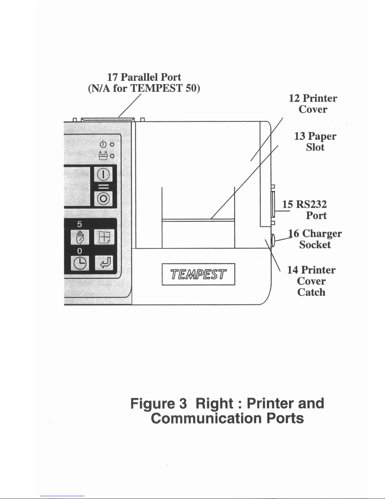
3.3 Right : Printer and Communications
This section describes the physical layout of the integral printer (if
fitted as an option), the charger input socket and the various
communications ports used to send emissions data to external
devices (Refer to Figure 3 Right : Printer and Communications
Ports).
No. Name Description/Function
12 Printer Cover Protects the printer unit from damage
while allowing easy access for
replacement and insertion of the
printer roll and ribbon
13 Paper Slot The printer paper roll should be fed
through the paper slot which also acts
as a sharp cutting edge to tear the
paper.
14 Printer Cover
Catch
Click-tight catch that holds the printer
cover in place.
15 RS232 Port If chosen as an option, the RS232
communications port allows the
TEMPEST to send emissions data to a
suitable terminal or data logging
hardware.
16 Charger Socket Receiving socket for either the mains
charger or the 12V DC charger.
17 Parallel Port Performs no function for the
TEMPEST 50. An additional
communications port for higher
specification units.
Page 11
Page 12
4. QUICK START
This reference section will enable the user to operate the TEMPEST
50 quickly. However, it is advisable to consult the relevant sections
to familiarise yourself with the layout of the TEMPEST 50 (Section
3 - Tempest Grand Tour). For a more detailed explanation of the
set up conditions see Section 5 and for key operations see Section 6.
4.1 Before Starting
Check that the contents supplied (Section 2) are in good condition.
Always use the TEMPEST 50 in the upright position.
4.2 Switching ‘On’
Press the on and off keys together.
4.3 Operation Mode
When switched on the display will read:
- - - - - - - - - - - - - - - -
* * * T E L E G A N * * *
* * T E M P E S T 5 0 * *
- - - - - - - - - - - - - - - -
unless specially configured for you
The display will then countdown a stabilising or calibrating
sequence from 30 to 0 as the unit stabilises before returning to the
initial display as illustrated above.
Listen to check that the pump is running.
Check the current battery charge level by pressing key ‘O’
and reading the percentage battery charge remaining
(Battery (%)):
? If the level is below 40% then it is advisable to change the
battery
? If the level is below 10% then the low battery warning will
be displayed and the battery must be changed.
? The TEMPEST 50 can be used normally with the battery
charger connected.
Page 13
Check that the fuel setting is correct. This is shown below the
Battery (%) status on the display. To select a different fuel press
the menu key once (refer to the Quick Key Reference) then select
option 2 and scroll through the list of standard fuels using the up
and down cursor keys (keys 1 and 5). Select the desired fuel when
displayed (refer to 2 in Section 6.2).
4.4 Probe Position
Select the sampling probe and fit the sample tubing to the sample
port of the TEMPEST 50 unit (1 in Fig 1) and the thermocouple
plug to the stack thermocouple socket (4 in Fig 1). Position the
probe in the flue to take the required sample.
4.5 Taking an Emissions Reading
Press key ‘8’ to obtain the emissions data i.e. the carbon monoxide
concentration plus the nitric oxide and calculated NOx (when fitted
as an option).
Press key ‘9’ to obtain the efficiency data, which includes the
carbon monoxide and oxygen concentrations, the excess air,
calculated carbon dioxide concentration, ratio and efficiency for the
selected fuel.
4.6 Printing (if option available)
To obtain a print-out press key ‘1’.
4.7 Switching ‘Off’
Remove the fitted probe and allow the pump to empty the
TEMPEST 50 of flue gas for about 60 seconds. Switch off by
pressing both ON / OFF buttons together as in 4.2. In transport
ensure that the filter bowl is empty of water (refer to 5.4.3).
Page 14

5. HARDWARE SET-UP
5.1 Power Requirements
The TEMPEST 50 unit can be powered in three ways:
1. Internal rechargeable battery
2. Mains charger and connector
3. 12 V DC charger for use in a vehicle
5.1.1 Battery Operation - the TEMPEST 50 is designed for
battery operation enabling 4-6 hrs continuous use. Fully recharging
the cell takes less than 2 hrs. The approximate percentage battery
charge remaining can be identified by pressing the STATUS key
(Refer to 0 in 6.1) when the unit is switched on. During operation a
low battery warning will indicate when recharging is necessary.
The internal battery will recharge automatically when the unit is
connected to either the mains (Section 5.1.2) or a 12 V DC power
source (Section 5.1.3) and the green power indicator next to the
battery symbol (9 in Fig 2) will illuminate to indicate that the unit is
charging whether the unit is operating or not.
5.1.2 Mains Adapter - the TEMPEST 50 unit can be run
continuously from a mains socket using the standard mains charger
supplied. This adapter should be inserted into the charger socket (16
in Fig 3). To quick-charge (in 2 hours) the unit must be switched on,
otherwise the charging time will be greater than 5 hours.
5.1.3 12 V DC Adapter - the TEMPEST 50 unit can also be run
continuously or charged from a normal car battery via the cigarette
lighter socket using an optional 12 V DC adapter. The power
connector leading from the adapter should be inserted into the
charger socket (16 in Fig 3).
5.2 Sample Probe Attachment
The sample tubing should be connected to the sample port (1 in Fig
1) or pressure port (3 in Fig 1) depending on which measurement is
being performed (emissions or draught measurement, respectively).
The yellow thermocouple plug should be correctly inserted (thinner
pin marked + to the left) into the stack thermocouple socket (4 in
Figure 1) for stack temperature measurement.
Page 15

The user must ensure that the sample tubing is not bent, blocked or kinked
in such a way that the gas cannot be drawn through the unit. When the
sample line is blocked the pump and motor unit will begin to labour
generating increased noise.
5.3 Printer Roll Insertion
The printer cover (12 in Fig 3) can be flicked up by unfastening the printer
cover catch (14 in Fig 3). The paper roll should be placed in the
compartment so that the free end is drawn from below the roll and feeds
towards the front of the unit. A short length of the paper roll (4-8cm)
should be unwound and fed through the printer mechanism by press Key 2
- Paper Feed until the paper is visible. The paper should be fed through
the paper slot (13 in Fig 3) in the printer cover and the cover should then
be shut. Excess paper should be torn off by pulling against the sharp edge
of the paper slot. The printer should now be fully operational.
5.4 Filter Unit
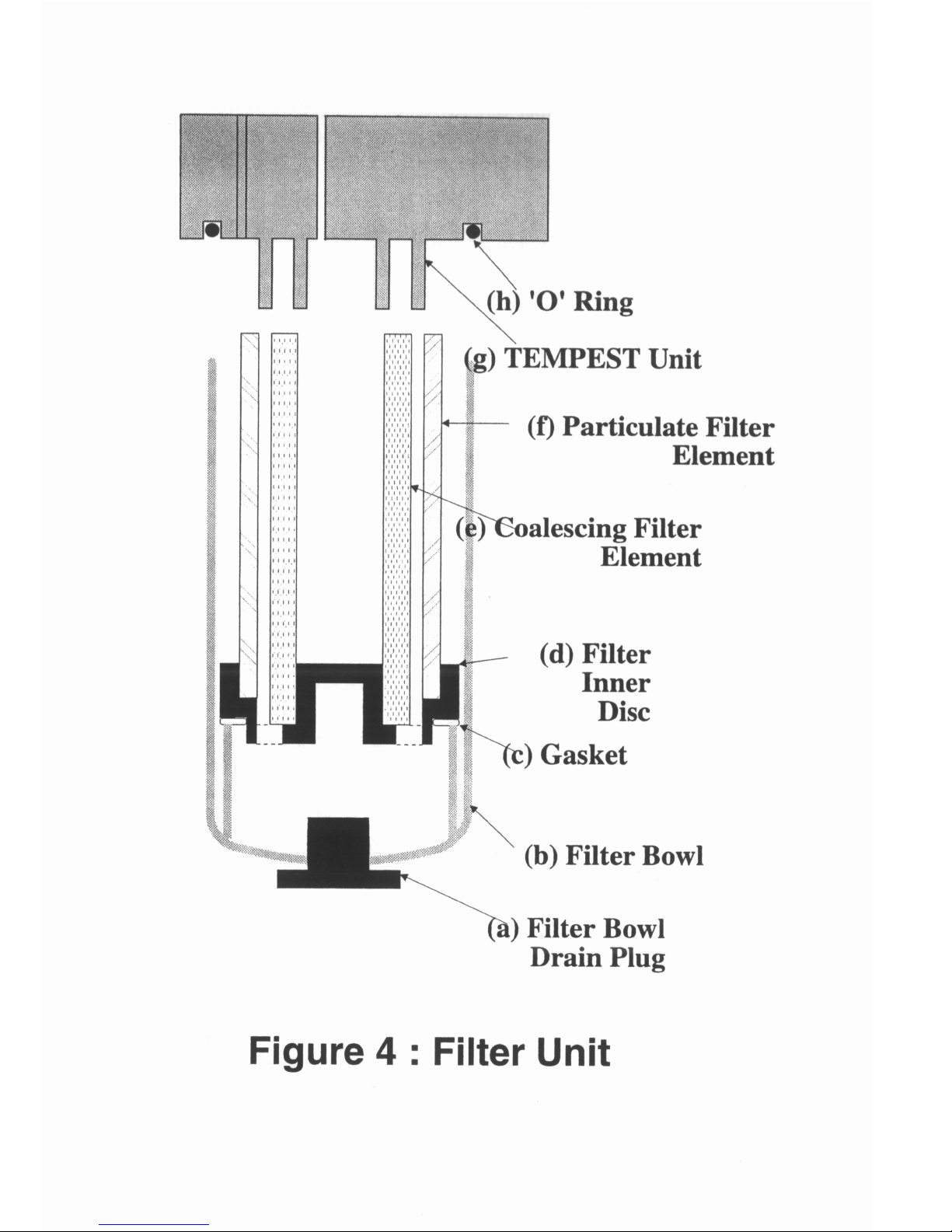
The internal structure of the filter unit (Fig 4) consists of two separate
filter elements (e and f) that are attached at one end to the TEMPEST 50
unit (g) and separated at the bottom by the filter inner disc (d) which
allows water to pass through the assembly to the receiving filter bowl (b).
A gasket (c) is fitted to the filter inner disc to form a seal between the filter
inner disc and the filter bowl.
5.4.1 Assembly - to assemble the filter unit for the initial set up or to
replace damaged filter elements the TEMPEST 50 unit should be turned
upside down after ensuring that the filter bowl has been drained completed
(Section 5.4.3). The filter bowl (b) should be unscrewed clockwise and
removed from the unit. The coalescing and particulate filter elements (e &
f respectively) should be aligned and pushed down onto the TEMPEST 50
unit (g). The gasket (c) should be pushed onto the filter inner disc (d)
which should subsequently be pushed down onto the 2 filter elements (e &
f). Ensuring that the ‘O’ ring (h) is present in the base of the TEMPEST
50 (g) align the filter elements and fittings with the filter bowl (b) and
press against the ‘O’ ring and gasket / filter inner disc. Screw anticlockwise until the bowl locks into place and is held securely.
This action simultaneously exerts a compressive force upon the gasket,
pushing the filter inner disc upwards and producing a tight fit between
the filter elements, the inner disc and the filter bowl.
Page 16
Page 17

Before sampling can commence, ensure that the filter drain plug (a)
is inserted into the base of the filter bowl (b).
5.4.2 Filter Replacement - it is advisable to replace the filter
elements (e & f in Fig 4) when they appear dirty (see re-ordering
information on back page) to prevent filter inefficiency due to
blockage from particulate contamination or water saturation.
Following removal of the filter bowl (as described in 5.4.1) the filter
elements stick due to compression of the filter material and they can
be removed gently by pulling the filter inner disc (d) and gasket (c)
from the filter assembly. The filter elements should be discarded, if
damaged or irretrievably contaminated (see above), or reclaimed by
drying if water saturated. The filter unit should then be reassembled
as described previously (5.4.1).
5.4.3 Water Removal - the water level in the transparent filter bowl
(b) can be observed during operation from the side of the unit and
the filter bowl should be drained of water at any convenient time,
such as before sampling, or before the water level reaches the base of
the filter inner disc (d) and gasket (c). When draining the filter bowl
the sampling pump of the TEMPEST 50 unit should be switched off
(refer to Section 6.3, 6 - Pump (On / Off)) and no emissions data (8
in Section 6.1) should be collected during this short period of time.
The filter bowl drain plug (a) should be removed from the filter bowl
(b) and water allowed to drain away completely. It should be noted
that removing the filter bowl drain plug will allow the ambient
atmosphere to dilute the sample gas stream in the unit and no
emissions data should be collected until this residual air has been
thoroughly flushed through the sampling system. After reactivating
the pump (see 6.3, 6 Pump (On / Off)) allow 60 seconds to
thoroughly flush the sampling system.
5.5 Exhaust Removal
If the instrument is to be used in a confined space, the exhaust gases
that exist the TEMPEST 50 unit following analysis can be vented away
from the user. Attach a suitable connector or flexible tube with the
required minimum internal diameter (15mm) to the exhaust spigot
located on the base of the unit. Care must be taken to ensure that this
vent is not blocked in any way that would prevent the transport of
exhaust gas along the tubing.
Page 18
6. OPERATION
The TEMPEST 50 unit is operated using the membrane keypad located
on the top of the unit (11 in Fig 2) and a brief description of the
specific key functions is given in Table 1 (Quick Key Reference). A
comprehensive guide to the operation of the unit using the Principal
Key Operations (Section 6.1) and menu operations (Sections 6.2 &
6.3) follows:
6.1 Principal Keys
ON / OFF
The TEMPEST 50 unit can be switched on / off by simultaneously
pressing the two keys shown above.
A red light (9 in Figure 2) will indicate that the unit is on and a
characteristic beep will be heard before the start up screen is
displayed:
- - - - - - - - - - - - - - - * * * T E L E G A N * * *
* * T E M P E S T 5 0 * *
- - - - - - - - - - - - - - - -
(Note: This may be configured slightly differently in some cases.)
A green light (8 in Fig 2) will indicate that the unit is connected to a
charger unit. The characteristic noise of the pump will be heard unless
the charger unit is connected, the oxygen concentration is > 20% and
either the flue probe is not connected or the stack temperature is <
50oC=112oF. The unit will immediately begin a stabilising routine and
the following numeric countdown will be displayed, where [X] = 30 to
1:
- - - - - - - - - - - - - - - S T A B I L I S I N G
[ X ]
- - - - - - - - - - - - - - - -
The start up screen is displayed once again (see above) indicating
that the unit is now ready to perform emissions monitoring
functions.
Page 19

1 Print (Optional)
Pressing the print function key will print the emissions data in the
following format (see below).
All temperature (Key 7 - Temperature) emissions (Key 8 Emissions) and efficiency (Key 9 - Efficiency) data will be printed.
If the probe is not attached correctly (Section 5.2) or the stack and
intake thermocouples are not connected then the temperature data
will not be printed.
If the optional pressure or nitric oxide (NO) sensors are not fitted
then the respective data will be absent from the print-out and
display.
- - - - - - - - - - - - - - - * * * T E L E G A N * * *
* * T E M P E S T 5 0 * *
D A T E 0 9 - 1 9 - 0 2
T I M E 1 5 : 1 1 : 0 6
N A T U R A L G A S
A M B I E N T C 2 3
S T A C K C 1 8 7
N E T T C 1 6 2
I N T A K E C 2 5
O 2 % . . . . 1 6 . 3
C O p p m . . . . . 3 5
C O 2 % . . . . . 3 . 5
X A I R % 9 5
R A T I O
E F F % ( N ) 8 5 . 5
P r s . m B a r 9 7 5
N O p p m . . . . . 1 5
N O x p p m . . . . . 1 8
- - - - - - - - - - - - - - - -
Page 20
While printing the following message will be displayed:
- - - - - - - - - - - - - - - -
- - - P R I N T I N G - - O N
- - - - - - - - - - - - - - - -
If at any time the user wishes to stop the printout the hold button
(Key 5 - Hold) should be depressed.
2 Paper Feed (Optional)
Pressing the paper feed function key will advance the paper roll by
one line of print and the following message will be displayed:
- - - - - - - - - - - - - - - P A P E R F E E D
- - - - - - - - - - - - - - - -
3 Data Output (Optional)
Pressing the data output function key will send emissions data
through the RS232 socket so that the data may be accessed using a
suitable terminal. If this key is pressed the following message will
be displayed:
- - - - - - - - - - - - - - - D A T A O U T P U T
- - - - - - - - - - - - - - - -
Page 21
The data will be output in the following manner:
* * * T E L E G A N * * *
* * T E M P E S T 5 0 * *
D A T E 0 9 - 1 9 - 0 2
T I M E 1 5 : 1 1 : 0 6
N A T U R A L G A S
A M B I E N T C 2 3
I N T A K E C 2 5
S T A C K C 1 8 7
N E T T C 1 6 2
C A L . O 2 - - 2 0 . 9 3
X A I R
C O % . . . . . . 0 . 3 5
C O 2 % . . . . . 3 . 5
N O p p m . . . . . 1 5
N O x p p m . . . . . 1 8
E F F % ( N ) 8 5 . 5
P r s . m B a r - 2 8 . 1 5
- - - - - - - - - - - - - - - -
4 Backlight (Optional)
Pressing the backlight function key will turn the backlight on and off.
- - - - - - - - - - - - - - - D I S P L A Y L I G H T
O N
- - - - - - - - - - - - - - - -
The backlight display allows the user to operate TEMPEST 50 in
areas of poor illumination.
5 Hold
When the hold function key is pressed the display will show:
- - - - - - - - - - - - - - - # D I S P L A Y H O L D #
O N
- - - - - - - - - - - - - - - -
before reverting back to the displayed data.
Page 22
When this message is displayed the TEMPEST 50 unit will not
perform any subsequent emissions measurements, update the time
or allow any other parameters to be changed. This enables the user
to hold data or print-out several copies of a set of readings.
Pressing again will turn the ‘DISPLAY HOLD’ off.
6 Scale
When the scale function key is pressed the following measured
parameters will be displayed:
O 2 S T A T U S H I G H
P r s . m B a r . . 9 9 0
O2 STATUS HIGH indicates that the oxygen sensor is producing
sufficient output when placed in air. If the status reads LOW then
the oxygen sensor may require replacement (see back page). The
other line of data is the draught measurement, when the pressure
sensor is fitted as an option.
7 Temperature
When the temperature function key is pressed the following
temperature data will be displayed in the following format using the
selected temperature units, i.e. oC or oF:
I N T A C 1 8
S T A C C 1 9 5
A M B I E N T C 2 3
N E T T C 1 7 7
INTA(KE) The temperature of the air entering the combustion
chamber if an auxiliary probe is fitted.
STAC(K) The temperature measured by the flue gas probe.
AMBIENT The temperature measured by a sensor in the
TEMPEST 50
NETT The difference between the intake (or ambient if no
intake temperature) and the stack temperatures.
Page 23
8 Emissions
When the emissions function key is pressed, any emissions data will
be displayed in the following format:
N O p p m 4 6
N O x p p m 5 2
C O p p m . . 1 0 2
O 2 % . . . . 1 0 . 8
9. Efficiency
When the efficiency function key is pressed the following
parameters (measured and calculated) will be displayed in the
following format:
E F F % 7 3
X A I R O 2 > 2 0 %
O
2 % . . . . 1 0 . 8
C O p p m . . . 5 2
When the efficiency key is pressed again the screen will display the
following parameters (measured and calculated) in the revised
format using the chosen units:
R A T I O . . . 0 . 0 1 2 5
C O 2 % . . . . 0 . 5
O 2 % . . . . 2 0 . 6
C O p p m . . . 5 2
RATIO The ratio of CO (measured) / CO2 (calculated)
CO2 The calculated CO2 concentration obtained from the
measured oxygen concentration O2% and the maximum
theoretical CO2% concentration value (constant) for the
specified fuel.
Page 24
O Status
When the status function key is pressed the following
page of information will be displayed:
D A T E 1 7 - 1 0 - 9 5
T I M E 0 9 : 0 6 : 1 7
B A T T E R Y ( % ) 8 6
N A T U R A L G A S
DATE The date can be displayed in either d-m-y or m-d-y format
(Refer to 0 in Section 6.2 to alter format).
TIME The time is displayed in a 24 hour clock format hours:
minutes:seconds.
BATTERY (%) The battery life remaining.
FUEL The fuel type indicates the currently selected fuel (Refer
to 0 in Section 6.2 to alter fuel selection) used to calculate
parameters such as efficiency, calculated CO2, etc.
6.2 First Menu Page
The menu keys enable a further range of TEMPEST 50 functions
and parameters to be accessed. When prompted for a parameter,
either a number can be input using the numeric keys (0-9) or a
selection can be made by scrolling through a list of options. When
the desired number or option is highlighted it can be selected by
pressing the return key:
MENU
When the menu function key is pressed the following menu
of options will be displayed:
1 - P R I N T 2 - F U E L 3 -
4 - V I E W 5 - 6 - C / F
7 - T E M P 8 - E F F 9 - C A L O 2
0 - D A T E < > - N E X T P A G E
The specific options can be chosen by pressing the appropriate
numeric key (0-9) and each choice will now be described in detail:
Page 25

1-Print
P R I N T T I M E 1 0 : 0 0
O F F
The timed print-out facility enables the TEMPEST 50 unit to
perform discrete sampling and emissions monitoring at predetermined intervals with the emissions data being printed at the
end of each sampling period. Pressing any key (0-9) will toggle the
timed print-out parameter between on and off and the chosen state
can be selected by pressing the return key. If the ‘on’ state is
chosen the following screen message will be displayed:
S E T
P R I N T T I M E 5 : 0 0
The print time can be adjusted using the up and down cursor keys
(Keys 5 and 1) to select the appropriate time interval between
printouts. As soon as the time interval has been selected by
pressing the return key the unit will print the current emissions data
and the following message will be displayed:
P R I N T T I M E 5 : 0 0
- - - - - - P R I N T I N G - - - - - O N
The unit will then automatically print at the selected interval. For
timed print-out periods > 3 minutes the pump will remain inactive
until three minutes prior to the print-out stage. The print-out can be
stopped at any time by pressing the hold key (Key 5). When the
instrument is switched off the timed print-out function status is reset
to the off state.
2-Fuel
S E L E C T F U E L
P R O P A N E
Page 26

The choice of standard fuels can be chosen by scrolling through the
table using the up and down cursor keys:
PROPANE
NATURAL GAS
HEAVY OIL
LIGHT OIL
COKE
COAL
When the desired fuel has been highlighted the return key should be
pressed to choose this parameter.
4-View
S E T
V I E W I N G A N G L E
Following this prompt the viewing angle should be adjusted using
the up (Key 1) and down (Key 5) cursor keys to obtain the optimum
display characteristics i.e. contrast and resolution. If the displayed
characters ‘disappear’ then the viewing angle has been altered to an
extreme angle and should be readjusted until the display can be
clearly read.
Page 27

6-Celsius / Fahrenheit
T E M P E R A T U R E S C A L E ?
C e l s i u s
Pressing any of the numeric (0-9) will toggle the unit of
temperature measurement between degrees Celsius (OC) and
degrees Fahrenheit (oF). When the desired unit is displayed it
should be selected by pressing the return key.
7-Temperature
This function allows the intake temperature to be measured using
the sampling probe and stored in the TEMPEST 50 unit memory
for nett temperature calibration.
S E T I N T A K E T E M P
Y E S
Pressing any of the numeric (0-9) will toggle the intake temperature
setting between the on and off states. When the desired state is
displayed it should be selected by pressing the return key. If the
‘yes’ option is selected then the following message is displayed and
the sampling pump, if not already operating, will be activated:
P L A C E P R O B E B Y
B U R N E R A I R I N T A K E
_ _ _ _ _ _ _ _ _ _ _ _ _ _ _ _
S T A C K C 2 6
At this prompt you should insert the sampling probe into the air
inlet for your burner and allow the displayed temperature reading to
stabilise, at which point the return key should be pressed.
If no intake probe is fitted this reading is now used to calculate the
net temperature and is displayed against the INTAKE heading on
the display.
Page 28

8-Efficiency
E F F I C I E N C Y B A S I S ?
G R O S S
Pressing any of the numeric (0-9) will toggle the efficiency basis
between gross and net efficiency i.e. the calculated efficiencies
based on the gross and net calorific values for the selected fuel
respectively. When the desired state is displayed it should be
selected by pressing the return key.
9-Calibration Oxygen Level
The calibration oxygen level function is used to set the calibration
oxygen level to the ambient atmospheric value (i.e. 20.9% v/v O2).
When this option is chosen the pump will automatically be switched
on, if not already, and a clean air sample should then be drawn
through the instrument. While the oxygen sensor reading is
approaching the calibration value of 20.9% the following screen
will be displayed with the cal.O2 value gradually approaching the
atmospheric value:
D A T E 0 9 _ 1 0 _ 9 5
T I M E 1 5 : 0 3 : 2 8
_ _ _ _ _ _ _ _ _ _ _ _ _ _ _ _
C A L . O 2 - - 2 0 . 9 7
When the oxygen reading has reached a stable value and achieved
its calibration state the bottom line of the display will change to:
O 2 % 2 0 . 9
Page 29

0-Date
D a y - M o n t h - Y e a r
S e l e c t O r d e r
Pressing any of the numeric (0-9) will toggle the date format between
Day-Month-Year and Month-Day-Year.
When the desired state is displayed it should be selected by pressing the
return key. The following screen will be displayed:
D A T E 2 1 - 0 8 - 9 5
S E T
The cursor (underline) indicates which number is selected and either a
different number can be input using the numeric keys (0 to 9 in Figure 2)
or the displayed value can be selected by pressing the return key. In
each case the cursor will move to the next number on the display, six in
total, and each pair of numbers represents each field of the date format
selected previously.
After the sixth number has been selected the display will switch to the
following time selection screen:
T I M E 1 1 - 0 8 - 3 5
S E T
Similarly the cursor (underline) indicates which number is selected
and either a different number can be input using the numeric keys (0
to 9 in Figure 3) or the displayed value can be selected by pressing
the return key. In each case the cursor will move to the next number
on the display, six in total, and each pair of numbers represents each
field of the time format i.e. hours-minutes-seconds.
Note: The clock in the Tempest does not store leap year data and,
therefore, will need to be reset every 4 years e.g. the clock will need
resetting on the 1st January 2000, 1st January 2004 ets.
Page 30

6.3 Second Menu Page
MENU
When the menu function key is pressed a second time the following menu
of options will be displayed if the optional pressure sensor is fitted:
1 - P R E S S U R E Z E R O
2 - P R E S S U R E m B a r / i n W G
4 - P R E S S U R E H O L D
5 - S E R V I C E 6 - P U M P
Else the following reduced menu of options will be displayed:
1 -
2 -
4 -
5 - S E R V I C E 6 - P U M P
The specific options can be chosen by pressing the appropriate numeric
key (0-6) and each choice will now be described in detail:
1-Pressure ZERO (Optional)
Pressing this key will calibrate the internal pressure sensor to standard
atmospheric pressure.
2-Pressure Units (mBar or in WG) (Optional)
S E T
P r s . m B a r 0 . 0 0
Pressing the up and down cursor keys (Keys 5 and 1)
4-Pressure HOLD (Optional)
Pressing this key will prevent the internal pressure sensor updating the
pressure reading so that the information can be printed or analysed at
leisure.
Page 31

5-Service (See Technical Manual)
This key should not be pressed during normal TEMPEST 50 operation.
If the key is pressed accidentally enter a service code of 000000 to return
to the previous screen. If an incorrect code is entered reply to any
prompts by selecting no using the return key to return to the previous
screen.
6-Pump (On / Off)
Pressing this key will toggle the pump between the on and off states. The
appropriate message will then be displayed as shown below:
P U M P
O N
Page 32

7. SPECIFICATIONS
Enclosure Green, TRIAX, IP 345
Dimensions (mm) 280wx120dx112h mm
(=11”wx4¾”dx4½”h)
Weight (no case) 1.4 kg (= 3lbs)
Ambient operating temperature 0o to +40oC (=32o to +104oF)
Internal Power Cell 6v 850 mAh rechargeable NiCd cell
continuous duty 4-5 hours
Battery recharge to full 2 hours
Charger input voltage 115v or 230v, 50/60 Hz AC
Display Liquid crystal display (backlight optional)
Format 4 line 20 character alphanumeric
Probe (standard) construction Pistol-grip with stainless steel shaft
Insertion length 300mm (= 11¾”)
Hose length 2500mm (=98”)
Maximum probe temperature 800oC (=1472oF)
Integral Printer (optional) Impact dot matrix printer
Format 16 characters/line 60 lines/minute
Ribbon Black print life 7000 lines
Paper width 45mm (= 1¾”)
Page 33

Sensors
Measurement Range Resolution Accuracy
Oxygen (O2) 0-25% 0.1% ±0.2%
Carbon Monoxide
(CO)
0-10000 ppm 1 ppm <100 ppm : ±5 ppm
>100 ppm : ±5%
High (CO) 0-10.00% 0.01% <0.10% : ±0.01%
±5% fsd > 0.10%
Nitric Oxide (NO) 0-1000 ppm 1 ppm <100 ppm : ±5 ppm
>100 ppm : ±5%
Probe Thermocouple 0-800oC
(=32o-1472oF)
1oC ±0.3%, ±1oC
(= ±0.3%, ±2oF)
Ambient
Temperature
0-40oC
(=32o-104oF)
1oC ±1oC
Pressure/Draught ±150 mb 0.01mb ±0.5%
Efficiency/Stack loss 0-99.9% 0.1%
CO2 0-99.9% 0.1%
The CO and NO sensors have replaceable filters which should be changed
regularly if used in harsh environments. The expected life for these
sensors is three years under normal operating conditions and for the
oxygen sensor the expected life is two years.
Page 34
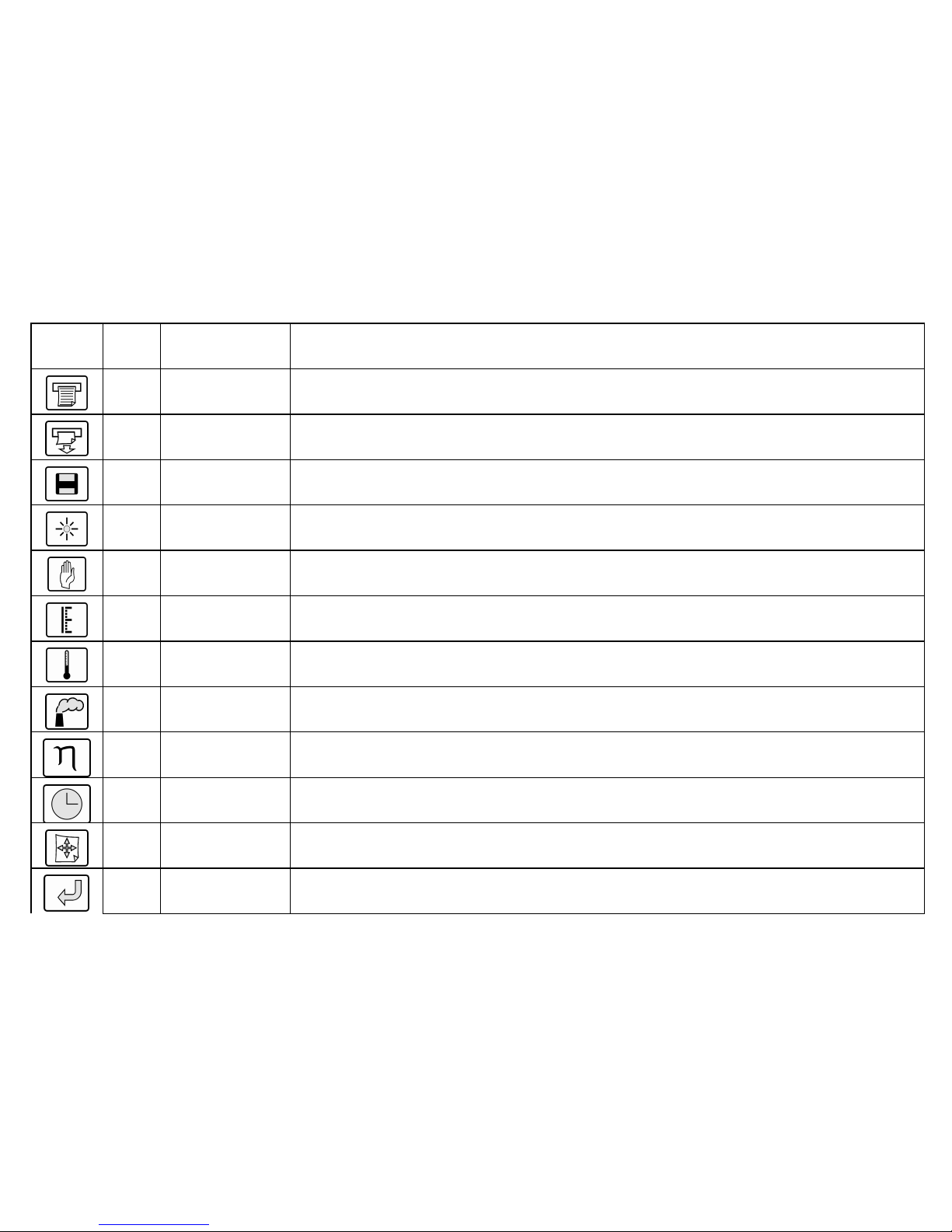
No. Key Description / Function
1 Print
Prints the current emissions data, time and date (when the printer is fitted as an option)
2 Paper Feed
Advances the paper roll by one line (when the printer is fitted as an option)
3 Data Output
Sends emissions data through the RS232 socket so that data may be accessed using a
suitable terminal (when fitted as an option)
4 Backlight
Switches the backlight on and off (when the backlight is fitted as an option)
5 Hold
Freezes the data collection and print functions. If the unit is frozen then asterisks (**)
are printed on both sides of the display. Toggles on / off.
6 Scale
Displays the life remaining of the oxygen sensor and the current pressure reading (when
the pressure sensor is fitted as an option).
7 Temperature
Displays the intake, stack, ambient and net (calculated) temperature values in the
chosen units oC or oF
8 Emissions
Displays combustion gas concentrations
9 Efficiency
Displays the efficiency, excess air, ratio, CO2 (calculated), CO and O2 concentrations
0 Status
Displays the date, time, remaining battery life and current selected fuel
Menu
Displays menu screens to allow user to change settings
Return
Used with the menu key
 Loading...