

Page 1
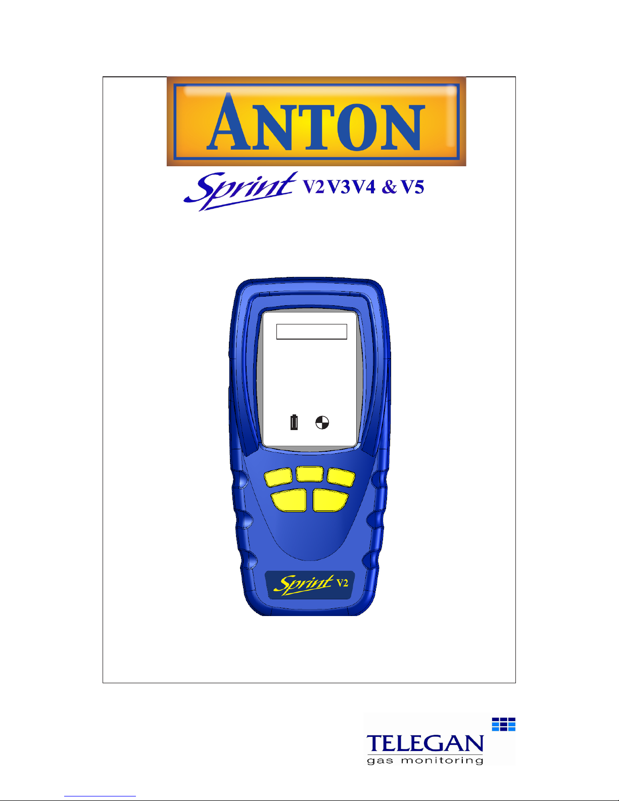
User Manual
INS 29612
November 2011
Issue 6
Multi-function flue gas analyser
Tel: +44 (0) 870 428 0075
Fax: 870 428 0076
www.anton-group.com
+44 (0)
Anton Group
Tel: +44 (0) 870 428 0075
A
NTON
V2.2 i1.05
Page 2
Safety information:
• Read and understand all instructions in the operation
section of this manual before use.
• Do not substitute components as this may impair safety
and invalidate warranty.
• Observe all warnings and instructions marked on the
unit and within this manual.
• If this product is not working properly, read the troubleshooting guide or call Anton.
• Ensure qualified service personnel change sensors and
provide maintenance and calibration.
Additional information:
Sprint is designed to support the working practices defined
in British Standard BS7967 and the Design Standards
EN50379, BS7927 for flue gas analysers. It is highly
recommended that users are fully conversant with BS7967
when using a flue gas analyser for servicing or installing a
boiler system.
Sprint offers a timed let-by/tightness test in accordance
with the UK's Institute of Gas Engineers' procedure IGE/11/
UP/1B.
Performing CO measurements
When performing any CO measurements ensure the unit
is zeroed in clean air in accordance with British Standard
BS7967. A suitable location for sampling clean air will be
outside of the building where the boiler system is installed.
1. Repair of this equipment and gas sensor replacement
shall be carried out by the manufacturer or certified
service centre in accordance with the applicable code
of practice.
2. If the equipment is likely to come into contact with
aggressive substances, then it is the responsibility of the
user to take suitable precautions that prevent it from
being adversely affected.
3. The equipment is designed for use in ambient tempera-
tures in the range -10°C to +50°C and should not be
used outside this range
4. Use only charger(s) supplied by Telegan/Anton.
5. Use only the appropriate Telegan/Anton supplied cables
for connection to the sockets on the instrument.
© Copyright Telegan Gas Monitoring 2011.
All rights are reserved. No part of the document may be photocopied, reproduced, or translated to another language without the
prior written consent of Telegan Gas Monitoring
Publication number: INS 29612
Fifth edition: September 2011
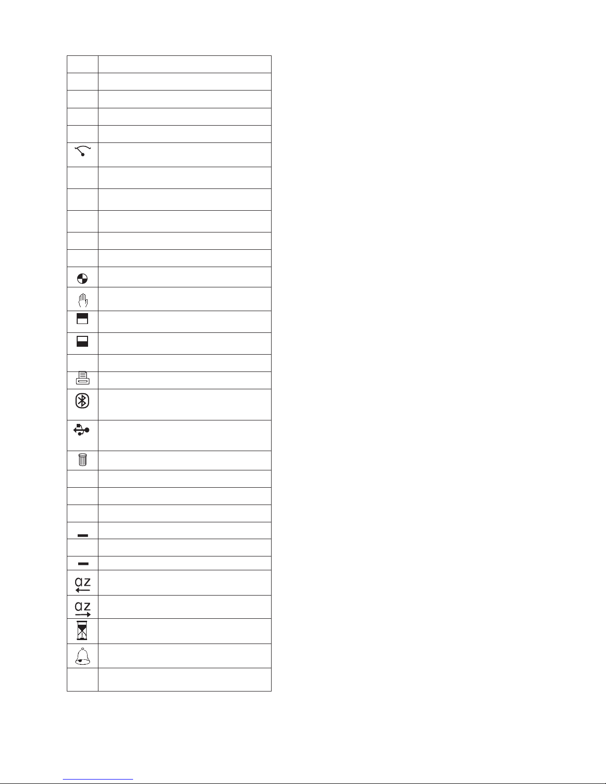
Summary of Screen Icons
þ
Select, pick or action
é
Up item or entry
ê
Down item or entry
ç
Left field
è
Right field
P=0
Zero pressure
u
Start
(Pressure & CO Room Safety tests)
Stop
(Pressure & CO Room Safety tests)
¢
tt
Restart
(Restart timer)
ü
Yes, pass or done
û
No or fail or cancel
Purge icon
Hold / pause readings
T2
T1
Select temp 1 (flow)
(Differential Temperature test)
T2
T1
Select temp 2 (return)
(Differential Temperature test)
<
Save log
Print
Send XML report to Bluetooth
®
(V3+V5 only)
Serial communications with PC in
progress – please wait
Delete
>
Darker contrast
>
Lighter contrast
–
–
Restore default contrast
+
Edit value
+
Increment value
Decrement value
Decrement through character list
(String edit)
Increment through character list
(String edit)
Logging busy
CO Alarm
η
Select Net/Gross/NetHE Efficiency
Bluetooth
®
is a trademark owned by Bluetooth SIG, Inc.
and licensed to Crowcon Detection Instruments Ltd
Page 3

Contents
Sprint V2/V3/V4/V5Multi-function Flue Gas Analyser ............2
Unpacking ..............................................................................................2
Overview ................................................................................................3
Probe connections ..................................................................................4
Quickstart Guide ...................................................................5
I. Operation ........................................................................14
1.1 Menu and operator button overview ..............................................14
II. Setting Up .....................................................................16
2.1 Configuration Options ...................................................................16
III. Battery Charging ............................................................19
Charging the batteries ..........................................................................19
IV. Maintenance and calibration ..........................................20
4.1 Unit ................................................................................................20
4.2 Water trap ......................................................................................20
V. Specification ...................................................................21
VI. Accessories and spare parts ...........................................23
Accessory list ........................................................................................23
VII. Logging ........................................................................24
VIII. Printing and Data Transfer ............................................25
IX. Troubleshooting guide ...................................................26
Appendix I: Carbon Monoxide Room Safety Tests ...............28
Page 4

2
Unpacking Sprint V2/V3/V4/V5
Sprint V2/V3/V4/V5
Multi-function Flue Gas Analyser
Thank you for purchasing the Sprint V2/V3/V4/V5 Multi-function Flue Gas
Analyser. Sprint has redefined flue gas analysis and will give you years of unpar-
alleled service and reliability.
There are four versions covered in this manual as follows:
Sprint V2 Standard full function flue gas analyser
Sprint V3 V2 with
Bluetooth
Sprint V4 V2 with NO sensor included
Sprint V5 V4 with
Bluetooth
Please read the instructions carefully before use. Keep the manual for future
reference.
Unpacking
Important: ensure unit is fully charged.
Remove the Sprint unit from the packaging. The Sprint accessories will be
located in the carry case. Check the contents are complete, you should have:
• Carry case;
• Sprint unit;
• Mains battery charger power supply;
• Rubber boot;
• Flue probe, including water trap;
• A5 user guide;
• User manual on CD;
• Certificate of calibration;
•
2 x 1 m tubes for pressure (Natural gas).
Options to include:
• Gas leak probe;
•
Additional thermocouple probes;
• I
n-car charger;
•
Infra red printer.
Warning:
Do not attempt to use any other charger power supply, with this
unit except the one(s) supplied. Failure to comply could invalidate the warranty and may result in permanent damage to the unit.
Page 5
3
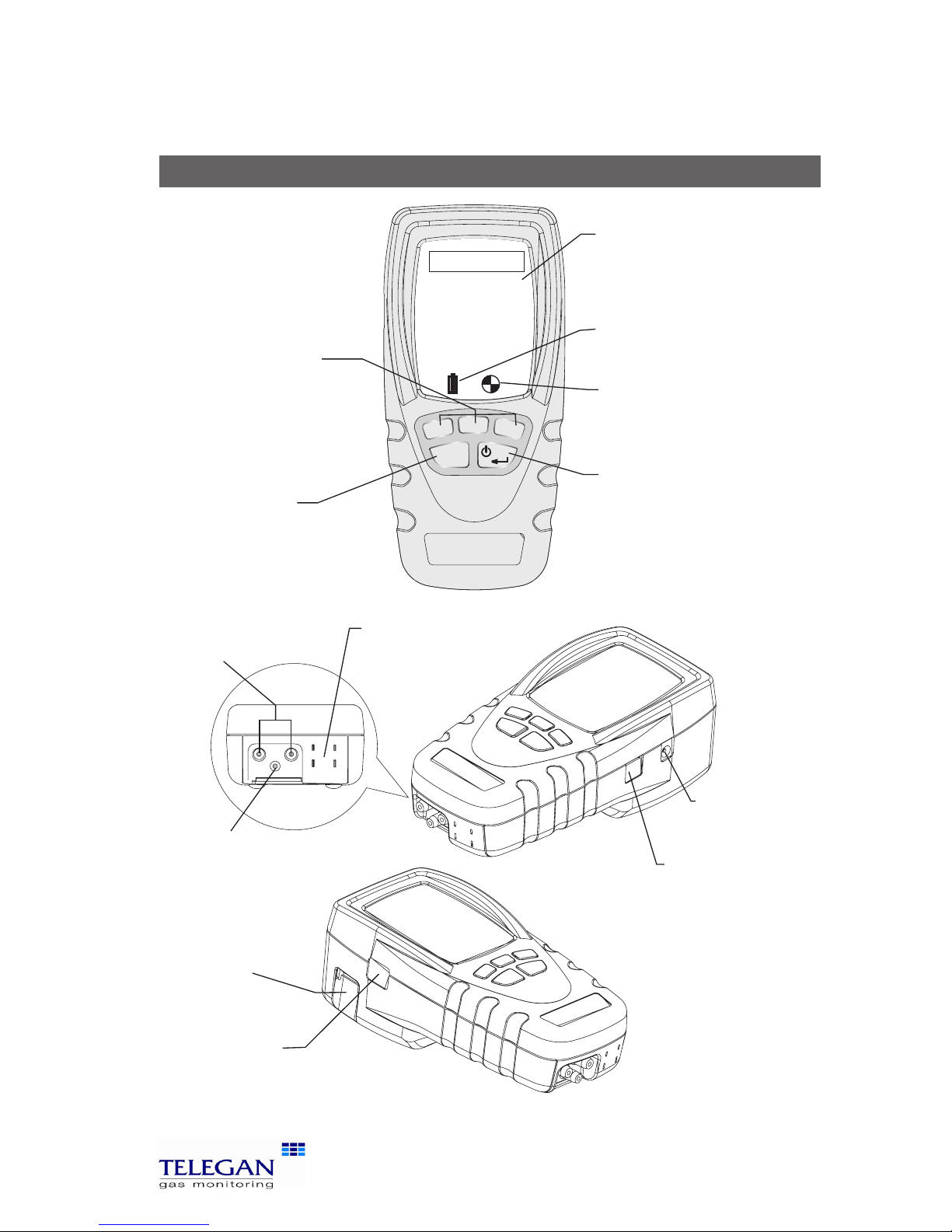
Sprint V2/V3/V4/V5 Overview
Overview
ESC
Tel: +44 (0) 870 428 0075
Fax: 870 428 0076
www.anton-group.com
+44 (0)
Anton Group
Tel: +44 (0) 870 428 0075
A
NTON
V2.2 i1.05
USB connector
Connect gas leak
probe here.
Also used for
communications to PC
Power jack
IR window
Printer output, senses ambient light to
control backlight.
Tip: to quickly activate backlight, cover this window
Note: V3 and V5 have Bluetooth® communications
Exhaust exit
Warning: do not
inhale exit gas exhaust
or block exit
Thermocouple
sockets
K-type connectors
Flue sample inlet
Display
Showing start-up
splash screen
Battery icon
Three bars show
complete charge
ON/OFF/ENTER key
Press and hold button for two
seconds to switch on and switch
off Sprint unit. Use this key to
finish edits, save changes and
view next page of multiple
paged screens.
Soft keys
Use these unmarked buttons
to make selections from the
menu, start and stop tests,
print and store results.
See section Operation for more
details
ESCAPE key
Use this button to quit
tests and step back
through menus.
Pressure inlets
(-) (+)
Purge icon
Rotating icon shows
pump is purging
Page 6
4
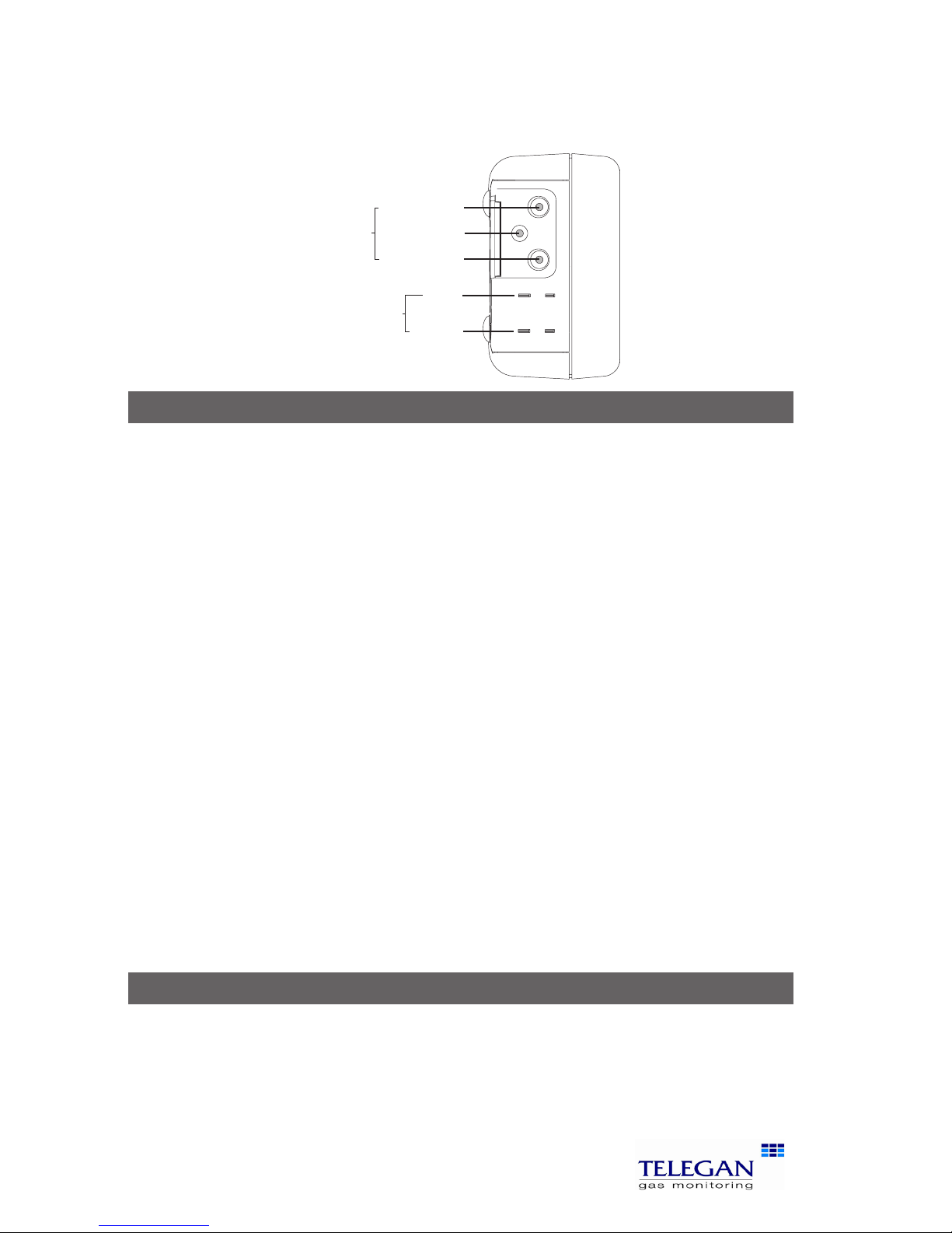
Probe connections Sprint V2/V3/V4/V5
Probe connections
Flue gas analysis
Connect the flue probe to the flue sample inlet and the thermocouple to the
k-connector marked FLOW (Efficiency). To measure flue draught pressure connect pressure tube to (-) Pressure inlet marked draught.
Differential pressure, working pressure, operating pressure and let-by
and tightness test
Connect tubing to pressure inlet(s).
Differential temperature test
Connect one or two thermocouple probes to the k-type connectors. When
using one probe, Sprint will display a soft key option to switch between T1 and
T2 snapshot measuring points.
Room CO safety test
Connect CO room safety test probe (optional), where suitable, to the flue sample inlet.
Gas escape test
Connect gas leak probe to the USB connector.
Note: The pump may operate at different speeds or switch off depending on the test
being performed. This will vary the pitch of the sound from the pump and does not
indicate the pump is performing incorrectly.
Accessories
Sprint is supplied with a rubber boot for protection of your Sprint unit. A magnet on the reverse of the rubber boot can be used to place the Sprint unit in
location on the boiler system for easy hands-free operation. Take care not to
place items which may be sensitive to strong magnetic fields near this magnet,
eg credit cards or magnetic storage devices like computer hard drives.
(-) PRESSURE
(+) PRESSURE
FLUE SAMPLE
INLETS
FLOW
(EFFICIENCY)
TEMPERA
TURE
RETURN
(DRAUGHT)
Tip: see label
underneath unit
for details of probe
connections
Page 7
5
Sprint V2/V3/V4/V5 Quickstart guide
Quickstart Guide
Switch On
Important: please connect flue probe first before switching on your Sprint
unit, ensure the water trap is empty and is fitted in the right direction. Do
not insert probe in flue till after auto zero. Always start in clean air.
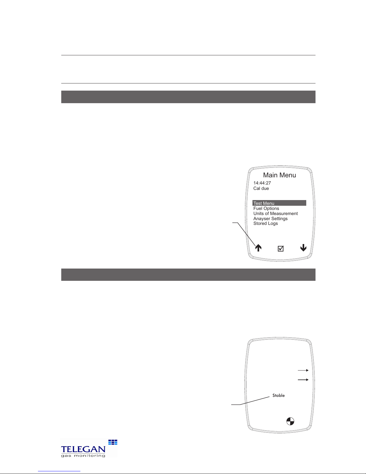
Press and hold the ON/OFF/ENTER key for two seconds. Sprint will emit a few rising beeps, performs a screen test and starts the pump to purge any residual gas
from the unit. Ensure the gas exhaust outlet is not blocked.
The welcoming splash screen is displayed for approximately 30 seconds and will automatically go to the Auto
zero screen. When Auto zero is complete the display will
change to the Test Menu. Warm-up should be extended
if sensor needs to recover from previous gas exposure.
Auto zero
When Sprint has completed warm-up the auto zero screen will be displayed.
Ensure you are in clean air before proceeding.
Tip: auto zero Sprint outside of the building or well away from the heating appliance to
avoid any potential gases in the vicinity affecting the auto zero process.
Ensure the sensor reading is stable, press the proceed ü key to begin auto zero.
After a successful auto zero Sprint will display the Test
Menu screen and switch off the pump.
Note: Sprint will switch off the pump when not performing
tests or purging.
Stable
14:44:27
08-Feb-2006
Purged in clean air
and stable?
CO
Auto zero
NO
Test Menu
Fuel Options
Units of Measurement
Anayser Settings
Stored Logs
14:44:27
Cal due
Main Menu
08-Feb-2006
17-Jan-2007
Tip: see soft key
icon list on the
inside front cover
of this manual
Tip: check sensor reading is
stable. Otherwise Sprint will
display 'Not stable' and arrow
will tilt up or down
Note: image is of V4/V5 Auto
zero screen with NO sensor
Page 8

6
Quickstart guide Sprint V2/V3/V4/V5
Using the menu
From the Test Menu press the ESC key to display the Main Menu. Use the soft
keys to scroll, select and edit menu items (see icon list - inside front cover). Press
accept þ to make change or the ESC key to cancel. Press the ESC key to return
to the Main Menu.
Changing fuel, units and efficiency options
From the Main Menu select Fuel Options or Units of Measurement.
Fuel Options: select one of the following options: natural gas, LPG, heavy oil,
light oil, coal, wood, wood pellet dry, coke, Biomass and Bagasse.
NOx Factor (Sprint V4+V5 only): on selecting the Fuel press accept þ Sprint
will display the Fuel Constants. To edit the NOx Factor use the ê scroll soft
key to select the NOx Factor. Press þ and the NOx Factor screen will be
displayed. Use the soft keys – and + to adjust the NOx factor value, press þ
to accept the change or ESC to cancel.
Units of Measurement: select one of the following options:
Pressure units: mbar, Pa, hPa, kPa, PSI, inWG, mmWG, inHG or mmHG
Temperature scale: Centigrade or Fahrenheit
Efficiency: Net, Gross or NetHE*
*NetHE may be used for High Efficiency/Condensing boilers
NetHE not available on all fuel types
See section II. Setting up for more details.
Changing display and key pad settings
From the Main Menu select Analyser Settings and one of the following options:
Display contrast: use the soft keys to adjust the contrast level.
Auto off timeout: use the soft keys to adjust or disable the timeout period.
Back light: use the soft keys to select one of the following options: off, dim,
bright or controlled.
Key click: use the soft keys to enable or disable audible key click.
Report: Allows selection between 'Printer' and 'Bluetooth' for report output.
Changing date & time, report header and password
From the Main Menu select Analyser Settings>Supervisor settings: (if the
password has been set, enter the password now) select one of the following
options:
Page 9

7
Sprint V2/V3/V4/V5 Quickstart guide
Set date & time: use the soft keys – and + to change units of date and time
and è to select hours, minutes, day, month and year. Press ESC to save.
Edit report header: use the soft keys é and ê to select header text one or two
and + to edit text. Use the and keys to scroll through character lists
and character values. Press è to move on to the next letter in the header
text. Press ON/OFF/ENTER to delete all characters to the right. Press è to
move the cursor to the end of the text and þ to accept change and return
to Edit report header screen. Press ESC to exit edit without saving changes.
Change password: press the soft key + to edit password. Use the and
keys to scroll through character lists and character values. Press è to move
on to the next letter in the password. Press è to move the cursor to the
end of the text and þ to accept change and return to Password screen.
Press ENTER to store the change.
Print Cal Due: Enable or disable printing of calibration due on reports.
Flue CO Alarm: During flue gas analysis, a carbon monoxide alarm can be set
to activate at 300ppm of CO or disabled.
Retrieving stored logs
From the Main Menu select Stored logs and one of the following options:
Select a log: use the soft keys to scroll and select log.
Find a log by number: use the soft keys to scroll up and down the numbered
logs database.
Delete all logs: this option will delete all stored logs. Press accept þ 'Are you
sure?' to clear logs or press ESC to cancel.
Switch off
Turn off unit in clean air and ensure any gas is purged from sensors. Press and
hold the ON/OFF/ENTER button for approximately two seconds. The power off
screen will be displayed and the pump will run to purge the sensors. The pump
will run for up to 30 or 40 seconds to purge unit if gas is present. Sprint will
normally switch off in 10 seconds. Press the ESC key to cancel the switch off
sequence.
Charging battery
Plug the supplied charger into the charger socket. The batteries will recharge
in six hours from flat. You may leave the unit on charge for longer periods, e.g.
overnight, without damaging the unit. A fully charged unit will give up to nine
hours of operation. A shorter charge time can be applied, such as 1/2 hour, to
allow a more limited length of operation.
Page 10
8
Performing tests Sprint V2/V3/V4/V5
Performing tests
From the Main Menu select Test Menu. Refer to section III Operation for more
details.
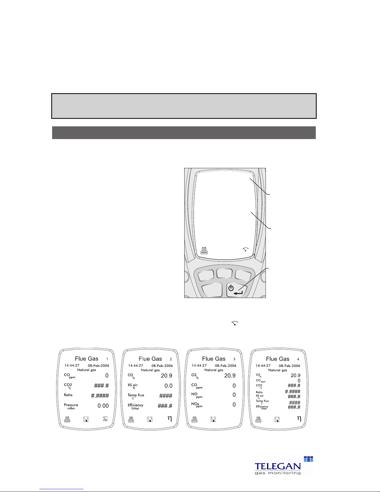
1. Flue gas analysis
Before performing the flue gas analysis test, check the water trap is clean and
is upright (arrow should point in direction of gas flow). To begin test, select Flue
gas analysis from the Test Menu.
Sprint will switch on the pump
and begin making measurements.
Check the fuel type displayed on
the screen is correct. Use the soft
keys to log or print the results.
Press the ON/OFF/ENTER button to
display the three screens available:
Screen 1: CO, CO2, CO/CO2
ratio and pressure.
Screen 2: O2, excess air,
temperature and efficiency.
Extra screen for V4&V5:
O2, CO, NO, NOX
Final screen combines elements from previous screens.
To perform a pressure zero, use the soft key marked
P=0
To end test press the ESC key.
Warning: During testing, ensure the combined filter and water trap is not blocked or
full. Failure to do so may result in an error message.
ESC
14:44:27
08-Feb-2006
Flue Gas
15
Natural gas
CO
ppm
CO2
%
Ratio
mBar
4.8
0.003
0.00
P=0
1
Pressure
Tip: Press the
ON/OFF/ENTER
button to cycle
through the
screens.
Tip: The screen
number is
displayed here.
Tip: If # symbol
is displayed
- flue probe is
not in flue or
not connected.
Screen 1 Screen 2 Screen 3
Screen 4
Page 11
9
Sprint V2/V3/V4/V5 Performing tests
Note: for personal safety a carbon monoxide alarm will activate at 300ppm CO. This
will deactivate when CO levels drop below 150ppm. This is to protect the user from
potential hazardous exhaust gas levels.
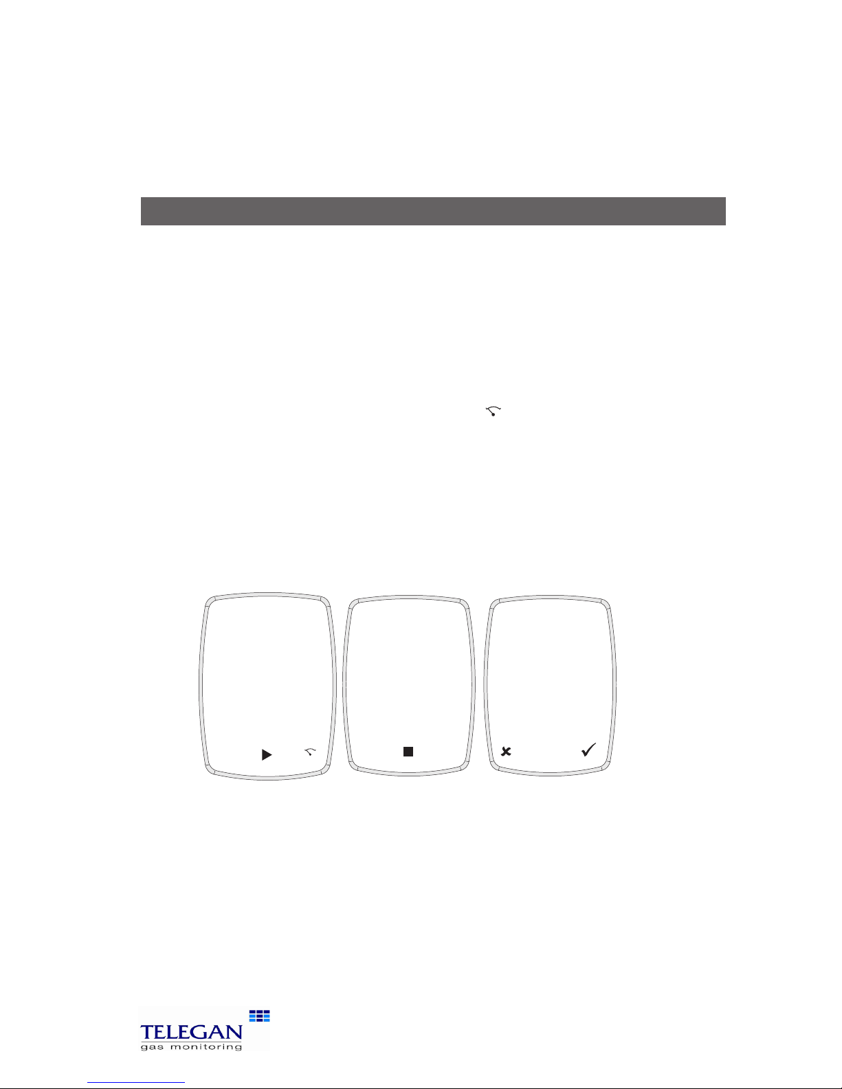
2. Let-by and Tightness test
Let-by test
Before carrying out the test, the pressure must be zeroed with the tube con-
nected to the instrument but not the pressure source. Note: in these tests 'Diff
press' is the difference between start and finish pressures.
1. Select Pressure Menu from the Test Menu. From the Press Menu screen
options select Let-by / Tightness.
2. Connect tube to positive pressure inlet but not pressure source.
3. Zero pressure, use the soft key marked
P=0
.
4. Connect tube to pressure source to begin pressure test.
5. Press the soft key u to start test. Sprint displays the duration time on
the screen.
6. To stop test press the soft key .
7. Press the soft key ü to pass test and proceed to Stabilisation test.
You may fail the test by pressing the key
û
to indicate test has failed
(you can print the results).
Stabilisation Test
1. Press the soft key u to start test. Sprint displays the duration time on
the screen.
2. To stop test press the soft key .
3. Press the soft key ü to proceed to Tightness test.
You may repeat the test by pressing the key
û
(you can print the
results).
14:44:27
08-Feb-2006
Let-by
Finish P2
mBar
Diff press
0.0
P=0
Start P1
mBar
0.0
Duration
00:00
mBar
0.0
14:44:27
08-Feb-2006
Let-by
Finish P2
mBar
Diff press
0.0
Start P1
mBar
0.0
Duration
00:25
mBar
0.0
14:44:27
08-Feb-2006
Let-by
Finish P2
mBar
Diff press
0.0
Start P1
mBar
0.0
Duration
00:54
mBar
0.0
Passed?
Screen 1 Screen 2 Screen 3
Page 12

10
Performing tests Sprint V2/V3/V4/V5
Tightness Test
1. Press the soft key u to start test. Sprint displays the duration time on
the screen.
2. To stop test press the soft key .
3. Press the soft key ü to pass test.
You may fail the test by pressing the key
û
to indicate test has failed.
At the end of the tightness test you can log or print the results. Press the ESC
key to return to Press Menu.
Press ESC again to return to Test Menu.
3. Pressure, Differential Pressure, Working Pressure and
Operating Pressure tests
Before carrying out the test the pressure must be zeroed with the tubes connected to the instrument but not the pressure source. A thermocouple may be
connected to provide temperature readings in these tests.
1. Select Pressure Menu from the Test Menu. From the Press Menu screen
options select Pressure, Diff Pressure. Working pressure or Operating
Pressure.
Screen 1 Screen 2 Screen 3 Screen 4
14:44:27
08-Feb-2006
Stabilisation
Finish P4
mBar
Diff press
0.0
P=0
Start P3
mBar
0.0
Duration
00:00
mBar
0.0
14:44:27
08-Feb-2006
Stabilisation
Finish P4
mBar
Diff press
0.0
Start P3
mBar
0.0
Duration
00:25
mBar
0.0
14:44:27
08-Feb-2006
Stabilisation
Finish P4
mBar
Diff press
0.0
Start P3
mBar
0.0
Duration
00:54
mBar
0.0
Stabilised?
Screen 1 Screen 2 Screen 3
Page 13

11
Sprint V2/V3/V4/V5 Performing tests
2. Connect tube(s) to pressure inlet(s).
3. Zero pressure, use the soft key marked
P=0
.
4. Connect tube(s) to pressure source(s) to
begin pressure test.
5. There is an option to time this test, Sprint
displays the duration time on the screen.
Press the soft key
u
to start test and timer.
6. To stop timed test press the soft key .
7. To restart test press the soft key
tt
.
To re-zero the unit, press
P=0
.
Press the ESC key to return to the Press Menu
screen. To perform the other pressure tests repeat
steps 2 to 7 above.
Press ESC to return to the Test Menu.
4. Differential temperature test
Sprint can perform a differential temperature test with one or two thermocouple probes. To begin test, select Diff Temperature from the Test Menu. Check
the units displayed are the correct temperature scale. If no probes are connected Sprint will display ####.
Two probe test
Connect both probes to the k-type connectors. See label on back of unit for
FLOW and RETURN. Place probes in position. The screen will display the temperature of probe 1 and probe 2, and the differential temperature.
Use the soft keys to log or print the results.
To end test press the ESC key.
Single probe test
When only a single probe is available, Sprint will display
an additional icon on the screen to represent the first and
second reading.
1. Place probe in position to make measurement T1.
2. Press the soft key icon
T2
T1
to take a snapshot
reading of T1. (Do not remove probe until this
snapshot is taken.)
3. Move the probe into position to take second reading
T2. The screen will display the icon
T2
T1
to show
temperature reading T2 is being taken.
14:44:27
08-Feb-2006
Pressure
Pressure
mBar
Duration
0.0
00:00
P=0
Tip:
optional
timer
Tip: plug in the
Thermocouple
probe to view
temperature on
screen.
14:44:27
08-Feb-2006
Ret T2
C
Diff temp
####
Flow T1
C
####
C
####
Temperature
T2
T1
T2
T1
Tip: this icon
will appear when
only one probe is
avaialble.
Page 14

12
Performing tests Sprint V2/V3/V4/V5
The screen will display the snapshot temperature, the live probe
temperature, and the differential temperature.
Use the soft keys to log or print the results.
To end test press the ESC key.
5. Room CO safety test
Ensure the unit has been zeroed in clean air during switch on before
performing this test.
Note: For further details on performing Room CO Safety Tests, see Appendix I.
1. Select CO Room safety from the Test Menu. Sprint will display the
Appliance Menu. Select the appliance from the list.
The appliance will be displayed on the screen during the room CO
safety test.
2. Connect probe if required to the Sprint unit and place at the
recommended height. Refer to British Standard BS7967 if necessary.
3. The pump will switch on in readiness for test. NB. The sound of the
pump operating does not indicate the test has begun. Press the u soft key
to start test. During the test the screen will display the CO reading, peak
CO reading, duration of test and maximum allowed CO for the test.
The test will run for the required duration by appliance according to BS7967.
Sprint will emit an alarm if 30ppm (or 90ppm) threshold is exceeded. Sprint
is programmed with pass/fail criteria for this test. Refer to British Standard
BS7967 for further details on performing room CO safety tests.
When the minimum test period for an appliance has been reached (as defined
by BS 7967:2005 ) the ON/OFF/ENTER key can then be used to cycle through
the CO Room Safety screens. The test can be completed by pressing the soft
key to finish. Use the soft keys to log or print the results.
12:57:24
23-Feb-2009
CO Room
4
Water heater (flueless)
CO
ppm
Peak CO
ppm
Allowed
of test
5
10
07.12
1
Duration
12:57:24
23-Feb-2009
CO Room
Time(Min)
2
12:57:24
23-Feb-2009
CO Room
3
ppm
1
2
5
4
4
of test
07.12
Duration
1
2
3
4
5
Time(Min)
4
4
####
####
####
of test
07.12
Duration
6
7
8
9
10
CO(ppm) CO(ppm)
Page 15

13
Sprint V2/V3/V4/V5 Performing tests
To stop test at any time, press the ESC key. Use the soft keys ü or û to select
'Quit test?'.
When printing Room CO safety test results Sprint will also provide data showing for how long the recommended level of CO was exceeded. This is expressed
as hh:mm > allowed.
6. Gas escape test
Note: Battery power will be used at a higher rate under this test.
Select Gas escape from the Test Menu. Connect the Gas leak probe to the USB
connector, the light will illuminate on the probe. Sprint will display a warning if
the probe is not connected.
Sprint will display 'sensor stabilising' for approximately 30 seconds.
When the sensor is stable the unit will ask 'in clean air?' before zeroing.
Press ü to zero the unit. Sprint will display a bar graph on the screen as gas
levels are monitored.
Place the probe in the area of inspection for several seconds before moving it
to other locations.
Sprint will emit continuous clicks like a Geiger counter. If higher gas levels are
detected the bar graph will increase in readings and the sounder will increase
in pitch.
Press ESC to quit the test.
As with many types of instrumentation the gas leak probe may be damaged
by impact. If the probe is dropped or suffers significant impact in another way
check its operation by first plugging it into the Sprint V and confirming that it
is recognised by the analyser. If this is successful select the gas leak mode and
briefly apply a sample of gas, for example from an unlit cooker ring. This will
allow the user to verify whether the sensor is working correctly or not. If the
gas is not detected contact Telegan or your local distributor to arrange for the
probe to be serviced.
It is recommended good practice that the above check is carried out periodically
even if the user is not aware of the probe being exposed to impact.
Page 16
14
Operation Sprint V2/V3/V4/V5
I. Operation
Before using the Sprint flue gas analyser on any heating appliance installation,
ensure you are familiar with the working practices defined in the BS7967 which
details how to perform certain tests and safety issues to consider.
Auto zero setting
Allow the Sprint unit to auto zero during switch on in clean air before performing any of the following tests: flue gas analysis and room CO safety test.
Ensure all tubes and probes are connected before switch on and zero outside
in clean air.
Pump
Sprint runs the internal pump during purge at switch on and switch off, and
during and after some tests. A rotating purge icon will appear on the screen
when purging. The speed and therefore the sound emitted by the pump, may
vary depending on the test being conducted. To save on the battery life, Sprint
will turn off the pump when it is not required.
When the pump is running ensure the exit gas exhaust is not blocked and do
not breath in the exhaust gases.
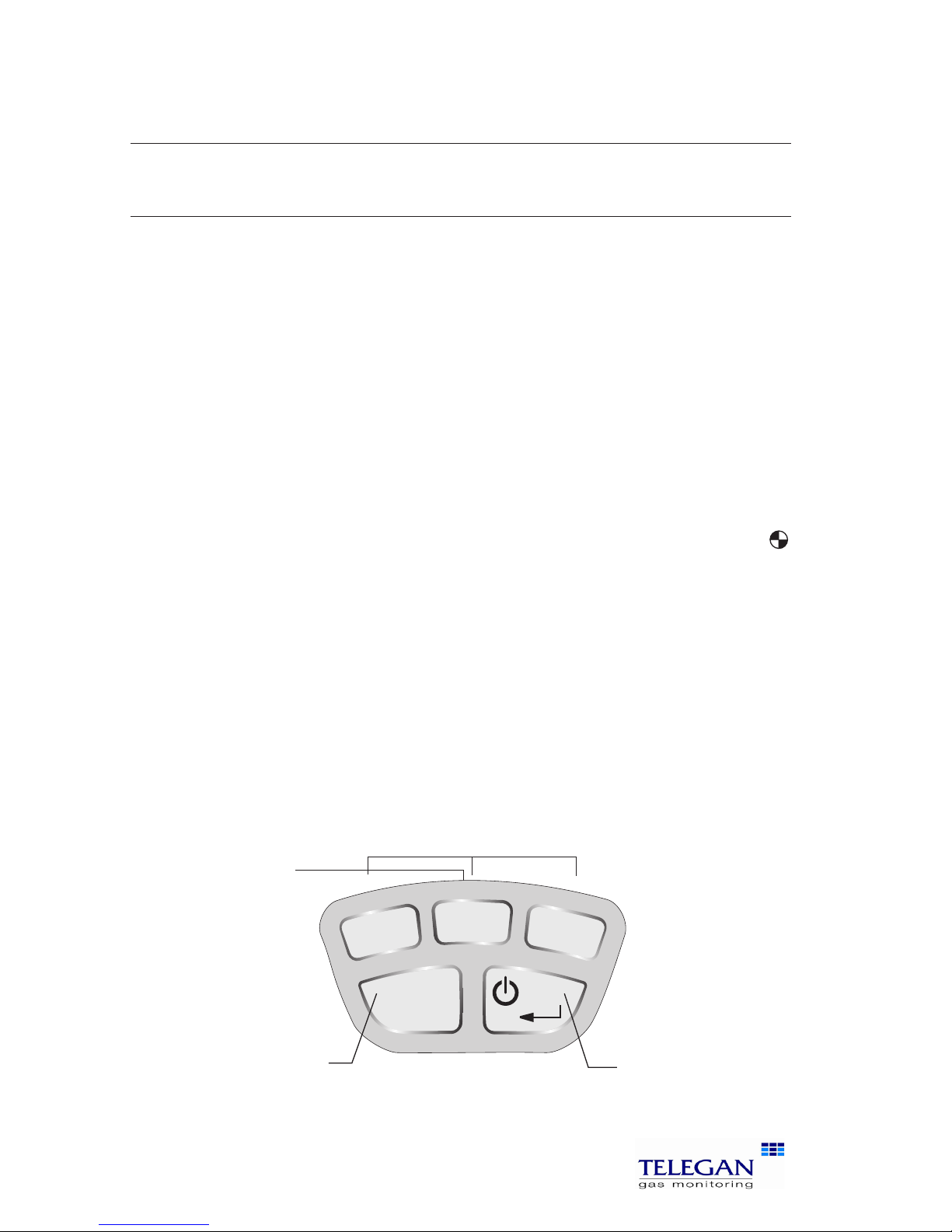
1.1 Menu and operator button overview
Sprint provides a large graphic LCD with blue backlight. Navigation and functions are provided by three soft key buttons which change according to what
you are doing.
ESC
Use the soft keys to
navigate menus,
select, start and end
tests, change options
and select actions.
such as print, log
or zero
Use the escape key
to exit menus, exit
tests and step back
through screens
ON/OFF/ENTER switch.
Use this key to finish
edits, save changes
and view next page of
multiple paged screens.
Page 17

15
Sprint V2/V3/V4/V5 Operation
After your Sprint unit has been switched on and performed an auto zero the
display will show the Test Menu screen ready for use. To display the Main Menu
press the ESC key.
To enter a menu item, use the soft keys below the é and ê screen icons to
scroll the menu list and press the soft key underneath the þ screen icon to
select. Some menus have their own submenu.
Press the ESC key to exit a menu, press ESC twice to return to the Main Menu
from a submenu.
The soft keys control the function displayed above them on the screen. These
will change depending on the test or menu, or if the ESC key is pressed.
The menu structure is shown below:
How to display unit serial number, identity and software
version
Press the ESC key from the Main Menu
Fuels
Test Menu
Main menu
Flue Gas
Analysis
Gas Escape
Detection
CO Room
Safety
Diff
Temperature
Pressure
Menu
Let-by / Tightness
Pressure
Diff Pressure
Appliance
Settings
Display Contrast Back light
Pressure
Units
Temperature
Logs
Select a log Find a log by number Delete all logs
Press ESC to go
to Main menu
Key clickAuto off
timeout
Supervisor
settings
Efficiency
Set date
& time
Edit report
header
Change
password
Reports
(V3+V5 only)
NOx Factor
(V4+V5 only)
Fuel Constant
(V4+V5 only)
Print
Cal Due
Flue CO
alarm
Page 18

16
Setting up Sprint V2/V3/V4/V5
II. Setting Up
2.1 Configuration Options
Fuel Options:
Sprint displays the current fuel option on the screen. To change the fuel option
press the ESC key to enter the Main Menu and select Fuel Options. Use the soft
keys to scroll and select the desired fuel using ü. The new fuel option will be
displayed on the test screens.
Fuel options available are: natural gas, LPG, heavy oil, light oil, coal, wood,
wood pellet dry, coke, Biomass and Bagasse.
Note: NetHE only available for fuels natural gas, LPG, light oil and heavy oil.
From software versions i2.00, fuel types can be changed using Sprint PC Lite.
Units of measurement:
To change the units of pressure, temperature or efficiency press the ESC key to
enter the Main Menu and select Units of Measurement. Use the soft keys to
select the submenu and units for Pressure, Temperature or Efficiency.
Temperature units are: degrees Celsius (ºC) or degrees Fahrenheit (ºF).
Pressure units are: mBar, Pa, hPa, kPa, PSI, inWG, mmWG, inHG and mmHG.
Efficiency units are: Net, Gross or NetHE.
Note: the formulae and constants used for Gross and Net efficiency calculations
are those specified in BS845 (UK-specific) or EN50379 (Europe). In general it
is Net efficiency which is normally quoted. For modern condensing boilers the
Net efficiency calculated may exceed 100%. Sprint V provides a condensing
efficiency calculation via the efficiency option NetHE. The result of this calculation takes into account the recovered latent heat.
Analyser settings:
The Analyser settings menu allows you to alter the settings for the display, auto
off timeout, back light, key pad and Supervisor settings. To change any of these
settings press the ESC key to enter the Main Menu and select Analyser Settings.
Use the soft keys to select the submenus.
Display contrast
On the display contrast screen a bar graph is displayed showing the level of
contrast. Use the soft keys < and > to reduce or increase the level of contrast.
Press the þ key to accept the change or ESC to cancel.
Page 19

17
Sprint V2/V3/V4/V5 Setting up
Auto off timeout
On the auto off timeout screen the number of minutes at which the unit will
automatically switch off is shown. Use the soft keys – and + to reduce or increase
the number of minutes. Press the þ key to accept the change or ESC to cancel.
To disable Auto off timeout press – key until 'disabled' is displayed.
Back light
The back light can be set to four options: off, dim, bright or controlled. Use the
soft keys to scroll and select the option desired. Press the þ key to accept the
change or ESC to cancel.
Back light options are:
Off: switches the backlight off
Dim: lowers the light intensity
Bright: increases the light intensity
Controlled: Sprint monitors the ambient light level and adjusts the light
intensity accordingly.
Reports (V3 + V5 only)
Allows selection of Printer (IR comms) or Bluetooth®. Use the soft keys to toggle
between these and the þ key to accept.
Key click
The Key click settings allows you to enable or disable the key pad from making
audible 'clicks' when pressed. Use the soft keys to select 'enabled' or 'disabled'
from the submenu. Press the þ key to accept the change or ESC to cancel.
NOx Factor (Sprint V4 + V5 only)
The NOx Factor can be viewed and edited from the Fuels Menu. To view the
NOx Factor and other fuel constants, select the Fuel Menu from the Main Menu.
Select the Fuel and press accept þ Sprint will display the Fuel Constants.
To edit the NOx Factor use the ê scroll soft key to select the NOx Factor. Press þ
and the NOx Factor screen will be displayed. Use the soft keys – and + to adjust
the NOx factor value, press þ to accept the change or ESC to cancel.
Supervisor settings
Set date &time
On the Time & Date screen the current time and date are shown. Use the soft
keys – and + to alter the values of hours, minutes, day, month and year. Use the
è key to select each unit. Press the ESC key to accept the change.
Edit report header
Use the soft keys é and ê to select the report header text line one or two.
Press + key to edit text. The screen displays the character lists and highlights
Page 20

18
Setting up Sprint V2/V3/V4/V5
the current list in use. Use the and keys to scroll through character values
in each list and è to move on to the next letter in the header text. The character lists are shown below.
Press ON/OFF/ENTER to delete characters to the right. Press è to move the cursor to the end of the text and þ to accept change and return to Edit report
header screen.
Print Calibration Due
Enable or disable printing of calibration due on reports.
CO Alarm
During flue gas analysis, a carbon monoxide alarm can be set to activate at
300ppm of CO or disabled.
Change password
Press the soft key + to edit password. Use the and keys to edit or create
a password as described above in Edit report header. Press þ to accept change
and return to Password screen. Press ON/OFF/ENTER to store the change.
When a password has been created, Sprint will display the Supervisor password screen on entering Supervisor settings.
! .. / !"# $% & ' ( ) * + , - _ / A .. Z Uppercase alphabet
0 .. 9 0123456789 a .. z Lowercase alphabet
: .. @ : ; < = > ? @ Space
Page 21
19
Sprint V2/V3/V4/V5 Battery charging
III. Battery Charging
The Sprint has a lithium-ion rechargeable battery and will operate for up to
9 hours when fully charged, depending on the type of test used.
Low battery
When the battery is low, Sprint will display a low battery icon. If the battery gets
too low, then Sprint will give further warning before switching off.
Use of the charger as a power adaptor
The Sprint charger can be used to power the unit and will continue to charge
whilst operating the unit.
Automatic battery saver
The Sprint unit will automatically power down if left unused (unless Auto off
disabled). The auto off timeout can be set in Analyser settings. Sprint will warn
user when power down is imminent.
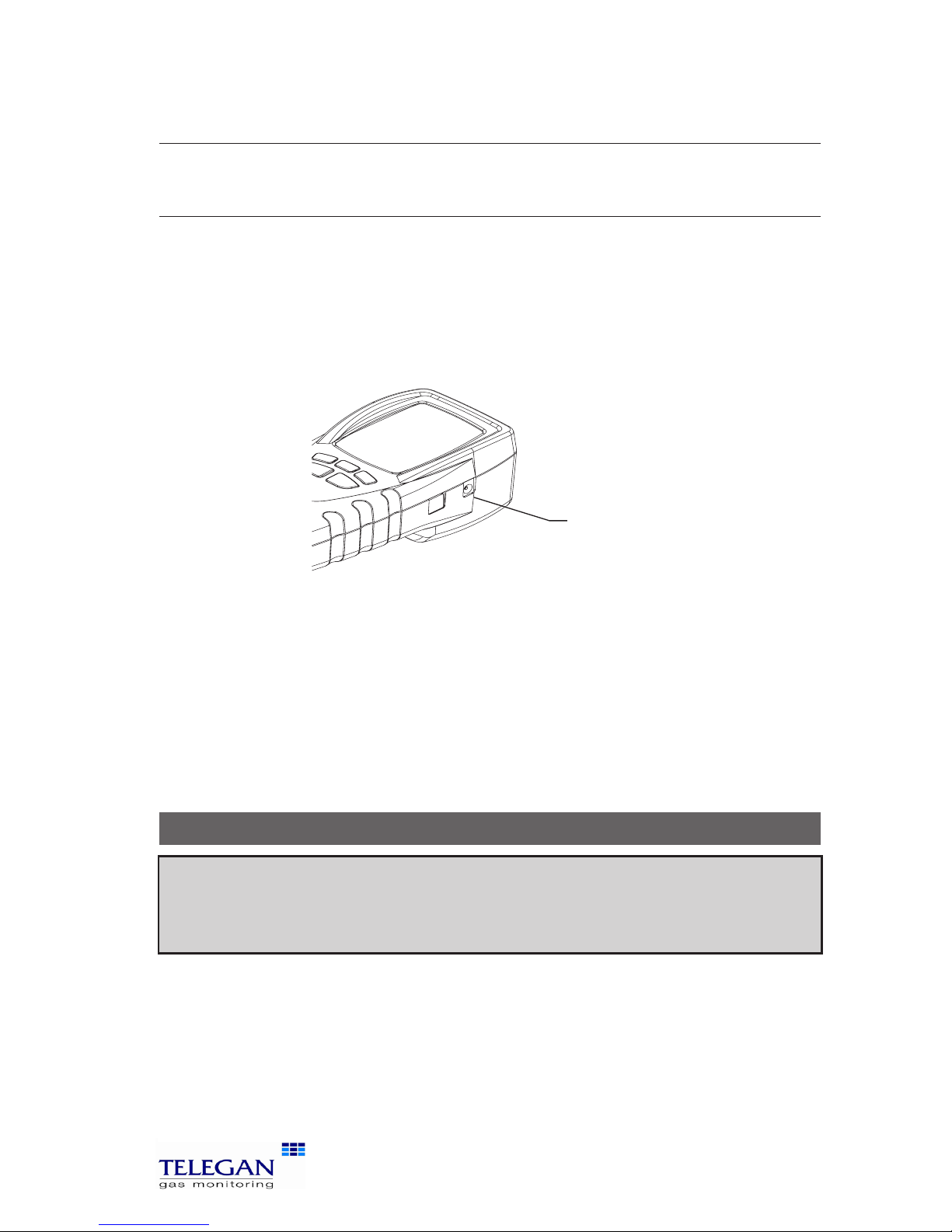
Charging the batteries
1. Plug the charger into a mains socket.
2. Connect the charger to the Sprint using the power jack on the side of
the unit.
Switch on the power at the mains socket. The unit would normally be
left switched off for charging. The display will show the battery charging/
mains connection icon. When the battery is full both icons will flash.
Warning:
Do not attempt to use any other charger with this unit except the one(s) supplied.
Failure to comply could invalidate the warranty and may result in permanent damage
to the unit.
Power jack
Page 22

20
Maintenance and calibration Sprint V2/V3/V4/V5
IV. Maintenance and calibration
General
To keep the display panel and operator buttons free from dirt build-up, regularly
wipe over your Sprint unit with a slightly damp cloth.
Protective boot
To protect Sprint from dirt and knocks a rubber boot is supplied. This boot is
supplied with concealed magnetics in the rear.
4.1 Unit
The Sprint should be calibrated once a year. Your Sprint unit will also display
the calibration due date at switch on and will warn you when calibration due
date is drawing near. If the calibration due date has passed, the Sprint unit will
display a message 'Calibration overdue'.
4.2 Water trap
The combined filter and watertrap is used in-line between the probe and the
unit. Before performing any tests, check that the filter is clean and there is no
water inside the trap.
Filter
The filter element should be changed if the filter has
become contaminated or dirty. If the filter has become
soaked with water, remove from trap and leave to dry
before reusing. Ensure 'O' ring remains in place.
To change the filter
Unscrew the filter-housing, remove the old filter and replace.
Water
To empty the water trap, unscrew the filter-housing, remove the bung and
empty. Replace bung after emptying.
Warning: Filters
must be used at all
times. Failure to do
so may invalidate
the warranty.
Filter
Bung
Residual water
Arrow indicates intended
direction of gas flow
Max water mark. Empty water
before it reaches this mark
Page 23

21
Sprint V2/V3/V4/V5 Specification
V. Specification
Instrument
Operating temperature
range
-10°C to 50°C (14°F to 122°F)
Battery Lithium-Ion. Life up to 9 hours dependant on test
used.
15% left warning.
Recharge time Minimum 6 hours from flat.
Charger input voltage 230 V; 50 Hz AC
Standard Fuels Natural gas, LPG, heavy oil, light oil, coal, wood,
wood pellet dry, coke, Biomass and Bagasse
Display Blue back lit graphic LCD
Menu Intuitive structure, tab selection on screen
Dimensions 75 x 168 x 65 mm
Function buttons/key pad 5 button keypad
Weight 440 g (0.97lbs)
Pump Flow fail indication, SmartPurge
Enclosure Integrated robust protective case.
Protective rubber boot with integral magnets
Standards BS7927, EN50379, BS7967
Data Logging Reports Up to 200 reports, depending on type
Probes
Standard Efficiency Flue Probe
Insertion length 250 mm (9.9”) with adjustable depth gauge
Maximum temperature 800°C (1472°F)
Construction Ergonomic pistol grip with stainless steel shaft, in-
built with thermocouple, in-line water trap/filter
K-type thermocouple Accuracy ±1°C or ±0.3% of reading, whichever
is best
Protective shaft for thermocouple
Hose length 2500 mm (8.2’)
Gas Leak Sensor Probe
Gas Leak Sensor: 0-10,000ppm natural gas
Page 24

22
Specification Sprint V2/V3/V4/V5
Gases
Range Display
Resolution
Accuracy Detection
limit
Response
time
(t90)
Recovery
time
Diagnostics
Oxygen 0-25% 0.1% ± 0.2% 0.3% v/v 50 sec 30 sec
ü
Carbon
monoxide
0-10,000ppm
(H2 compensated,
optional)
1ppm <20ppm;
±3ppm
>20ppm;
±3%
1ppm 90 sec 60 sec
ü
Carbon
dioxide
(Calculated)
0-25% 0.1% ±0.2% v/v 0.2% v/v 50 sec 30 sec
CO/CO2
ratio
0 to 0.9999 0.0001
Nitrogen
Monoxide
(V4 & V5
only)
0-1000ppm 1ppm ±5ppm
or 5% of
reading
5ppm 90 sec 60 sec
Other Measurements
Measurement Range
Temperature
(selectable ºC or ºF)
-50º to 1100ºC (-58º to 2012ºF)
Efficiency 0-100% Net or Gross
0-120% Net High Efficiency
XSAir 0-100%
Draught/Pressure Measurement
Let-by/Tightness Test Dedicated test and report/print structure for
combined test to IGE/11/UP/1B
Pressure Scale
Range -150 mbar to +150 mbar
Resolution 0.1 mbar
Accuracy ±0.5% of reading calibration at +50 mbar
(equivalent to ±0.5 mbar)
Equivalent scales Pa, hPa, kPa, PSI, inWG, mmWG, inHG, mmHG
Communications
IR Port
USB
Page 25

23
Sprint V2/V3/V4/V5 Accessories and spare parts
VI. Accessories and spare parts
Accessory list
Telegan
part number Description
General Spares
CAS29002 SPRINT V CARRY CASE
SFW29001 SPRINT V CD ROM
PRB29002 SPRINT V LEAK PROBE
PRB29000 SPRINT V MAIN PROBE INC WATER TRAP WITH FILTER
TUB29000 SPRINT V Neoprene Tube - 1/4”ID x 3/8” OD (6.35 mm x 9.53 mm)
ENC29001 SPRINT V PROTECTIVE BOOT WITH MAGNETS
CHG29001 SPRINT V UK CHARGER
FIL29001 SPRINT V WATER TRAP INC. FILTER
INS29602 SPRINT V2/V3/V4/V5 INSTRUCTION CARD A5
FIL99008 FILTER ELEMENT
C01296 CHARGING LEAD FOR VEHICLE LIGHTER SOCKET
PRT29005 SPRINTER RECHARGEABLE IR PRINTER
PAP26001 PAPER ROLL FOR SPRINTER
Page 26

24
Logging Sprint V2/V3/V4/V5
VII. Logging
Sprint provides the option to log the results of tests. When a test is complete,
use the soft key < to log the results. The display will show the Create log screen
detailing the log number, log title, date and time. Press the accept key ü to
'Store log?'. The log details recorded are then displayed on the screen. Press the
þ key to continue or the soft keys to print or delete the log.
Recalling logs
To recall a log, use the ESC key to display the Main Menu. Logs can be recalled
either by viewing and selecting from the log list or by entering the log number.
The log list displays the log number, test title and date. Use the soft keys to
choose Select a log or Find a log by number.
When the log has been selected, Sprint will display the log on the screen. The
log data may be displayed on more than one screen. Press the
button to
scroll through screens. Use the soft key options to Print or delete the log. Use
the ESC key to exit the log list and Stored logs menu
.
Printing logs using IR comms
Logs can be printed instantly from the Stored logs or directly after a log has
been recorded and the log is displayed on the screen. Press the Print soft key
to send the log file to the printer.
Deleting logs
Single logs can be deleted either via the Stored logs menu or directly after a
log has been recorded when the log is displayed on the screen. From the Stored
logs Menu choose Select a log or Find a log by number to find the log you wish
to delete. Delete the log using the soft icon.
All logs
can be deleted from the Stored logs Menu. Scroll and select Delete all
logs and press the þ soft key. Press the yes ü key ' Are you sure?' to delete all
logs or press ESC to cancel. Deleting all logs resets next log number to one.
Page 27

25
Sprint V2/V3/V4/V5 Printing and Data Transfer
VIII. Printing and Data Transfer
Printing using IR comms
Ensure your selected printer is switched on with paper roll installed and ready
for use.
Ensure that the IR window on Sprint is aligned with the IR window on the
printer. The printer may be up to 1 m away from the Sprint unit. If a report can
be printed, a printer icon will appear on the screen. Press the soft key under the
icon for an instant print. Ensure printer is set to PC mode.
From software version i2.00
Printing can be aborted by a second press of the print soft key (when the print
icon is reversed) or by pressing ESC to exit the screen.
Data Transfer (V3 + V5 only)
Ensure Bluetooth has been selected from the Report menu. The Print button
will now display the Bluetooth symbol. Data can be transferred to a suitable
Bluetooth enabled PDA with the Sprint PDA application installed or PC running
Sprint PC Lite.
Page 28

26
Troubleshooting guide Sprint V2/V3/V4/V5
IX. Troubleshooting guide
Sprint will provide on-screen messages which advise clear actions. Contact
Anton if unsure on how to proceed.
Symptom Cause Recommended User Action:
Instrument will not
turn on when on/off
button is pressed and
held for 2 seconds.
Battery flat Connect charger and retry.
Battery may be flat. The instrument is designed to prevent
deep discharge occurring and
will turn it self off when battery
level gets too low.
Instrument will not
turn on and charger
symbol is not displayed
when charger is connected.
Battery flattened
beyond standard
charging point.
Ensure charger is correct type.
If so, plug-in and leave connected. Check to see if charging symbol appears every 4-6
hours. If it does not and unit
does not switch on, return
both unit and charger for service.
Pump sometimes operates at a faster rate.
Smart purge is operating. CO sensor is
recovering from exposure to gas.
Remove probe from flue during purge. Continue to use the
instrument as normal.
Pump flow fail alert Filter/water trap or
sample line blocked.
Empty and clean filter/water
trap. Ensure sample line is free
from blockage.
Printer does not
respond or report contains odd characters.
Printer may be off,
faulty, out of range,
incorrectly set-up,
have a low battery or
not facing Sprint.
Ensure printer is charged up
and turned on, working, set-up
correctly with ‘PC’ protocol,
within physical range (usually
1m) and with the IR window
facing the IR window on Sprint.
(Other IR sources such as a PC
or sunlight may give odd character print-out)
Page 29

27
Sprint V2/V3/V4/V5 Troubleshooting guide
Symptom Cause Recommended User Action:
Auto-zero failed Sensors exposed to
gas or faulty.
Switch off and on, ensuring
you zero in clean air and sensors are purged. If unit continues to fail auto-zero, return for
service.
Alarm activates in CO
Room safety test
CO is reading greater
than 30ppm or 90ppm
(cooker).
Dependant on safety procedures.
Cannot remember the
supervisor password.
Forgotten Supervisor password prevents
alteration of report header
which identifies owner of the
instrument. This provides security against theft. So there is no
method to remotely unlock the
instrument. Return for reset
During auto zero the
gas reading does not
stabilise.
Recovering from high
gas exposure or gas
sensor faulty.
Ensure unit is purged and allow
sensor to recover or return for
service ASAP.
Sometimes negative
gas readings are displayed.
Previously zeroed with
gas present.
Turn off and on and repeat
auto zero in clean outside air,
allowing time for the CO sensor to recover and stabilise.
Sometimes “!>” or
“!<” is displayed in
place of a number.
Sensor is out of range. Contact support for advice.
Return for service if problem
persists or other failures are
observed.
Cal due date has
changed.
Time/date has been
amended.
Check current date and time
is correct. If the cal due date is
set to more than a year’s time
then return for service ASAP.
Page 30

28
Appendix I: Carbon Monoxide Room Safety Tests Sprint V2/V3/V4/V5
Appendix I: Carbon Monoxide
Room Safety Tests
Sprint V instruments are designed to assist heating engineers to work to the BS
7967:2005 specification for carbon monoxide room safety testing. You should
refer to BS7967, which defines the requirements, details the methods as well
as the pass and fail criteria for various types of appliances.
CO Room Safety Test in the Sprint V instruments is designed to measure the
build up of carbon monoxide levels in a room where a gas appliance is in use
and record those values each minute for the duration of the test. In addition at
the end of the test it assists the engineer (in an advisory capacity only) to determine whether the test has passed or failed or if the results are invalid. In certain
circumstances, where the results are borderline or open to interpretation, the
instrument will ask the operator to decide if the test has passed or failed, and
will record the operators decision.
Please note: ultimately it is the responsibility of the operator to ensure that the test
is correctly performed to the BS 7967:2005 specification. If the data does not support
the result or the operator suspects it is not reliable due to local conditions (such as
carbon monoxide level changes due to cigarette smoke or vehicle traffic) or incorrect,
then either the test should be repeated or the operator should seek expert advice.
CO Room Test Pass and Fail Test Specifications
Type C:
Room sealed
appliance
Type B:
Boiler
(open flue)
Type A:
Cooker
(flueless)
Type A:
Water heater
(flueless)
Type A:
Space heater
(flueless)
Max Allowed CO: 10 ppm 10 ppm 30 ppm 10 ppm 10 ppm
Max Peak Duration
exceeding Max
Allowed CO:
60 secs 60 secs 20 mins 30 secs 60 secs
CO Alarm Level: 30 ppm 30 ppm 90 ppm 30 ppm 30 ppm
Min Test Duration: 15 mins 15 mins 20 mins 5 mins 30 mins
Max Test Duration: 30 mins 30 mins 30 mins 10 mins 30 mins
Result Codes
The pass or fail result is displayed when the test completes and is printed on
the report as well as recorded in the log. If the test fails a code number is also
displayed, printed on the report and recorded in the log. This fail code identifies the way in which the test failed and can help identify the cause. Also when
Page 31

29
Sprint V2/V3/V4/V5 Appendix I: Carbon Monoxide Room Safety Tests
the test completes a short text message associated to this code is displayed in
a pop-up prompt dialog screen, to explain the reason for failure.
The result codes and associated prompt dialogue messages are as follows:
RESULT & CODE POP-UP PROMPT ON-SCREEN
“PASSED" None
“PASSED (2)" None
ANY “FAILED” “Warning - CO Room Safety test failed.”
“FAILED (1)” CO levels did not fall or unstable.
“FAILED (2)” CO unacceptably high (for too long).
“FAILED (3)” CO dangerously high.
“FAILED (4)” Unacceptable or incomplete.
“Press ESC key to continue.”
Pass Cases
Normal Acceptable Peak of CO
Normally for a test to pass, the CO levels must peak without exceeding the
maximum allowed CO level and then fall (by at least 1 ppm) below the peak
value before the end of the test. Note that it is not necessary for the CO level
to reach or be close to zero at the end of the test, so long as it remains below
the maximum allowed CO level.
The result code is: PASSED
Very Low Levels of CO
If the CO levels remain below 3 ppm (ie: close to clean air or background noise
levels) for the duration of the test, then the test is considered to have passed.
The result code is: PASSED
Failure Cases
Excessive Levels of CO
If the CO level exceeds the CO alarm level then the test is considered to have
failed and should be immediately aborted. The CO alarm may be triggered at
any stage (before, during and after completion of the test) and continues to
annunciate until the CO level returns to a safe level.
The result code is: FAILED (3)
Page 32

30
Appendix I: Carbon Monoxide Room Safety Tests Sprint V2/V3/V4/V5
NB: The alarm should prompt the operator to take appropriate action according to
BS7967 and safety procedures. The sensors in the instrument should be purged with
clean air and allowed to recover.
Unacceptable Levels of CO
A peak duration timer records whenever the CO level exceeds the maximum
allowed CO level during the test. If the total peak duration time exceeds the
max peak duration allowed then the test fails due to unacceptable levels of
CO.
The result code is: FAILED (2)
Operator Pass/Fail Cases
The following results are considered to be operator determined whether the
test passes or fails:
Acceptable Levels of CO with no Peak
For some appliances CO levels may rise to a value beneath the specified limit
and stabilise rather then fall. In this case it is up to the operator to determine
PASS or FAIL.
If operator chooses to fail the test, the result code is: FAILED (4) otherwise the
result code is: PASSED (2)
CO Level Exceeds Max Allowable Level for a Short Duration
For some appliances (eg: cooker) a peak exceeding the maximum allowed CO
level may be acceptable, provided the CO level falls back below this level within
the max peak duration time. It is up to the operator to determine if the result
is acceptable or not.
If the operator chooses to fail the test, the result code is: FAILED (4)
Otherwise the result code is: PASSED (2)
Other Cases
When a test is not performed correctly, the results are inconclusive or there
is insufficient or unreliable data Sprint V attempts to interpret the readings
detected and fail the test. It is possible for the results of a test to appear to be
valid when it was performed incorrectly or the data collected was unreliable in
some way. Please refer to BS7967:2005 and ensure tests are carried out correctly. Sprint V tries to reject incorrectly taken test readings but should not be
relied on to instruct engineers on correct working practice.
Page 33

31
Sprint V2/V3/V4/V5 Appendix I: Carbon Monoxide Room Safety Tests
Multiple Peaks of CO
The overall peak CO reading recorded will be the latest peak CO reading that
was higher than any previous. The peak duration recorded will be the total
time the CO readings exceeded the maximum allowed CO level. The pass /
fail criteria are applied as before based on this information. Sprint V does not
expect to record multiple peaks of CO where the reading goes up and down
more than once.
Unstable or Rising Levels of CO
If there is a significant build up of CO levels at the end of the test and levels are
still rising the test will fail.
The result code is: FAILED (1)
CO Level Exceeds Max Allowable Level and Peaks for Unknown
Duration
If the CO level exceeds the maximum allowed too close to the end of the test
then the test is failed. This can occur if there is a build up of CO levels towards
the end of the test or the appliance fires up late on in the test or the test is
stopped too early. The test should be repeated if this occurs.
The result code is: FAILED (2)
CO Level Does Not Start Close to Zero
It is important that the instrument is zeroed in clean air at switch-on. Failure to
do so will invalidate the test result. BS 7967-2:2005 also requires that the room
is well ventilated prior to starting the test. However it is possible that there may
be a residual background CO level (eg: due to traffic fumes). The instrument
will display a pop-up box prior to starting the test if the CO level is more than
3 ppm.
Page 34

Manufactured by:
Telegan Gas Monitoring
A division of Crowcon Detection
Instruments Ltd
2 Blacklands Way,
Abingdon Business Park
Abingdon
Oxfordshire OX14 1DY
United Kingdom
Tel: +44 (0)1235 557700
Fax: +44 (0)1235 557749
Email: [email protected]
Web site: www.telegangas.co.uk
Exclusive UK Distributor:
Anton Industrial Services Ltd
Unit 6 Greenhill House
26 Greenhill Crescent
Watford Business Park
Watford.
WD18 8JA
United Kingdom
Tel: +44 (0)870 428 0075
Fax: +44 (0)870 428 0076
E-mail:[email protected]
web: www.anton-group.com
Technical helpline: Tel: +44 (0)870 428 0075
 Loading...