

Telegan Anton Sprint V2, Anton Sprint V5, Anton Sprint V3, Anton Sprint V4 User Manual
User Manual
INS 29612
November 2011
Issue 6
Multi-function flue gas analyser
Tel: +44 (0) 870 428 0075
Fax: 870 428 0076
sales@anton-group.com
www.anton-group.com
+44 (0)
Anton Group
Tel: +44 (0) 870 428 0075
A
NTON
V2.2 i1.05
Safety information:
• Read and understand all instructions in the operation
section of this manual before use.
• Do not substitute components as this may impair safety
and invalidate warranty.
• Observe all warnings and instructions marked on the
unit and within this manual.
• If this product is not working properly, read the troubleshooting guide or call Anton.
• Ensure qualified service personnel change sensors and
provide maintenance and calibration.
Additional information:
Sprint is designed to support the working practices defined
in British Standard BS7967 and the Design Standards
EN50379, BS7927 for flue gas analysers. It is highly
recommended that users are fully conversant with BS7967
when using a flue gas analyser for servicing or installing a
boiler system.
Sprint offers a timed let-by/tightness test in accordance
with the UK's Institute of Gas Engineers' procedure IGE/11/
UP/1B.
Performing CO measurements
When performing any CO measurements ensure the unit
is zeroed in clean air in accordance with British Standard
BS7967. A suitable location for sampling clean air will be
outside of the building where the boiler system is installed.
1. Repair of this equipment and gas sensor replacement
shall be carried out by the manufacturer or certified
service centre in accordance with the applicable code
of practice.
2. If the equipment is likely to come into contact with
aggressive substances, then it is the responsibility of the
user to take suitable precautions that prevent it from
being adversely affected.
3. The equipment is designed for use in ambient tempera-
tures in the range -10°C to +50°C and should not be
used outside this range
4. Use only charger(s) supplied by Telegan/Anton.
5. Use only the appropriate Telegan/Anton supplied cables
for connection to the sockets on the instrument.
© Copyright Telegan Gas Monitoring 2011.
All rights are reserved. No part of the document may be photocopied, reproduced, or translated to another language without the
prior written consent of Telegan Gas Monitoring
Publication number: INS 29612
Fifth edition: September 2011
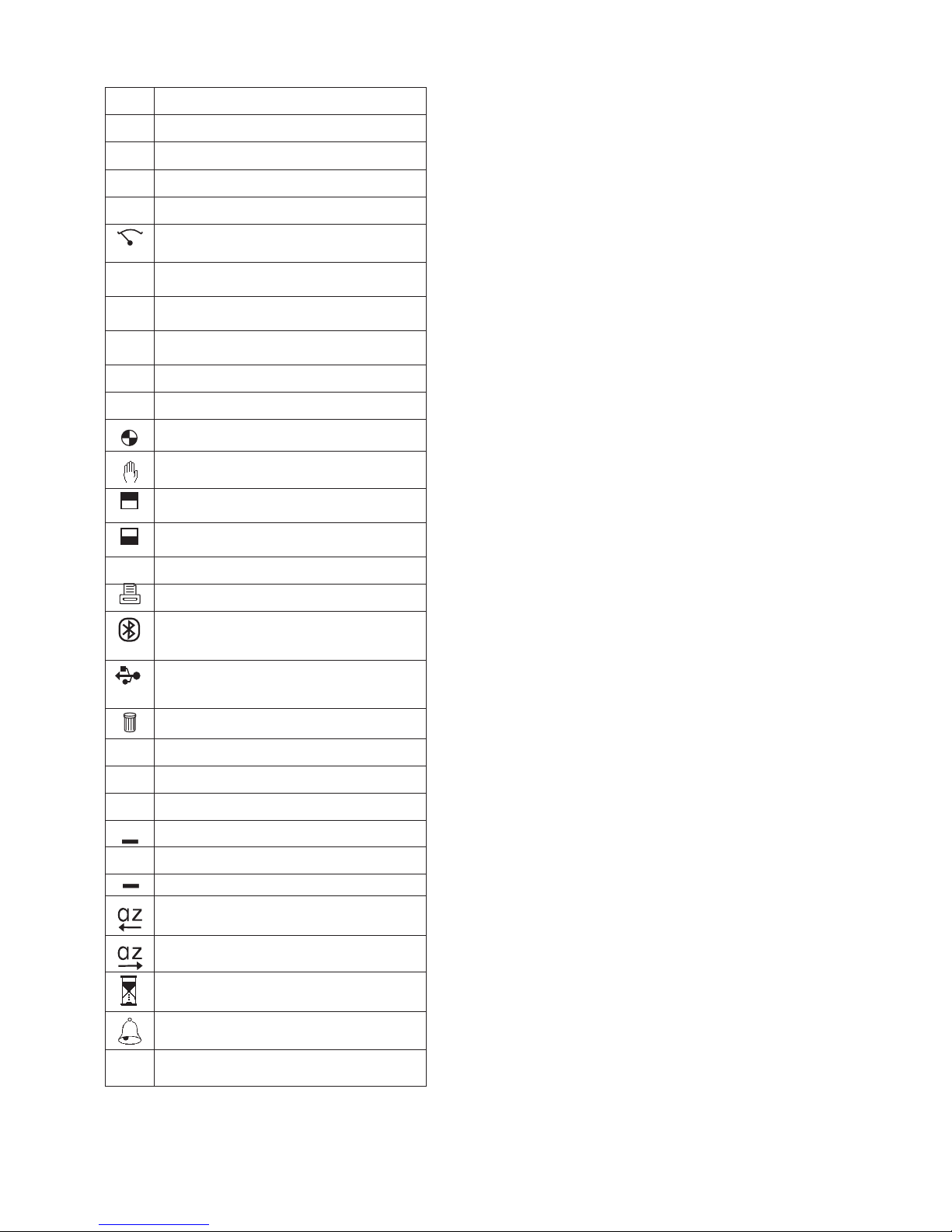
Summary of Screen Icons
þ
Select, pick or action
é
Up item or entry
ê
Down item or entry
ç
Left field
è
Right field
P=0
Zero pressure
u
Start
(Pressure & CO Room Safety tests)
Stop
(Pressure & CO Room Safety tests)
¢
tt
Restart
(Restart timer)
ü
Yes, pass or done
û
No or fail or cancel
Purge icon
Hold / pause readings
T2
T1
Select temp 1 (flow)
(Differential Temperature test)
T2
T1
Select temp 2 (return)
(Differential Temperature test)
<
Save log
Print
Send XML report to Bluetooth
®
(V3+V5 only)
Serial communications with PC in
progress – please wait
Delete
>
Darker contrast
>
Lighter contrast
–
–
Restore default contrast
+
Edit value
+
Increment value
Decrement value
Decrement through character list
(String edit)
Increment through character list
(String edit)
Logging busy
CO Alarm
η
Select Net/Gross/NetHE Efficiency
Bluetooth
®
is a trademark owned by Bluetooth SIG, Inc.
and licensed to Crowcon Detection Instruments Ltd

Contents
Sprint V2/V3/V4/V5Multi-function Flue Gas Analyser ............2
Unpacking ..............................................................................................2
Overview ................................................................................................3
Probe connections ..................................................................................4
Quickstart Guide ...................................................................5
I. Operation ........................................................................14
1.1 Menu and operator button overview ..............................................14
II. Setting Up .....................................................................16
2.1 Configuration Options ...................................................................16
III. Battery Charging ............................................................19
Charging the batteries ..........................................................................19
IV. Maintenance and calibration ..........................................20
4.1 Unit ................................................................................................20
4.2 Water trap ......................................................................................20
V. Specification ...................................................................21
VI. Accessories and spare parts ...........................................23
Accessory list ........................................................................................23
VII. Logging ........................................................................24
VIII. Printing and Data Transfer ............................................25
IX. Troubleshooting guide ...................................................26
Appendix I: Carbon Monoxide Room Safety Tests ...............28

2
Unpacking Sprint V2/V3/V4/V5
Sprint V2/V3/V4/V5
Multi-function Flue Gas Analyser
Thank you for purchasing the Sprint V2/V3/V4/V5 Multi-function Flue Gas
Analyser. Sprint has redefined flue gas analysis and will give you years of unpar-
alleled service and reliability.
There are four versions covered in this manual as follows:
Sprint V2 Standard full function flue gas analyser
Sprint V3 V2 with
Bluetooth
Sprint V4 V2 with NO sensor included
Sprint V5 V4 with
Bluetooth
Please read the instructions carefully before use. Keep the manual for future
reference.
Unpacking
Important: ensure unit is fully charged.
Remove the Sprint unit from the packaging. The Sprint accessories will be
located in the carry case. Check the contents are complete, you should have:
• Carry case;
• Sprint unit;
• Mains battery charger power supply;
• Rubber boot;
• Flue probe, including water trap;
• A5 user guide;
• User manual on CD;
• Certificate of calibration;
•
2 x 1 m tubes for pressure (Natural gas).
Options to include:
• Gas leak probe;
•
Additional thermocouple probes;
• I
n-car charger;
•
Infra red printer.
Warning:
Do not attempt to use any other charger power supply, with this
unit except the one(s) supplied. Failure to comply could invalidate the warranty and may result in permanent damage to the unit.
3
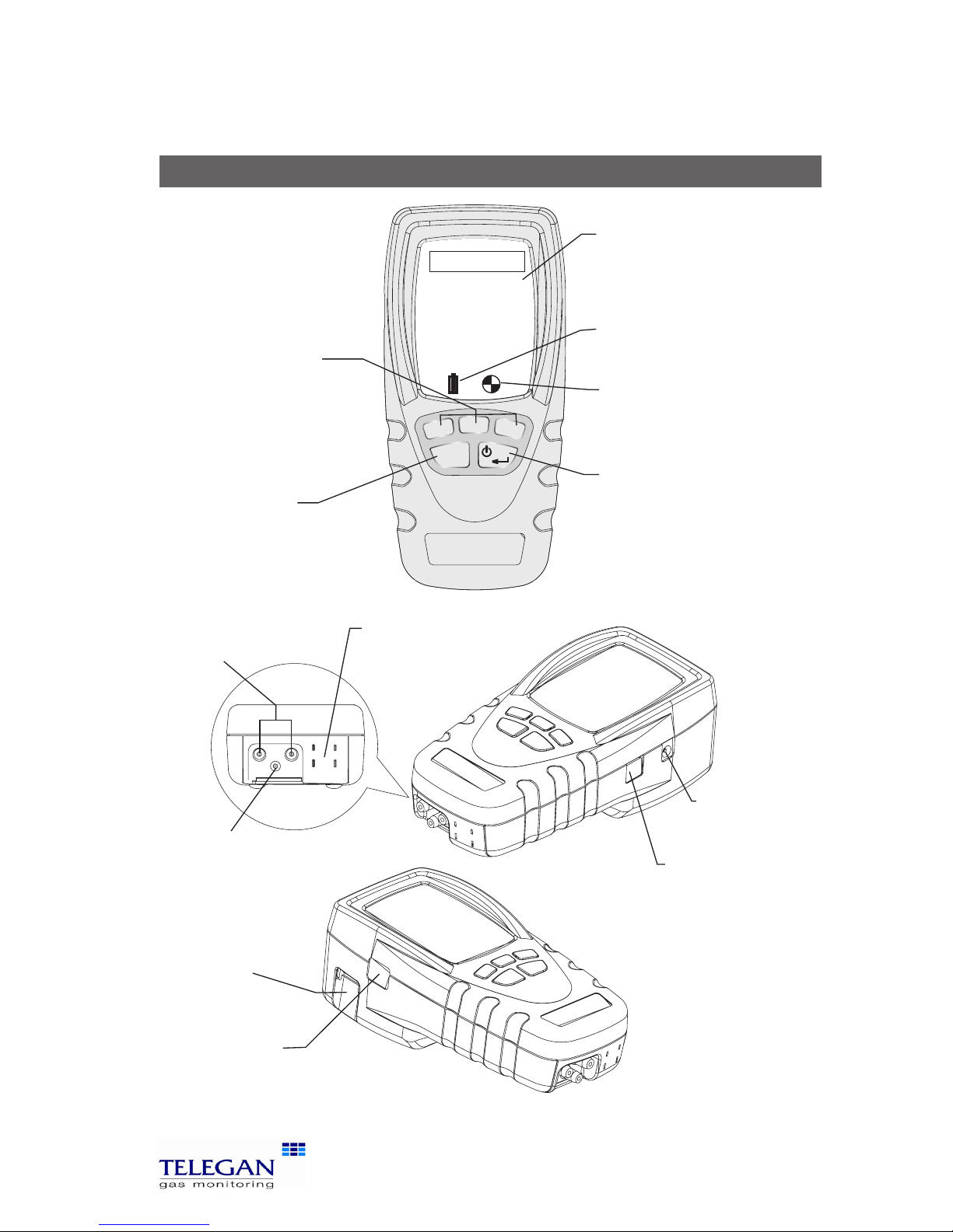
Sprint V2/V3/V4/V5 Overview
Overview
ESC
Tel: +44 (0) 870 428 0075
Fax: 870 428 0076
sales@anton-group.com
www.anton-group.com
+44 (0)
Anton Group
Tel: +44 (0) 870 428 0075
A
NTON
V2.2 i1.05
USB connector
Connect gas leak
probe here.
Also used for
communications to PC
Power jack
IR window
Printer output, senses ambient light to
control backlight.
Tip: to quickly activate backlight, cover this window
Note: V3 and V5 have Bluetooth® communications
Exhaust exit
Warning: do not
inhale exit gas exhaust
or block exit
Thermocouple
sockets
K-type connectors
Flue sample inlet
Display
Showing start-up
splash screen
Battery icon
Three bars show
complete charge
ON/OFF/ENTER key
Press and hold button for two
seconds to switch on and switch
off Sprint unit. Use this key to
finish edits, save changes and
view next page of multiple
paged screens.
Soft keys
Use these unmarked buttons
to make selections from the
menu, start and stop tests,
print and store results.
See section Operation for more
details
ESCAPE key
Use this button to quit
tests and step back
through menus.
Pressure inlets
(-) (+)
Purge icon
Rotating icon shows
pump is purging
4
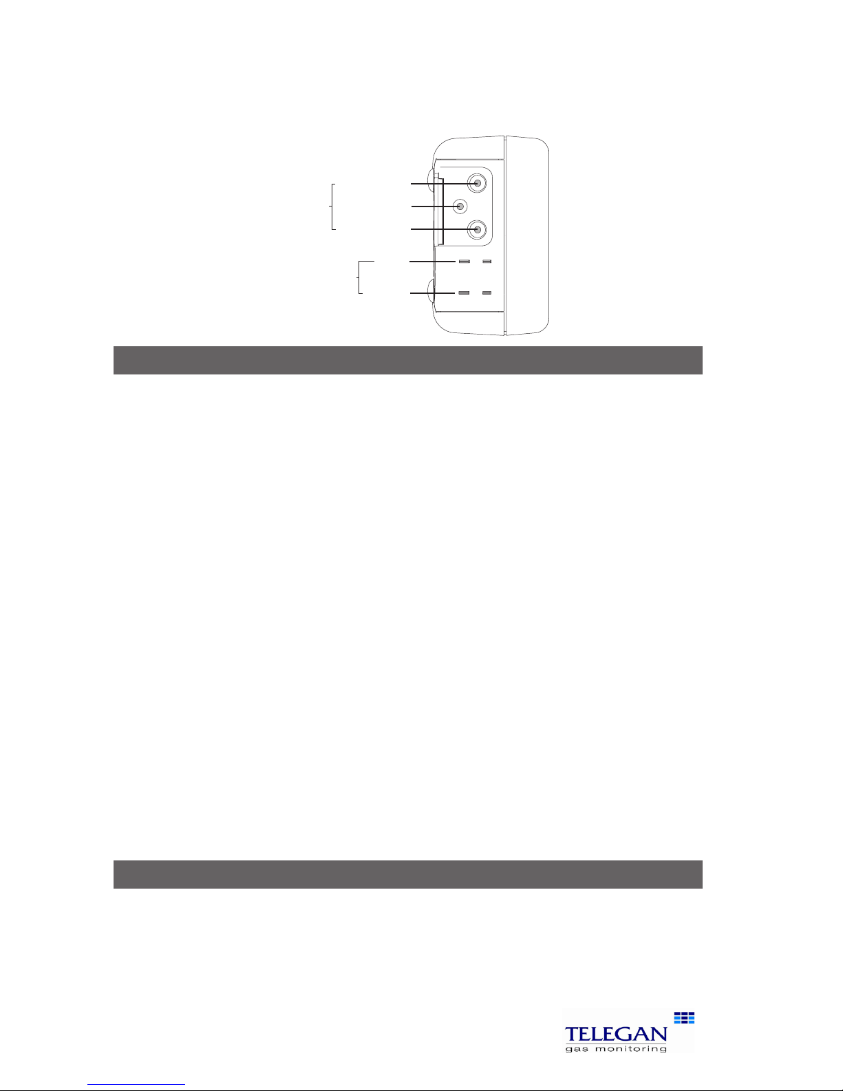
Probe connections Sprint V2/V3/V4/V5
Probe connections
Flue gas analysis
Connect the flue probe to the flue sample inlet and the thermocouple to the
k-connector marked FLOW (Efficiency). To measure flue draught pressure connect pressure tube to (-) Pressure inlet marked draught.
Differential pressure, working pressure, operating pressure and let-by
and tightness test
Connect tubing to pressure inlet(s).
Differential temperature test
Connect one or two thermocouple probes to the k-type connectors. When
using one probe, Sprint will display a soft key option to switch between T1 and
T2 snapshot measuring points.
Room CO safety test
Connect CO room safety test probe (optional), where suitable, to the flue sample inlet.
Gas escape test
Connect gas leak probe to the USB connector.
Note: The pump may operate at different speeds or switch off depending on the test
being performed. This will vary the pitch of the sound from the pump and does not
indicate the pump is performing incorrectly.
Accessories
Sprint is supplied with a rubber boot for protection of your Sprint unit. A magnet on the reverse of the rubber boot can be used to place the Sprint unit in
location on the boiler system for easy hands-free operation. Take care not to
place items which may be sensitive to strong magnetic fields near this magnet,
eg credit cards or magnetic storage devices like computer hard drives.
(-) PRESSURE
(+) PRESSURE
FLUE SAMPLE
INLETS
FLOW
(EFFICIENCY)
TEMPERA
TURE
RETURN
(DRAUGHT)
Tip: see label
underneath unit
for details of probe
connections
5
Sprint V2/V3/V4/V5 Quickstart guide
Quickstart Guide
Switch On
Important: please connect flue probe first before switching on your Sprint
unit, ensure the water trap is empty and is fitted in the right direction. Do
not insert probe in flue till after auto zero. Always start in clean air.
Press and hold the ON/OFF/ENTER key for two seconds. Sprint will emit a few rising beeps, performs a screen test and starts the pump to purge any residual gas
from the unit. Ensure the gas exhaust outlet is not blocked.
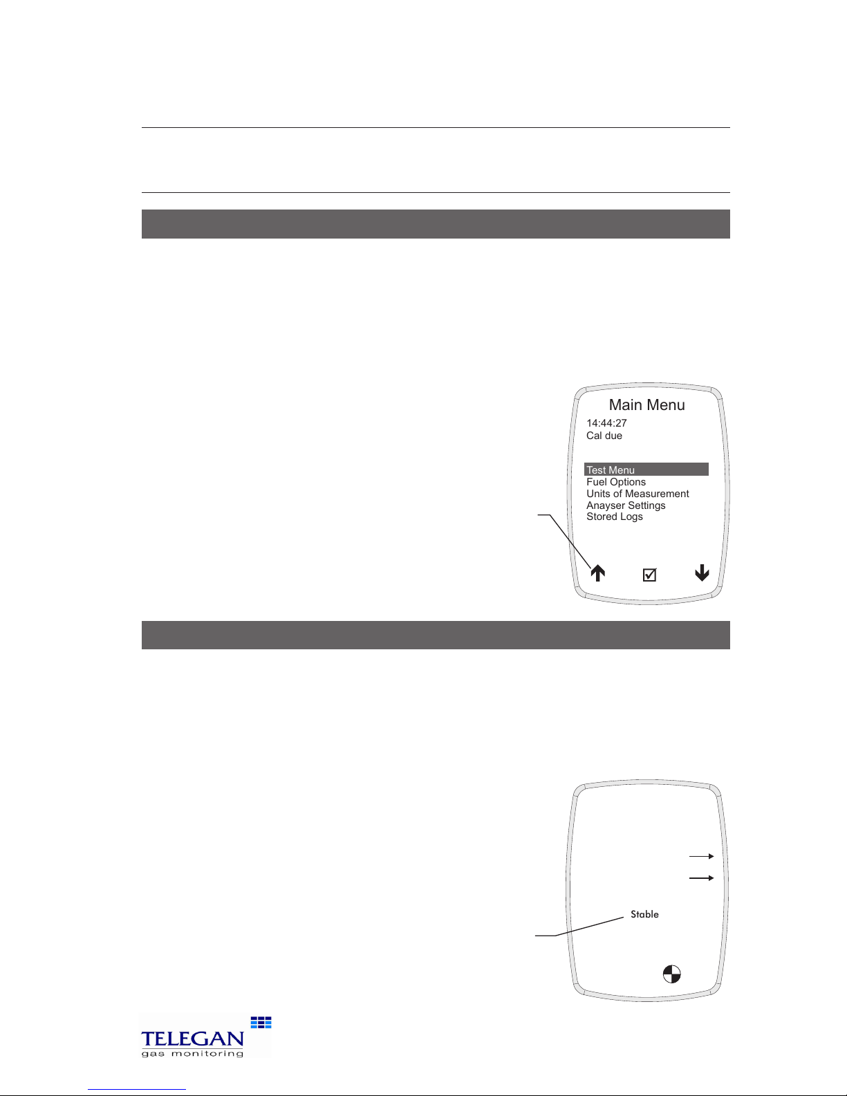
The welcoming splash screen is displayed for approximately 30 seconds and will automatically go to the Auto
zero screen. When Auto zero is complete the display will
change to the Test Menu. Warm-up should be extended
if sensor needs to recover from previous gas exposure.
Auto zero
When Sprint has completed warm-up the auto zero screen will be displayed.
Ensure you are in clean air before proceeding.
Tip: auto zero Sprint outside of the building or well away from the heating appliance to
avoid any potential gases in the vicinity affecting the auto zero process.
Ensure the sensor reading is stable, press the proceed ü key to begin auto zero.
After a successful auto zero Sprint will display the Test
Menu screen and switch off the pump.
Note: Sprint will switch off the pump when not performing
tests or purging.
Stable
14:44:27
08-Feb-2006
Purged in clean air
and stable?
CO
Auto zero
NO
Test Menu
Fuel Options
Units of Measurement
Anayser Settings
Stored Logs
14:44:27
Cal due
Main Menu
08-Feb-2006
17-Jan-2007
Tip: see soft key
icon list on the
inside front cover
of this manual
Tip: check sensor reading is
stable. Otherwise Sprint will
display 'Not stable' and arrow
will tilt up or down
Note: image is of V4/V5 Auto
zero screen with NO sensor

6
Quickstart guide Sprint V2/V3/V4/V5
Using the menu
From the Test Menu press the ESC key to display the Main Menu. Use the soft
keys to scroll, select and edit menu items (see icon list - inside front cover). Press
accept þ to make change or the ESC key to cancel. Press the ESC key to return
to the Main Menu.
Changing fuel, units and efficiency options
From the Main Menu select Fuel Options or Units of Measurement.
Fuel Options: select one of the following options: natural gas, LPG, heavy oil,
light oil, coal, wood, wood pellet dry, coke, Biomass and Bagasse.
NOx Factor (Sprint V4+V5 only): on selecting the Fuel press accept þ Sprint
will display the Fuel Constants. To edit the NOx Factor use the ê scroll soft
key to select the NOx Factor. Press þ and the NOx Factor screen will be
displayed. Use the soft keys – and + to adjust the NOx factor value, press þ
to accept the change or ESC to cancel.
Units of Measurement: select one of the following options:
Pressure units: mbar, Pa, hPa, kPa, PSI, inWG, mmWG, inHG or mmHG
Temperature scale: Centigrade or Fahrenheit
Efficiency: Net, Gross or NetHE*
*NetHE may be used for High Efficiency/Condensing boilers
NetHE not available on all fuel types
See section II. Setting up for more details.
Changing display and key pad settings
From the Main Menu select Analyser Settings and one of the following options:
Display contrast: use the soft keys to adjust the contrast level.
Auto off timeout: use the soft keys to adjust or disable the timeout period.
Back light: use the soft keys to select one of the following options: off, dim,
bright or controlled.
Key click: use the soft keys to enable or disable audible key click.
Report: Allows selection between 'Printer' and 'Bluetooth' for report output.
Changing date & time, report header and password
From the Main Menu select Analyser Settings>Supervisor settings: (if the
password has been set, enter the password now) select one of the following
options:

7
Sprint V2/V3/V4/V5 Quickstart guide
Set date & time: use the soft keys – and + to change units of date and time
and è to select hours, minutes, day, month and year. Press ESC to save.
Edit report header: use the soft keys é and ê to select header text one or two
and + to edit text. Use the and keys to scroll through character lists
and character values. Press è to move on to the next letter in the header
text. Press ON/OFF/ENTER to delete all characters to the right. Press è to
move the cursor to the end of the text and þ to accept change and return
to Edit report header screen. Press ESC to exit edit without saving changes.
Change password: press the soft key + to edit password. Use the and
keys to scroll through character lists and character values. Press è to move
on to the next letter in the password. Press è to move the cursor to the
end of the text and þ to accept change and return to Password screen.
Press ENTER to store the change.
Print Cal Due: Enable or disable printing of calibration due on reports.
Flue CO Alarm: During flue gas analysis, a carbon monoxide alarm can be set
to activate at 300ppm of CO or disabled.
Retrieving stored logs
From the Main Menu select Stored logs and one of the following options:
Select a log: use the soft keys to scroll and select log.
Find a log by number: use the soft keys to scroll up and down the numbered
logs database.
Delete all logs: this option will delete all stored logs. Press accept þ 'Are you
sure?' to clear logs or press ESC to cancel.
Switch off
Turn off unit in clean air and ensure any gas is purged from sensors. Press and
hold the ON/OFF/ENTER button for approximately two seconds. The power off
screen will be displayed and the pump will run to purge the sensors. The pump
will run for up to 30 or 40 seconds to purge unit if gas is present. Sprint will
normally switch off in 10 seconds. Press the ESC key to cancel the switch off
sequence.
Charging battery
Plug the supplied charger into the charger socket. The batteries will recharge
in six hours from flat. You may leave the unit on charge for longer periods, e.g.
overnight, without damaging the unit. A fully charged unit will give up to nine
hours of operation. A shorter charge time can be applied, such as 1/2 hour, to
allow a more limited length of operation.
8
Performing tests Sprint V2/V3/V4/V5
Performing tests
From the Main Menu select Test Menu. Refer to section III Operation for more
details.
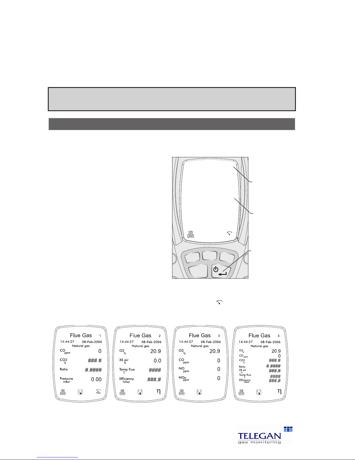
1. Flue gas analysis
Before performing the flue gas analysis test, check the water trap is clean and
is upright (arrow should point in direction of gas flow). To begin test, select Flue
gas analysis from the Test Menu.
Sprint will switch on the pump
and begin making measurements.
Check the fuel type displayed on
the screen is correct. Use the soft
keys to log or print the results.
Press the ON/OFF/ENTER button to
display the three screens available:
Screen 1: CO, CO2, CO/CO2
ratio and pressure.
Screen 2: O2, excess air,
temperature and efficiency.
Extra screen for V4&V5:
O2, CO, NO, NOX
Final screen combines elements from previous screens.
To perform a pressure zero, use the soft key marked
P=0
To end test press the ESC key.
Warning: During testing, ensure the combined filter and water trap is not blocked or
full. Failure to do so may result in an error message.
ESC
14:44:27
08-Feb-2006
Flue Gas
15
Natural gas
CO
ppm
CO2
%
Ratio
mBar
4.8
0.003
0.00
P=0
1
Pressure
Tip: Press the
ON/OFF/ENTER
button to cycle
through the
screens.
Tip: The screen
number is
displayed here.
Tip: If # symbol
is displayed
- flue probe is
not in flue or
not connected.
Screen 1 Screen 2 Screen 3
Screen 4

9
Sprint V2/V3/V4/V5 Performing tests
Note: for personal safety a carbon monoxide alarm will activate at 300ppm CO. This
will deactivate when CO levels drop below 150ppm. This is to protect the user from
potential hazardous exhaust gas levels.
2. Let-by and Tightness test
Let-by test
Before carrying out the test, the pressure must be zeroed with the tube con-
nected to the instrument but not the pressure source. Note: in these tests 'Diff
press' is the difference between start and finish pressures.
1. Select Pressure Menu from the Test Menu. From the Press Menu screen
options select Let-by / Tightness.
2. Connect tube to positive pressure inlet but not pressure source.
3. Zero pressure, use the soft key marked
P=0
.
4. Connect tube to pressure source to begin pressure test.
5. Press the soft key u to start test. Sprint displays the duration time on
the screen.
6. To stop test press the soft key .
7. Press the soft key ü to pass test and proceed to Stabilisation test.
You may fail the test by pressing the key
û
to indicate test has failed
(you can print the results).
Stabilisation Test
1. Press the soft key u to start test. Sprint displays the duration time on
the screen.
2. To stop test press the soft key .
3. Press the soft key ü to proceed to Tightness test.
You may repeat the test by pressing the key
û
(you can print the
results).
14:44:27
08-Feb-2006
Let-by
Finish P2
mBar
Diff press
0.0
P=0
Start P1
mBar
0.0
Duration
00:00
mBar
0.0
14:44:27
08-Feb-2006
Let-by
Finish P2
mBar
Diff press
0.0
Start P1
mBar
0.0
Duration
00:25
mBar
0.0
14:44:27
08-Feb-2006
Let-by
Finish P2
mBar
Diff press
0.0
Start P1
mBar
0.0
Duration
00:54
mBar
0.0
Passed?
Screen 1 Screen 2 Screen 3
 Loading...