

Page 1
TELEFRANG AB
SIOX Climate Controller Module
T05
General Description
T05
is a general microprocessor controller
with
enhanced PLC programmability and
SIOX
field bus communication. It
comprises
two analog outputs and two
inpu
ts. Analog input 1 handles voltage /
current
or thermistor input. Analog input 2
is
preconnected for thermistor input.
Three
digital inputs, two outputs, two
power
relays and one alarm relay are
included.
T05
can work standalone or together with
other
SIOX I/O modules communicating
over
a common wire pair for climate
control,
energy optimisation and alarm
handling.
Versions
:
T05,
SIOX Climate Controller with 2 relay outputs, four cable
glands
and built-in NTC thermistor at AI2 for local temperature
measurement.
T05-1,
SIOX Climate Controller with 3 relay outputs, 3-6 DI, 0-
2 DO, 2-3 AI and 2
AO. A 230 V mains transformer is included.
T05-3, SIOX Heat Exchange Controller with 4
relays, 5 DI, 2 AI
and 2 AO.
T05-4,
SIOX Heat Ex change Controller w ith 4 relays, 5 DI, 2 AI,
2 AO and a Setpoint potentiometer / Mode button.
H:\T05\Man\T05man.wpd/2008-04-07/TF
T05 CLIMATE CONTROLLER MODULE p 2
328/287
General Description
.......................................
1
Versions
.................................................
1
Block Diagram
............................................
3
Power Supply
............................................
3
Installation and Start-Up
...................................
4
Terminal Blocks
..........................................
4
Address Setup
...........................................
5
Analog Outputs
...........................................
6
Analog Output Overrange / Underrange
.......................
6
Analog Inputs
............................................
7
Digital Inputs
.............................................
8
Digital Outputs / Relays
....................................
8
Indicator LEDs
...........................................
9
SIOX Message Transfer for T05
..............................
9
Parameter Setup
.........................................
10
Parameter Specifics
......................................
15
Safety Precautions
.......................................
17
Electrical Specifications
..................................
18
Environmental Specifications
..............................
19
Mechanical Specifications
.................................
19
Assistance
..............................................
19
Page 2
T05 CLIMATE CONTROLLER MODULE p 3
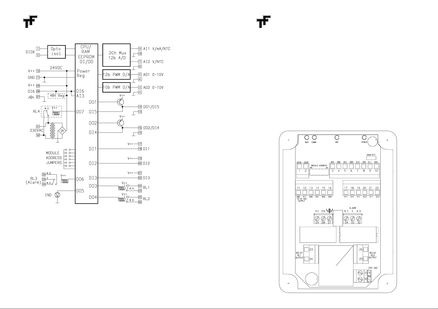
Block Diagram
Power Supply
The
T05 is supplied with 18 V - 35 V DC via the two terminals marked “-/+
24VDC”
on the PC board corresponding to terminals 11/12 in the Block
Diagram
above. The supply GND terminal is connected directly to the I/O GN D
terminals
and the Functional Earthing terminals. Alternatively, a 48 V supply
may
be connected between terminals 28 (+) and 27 (-), which renders DI6 un-
usable.
An external
fuse must be provided on the positive supply with a rating of max
1
A, Quick Blow. The contacts of the two power relays can carry max 10 A at
230 V AC each, and must be externally fused with max 10 A,
Time Lag (Anti Surge), HRC (High Rupture Capacity) fuses.
T05 CLIMATE CONTROLLER MODULE p 4
T05-1
can alternatively be powered from 230 V mains v ia a built-in transformer.
This
connection is shown on next page and must use a separate Pg16 cable
gla
nd and include an external power switch and a fuse of max 10 A. The
current
of the two digital outputs are, howev er, limited to some 10 mA each by
the transformer capacity.
Installation and Start-Up
The
T05 is typically wall mounted using the four corner holes. This mounting
does not affect the IP 65 case sealing. Cables must be entered via cable
glands
that are adequately tightened to prohibit the cords from being pushed
into/pulled
out of the unit. The unit is a Class II equipment intended for
Installation
Category II. Please follow the instructions described under “Safety
Precautions” on page 18.
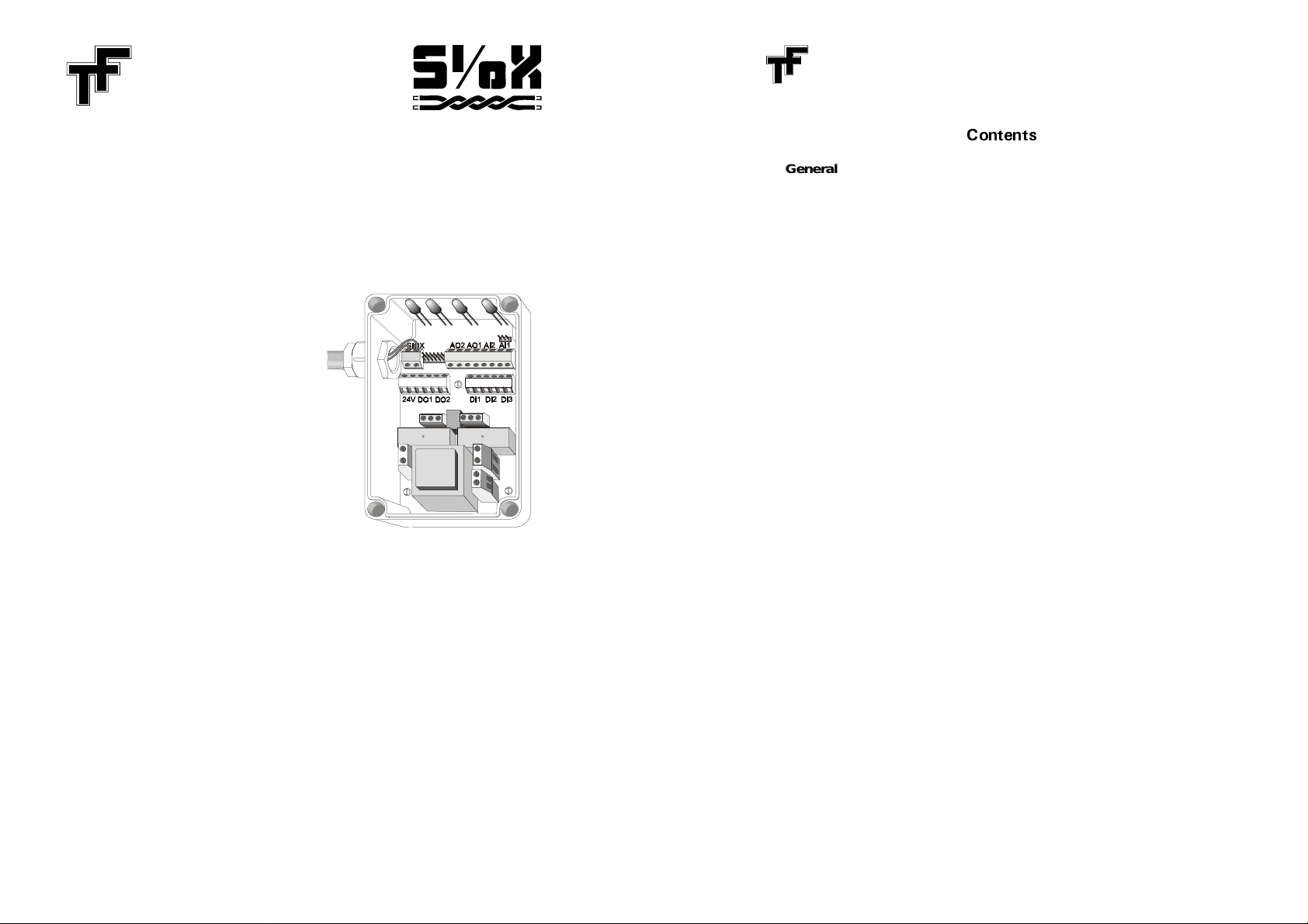
Terminal Blocks
Page 3
T05 CLIMATE CONTROLLER MODULE p 5
Typically, a two-wire, low capacitance twisted pair is used for the SIOX com-
munication
bus. Shielded cables may be used but unless a correct strategy for
shield
grounding is adopted, it may prove to be of little benefit. The total
resistance of the bus must be low, typically below 2 * 50
.
When
a proper supply and the SIOX bus have been connected, the com-
munication
can be tested and operating modes and application PLC program
entered.
Unless otherwise requested, the module is preset at the factory to
communicate
at 4800 bits/s using address 01. General principles for the SIOX
bus
and communications are described in a separate manual, the "SIOX
System
Description". Changes in operation modes are brought about by
Parameter
Setup Strings communicated over the SIOX bus, described on page
10.
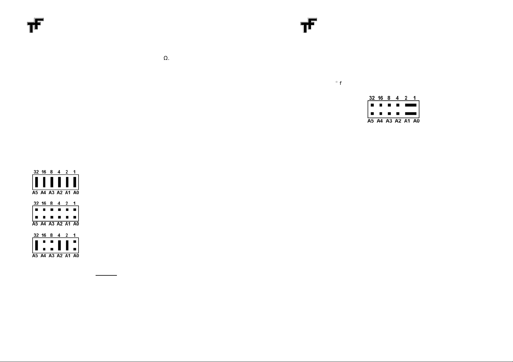
Address Setup
There
are two ways of defining each of the 63 addresses for a T05 module,
either
through jumpers or by the internal EEPROM in the module. If any combi-
nation
of jumpers except all six installed or all six removed is used at power-up,
the module will choose this jumper combination as the correct address.
= 00 : Illegal, will use EEPROM definition.
= 63 : Illegal, will use EEPROM definition.
= 25 : Valid address (16 + 8 + 1 = 25).
The
jumper positions A
0/ - A5 contribute their values 1, 2, 4, 8, 16 and 32 when
the corresponding jumper is
removed
.
All
jumpers installed would generate the invalid address 00, and all jumpers
removed
would be equal to the "reserve" address 63. In this case, the module
checks its internal parameter
0/1 for a valid
address number. Should none be
found, address 63 will be selected.
The
selected address, either from the jumpers or the EEPROM, is finally saved
in
the RAM parameter
0/1
and used for all subsequent communications until this
parameter
is changed or a new power-up is performed. Changing the RAM
address
can be done from the master or from the local PLC program in the
module,
but make absolutely certai n to avoid collision with other modules on
the bus.
T05 CLIMATE CONTROLLER MODULE p 6
A
special feature is added to help recover "lost" modules, i.e. when an unknown
bit
rate and/or address is selected or the PLC runs a program that erroneously
alters
parameters affecting the communication. To recover such a module,
carry out the following steps:
1.
Disconnect power.
2.
Remove
all address jumpers except for A0 and A1 but
rotate
these two
jumpers 90
from their normal position. Please refer to the figure below.
3.
Apply
power. The module will now communicate at 4800 bits/s using
address 63 with the PLC and any options disabled.
4.
Check and reconfigure the module for proper operation.
5.
Restore correct jumper address.
Analog Outputs
The
analog outputs are controlled by values entered in two parameters hex
0/C
and 0/D
and provide pos it i ve voltages between 0 V and 10 V at loads up to 5
mA.
An individual control flag in parameter
0/4/0/
5 changes the range
to 2 - 10
V for either output to suit some types of valves etc.
Analog Output Overrange / Underrange
Normal
12-bit AO control range is hex
0/0/0/0/ - 10/0/0/
= 4097 values within 0 - 10
V
for both AO. AO2, however, being a 10-bit converter will set an output to one
of
1025 values within 0 to 10 V. This means that typically 4 consecutive 12-bit
values,
e.g.
0/0/0/4
- 0/0/0/7, in String Mode or double-byte Data Mode will
generate the same output. (Single-byte Data
Mode permits only 128 different
levels).
Negative
control values, hex 8
0/0/0/ - FFFF (or in Double Data Mode hex 2
/0/0/0 -
3FFF) will set the output to zero (or 2 V if this offset is active).
Positive values hex 1
0/0/0/ - 7FFF will set the output to 10 V.
Page 4

T05 CLIMATE CONTROLLER MODULE p 7
Analog Inputs
The
two inputs are single-ended, meaning that a signal source or transducer
is connected between the input terminal and the adjacent GND.
AI1
can measure a full-scale positive voltage of 0 - 10 V or 0 - 2 V with
reference
to ground with an input impedance of 1 M
and a resolution of 12
bits.
In order to directly measure 0 - 20 mA or 4 -20 mA, an internal 100
load
resistor
is provided. A three-pin jumper area is found close to the AI1 terminals.
By
jumpering the position shown on page 4 as 20mA, the resistor is connected,
and
the 0 - 2 V range can m e asure 0 - 20 mA. The 4 mA offset is handled in
software, see page 12.
The
results of the two measurements are presented in parameters hex 38 and
39,
respectively. Normal output is
0/0/0/0/-0/
FFF,
but it can be modified by the
trimming parameters 7
0/-7B, refer to page 14.
Resistive
transducers such as potentiometers and NTC resistors can be
measur ed by jumpering the two pins marked NTC. This activates a 10 k
resistor
connected to +5 V, supplying current to the transducer. Since the
resulting
analog voltage is non-linear, compensation is handled in software.
This
provides either a linear A/D output value
0/ to hex FFF (12 bits) for a load
resistance variation from 0 to 20 k
,
or a correct temperature value from hex
FE/0C (-50,0) to
/05DC
(+150,0) for a typical NTC resistor of 10 k
at 25
C
with
a resolution of 0,1
C.
AI2
is normally preconnected to measure an external potentiometer or NTC
thermistor
as above, but the m odule may be delivered with this input free for
other
use. Please contact factory for details. The signal type for both inputs
must be defined in EEPROM parameters
/04 / /0
5.
A
third analog input
is available on the terminal marked DI6. Analog input
levels
from 0-24 V to this terminal are converted with 8-bit resolution and
presented
as 12-bit values
0/0/0/0/-0/FF0/ in parameter hex 3A. All scaling and
trimming
must be done in an application program a nd this input is mainly
intended as 24 V supervisor or for simple potentiometer reading.
A
fourth analog input
reads a potentiometer in T05-4. It is limited to 250
value
s shown in parameter hex 3B as
0/0/0/0/ - 0/
FFF.
An extra button is con-
nected
to the pot for special control, readable as DI7 in parameter
0/9.
While
the
button is pressed, the pot cannot be read, and parameter 3B retains the last
reading.
T05 CLIMATE CONTROLLER MODULE p 8
Digital Inputs
Four
digital inputs sensing contact closures are available, marked DI1 - DI3 and
DI6.
They can be manipulated in software to provide a 0-to-1 or 1-to-0 change
only
when their level has been stable for more than a preset time from 1 ms to
1
s. This "debounce" time is preset in EEPROM parameter nr 3, refer to page
17.
Digital input status is available by reading paramet er
0/9.
Two additional
inputs, DI4-5 double as outputs, see below.
The
signals may also be inverted or held in an "edge-trig" register until read by
a
communication. These functions are enabled for individual inputs in par-
ameters
/0A and /0B. Note that repeated communications with the DI parameter
will
not clear such an edge flag until you undertake an access to another
address or parameter.
DI1 also includes a pulse
counter, incrementing on each positive edge of the
input
at 500 Hz max rate. The counter parameter 1
0/ may be read, preset or
cleared at any time. It folds over to 0 after 65536 pulses.
Digital Outputs / Relays
Two
digital outputs, DO1 and DO2 are available, each with 300 mA output
transistors. These outputs are connected to digital inputs DI5 and DI4,
respectively.
Thus, if the outputs are inactive then DI4 and DI5 may be used as
inputs. All outputs are controlled by
bits in parameter
0/8, accessible from the
central, or as DO bits from the PLC in the T05.
DO1
and DO2 are short-circuit protected, automatically switching on and off
until the short is removed. The shorted status is reported in parameter
0/8.In addition, two more digital outputs, DO3 and D O 4, control two power relays,
RL1 and RL2, with 10 A / 230 V AC contacts.
An
extra miniature relay is included in some versions, e.g. as an alarm output.
Both
the normally closed and the normally open contacts are available on the
separate,
3-pole terminal. These contacts can carry max 1 A and are not
intended
for switching mains voltages. The relay is operated as DO6 by setting
bit 5 in parameter
0/8.
In some versions of T05, a
fourth
relay is installed replacing the mains
transformer.
The relay is normally closed and will open w hen the digital output
DO7
is activated. The relay contact, 10 A at 230 V AC, is connected to
terminals 30 and 31, which are used for 230 V mains in other versions.
It
may be necessary to switch off outputs if communication from the central
should fail. A timer in parameter
0/3
will turn off outputs after preset, non-zero
time of max 65 s. PLC masked outputs are not affected.
Page 5

T05 CLIMATE CONTROLLER MODULE p 9
Indicator LEDs
One
extra Digital Output, DO5, controls a red indicator LED. It can be set or
cleared
in parameter
0/8
just as the other outputs from the central or as bit
DO5 in the local PLC.
One green LED indicates supply to the microprocessor.
Two
LEDs show operation of the SIOX bus as described in the “SIOX System
Description”.
SIOX Message Transfer for T05
Data
exchange with the module can be achieved using either String Mode
giving read and write access to all information
in the module. There is also a
Data
Mode with less error checking for low noise environments. For details
about
these communication types it is recommended to read the "SIOX System
Description".
A Data
Mode Communication
transmits an output value from the central
computer
to the module to change the digital outputs in parameter
0/8
unless
an inhibiting bit in parameter
0/0/ is set.
The module answers with the status of the digital inputs in parameter
0/9.
Example communication when T05's address is
0/9:
From central
CB0/
3
Address 11
Activate DO1 & DO2
Answer from T05:
840/
1
DO1+DI2
DO2
String
Mode Communications
use the same address as Data Mode but permit
access
to other functions than just handling digital I/O. The string from the
central
must therefore contain a parameter number, for T05 the two characters
0/0/ - 7F for read or 8
0/ - FF for write. A typical communication for setting the
analog value for channel 2, parameter
0/D, in String Mode will be:
From central:
C0/0/9384430/3830/30/BE
74
Address 9 |
write
0/D |0/ 80/0/ |
Sign-off/
Set AO2 to 5 V
/Checksum
Answer from T05:
30/3830/30/BE
79
0/ 80/ 0/ |
Sign-off/Checksum
Value =
0/80/0/
(hex)
T05 CLIMATE CONTROLLER MODULE p 10
To
permanently change the output range to 2-10 V a write data =
0/0/40/
to
EEPROM parameter number
0/4 (or
0/5) must be done:
From central:
C0/0/9433430/30/3430/BF
7C
Address 9 |
C 4 |0/0/ 40/|
Sign-off/Chsm
EEPROM write
Value
0/0/40/
(hex)
Answer from T05:
30/30/3430/BF
7C
0/0/ 40/ |Sign-off/Checksum
Value
0/0/40/
(hex)
Parameter Setup
The
T05 contains two types of memory: RAM for temporary storage for as long
as
the module is connected to a po wer supply, and EEPROM for long-term
storage
of working modes, parameters and initialization values after a power
disconnect. At power-up, the EEPROM variables are automatically copied to
the
RAM, and the information is used to control the module. All EEPROM setup
values may be copied again if data = FFFF is written to the
first
paramet er
(number
0/0/). This initiates a full soft reset, using previous EEPROM value for
this parameter.
By
using String Mode commands, any variable may be read or modified at any
time,
either temporarily in RAM or permanently in EEPROM. In the latter case,
the
corresponding RAM cell is modified as well. Information in controlling
parameters immediately affect the function of the module.
Below
follows a description of each parameter num ber. All parameter values
are shown in hexadecimal notation.
Page 6

T05 CLIMATE CONTROLLER MODULE p 11
Pos.
Value
Function
hex
hex
0/0/
FFFF
Soft Reset
copies EEPROM to RAM.
8xxx
Permit New Trim Values
in parameters 7
0/ - 7F.
4xxx
Inhibit String Text Mode
,
where the PLC can submit text
answers, making it equal to String Setup Mode.
2xxx
Inhibit
Data Mode
to prevent output ch anges due to com-
munication noise.
1xxx
2 data
characters expected in Data Mode.
x3xx-
Transmission Speed
3 - 9 = 300 - 19200 bits/second.
-x9xx
Other values are invalid and revert to 4800 bits/s. To
ch
ange, a write to EEPROM must be made, followed by a
power-down/power-up or a Soft Reset.
x0xx
AutoTransmission Speed
1200 - 19200 bits/second.
No Reset is needed before trying all speeds.
xx0/
1-
Group Address
(f Option is set at x8xx).
xx3Fxx0/0/ disables Groups.
0/1
0/1xx-
Module address
0/
1 - 3F (1 - 63), current jumper,
-3Fxx
EEPROM or temporary value.
8xxx
Master
Flag
is set by the PLC prog ram when the T05 is to
start communications on its own.
xx8x
Inhibit Spy
permitting PLC use of Par. 4
/0 - 6F.
xxx2
Double Communication
safeguarding in Data Mode.
0/2
0/0/0/0/Options
reserved for customer specific functions.
0/3
WWxx
DO Watchdog Time
, turning off non-masked output after
0,25
- 65 sec pause in communications with the module.
0/0/ = watchdog disabled.
. xxTT
DI debounce time
TT =
/0/0 = no debounce, i.e. 1 ms between readings.
TT =
/01 to FF = debounce in 4 ms steps from 4 ms to 1 s.
T05 CLIMATE CONTROLLER MODULE p 12
Pos.
Value
Function
hex
hex
0/4/0/
5
4xxx
2-10 V / 0,4-2 V / 4-20 mA Range
for AI1 / AI2.
28xx
Potentiometer Linearisation
0-20 k
for AI1 / AI2.
20/xx0-2 V Range
for AI1 / AI2.
18xx
NTC Temperature Linearisation
-50 - +150
C.0/
8xx
0-20 mA Range
for AI1 / AI2.
0/0/xx
0-10 V Range
for AI1 / AI2.
xx4x
2-10 V AO Range
for channels 1 / 2.
xx0/x0-10 V AO Range
for channels 1 / 2.
x1xx-
Filter 1-60 seconds
for AI1 / AI2.
-x7xx
0/6/0/
7
Not used in T05.
0/8
x1xx
Short-circuited DO1
x2xx
Short-circuited DO2
xxx1
Digital Output Activation
for DO1
xxx2
Digital Output Activation
for DO2
xxx4
Digital Output Activation
for DO3 (RL1)
xxx8
Digital Output Activation
for DO4 (RL2)
xx1x
Digital Output Activation
for DO5 (Indicator LED)
xx2x
Digital Output Activation
for DO6 (Alarm RL3)
xx4x
Digital Output Activation
for DO7 (Optional RL4)
0/9
xxx1
Digital Input Status
for DI1
xxx2
Digital Input Status
for DI2
xxx4
Digital Input Status
for DI3
xxx8
Digital Input Status
for DI4/DO2
xx1x
Digital Input Status
for DI5/DO1
xx2x
Digital Input Status
for DI6
xx4x
Digital Input Status
for optional Key
x1xx
Digital Output Status
for DO1
x2xx
Digital Output Status
for DO2
x4xx
Digital Output Status
for DO3 (RL1)
x8xx
Digital Output Status
for DO4 (RL2)
1xxx
Digital Output Status
for Indicator LED
2xxx
Digital Output Status
for Alarm Relay 3
4xxx
Digital Output Status
for DO7 (RL4)
Page 7

T05 CLIMATE CONTROLLER MODULE p 13
Pos.
Value
Function
hex
hex
0/A
xx0/0/-Edge Triggered Digital Inputs
. 0/0/0/0/
= normal.
-xx3F
0/B
xx0/0/-Inverted Digital Inputs
. 0/0/0/0/
= normal.
-xx3F
0/C/D
0/0/0/0/-
Analog Output Control Values
for AO1 / AO2.
-10/0/0/
0/E/F
80/0/0/-
Analog Input Values
for AI1 / AI2. Also accessible
-7FFF
in parameters 38/39.
10/
PPPP
Pulse Counter
for DI1, 0 - 65536.
11
MMxx
PLC Mask for DO1 - 7
. Refer to PLC manual.
xxPP
PLC Program Counter
.12TTxx
PLC Timer Tick
1/1200-256/1200 second.
xxRR
PLC Run Flags
.13XXXX
PLC Flag/Accumulator Bits
.14VVVV
PLC 16-bit Accumulator
15
TTTT
PLC 16-bit Timer
.16E0/
xx-
Real Time Clock
fine tuning.
0/0/xx = no adjustment.
-1Fxx
xx0/0/- Real Time Clock
10 ms counter, reset at 99*10 ms.
-xx63
17
0/0/0/0/- Real Time Clock
seconds counter. Running a PLC DATE
-FFFF
instruction changes it to a minutes+seconds counter.
18-37
Free Memory
for PLC use.
38/39
80/0/0/-
Analog Input Values
for AI1 / AI2. Also accessible
-7FFF
in parameters
0/E/0/
F.3A 0/0/0/0/-Analog Input Value
for AI3 (DI6).
-0/
FFF3B 0/0/0/0/-Analog Input Value
for optional potentiometer.
-0/
FFF
T05 CLIMATE CONTROLLER MODULE p 14
Pos.
Value
Function
hex
hex
3C-3F
Free Memory
for PLC use. (Optional extra counters)
40/
-6F
Communication Parameter Pairs
for Spy or PLC use.
70/
/71
0/0/0/1-10 V Range Trim Gain
for AI1 / AI2.
-10/0/0/-Min. gain (
0/0/0/1) = 1/4096.
-FFFF
No adjustment (1
0/0/0/ or 0/0/0/0/
) = 1.
Max. gain (FFFF) = 65535/4096.
72/73
0/0/0/1-20 mA Range Trim Gain
for AI1 / AI2.
-10/0/0/ Min. gain (
0/0/0/1) = 1/4096.
-FFFF
No adjustment (1
0/0/0/ or 0/0/0/0/
) = 1.
Max. gain (FFFF) = 65535/4096.
74/75
0/0/0/1-Potentiometer Trim Gain
for AI1 / AI2.
-10/0/0/-Min. gain (
0/0/0/1) = 1/4096.
-FFFF
No adjustment (1
0/0/0/ or 0/0/0/0/
) = 1.
Max. gain (FFFF) = 65535/4096.
76/77
0/0/0/0/
NTC Trim Gain
for AI1 / AI2.
-10/0/0/-Min. gain (
0/0/0/1) = 1/4096.
-FFFF
No adjustment (1
0/0/0/ or 0/0/0/0/
) = 1.
Max. gain (FFFF) = 65535/4096.
78/79
80/0/0/-
NTC Trim Offset
for AI1 / AI2.
0/0/0/0/ = no trim.
-7FFF
7A
80/0/0/-Basic Trim Offset
for all 10 V AI measurements
7FFF
0/0/0/0/ = no trim.
7B
80/0/0/-Basic Trim Offset
for all 20 mA AI measurements
7FFF
0/0/0/0/ = no trim.
7C-7D
0/0/0/0/
Analog Outputs Scaling
for AO1 / AO2.
-10/0/0/-Min. gain (
0/0/0/1) = 1/4096.
-FFFF
No adjustment (1
0/0/0/ or 0/0/0/0/
) = 1.
Max. gain (FFFF) = 65535/4096.
7E-7F
FF0/0/-Analog Outputs Offset
for AO1 / AO2
-0/10/0/0/0/0/0/ = no trim.
80/
-3FF
PLC Program/Logging Area
, refer to PLC manual.
Parameters
10/0/
-3FF
are not copied from EEPROM to RAM
at startup.
Page 8

T05 CLIMATE CONTROLLER MODULE p 15
Parameter Specifics
Parameter
0/0/, Double Data, Inhibit Data Mode and Speed
T
he cen tral computer can send messages in Data Mode using either 1 or 2
data
characters. T05 can communicate in either mode as described on pages
9-10.
The first hex digit in parameter
0/0/ can be set either to
0/ or 1 for 1 or 2
data characters to be sent in Data Mode.
Data Mode transfers are less reliable than String Mode, and in some cases a
Data
Mode message could inadvertently change an output. T herefore, setting
parameter
0/0/
to 2xxx inhibit s any changes by Data Mode, although a correct
answer will still be returned. See also Double Comm below.
The
Transmission Speed is normally 4800 bits/s. To change it, send a Setup
String
command setting the station's first EEPROM parameter to 9xx for 19200
bits/s;
8xx for 9600; 7xx for 4800; 6xx for 2400; 5xx for 1200; 4xx for 600 or 3xx
for
300 bits/s. Note, that the speed will not change until after a power-
down/power-up cycle has been carried out or a Soft Reset = FFFF in this
parameter.
If
Bit Rate
0/xx
is selected, the module will automatically search for the best bit
rate from 1200 to 19200 bits/s.
Parameter
0/0/, Group
In
the same parameter, xx
0/1-xx3F
defines that an extra Group character is
expected
in String Messages in addition to the Address character. In this way,
up to 63*63 station can be addressed. This requires that the bit x8xx in the
Option
parameter is set. If not, or if Group xx
0/0/ is selected, no Group character
is expected.
Parameter
0/1, Module Address
This
parameter can be set to a value
0/1xx
- 3Fxx, specifying the address to 1 -
63.
At power-up the RAM parameter is preset to reflect either a valid jumper
address
(not 00 or 63), a valid EEPROM parameter value (not 00) or the
address number 63 = 3Fxx (hex).
Parameter
/01, Double Communication
Data
Mode uses only parity checking for maximum efficiency. To avoid stray
errors
to set a digital output, setting this flag requires new data to the outputs
to be sent twice before the change is carried out.
T05 CLIMATE CONTROLLER MODULE p 16
Parameter
0/3, DI Debounce Time
Setting
this parameter to a non-zero value eliminates noise from bouncing
contacts
or electrical interference which otherwise could lead to reading errors.
The
value set, from
0/0/0/1
to 0/0/
FF,
defines the decounce time from 4 ms to 1s.
A change in input
level must be steady for the full time before the status bit in
parameter
0/9 can change.
Parameters
0/4-0/
5, AI / AO Mode Control
The two
first digits
in either parameter select which type of analog input signal
to
expect:
0/0/ = 0 - 10 V;
0/8
= 0 - 20 mA; 18 = NTC; 2
0/ = 0 - 2 V; 28 =
Potentiometer.
AI2 is, in most cases, set at 18 to correctly handle an NTC
thermistor.
Adding
40/
= offsetting 20 % of the linear range, i.e. 2 - 10 V, 4 - 20 mA, 0,4 -
2 V.
Adding 01 - 07 sets a filter to eliminate noise on the input at
1 s, 1,5 s, 3 s, 7
s, 15 s, 30 s and 60 s filter time, respectively.
The two
last digits
in the parameter select the output mode:
0/0/ = normal
0-10
V out, 4
0/ = 20 % offset (=2-10 V).
Parameters 16-17, Real Time Clock
The
software controlled RTC depends on the internal CPU clock for accuracy.
To
optimise its speed, the first half of parameter 16 can be increased or
decreased
a few steps (in EEPROM for permanency). Alternatively the RTC
parameter
17 may be rewritten (in RAM) at any time, which also restarts the
10ms counter (second half of parameter 16).
Any
of the PLC instructions DATE (DATM...DATS) changes, when first run,
parameter
16 from a 65536 seconds counter to a minutes + seconds register
with a maximum value of hex 3B3B (59 minutes, 59 seconds).
Parameters 7
0/-7F, AI/AO Trim Values
These
parameters are preset from factory. To avoid inadvertent changes they
can
only be mo difi ed if 8xxx is set in param eter
0/0/.
Trimming can be done in
RAM
first and transferred to EEPROM only w hen improvements are achieved.
Page 9

T05 CLIMATE CONTROLLER MODULE p 17
Safety Precautions
The
T05 module is a Class II equipment, i.e. the use of a protective earthing is
not
required because of the insulation provided between the primary circuit
(transformer
and relay contacts) and the secondary circuit. However, a
functional Earthing
terminal is provided (terminal 27).
If
the positive supply input (18 - 35 V DC) is used, an external fuse with a rating
of
max 1 A, Quick Blow, must be provided. Provided this fuse is installed,
reversi
ng supply polarity (the 18 - 35 V DC supply) will not harm the unit
(except for the fuse).
The
T05 module is intended for Installation Category II (Overvoltage Category)
which
defines the impulse withstand voltage. Installation Category II
corresponds to normal local distribution level, or “Mains Plug” level.
The
mains supply must be externally fused with max 10 A, Time Lag (Anti
Surge), HRC (High Rupture Capacity) fuses.
The
power relay contacts can carry max 10 A at 230 V AC each, and must be
individually
fused externally with max 10 A, Time Lag (Anti Surge), HRC (High
Rupture Capacity) fuses.
The alarm relay rating is 30 V AC/30 V DC at 1 A
.
All
cables must be entered via cable glands that are adequately tightened to
prohibit
the cords from being pushed into/pulled out of the unit. Glands must be
in compliance with the UL94 flame class 94V-0.
Cables
connected to the power relays and/or the transformer must use
dedicated cable glands in order to prohibit mixing of signal and power cords.
External
disconnect devices, located in immediate connection to the unit and
adequately
marked must be installed in the mains and relay circuits to provide
protection
against electric shock hazard during installation and service.
Likewise,
a disconnect device must be provided for the power supply when
powering
the unit with a 18 - 35 V DC supply. The disconnect devices must be
able
to disconnect
all
connections
to the unit with a length of break of at least
3 mm.
Before
any serv ice of the unit is undertaken, the disconnect devices must
be operated to disconnect power to the unit.
Before
handling the module address jumpers, discharge possible built-up
electrostatic charge by touching a nearby grounded object.
Due
to electric shock hazard, the cover must always be mounted during
normal operation.
T05 CLIMATE CONTROLLER MODULE p 18
Electrical Specifications
Min
Typ
Max
Unit
Supply Voltage
182435
V DC
Alternate Mains Supply
230
V AC
Supply Current (24 V, no load)
10mASupply Current (24 V, max load)
700mAPrimary Power Rating (230 V AC)
2,3VAAnalog Input Voltage
010V
Resolution
2,5mV Accuracy 25
C (of full scale)
¼1%
Analog Voltage Output
010V
Output Current
5mA Output Noise
60
mVppAnalog Output Resolution
10
bits
Accuracy 25
C
(of full scale)
¼1%
Drift -20
C to 55
C
150
ppm/
C
Digital Input Sense Level
10V
Digital Input Overvoltage Range
±70VDigital Input Contact Current
0,4mADigital Transistor Output Current (at 24 V)
300mAPower Relay Contact Current at 230 V AC
10AAlarm Relay Contact Current at 30V AC/DC
1APower Relay Mechanical Life
30x10
6
ops.
Power Relay Electrical Life (nominal load)
50x10
3
ops.
Power Relay Switching Rate (no load)
20
ops./s
Power Relay Switching Rate (nominal load)
0,1
ops./s
Page 10

T05 CLIMATE CONTROLLER MODULE p 19
Environmental Specifications
Min
Typ
Max
Unit
Operating/Storage Temperature
-20
+55C
Mechanical Specifications
Case Size
130 x 94 x 58
mm
Weight
380
g
Assistance
on safety and technical matters is available from:
TELEFRANG AB
Varbergsgatan 8
S-412 65 GÖTEBORG
SWEDEN
Tel:
+46 31 40 30 60
Fax:
+46 31 40 20 25
E-mail:
info @telefrang.se
 Loading...