

Telefonix PDT Cabin Ace-2 User Manual
Telefonix
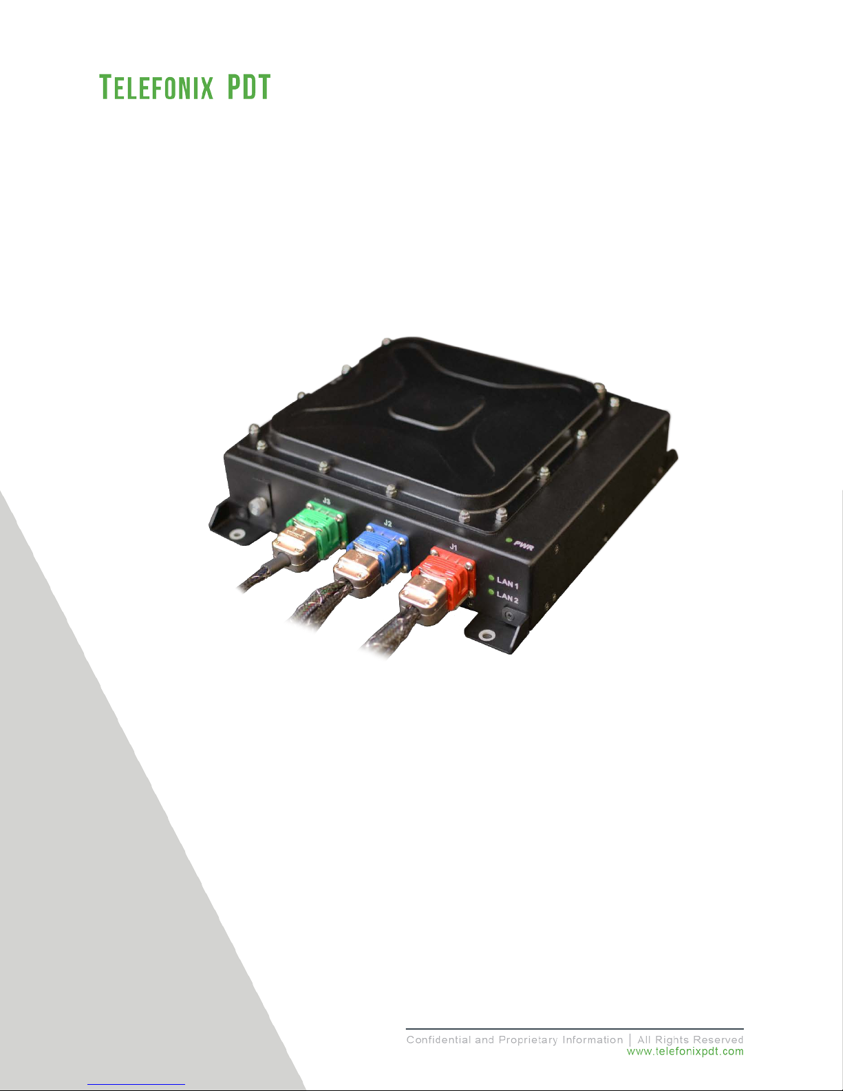
Cabin Ace-2™
User’s Manual
Version 1.0.3
THIS DOCUMENT IS THE SOLE PROPERTY OF TELEFONIX, INCORPORATED AND SHALL NOT BE REPRODUCED, COPIED OR ISSUED AS
THE BASIS OF MAINTENANCE OR SALE OF APPARATUS WIHTOUT PERMISSION OF TELEFONIX, INCORPORATED.
Inflight Entertainment and Connectivity Systems

Copyright
© Copyright 2017 Telefonix, Inc. Telefonix PDT trademarks include , Cabin Ace-2™, Cabin Ace™,
Cabin Pinnacle™, Cabin Vista™, Edge ™, All rights reserved. All other trademarks are the property of their
respective owners.
Open Source Code
This product includes code licensed under GNU General Public License, and/or certain other open source
licenses.
FCC COMPLIANCE STATEMENT
CAUTION: Changes or modifications not expressly approved could void your authority to use this
equipment
This device complies with Part 15 of the FCC Rules. Operation to the following two conditions: (1) This
device may not cause harmful interference, and (2) this device must accept any interference received,
including interference that may cause undesired operation
INDUSTRY CANADA STATEMENT
This device complies with Industry Canada licence-exempt RSS standard(s). Operation is subject to the
following two conditions: (1) this device may not cause interference, and (2) this device must accept any
interference, including interference that may cause undesired operation of the device.
Le présent appareil est conforme aux CNR d'Industrie Canada applicables aux appareils radio exempts de
licence. L'exploitation est autorisée aux deux conditions suivantes : (1) l'appareil ne doit pas produire de
brouillage, et (2) l'utilisateur de l'appareil doit accepter tout brouillage radioélectrique subi, même si le
brouillage est susceptible d'en compromettre le fonctionnement.
2 of 48
Revision Date | July 10, 2017 || Document Number | UM-E71-308-01 || Rev C

TABLE OF CONTENTS
1 User Information .................................................................................................................................... 5
1.1 Support Documentation ................................................................................................................ 5
1.2 Industry Standards ........................................................................................................................ 6
1.3 Warranty ........................................................................................................................................ 6
1.4 Exclusion of Liability Notice ........................................................................................................... 6
2 Important Safety Instructions ................................................................................................................ 7
3 Introduction ............................................................................................................................................ 8
3.1 Product Description ....................................................................................................................... 8
3.2 Hardware Architecture .................................................................................................................. 8
3.3 Key Hardware Components .......................................................................................................... 9
3.4 Orderable Part Numbers ............................................................................................................. 10
4 Starting Up .......................................................................................................................................... 12
4.1 Power Up ..................................................................................................................................... 12
4.2 Startup process ........................................................................................................................... 12
4.3 IP Strapping Table ...................................................................................................................... 16
4.4 Connecting using the Console Port ............................................................................................ 16
4.5 Connecting using Web-based GUI ............................................................................................. 18
4.6 Virtual Controller Architecture ..................................................................................................... 20
4.7 WLAN Setup................................................................................................................................ 23
5 Physical I/O ......................................................................................................................................... 28
5.1 Connections and Cabling ............................................................................................................ 28
5.2 Maintenance Connectors ............................................................................................................ 30
5.3 Status Indicators ......................................................................................................................... 30
6 Performance Data ............................................................................................................................... 32
6.1 Radio Characteristics .................................................................................................................. 32
6.2 RF Performance Table ................................................................................................................ 33
6.3 Country Codes ............................................................................................................................ 34
6.4 RF testing .................................................................................................................................... 36
7 Technical Data .................................................................................................................................... 39
7.1 Electrical and Environmental Specifications ............................................................................... 39
7.2 Mechanical Design and Dimensions ........................................................................................... 42
7.3 Grounding and Bonding .............................................................................................................. 46
7.4 Workmanship .............................................................................................................................. 46
7.5 Safety .......................................................................................................................................... 46
7.6 Protective Devices ...................................................................................................................... 46
8 Reliability and Maintainability .............................................................................................................. 47
8.1 Reliability ..................................................................................................................................... 47
8.2 Maintainability.............................................................................................................................. 47
8.3 Mean Time to Repair (MTTR) ..................................................................................................... 47
8.4 Failure Detection and Fault Isolation .......................................................................................... 47
8.5 Production Testing ...................................................................................................................... 47
9 Support and Service ............................................................................................................................ 48
9.1 Technical Support ....................................................................................................................... 48
9.2 Returning Defective Equipment .................................................................................................. 48
3 of 48
Revision Date | July 10, 2017 || Document Number | UM-E71-308-01 || Rev C

Table of Tables
Table 1: Telefonix PDT Support Documentation .......................................................................................... 5
Table 2: Aruba Support Documentation ........................................................................................................ 5
Table 3: Industry Standards .......................................................................................................................... 6
Table 4: Cabin ACe-2 Orderable Part Numbers ......................................................................................... 10
Table 5: IP Strapping Table ........................................................................................................................ 16
Table 6: CWAP External Connector Interfaces........................................................................................... 28
Table 7: AP LED Operation......................................................................................................................... 30
Table 8: Radio Characteristics .................................................................................................................... 32
Table 9: 2.4GHz Maximum Conducted Output Power ................................................................................ 33
Table 10: 5GHz Maximum Conducted Output Power ................................................................................. 33
Table 11: Country Codes ............................................................................................................................ 34
Table 12: Qualification Test Matrix - Environment ...................................................................................... 39
Table 13: Qualification Test Matrix - EMI .................................................................................................... 40
Table of Figures
Figure 1: CWAP Wave 2 System Block Diagram ....................................................................................... 10
Figure 2: Cabin ACe-2 Equipment .............................................................................................................. 11
Figure 3: Example Console Output of the SIB Boot Process ..................................................................... 13
Figure 4: Example Console Output of the AP Boot Process ...................................................................... 14
Figure 5: Aruba Instant GUI Login Prompt .................................................................................................. 18
Figure 6: The Six Sections of the Aruba Instant Main GUI Page................................................................ 19
Figure 7: The System Username and Password can be changed on the Admin tab of the System Dialog
Box. ............................................................................................................................................................. 20
Figure 8: The Virtual Controller Name and Static IP Address can be set in the System Dialog Box. ........ 21
Figure 9: The Edit Access Point Dialog Box. .............................................................................................. 22
Figure 10: The Four Stages to Creating an SSID ....................................................................................... 23
Figure 11: The WLAN Settings Tab of the New WLAN Dialog Box ............................................................ 24
Figure 12: The VLAN Tab of the New WLAN Dialog Box ........................................................................... 25
Figure 13: Configuring an External RADIUS Server from the Security Tab of the New WLAN Dialog Box26
Figure 14: Configuring Firewall Rules from the Access Tab of the New WLAN Dialog Box ...................... 27
Figure 15: J1 (Pins) Connector Layout and Pin Definitions ........................................................................ 28
Figure 16: J2 (Socket) Connector Layout and Pin Definitions .................................................................... 29
Figure 17: J3 (Socket) Connector Layout and Pin Definitions .................................................................... 29
Figure 18: Azimuth test setup (top view) ..................................................................................................... 36
Figure 19: 2.45GHz Wi-Fi Average Azimuth (antennas 1, 2, 3, 4) ............................................................ 37
Figure 20: 5GHz WiFi Average Azimuth (antennas A, B, C, D) ................................................................. 38
Figure 21: CWAP Top View ........................................................................................................................ 42
Figure 22:CWAP I/O Front View ................................................................................................................. 43
Figure 23: CWAP Side View - Right ........................................................................................................... 43
Figure 24: CWAP Side View - Left .............................................................................................................. 43
Figure 25: CWAP Rear View....................................................................................................................... 44
Figure 26: CWAP Bottom View ................................................................................................................... 44
4 of 48
Revision Date | July 10, 2017 || Document Number | UM-E71-308-01 || Rev C

CMM-44-20-29
Component Maintenance Manual (CMM), CWAP, Wave 2
ATP-E71-308-01
Acceptance Test Procedure (ATP), CWAP, Wave 2
FMEA-E71-308-01
Failure Modes and Effects Analysis (FMEA), CWAP, Wave 2
QR-E71-308-01ENV (Retrofit)
Environmental Qualification Test Report, CWAP, Wave 2
Electromagnetic Interference (EMI) Qualification Test Report (QR),
CWAP, Wave 2
This User Guide describes the features supported by Aruba
setting up and configuring the Instant network.
1 User Information
This User’s Manual describes the features supported by Telefonix PDT Cabin Wireless Access Point
TM
(CWAP), Wave 2, branded as Cabin Ace-2
and provides detailed instructions for setting up and
configuring the Cabin ACe-2 wireless access point.
This guide is intended for administrators who configure and use Cabin ACe-2.
1.1 Support Documentation
In addition to this document, the following table describes Telefonix PDT support documentation:
Table 1: Telefonix PDT Support Documentation
Document Number Description
E71-308-01-OL Outline Drawing, CWAP, Wave 2
PS-E71-308-01 Product Specification, CWAP, Wave 2
QR-E71-308-01EMI (Retrofit)
Cabin ACe-2 ships with Aruba Instant firmware version 6.4.4.4-4.2.3.2_54910. The following table
describes the applicable Aruba support documentation for this firmware version.
Document Name Description
Aruba Instant 6.4.4.4-4.2.3.0
User Guide
Aruba Instant 6.4.4.4-4.2.3.0
CLI Reference Guide
5 of 48
Table 2: Aruba Support Documentation
Instant and provides detailed instructions for
This document describes the Aruba Instant command syntax
and provides information for each Command.
Revision Date | July 10, 2017 || Document Number | UM-E71-308-01 || Rev C

Cabin Equipment Interfaces, Part 1, Interfaces, Cabin
Management and Entertainment Systems - Peripherals
A set of media access control (MAC) and physical layer (PHY)
specifications for implementing wireless local area network
5, and 60 GHz frequency bands.
A set of media access control (MAC) and physical layer (PHY)
computer communication.
Environmental Conditions and Test Procedures for Airborne
178B Software Considerations in
Airborne Systems and Equipment
1.2 Industry Standards
Industry Standard Description
ARINC 628
Table 3: Industry Standards
IEE 802.11
IEE 802.3
RTCA/DO-160G
(WLAN) computer communication in the 900 MHz and 2.4, 3.6,
specifications for implementing wired local area network (LAN)
Equipment RTCA/DO-
1.3 Warranty
The Cabin ACe-2 is warranted against defects in materials and workmanship for the warranty period from
the date of shipment. The warranty does not apply to defects resulting from improper or inadequate
maintenance of handling by the buyer, unauthorized modification or misuse, operation outside of the
product’s environmental specification of improper installation or maintenance. Telefonix PDT will not be
responsible for any defects or damages to other products not supplied by Telefonix PDT that are caused
by a faulty Telefonix PDT product.
1.4 Exclusion of Liability Notice
Should the user disregard the instructions (specifically the safety instructions) in this manual and possibly
on the device, Telefonix PDT shall be exempt from legal liability for accidents.
In the event of damage to the device, which is caused by a failure to observe the instructions (specifically
the safety instructions) in this manual and possibly on the device, Telefonix PDT shall not be required to
honor the warranty, including during the warranty period, and shall be exempt from legal liability of
accidents.
6 of 48
Revision Date | July 10, 2017 || Document Number | UM-E71-308-01 || Rev C
Electrostatic boards and their components are sensitive to static electricity.
A sudden electrostatic discharge can destroy sensitive components. Proper
Keep electrostatically sensitive components in their containers, until they
2 Important Safety Instructions
The following general instructions should always be followed in order to assure the proper operation of
Cabin ACe-2, the safety of operators and the preservation of warranty coverage.
1. Avoid removing any identification plates, serial numbers or warning labels unless specifically
authorized by the manufacturer.
2. Please observe all specified dimensions required for mounting included in the Outline Drawing,
Telefonix PDT Document E71-308-01-OL.
3. When installing the Cabin ACe-2, there must be at least 1.00” free space to the left, right, top and
rear of the unit to prevent the system overheating.
4. Leave at least 3.00” of free space to the front of the unit in order to have access to the connector
interfaces to properly connect the peripherals.
5. Attach the Cabin ACe-2 firmly to a clean flat and solid mounting surface. Use proper fastening
materials suitable for the mounting surface. Ensure that the mounting surface type and the
mounting solution safely support the load of the Cabin ACe-2 and the attached components.
6. Follow the local/national regulations for grounding. A ground bonding measurement between the
Cabin ACe-2 and the mounting surface should be conducted to ensure proper safety and EMI
characteristics are maintained.
7. The voltage feeds must not be overloaded. Adjust the cabling and external overcharge protection
to correspond with the electrical data indicated on the type label. For detailed interconnection of
power and signal wiring, refer to the Section 4 (Starting Up) and Section 5 (Physical I/O).
8. Electrostatic Discharge (ESD)
Therefore, care must be taken during all handling operations and inspection
of this product, in order to ensure product integrity at all times. Do not handle
this product out of its protective enclosure while it is not used for operational
purposes unless it is otherwise protected.
packaging and grounding rules must be observed. Always take the following
precautions.
•
arrive at an electrostatically protected workplace.
• Only touch electrostatically sensitive components when you are properly
earthed.
• Store electrostatically sensitive components in protective packaging or
on anti-static mats.
7 of 48
Revision Date | July 10, 2017 || Document Number | UM-E71-308-01 || Rev C

3 Introduction
3.1 Product Description
The Telefonix, Inc. Cabin Wireless Access Point (CWAP) is a network distribution system designed
specifically for commercial aircraft applications. The CWAP supports IEEE 802.11ac, Wave 2 functionality,
and is backwards compatible with 802.11a/b/g/n. The CWAP leverages the use of a COTS wireless access
point to facilitate wireless communications to wireless client radios in the aircraft cabin, as well as other
devices on the network. The CWAP provides a bridge between IEEE 802.3 wired Ethernet LANs and IEEE
802.11a/b/g/n/ac compliant wireless networks.
The unit is provided with aircraft level discrete inputs and outputs to facilitate event notification to and from
other aircraft systems, including remote management of the ON/OFF function. The unit is equipped with an
aircraft grade AC power supply capable of operating from 115VAC, 360 Hz – 800 Hz power with a 200
millisecond hold-up capability for power interruptions. The CWAP does not require active cooling system.
The unit communicates to a host server by physical connection over a Gigabit Ethernet wired interface
either in a “Daisy chain” or “Star” network topology environment.
This Product Specification pertains to a CWAP with integrated antennas supporting both 2.4GHz and 5GHz
bands.
This unit is identified as Telefonix PDTP/N: E71-308-01 and is branded as Cabin Ace-2
TM
.
3.2 Hardware Architecture
The CWAP leverages a state-of-the-art, commercial enterprise-class Wireless Access Point (AP). The AP
selected for this application is manufactured by Aruba Networks, a Hewlett Packard Enterprise company,
The Aruba model IAP-325 has been ruggedized and repackaged to meet the operational requirements of
commercial aircraft environment. The CWAP meets the electrical and mechanical requirements of ARINC
628.
The Cabin ACe-2 feature set includes:
• IEEE 802.11ac, Wave 2 based architecture.
• Dual radios for 2.4GHz and 5.8GHz (all U-NII channelization) simultaneous operation.
• 4x4 SU-MIMO, 4 spatial stream operation.
• 3x3 MU-MIMO, 3 spatial stream operation.
• Integrated antennas with adaptive beam forming for enhanced throughput capabilities
• Support for up to 255x associated clients devices per radio and 16x BSSID per radio
• Fully autonomous without requiring a separate wireless controller
• Support for World Wide (-WW) operation via the CLI which can automatically configure the CWAP
in accordance with location information (provided by the aircraft) to pre-set regulatory domains
(country codes) stored within the CWAP
• Discrete Inputs to control remote ON/OFF and RF Enable
• Discrete output for PSU and AP status
• IP Address strapping bits
• Support for input power pass thru to downstream CWAPs
• Aircraft grade AC power supply unit with 200 milliseconds of hold-up capacity
8 of 48
Revision Date | July 10, 2017 || Document Number | UM-E71-308-01 || Rev C

• Support for pass thru Ethernet to downstream CWAPs
• Redundant power supply (on SIB) to support Ethernet by-pass in the event of a CWAP power
supply failure
• Lightweight and compact electro-mechanical packaging
• Connectors:
o EN4165 style connectors for all I/O (per ARINC 628)
o Micro USB for serial console connection
3.3 Key Hardware Components
The CWAP key hardware components include:
• Commercial Aruba AP “engine” with integrated antennas
• Signal Interface Board (SIB)
• Main AC/DC Power Supply Unit (PSU 1)
• SIB AC/DC Power Supply Unit (PSU 2)
• External connectors Interface for Power, Ethernet, Discrete I/O (per ARINC 628)
• Mechanical Housing per ARINC 628
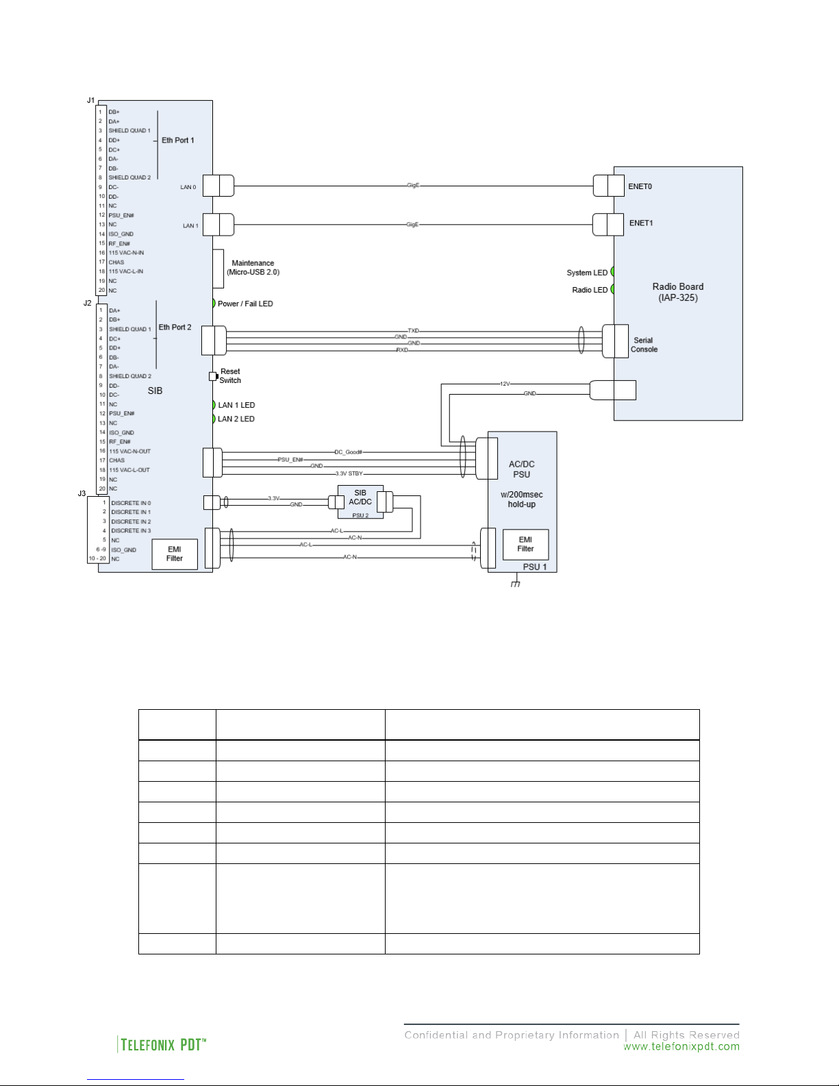
Figure 1 shows the CWAP System Block Diagram.
(Intentionally Left Blank)
9 of 48
Revision Date | July 10, 2017 || Document Number | UM-E71-308-01 || Rev C
3
E54-332
Cable Assy, Power/Signal/GbE, CWAP (J2)
4
E54-333
Cable Assy, Discretes, CWAP (J3)
5
E54-319
Cable Assy, AC Power Disconnect
6
E54-345
DB-9 Loop-back Test Connector (J1)
Assmann WSW
equivalent
USB Type B Male
8
E54-352
Cable Assy, Daisy chain
3.4 Orderable Part Numbers
10 of 48
Figure 1: CWAP Wave 2 System Block Diagram
Table 4: Cabin ACe-2 Orderable Part Numbers
ID Telefonix P/N Description
1 E71-308-01 LRU, CWAP Wave 2
2 E54-331 Cable Assy, Power/Signal/GbE, CWAP (J1)
7
Components P/N
AK67421-5 or
USB Type A Male to MicroCable
Revision Date | July 10, 2017 || Document Number | UM-E71-308-01 || Rev C
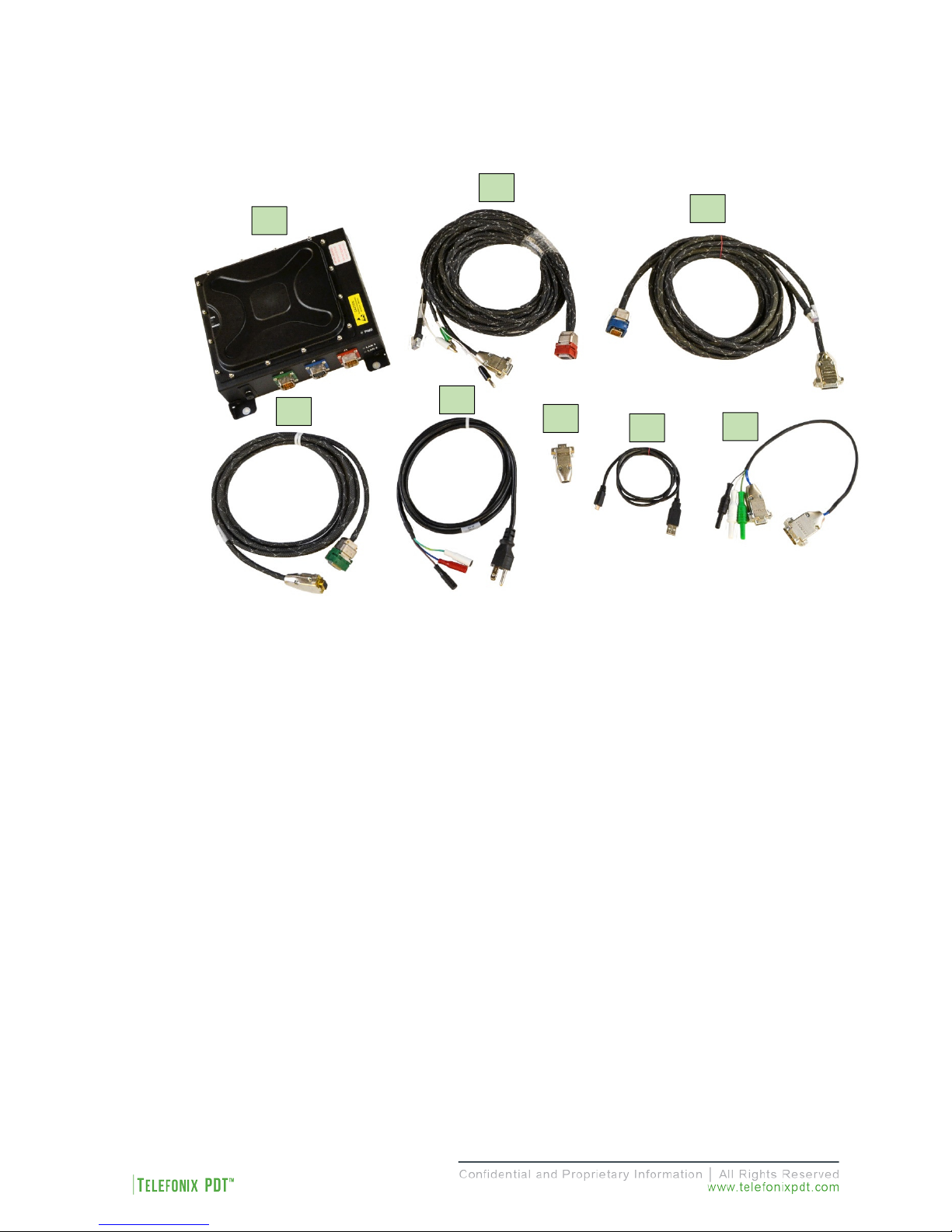
1 2 3 4 5 6 7
8
Note: Items 2 – 6 are available for test purpose and are not intended to be used in flight.
Figure 2: Cabin ACe-2 Equipment
11 of 48
Revision Date | July 10, 2017 || Document Number | UM-E71-308-01 || Rev C
AC power disconnect,
4 Starting Up
4.1 Power Up
The J1 power cable assembly, Telefonix PDT P/N E54-331, and DB-9 loop-back connector, Telefonix PDT
P/N E54-345, are required to be connected to the Cabin ACe-2 to turn on when power is applied.
WARNING!
The specified voltage input range is 97 to 134 VAC, 60 – 800 Hz, singlephase power.
DO NOT connect to 220 VAC.
The power source must supply a minimum of 20W.
The power source must be switched off via
Telefonix PDTP/N E54-319, and must be easily accessible.
Ambient temperature must be above -20 °C for the CWAP to turn on.
Power is not switched internally and the unit will boot up as soon as
power is applied.
Properly connect Telefonix PDT P/N E54-331 to the CWAP J1 connector. The power source must be
switched off via AC Power disconnect, Telefonix PDT P/N E54-319, to make sure that no voltage is present
at the terminal during the connecting procedure. Plug the DB-9 loopback connector, Telefonix PDT P/N
E54-345, to the mating connector of J1, E54-331 cable assembly.
Connect the other end of the power cord to the power source (not provided). Switch on the power source
via the AC power disconnect.
4.2 Startup process
The CWAP needs two IP addresses for network connectivity, one for the access point and one for the
Signal Interface Board (SIB). The four discrete IP strapping pins in the J3 connector are set to HIGH (+5v
DC) by pull up resistors, and can be grounded to set static IP addresses, by default the CWAP is configured
as a DHCP client, and will request two IP address from the network DHCP server. If no DHCP server
responds to the request then auto configuration will assign an address to the AP on the 169.254.0.0
255.255.0.0 network (the SIB will continue to send DHCP requests).
Note: The IP strapping bits are read by the CWAP at power up and will over-write any static IP assignment
made in the Aruba GUI. This behavior persists even when interface J3 is not connected.
12 of 48
Revision Date | July 10, 2017 || Document Number | UM-E71-308-01 || Rev C
4.2.1 Boot Up
4.2.1.1 SIB Boot Up
The SIB runs both the bootloader and application firmware components upon powering on the unit. There
is a two (2) second delay before the firmware loads to allow the bootloader to check for the presence of a
SIB firmware upgrade.
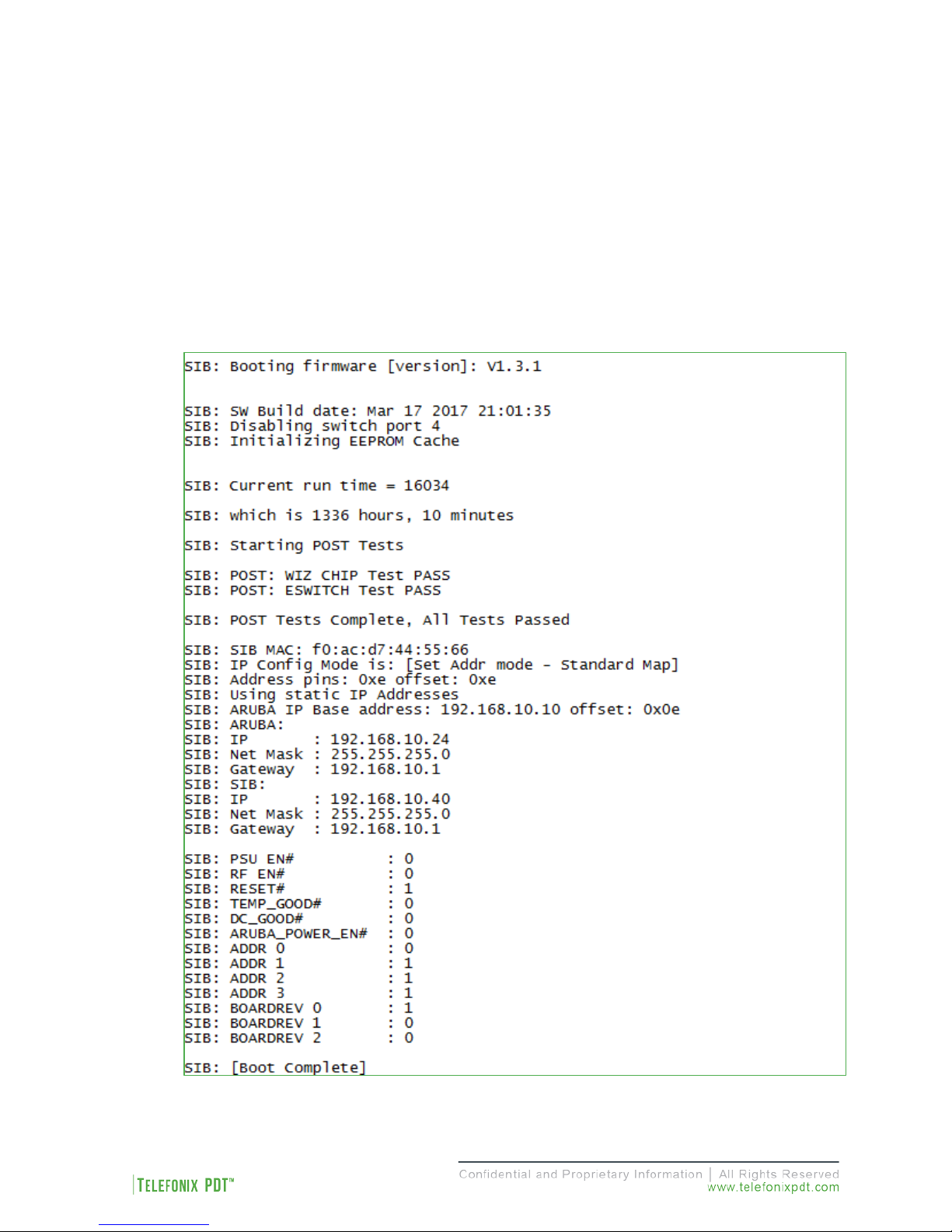
During startup, the firmware performs a Power On Self-Test (POST), queries the discrete pins, and reads
the SIB configuration and manufacturing data from an internal EEPROM. After the boot process completes
there is a five (5) second window in which you may be asked to enter SIB command mode by your technical
service representative. The console output of the SIB boot process is shown in Figure 3, the [Boot
Complete] prompt indicates the beginning of the five (5) second delay.
Figure 3: Example Console Output of the SIB Boot Process
13 of 48
Revision Date | July 10, 2017 || Document Number | UM-E71-308-01 || Rev C
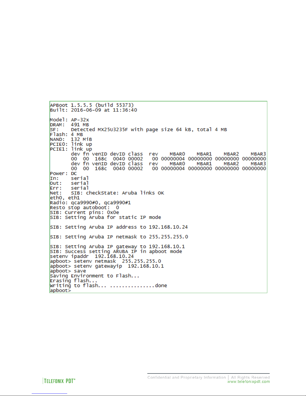
4.2.1.2 Access Point (AP) Boot
Following SIB boot, the firmware boots the Aruba AP. During startup, the AP provides an auto-boot
countdown prompt that allows you to interrupt the normal startup process and access apboot mode. The
SIB firmware uses this mode to set the IP address configuration as defined by the IP strapping pins, then
starts a ten (10) second inactivity counter to allow user access to apboot.
The console output of the AP boot process is shown in Figure 4, the apboot> prompt indicates the
beginning of the ten (10) second counter.
Figure 4: Example Console Output of the AP Boot Process
14 of 48
Revision Date | July 10, 2017 || Document Number | UM-E71-308-01 || Rev C

While in apboot mode you have access to the following commands:
? - alias for 'help'
boot - boot the OS image
clear - clear the OS image or other information
date - get/set/reset date & time
dhcp - invoke DHCP client to obtain IP/boot params
factory_reset - reset to factory defaults
help - print online help
mfginfo - show manufacturing info
ping - send ICMP ECHO_REQUEST to network host
printenv - print environment variables
purgeenv - restore default environment variables
reset - Perform RESET of the CPU
saveenv - save environment variables to persistent storage
setenv - set environment variables
tftpboot - boot image via network using TFTP protocol
upgrade - upgrade the APBoot or OS image
version - display version
The setenv command can be used to set the environment variables listed below. Enter commands one per
line, replacing the equal sign with a space. To clear an environment variable, enter the variable name
followed by <CR>.
bootdelay=2
baudrate=9600
autoload=n
boardname=Talisker
servername=aruba-master
bootcmd=boot ap
autostart=yes
bootfile=mips32.ari
ethaddr=d8:c7:c8:XX:XX:XX
os_partition=0
ethact=eth0
gatewayip=192.168.1.1
netmask=255.255.255.0
dnsip=8.8.8.8
name=IAP105
domainname=arubanetworks.com
ipaddr=192.168.1.101
stdin=serial
stdout=serial
stderr=serial
15 of 48
Revision Date | July 10, 2017 || Document Number | UM-E71-308-01 || Rev C
 Loading...