

Page 1

RTL8676 11N ADSL2+ Wireless Router
User Manual
Page 2

i
Contents
1 Introduction ........................................................................................................1
1.1 Packing List...........................................................................................1
1.2 Safety Precautions ................................................................................1
1.3 LEDs and Interfaces..............................................................................2
1.4 System Requirements ...........................................................................4
1.5 Features ................................................................................................4
2 Hardware Installation .........................................................................................6
3 Web Configuration .............................................................................................8
3.1 Accessing the Device............................................................................8
3.2 Setup ...................................................................................................13
3.2.1 Wizard.......................................................................................13
3.2.2 Internet Setup...........................................................................19
3.2.3 Wireless....................................................................................22
3.2.4 Local Network...........................................................................28
3.2.5 Time and Date..........................................................................32
3.2.6 Logout.......................................................................................32
3.3 Advanced.............................................................................................33
3.3.1 Advanced Wireless...................................................................33
3.3.2 Port Forwarding........................................................................41
3.3.3 DMZ..........................................................................................44
3.3.4 SAMBA.....................................................................................45
3.3.5 3G WAN Configuration.............................................................46
3.3.6 Parental Control........................................................................51
3.3.7 Filtering Options........................................................................54
3.3.8 QoS Configuration....................................................................59
3.3.9 Firewall Settings .......................................................................64
3.3.10 DNS.....................................................................................65
3.3.11 Dynamic DNS......................................................................65
3.3.12 Network Tools...................................................................... 67
3.3.13 Routing................................................................................78
3.3.14 Schedules............................................................................82
3.3.15 DLNA...................................................................................83
3.3.16 Logout .................................................................................83
3.4 Management........................................................................................84
Page 3

ii
3.4.1 System Management................................................................84
3.4.2 Firmware Update......................................................................85
3.4.3 Access Controls........................................................................86
3.4.4 Diagnosis..................................................................................89
3.4.5 Log Configuration .....................................................................92
3.4.6 Logout.......................................................................................93
3.5 Status...................................................................................................94
3.5.1 Device Info................................................................................94
3.5.2 Wireless Clients........................................................................96
3.5.3 DHCP Clients............................................................................96
3.5.4 Logs..........................................................................................96
3.5.5 Statistics....................................................................................97
3.5.6 Route Info.................................................................................98
3.5.7 Logout.......................................................................................99
3.6 Help .....................................................................................................99
Page 4

User Manual
1
1 Introduction
The device supports multiple line modes. With four 10/100 base-T Ethernet
interfaces at the user end, the device provides high-speed ADSL broadband
connection to the Internet or Intranet for high-end users like net bars and office
users. It provides high performance access to the Internet with a downstream
rate of 24 Mbps and an upstream rate of 1 Mbps. It supports 3G WAN, 3G
backup, and Samba for USB storage.
The device supports WLAN access, such as WLAN AP or WLAN device, to the
Internet. It complies with specifications of IEEE 802.11, 802.11b/g/n, WEP, WPA,
and WPA2 security. The WLAN of the device supports 2T2R.
1.1 Packing List
1 x device
1 x external splitter
1 x power adapter
2 x telephone cables
1 x Ethernet cable
1.2 Safety Precautions
Take the following instructions to prevent the device from risks and damage
caused by fire or electric power:
Use the type of power marked in the volume label.
Use the power adapter in the product package.
Pay attention to the power load of the outlet or prolonged lines. An
overburden power outlet or damaged lines or plugs may cause electric
shock or fire accidents. Check the power cords regularly. If you find any
damage, replace it at once.
Proper space left for heat dissipation is necessary to avoid damage
caused by overheating to the device. The long and thin holes on the device
are designed for heat dissipation to ensure that the device works normally.
Do not cover these heat dissipation holes.
Page 5

User Manual
2
Do not put this device close to a heat source or under a high temperature
occurs. Keep the device away from direct sunshine.
Do not put this device close to an overdamp or watery place. Do not spill
fluid on this device.
Do not connect this device to a PC or electronic product unless instructed
by our customer engineer or your broadband provider. Wrong connection
may cause power or fire risk.
Do not place this device on an unstable surface or support.
1.3 LEDs and Interfaces
Front Panel
Figure 1 Front panel
The following table describes the LEDs of the device.
LED Color Status Description
Off Router powered off
Blinking 2Hz
Red
Failure on power-on self-test
Power Red/Green
Solid Green Router powered on correctly.
On Ethernet connection is available.
Ethernet Green
Off
Ethernet connection is
unavailable.
On Wi-Fi connection is available.
Off Wi-Fi connection is unavailable.
Wifi Green
Blinking
Green
Negotiation or traffic on line.
Solid Green WPS active
Blinking 2Hz
Green
WPS negotiation open
WPS Red/Green
Solid Red (20 Problems on WPS registration
Page 6
User Manual
3
LED Color Status Description
seconds)
Blinking
Green
Negotiation
Solid Green Up
Quick
Blinking
Green
Tx/Rx traffic on line
Solid Red Authentication failed
3G Red/Green
Off
Traffic through broadband
interface
Off Router powered off
Blinking 2Hz No line detected
Blinking 4Hz Line training
ADSL Green
Solid Line up
Blinking
Green
PPP/DHCP negotiation
Solid Green PPP/DHCP up
Quick
Blinking
Green
Tx/Rx traffice on line
Internet Red/Green
Solid Red Authentication failed
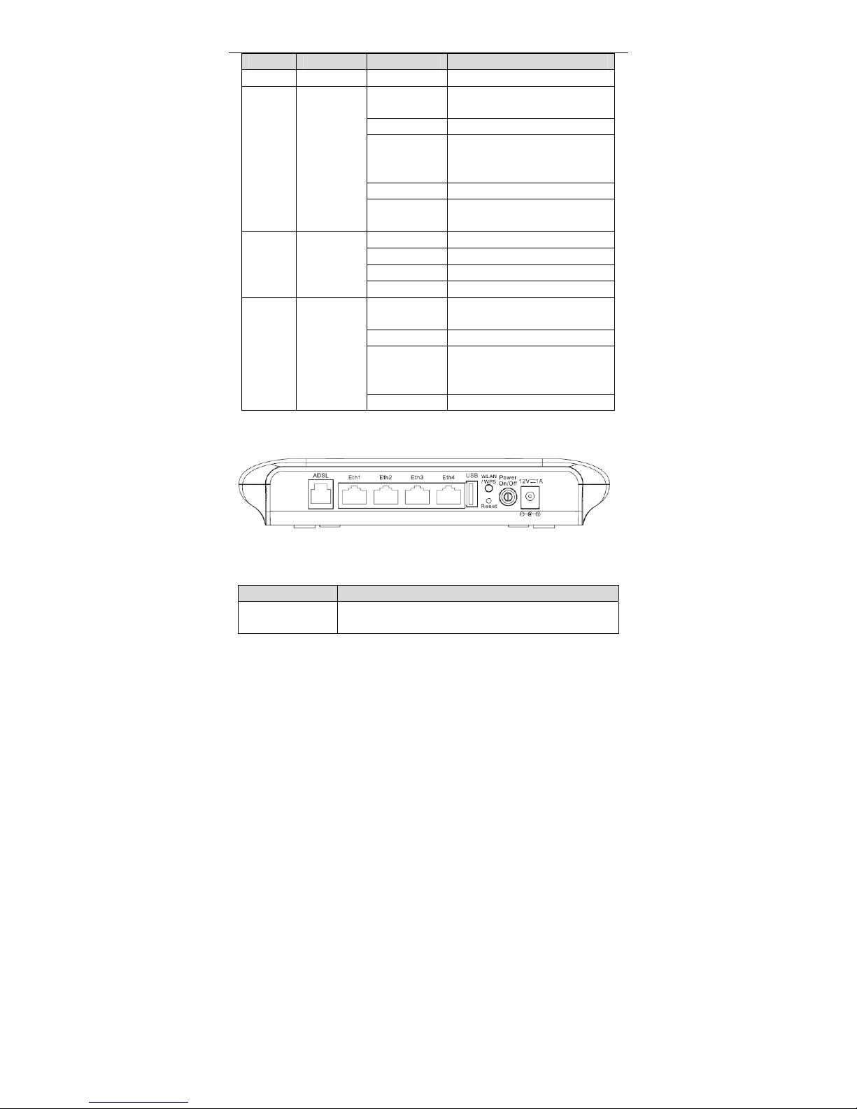
Rear Panel
Figure 2 Rear panel
The following table describes the interface of the device.
Interface/Button Description
ADSL
RJ-11 interface connecting to a telephone set through a
telephone cable
Page 7
User Manual
4
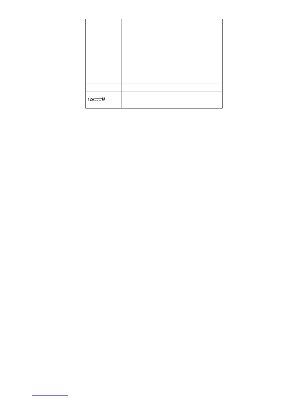
Eth1/2/3/4
Ethernet RJ-45 interfaces connecting to the Ethernet
interfaces of computers or Ethernet devices
USB Connecting to a 3G data card or other USB storage device
WLAN/WPS
Press the button for less than 1 second to enable
WLAN function.
Press the button for more than 10 seconds to enable
WPS function.
Reset
Reset to the factory defaults. To restore factory defaults,
keep the device powered on and push a paper clip into the
hole. Press down the button for more than 5 seconds and
then release.
Power On/Off Push to power on/off the device.
Interface connecting to the power adapter. The power
adapter output is: 12V DC, 800mA
1.4 System Requirements
A 10 baseT/100BaseT Ethernet card is installed on your PC.
A hub or switch (attached to several PCs through one of Ethernet
interfaces on the device)
Operating system: Windows Vista, Windows 7, Windows 98SE, Windows
2000, Windows ME or Windows XP
Internet Explorer V5.0 or higher, Netscape V4.0 or higher, or Firefox 1.5 or
higher
1.5 Features
Various line modes
External PPPoE dial-up access
Internal PPPoE and PPPoA dial-up access
Leased line mode
1483B, 1483R, and MER access
Multiple PVCs (eight at most) and these PVCs can be isolated from each
other
Page 8

User Manual
5
A single PVC with multiple sessions
Multiple PVCs with multiple sessions
Binding of ports with PVCs
802.1Q and 802.1P protocol
DHCP server
NAT and NAPT
Static route
Firmware upgrade: Web, TFTP, FTP
Reset to the factory defaults
DNS relay
Virtual server
DMZ
Two-level passwords and user names
Web user interface
Telnet CLI
System status display
PPP session PAP and CHAP
IP filter
IP QoS
Samba
Remote access control
Line connection status test
Remote management (telnet and HTTP, TR069)
Backup and restoration of configuration file
Ethernet interface supports crossover detection, auto-correction and
polarity correction
UPnP
3G WAN and 3G Backup
Samba for USB storage
Page 9
User Manual
6
2 Hardware Installation
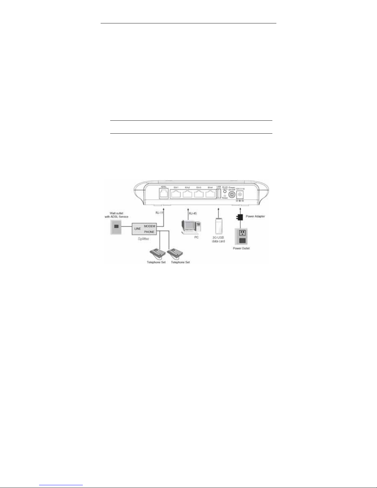
Step 1 Connect the ADSL port of the device and the Modem port of the
splitter with a telephone cable. Connect the phone to the Phone port of
the splitter through a telephone cable. Connect the incoming line to the
Line port of the splitter.
The splitter has three ports:
Line: Connect to a wall phone port (RJ-11 jack).
Modem: Connect to the DSL port of the device.
Phone: Connect to a telephone set.
Step 2 Connect an Eth port of the device to the network card of the PC
through an Ethernet cable (MDI/MDIX).
Note:
Use twisted-pair cables to connect the device to a Hub or switch.
Step 3 Plug one end of the power adapter to the wall outlet and the other end
to the Power port of the device.
Connection 1: Figure 3 displays the application diagram for the connection of
the device, PC, splitter and telephone sets, when no telephone set is placed
before the splitter.
Figure 3 Connection diagram (without telephone sets before the splitter)
Page 10
User Manual
7
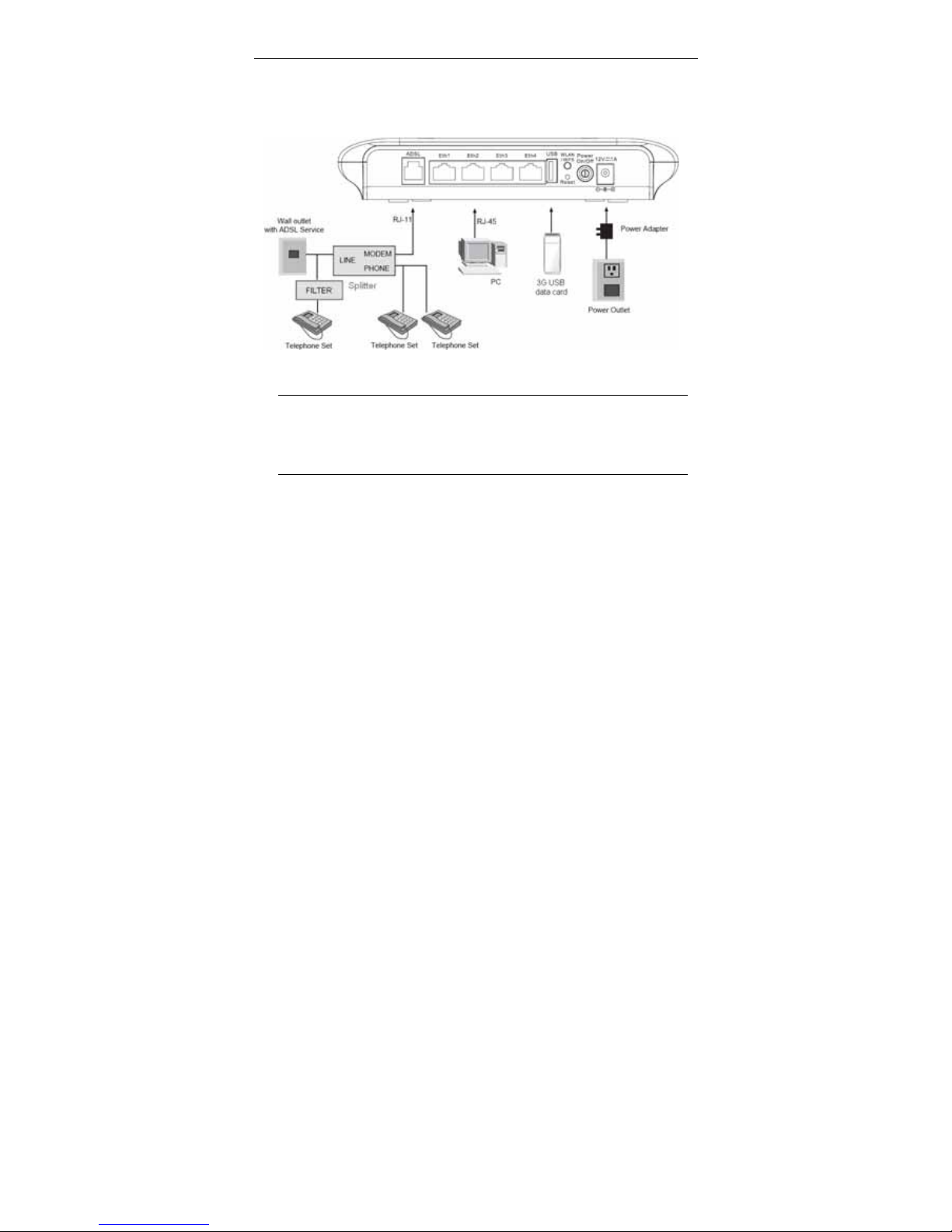
Connection 2: Figure 4 displays the application diagram for the connection of
the device, PC, splitter and telephone sets when a telephone set is placed before
the splitter.
As illustrated in the following figure, the splitter is installed close to the device.
Figure 4 Connection diagram (with a telephone set before the splitter)
Note:
When connection 2 is used, the filter must be installed close to the
telephone cable. See Figure 4. Do not use the splitter to replace the
filter.
Installing a telephone directly before the splitter may lead to failure of connection
between the device and the central office, or failure of Internet access, or slow
connection speed. If you really need to add a telephone set before the splitter,
you must add a microfilter before a telephone set. Do not connect several
telephones before the splitter or connect several telephones with the microfilter.
Page 11
User Manual
8
3 Web Configuration
This chapter describes how to configure the device by using the Web-based
configuration utility.
3.1 Accessing the Device
The following is the detailed description of accesing the device for the first time.
Step 1 Open the Internet Explorer (IE) browser and enter http://192.168.1.1
.
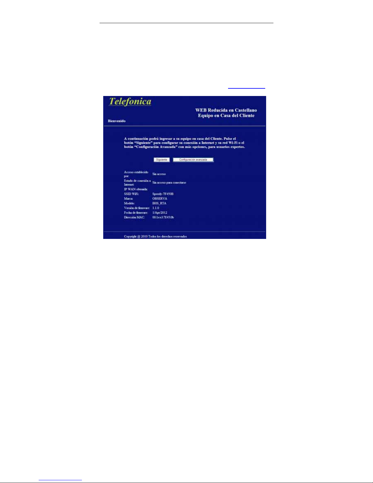
Step 2 The Welcome page shown in the following figure appears.
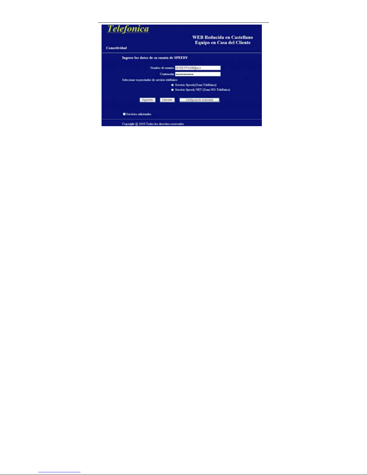
Step 3 Click Next to configure your user’s account and Wi-Fi network as
shown in the following Connectivity page, or click Advanced
Configuration for more options.
Page 12
User Manual
9
By default, the user’s name is MAC@acs and password is the MAC. The MAC is
the equipment’s MAC Address leaving out the 2 points.
Step 4 Selecte Advanced Configuration to login into the equipment with the
user admin and password 1234, or selected Cancel to return to the
Welcome page without saving changes, or select Next to save
selected changes. When the checkbox Additional Services is
selected, it will go to the following figure.
Page 13

User Manual
10
When Solo Speedy (LAN1, LAN2, LAN3 y WIFI)+ VOIP(LAN4) is selected, the
LAN4 port is used as VOIP port for voice service.
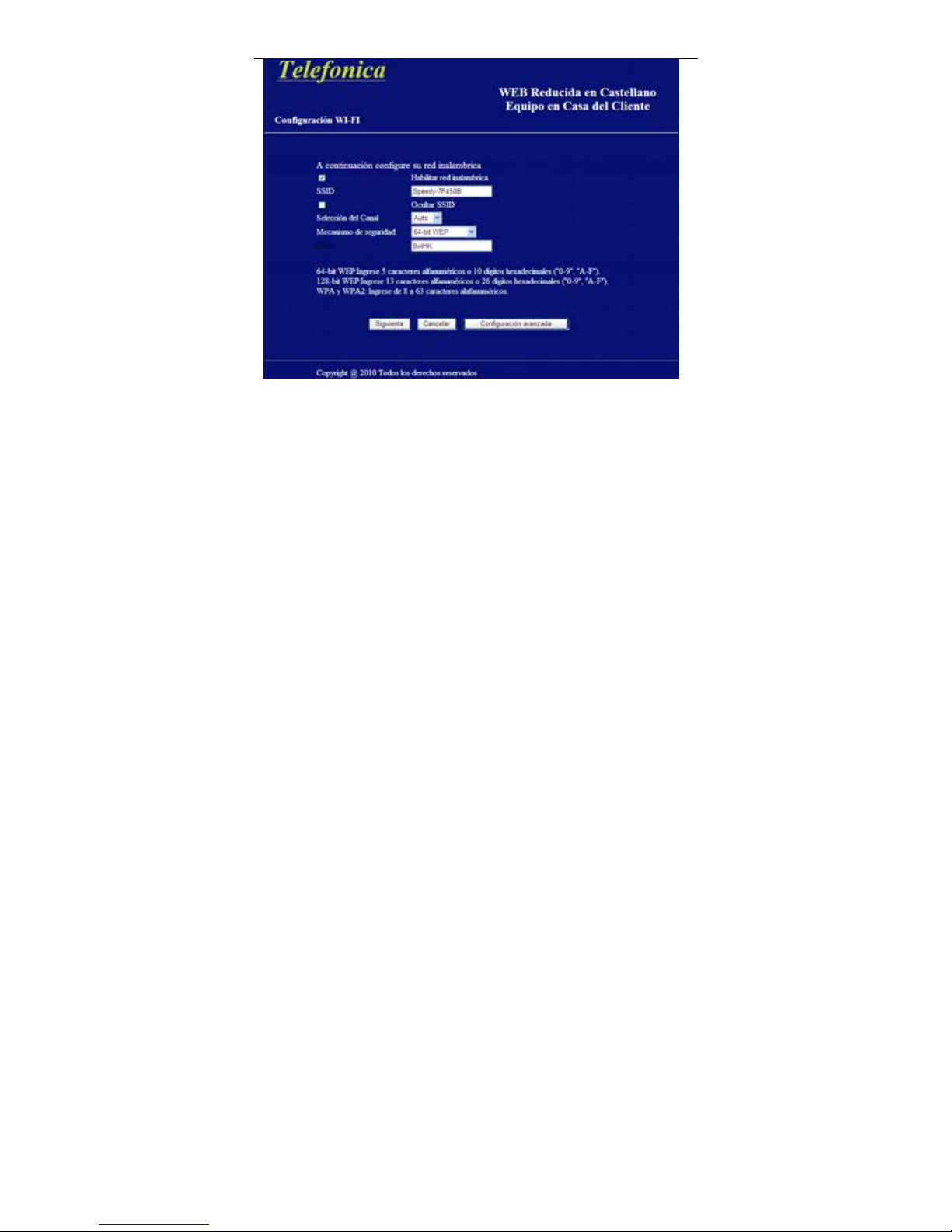
Step 5 Select Advanced Configuration to login into the equipment, or select
Cancel to return to the Connectivity page without saving the changes,
or selected Next to save changes and go to the following
WiFi-Configuration page.
Page 14
User Manual
11
Next, you are going to config you wireless network. You can enable wireless
network, hide the SSID, select a channel and security mode, and input a key as
instructed by the screen.
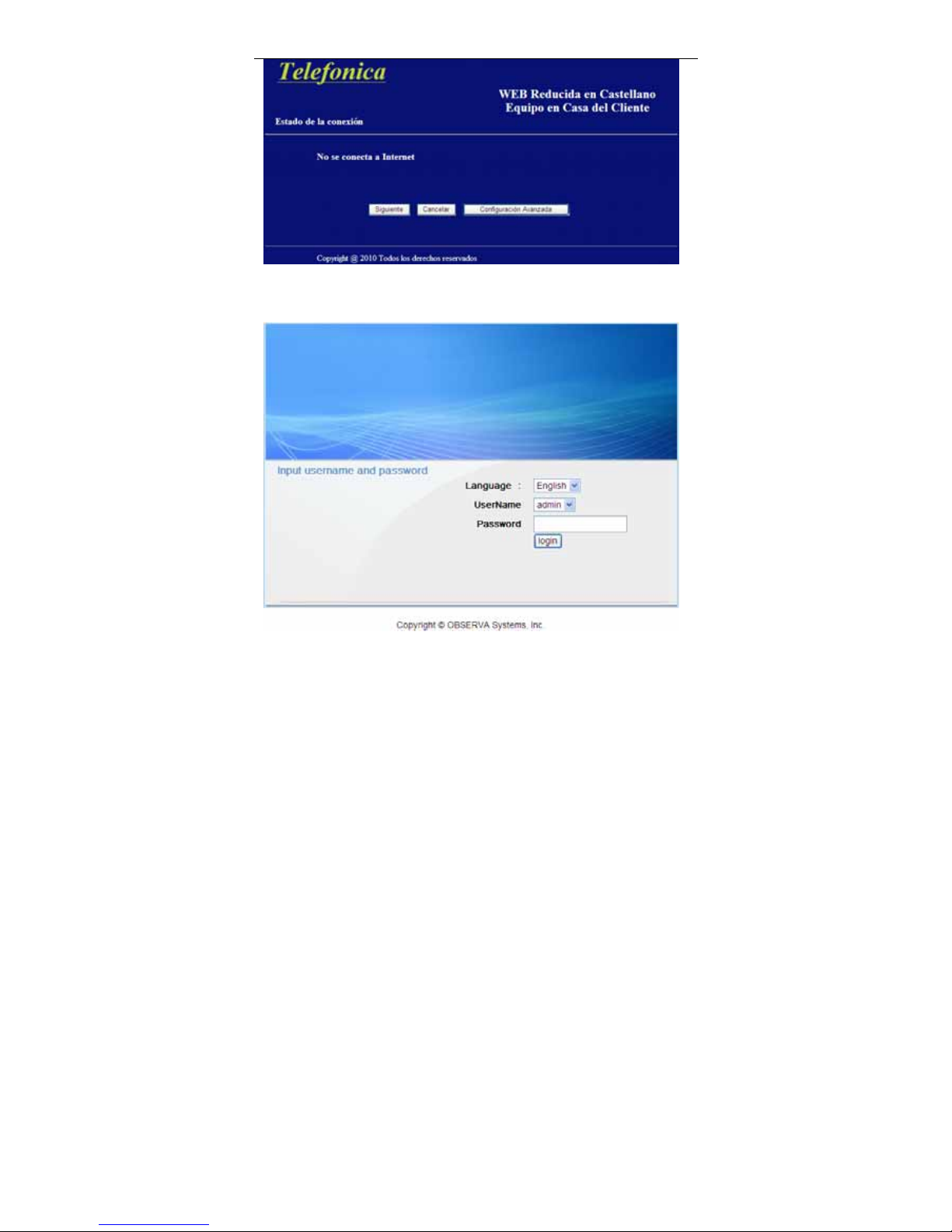
Step 6 Select Next to save changes and go to the following figure, or select
Cancel to return to the Additional Services page without saving the
changes, or select Advanced Configuration to login into the
equipment.
Page 15
User Manual
12
The Login page is shown as below. Choose the username admin, input the
password 1234 and click login.
If you log in successfully, the page shown in the following figure appears.
Page 16

User Manual
13
If the login information is incorrect, click Try Again in the page that pops up to log
in again.
3.2 Setup
In the main interface, click Setup tab to enter the Setup menu as shown in the
following figure. The submenus are Wizard, Internet Setup, Wireless, Local
Network, Time and Date and Logout.
3.2.1 Wizard
Wizard enables fast and accurate configuration of Internet connection and other
important parameters. The following sections describe configuration parameters.
When subscribing to a broadband service, you should be aware of the method,
by which you are connected to the Internet. Your physical WAN device can be
Ethernet, DSL, or both. Technical information about the properties of your
Internet connection is provided by your Internet service provider (ISP). For
example, your ISP should inform you whether you are connected to the Internet
using a static or dynamic IP address, or the protocol, such as PPPoA or PPPoE,
that you use to communicate over the Internet.
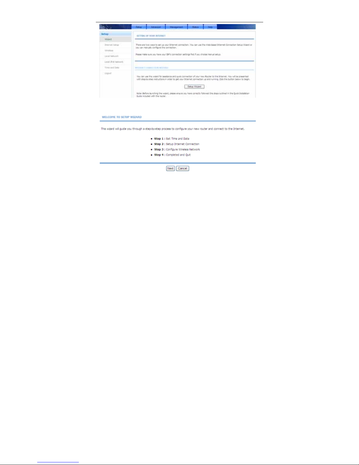
Step 1 Choose Setup > Wizard. The page shown in the following figure
appears.
Page 17
User Manual
14
Step 2 Click Setup Wizard. The page shown in the following figure appears.
Step 3 There are four steps to configure the device. Click Next to continue.
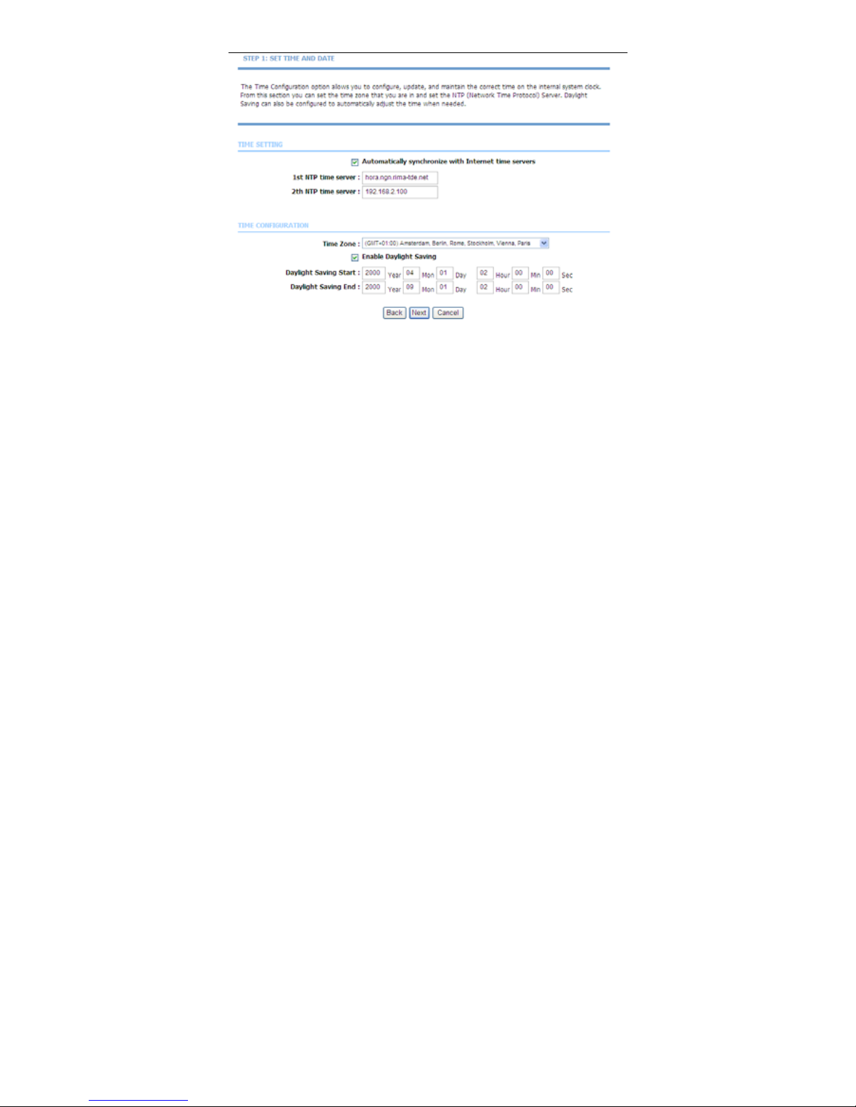
Step 4 Set the time and date.
Page 18
User Manual
15
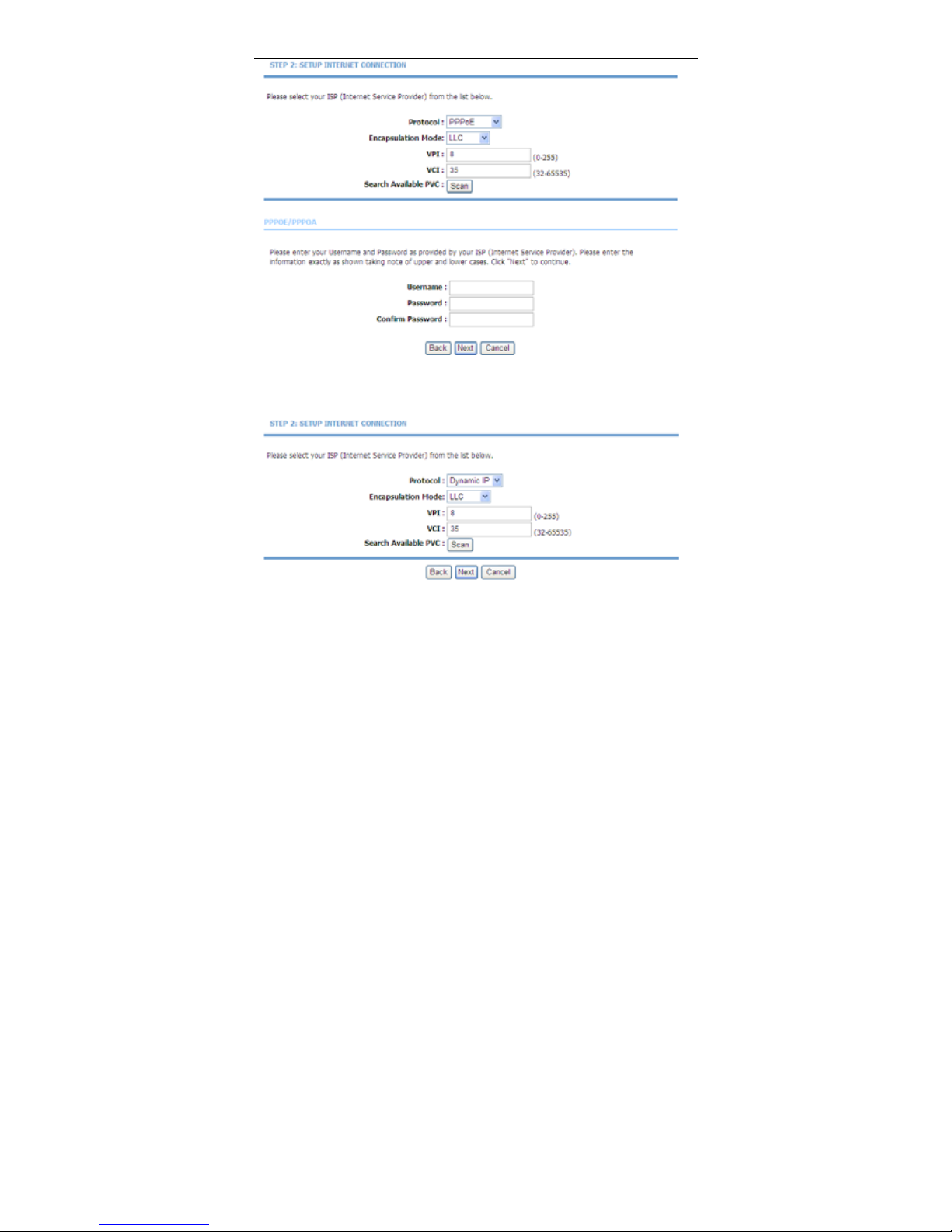
Step 5 Configure the Internet connection.
Set the VPI and VCI. If the Protocol is PPPoE or PPPoA, the page shown in the
two following figure appears.
Page 19
User Manual
16
In this page, enter the user name and password as provided by your ISP.
If the Protocol is Dynamic IP, the page shown in the following figure appears.
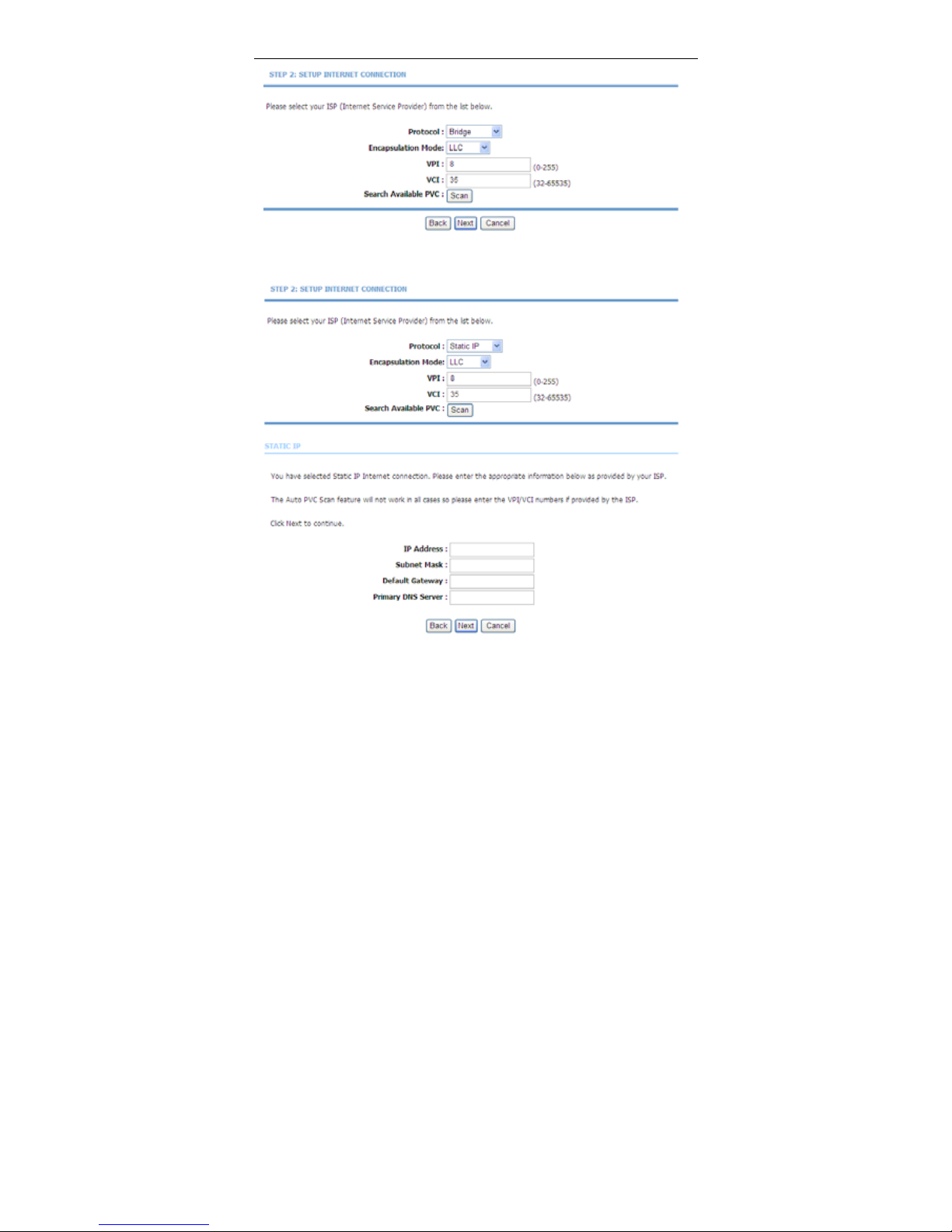
If the Protocol is Bridge, the page shown in the following figure appears.
Page 20
User Manual
17
If the Protocol is Static IP, the page shown in the following figure appears.
Enter the IP Address, Subnet Mask, Default Gateway and Primary DNS
Server. Click Next. The page shown in the following figure appears.
Page 21
User Manual
18
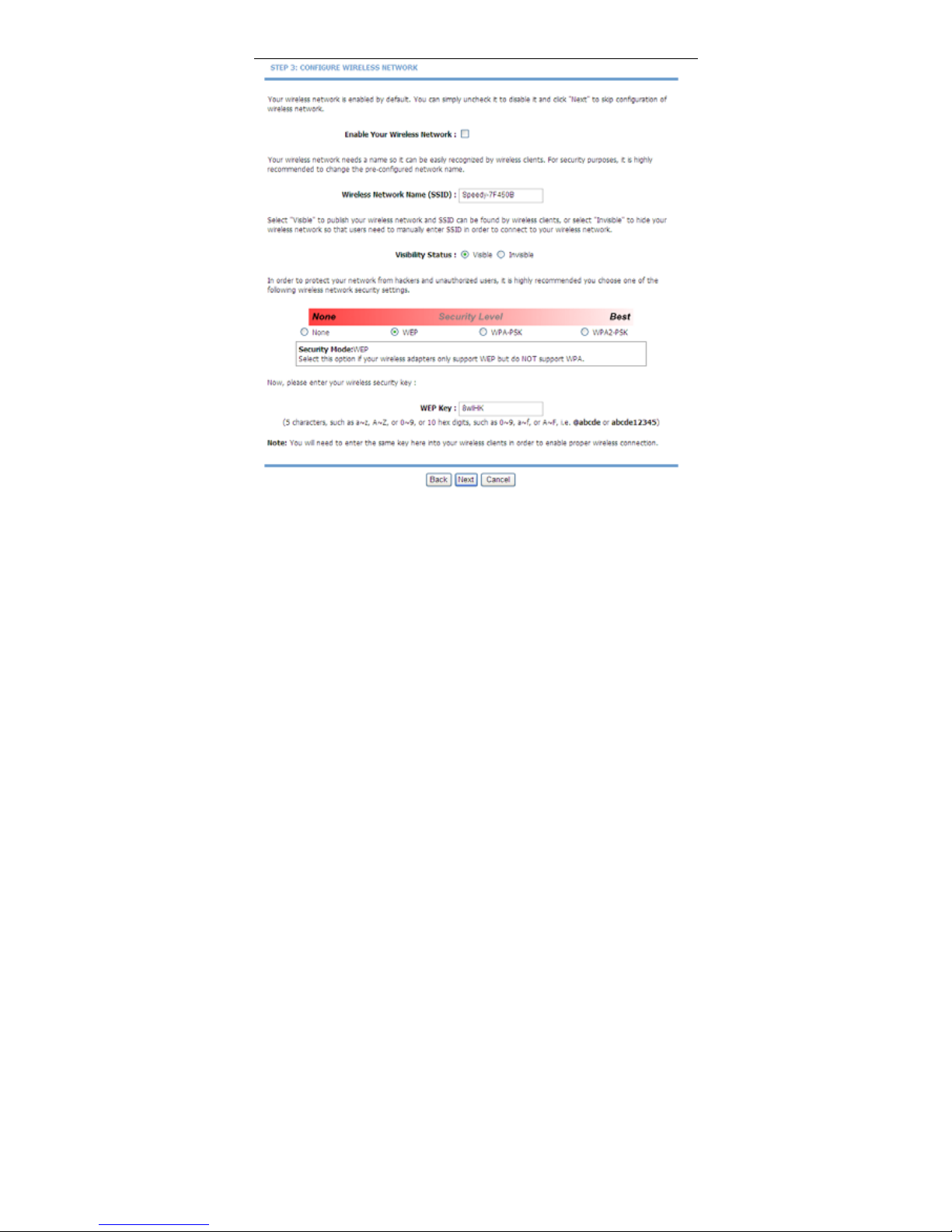
Step 6 Configure the wireless network. Enter the information and click Next.
Page 22
User Manual
19
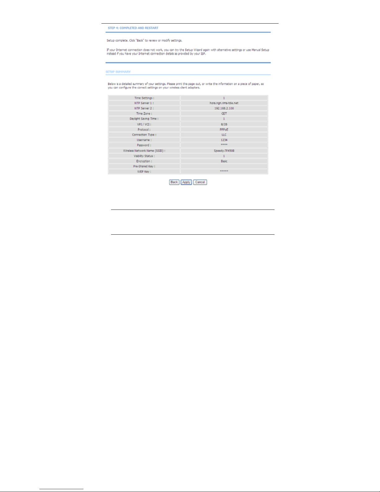
Step 7 Click Apply to save the settings.
Note:
In each step of the Wizard page, you can click Back to review or
modify the previous settings. Click Cancel to exit the wizard page.
3.2.2 Internet Setup
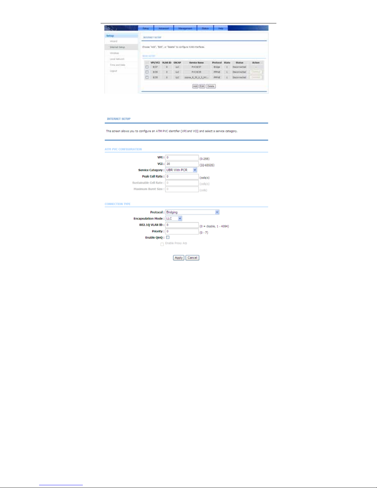
Choose Setup > Internet Setup. The page shown in the following figure appears.
In this page, you can configure the WAN interface of the device.
Page 23
User Manual
20
Click Add in “INTERNET SETUP”. The page shown in the following figure
appears.
Page 24
User Manual
21
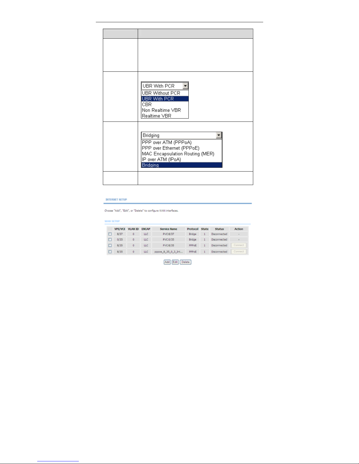
The following table describes the parameters in this page.
Field
Description
PVC Settings
VPI: The virtual path between two points in an ATM
network, and its valid value is from 0 to 255.
VCI: The virtual channel between two points in an ATM
network, ranging from 32 to 65535 (0 to 31 is reserved
for local management of ATM traffic).
Service
Category
You can select from the drop-down list.
Protocol
You can select from the drop-down list.
Encapsulation
Mode
Select the method of encapsulation provided by your
ISP. You can select LLC or VCMUX.
Click Apply, the page shown in the following figure appears.
Page 25
User Manual
22
3.2.3 Wireless
This section describes the wireless LAN and basic configuration. A wireless LAN
can be as simple as two computers with wireless LAN cards communicating in a
pear-to-pear network or as complex as a number of computers with wireless LAN
cards communicating through access points which bridge network traffic to wired
LAN.
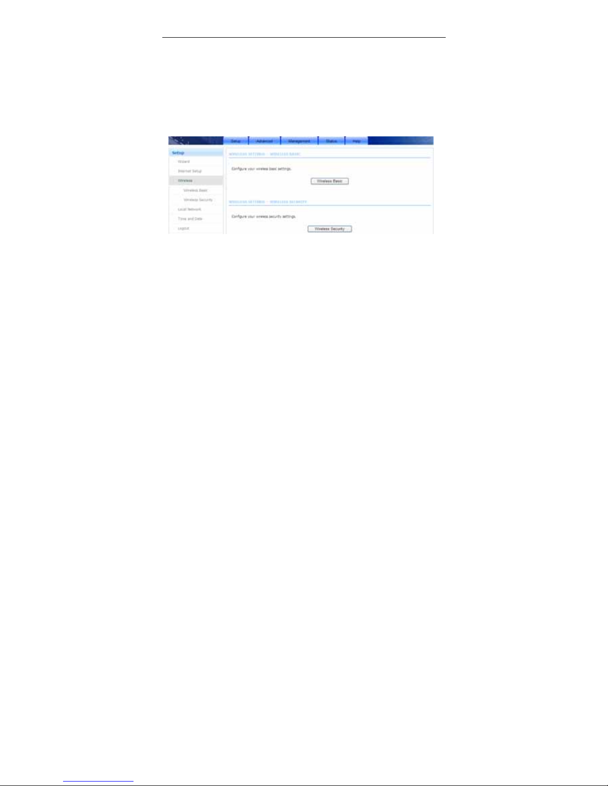
Choose Setup > Wireless. The Wireless page shown in the following figure
appears.
3.2.3.1 Wireless Basic
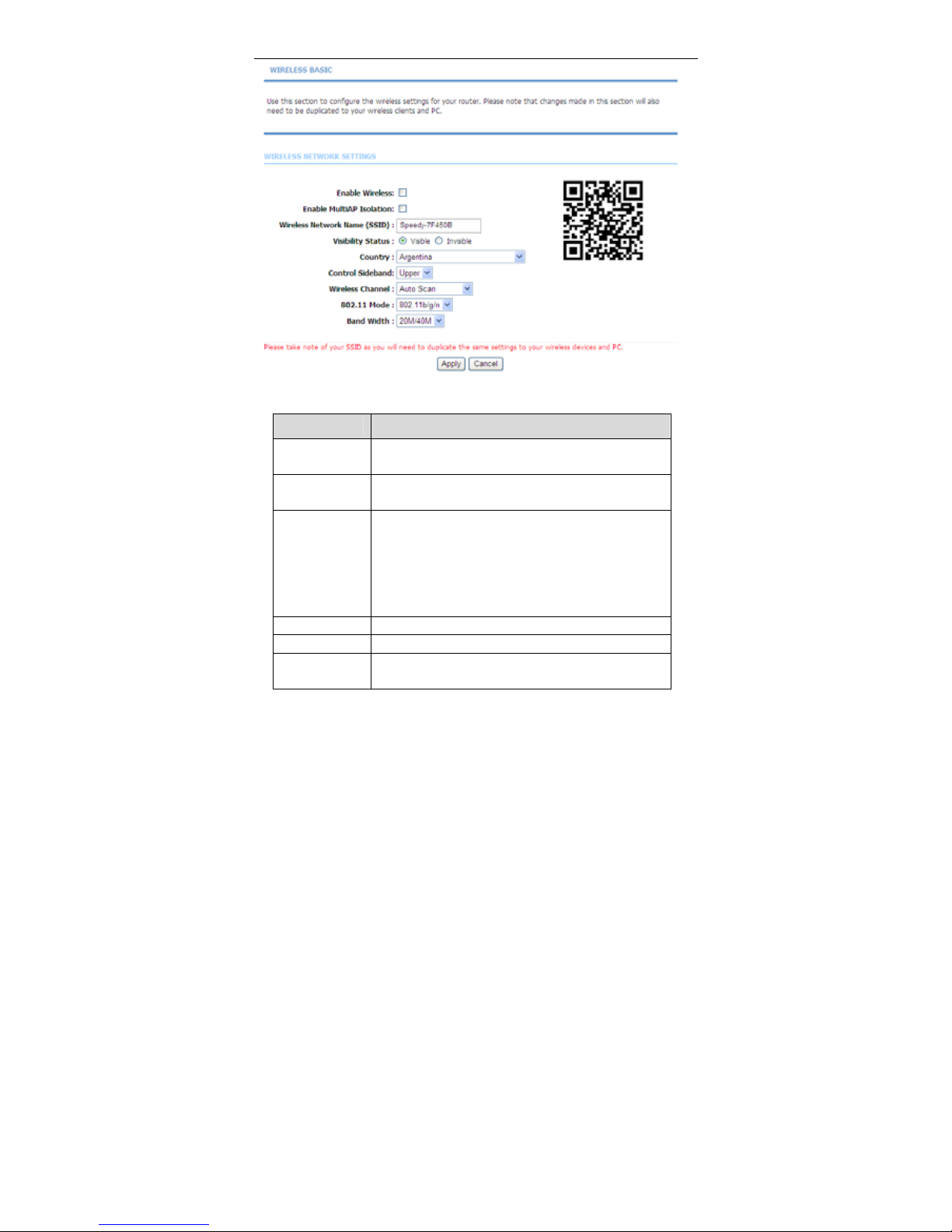
In the Wireless page, click Wireless Basic. The page shown in the following
figure appears. In this page, you can configure the parameters of wireless LAN
clients that may connect to the device.
Page 26
User Manual
23
The following table describes the parameters in this page.
Field
Description
Enable
Wireless
Select this to turn Wi-Fi on or off.
Enable MultiAP
Isolation
Select this to turn MultiAP isolation on and off.
Wireless
Network Name
(SSID)
The Wireless Network Name is a unique name that
identifies a network. All devices on a network must
share the same wireless network name in order to
communicate on the network. If you decide to change
the wireless network name from the default setting,
enter your new wireless network name in this field.
Visibility Status You can select Visible or Invisible.
Country Select the country from the drop-down list.
Control
Sideband
Choose the channel selection mode as Upper or
Lower.
Page 27

User Manual
24
Field
Description
Wireless
Channel
Select the wireless channel from the pull-down menu.
It is different for different country.
802.11 Mode
Select the appropriate 802.11 mode based on the
wireless clients in your network. The drop-down menu
options are 802.11b, 802.11g, 802.11n, 802.11b/g,
802.11n/g and 802.11b/g/n.
Band Width
Select the appropriate band of 20M, 40M or 20M/40M
from the pull-down menu.
Click Apply to save the settings.
3.2.3.2 Wireless Security
In the Wireless page, click Wireless Security. The page shown in the following
figure appears. Wireless security is vital to your network to protect the wireless
communication among wireless stations, access points and wired network.
Note:
Enable Wireless before configuring the wireless security settings in
this page. Refer to 3.2.3.1 Wireless Basic.
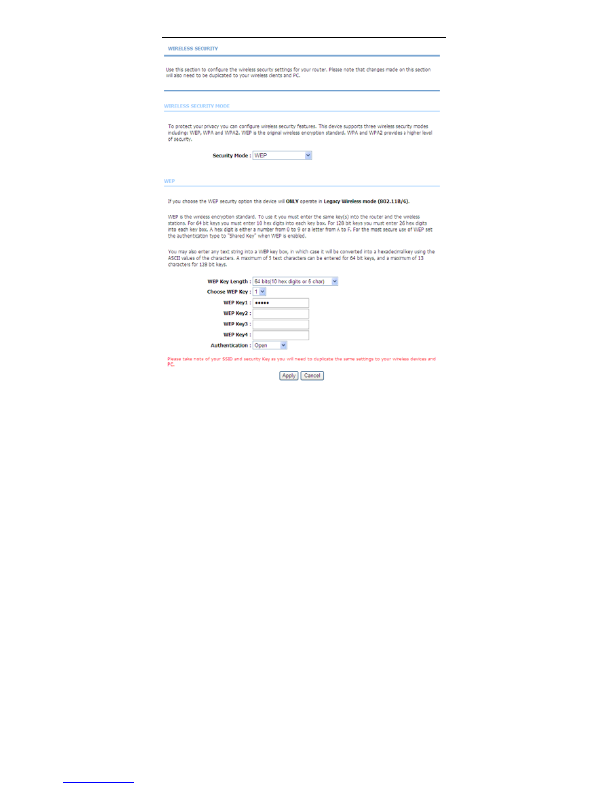
When the Security Mode is set as WEP, the following figure appears.
Page 28
User Manual
25
Page 29

User Manual
26
The following table describes the parameters of this page.
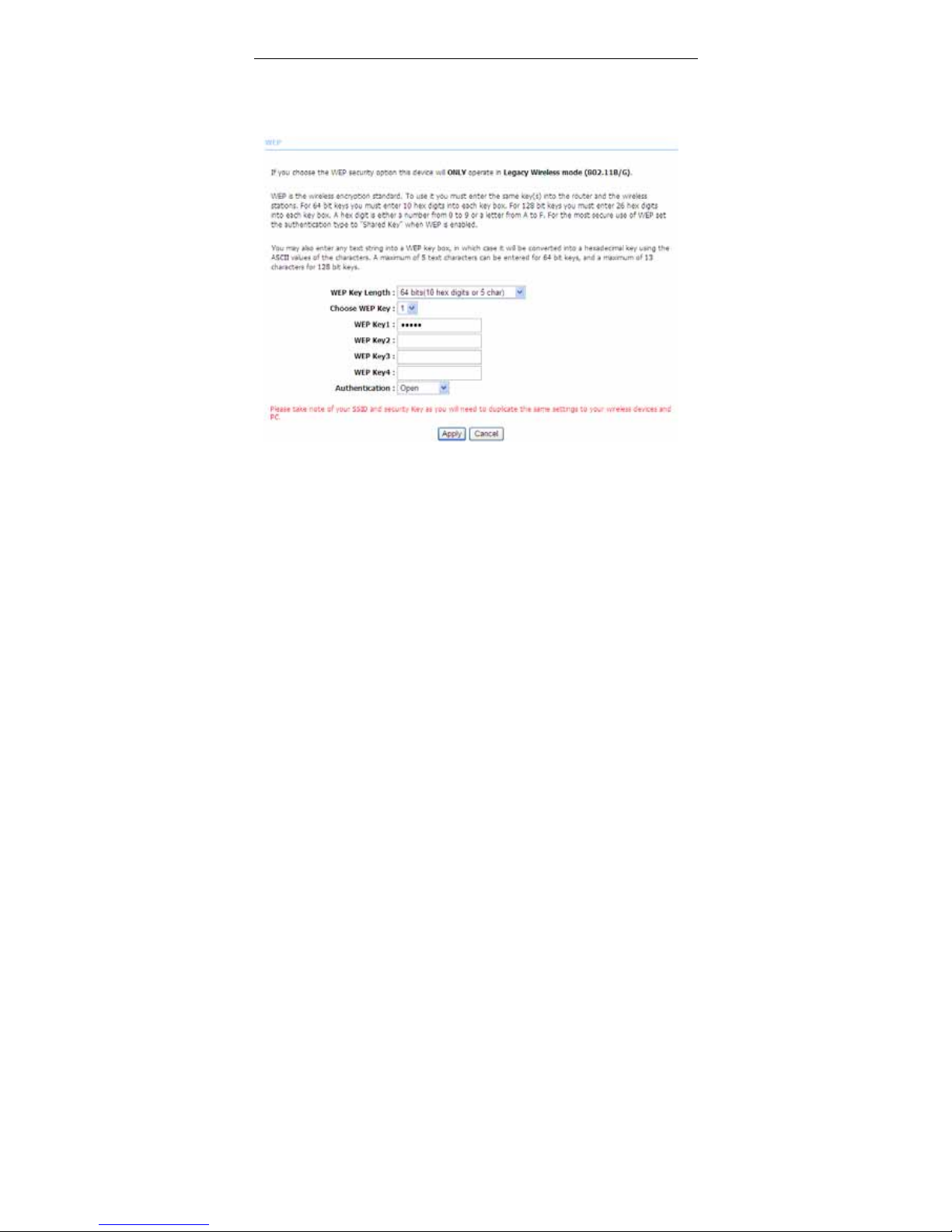
Field Description
WEP Key Length
Choose the WEP key length. You can Choose
64-bit or 128-bit.
Choose WEP Key
Choose the index of WEP Key. You can choose Key
1, 2, 3 or 4.
WEP Key 1/2/3/4
The Encryption keys are used to encrypt the data.
Both the modem and wireless stations must use the
same encryption key for data transmission. The
default key 1 is 8wlHK.
Click Apply to save the settings.
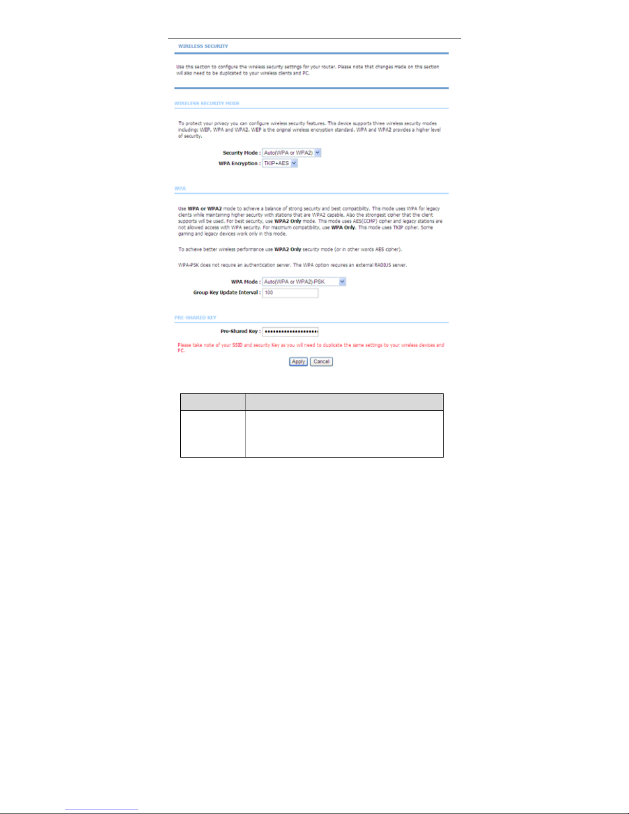
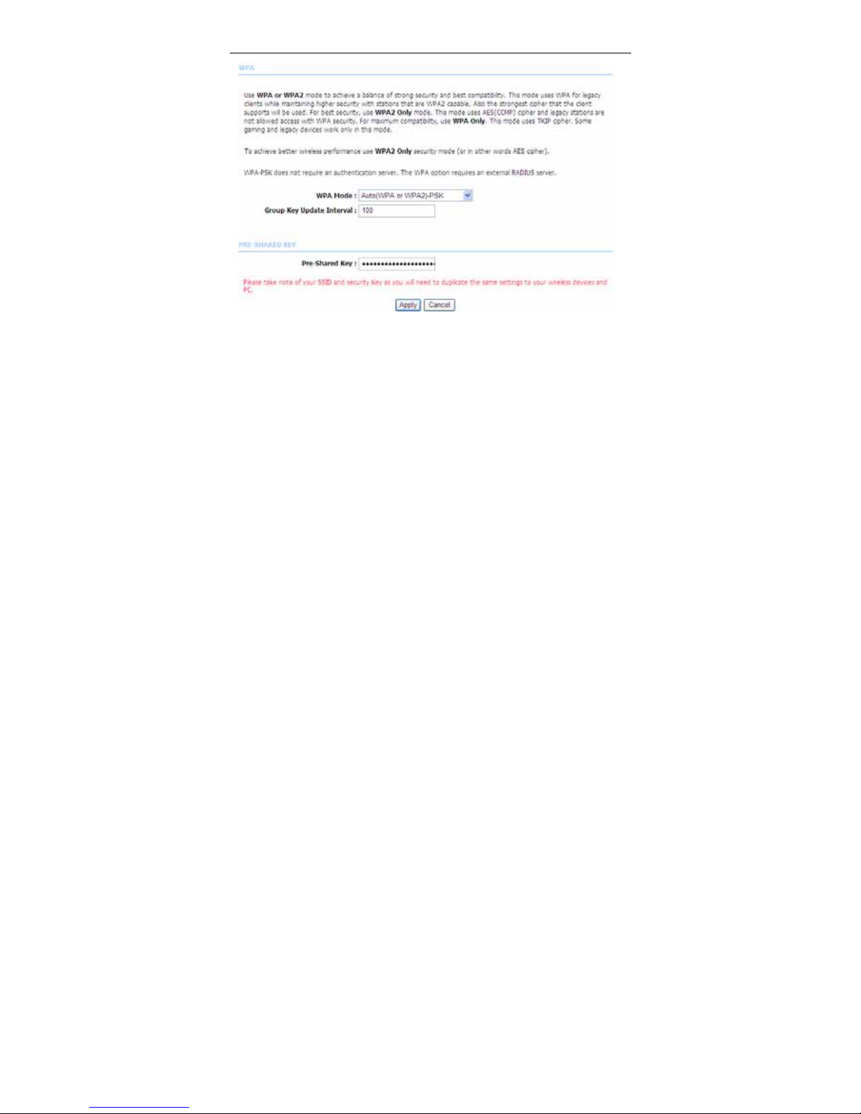
When the Security Mode is set as Auto (WPA or WPA2), WPA2 only or WPA
only, the following figure appears.
Page 30
User Manual
27
The following table describes the parameters in this page.
Field
Description
Security Mode
Configure the wireless encryption mode. You can
choose None, WEP, Auto(WPA or WPA2), WPA 2
Only or WPA Only.
Wired equivalent privacy (WEP) encrypts data
Page 31

User Manual
28
Field
Description
frames before transmitting over the wireless network.
Wi-Fi protected access (WPA) is a subset of the
IEEE802.11i security specification draft.
WPA2 Mixed is the collection of WPA and WPA2
encryption modes. The wireless client establishes the
connection between the modem through WPA or
WPA2.
Key differences between WPA and WEP are user
authentication and improved data encryption.
WPA
Encryption
When WPA or WPA2 is selected, you can select WPA
encryption as AES or TKIP+AES.
WPA Mode
Select PSK (Pre-Shared Key), enter the
pre-shared key in the Pre-Shared Key field.
Select Enterprise (RADIUS), enter the port, IP
address, and password of the Radius server. You need
to enter the username and password provided by the
Radius server when the wireless client connects the
modem.
If the encrypton is set to WEP, the modem uses 802.1
X authentication, which is Radius authentication.
Group Key
Update Interval
When WPA encryption is applied, messages sent are
encrypted with a password. For higher security, WPA
password is updated periodically. This value is the
update interval of the WPA password.
3.2.4 Local Network
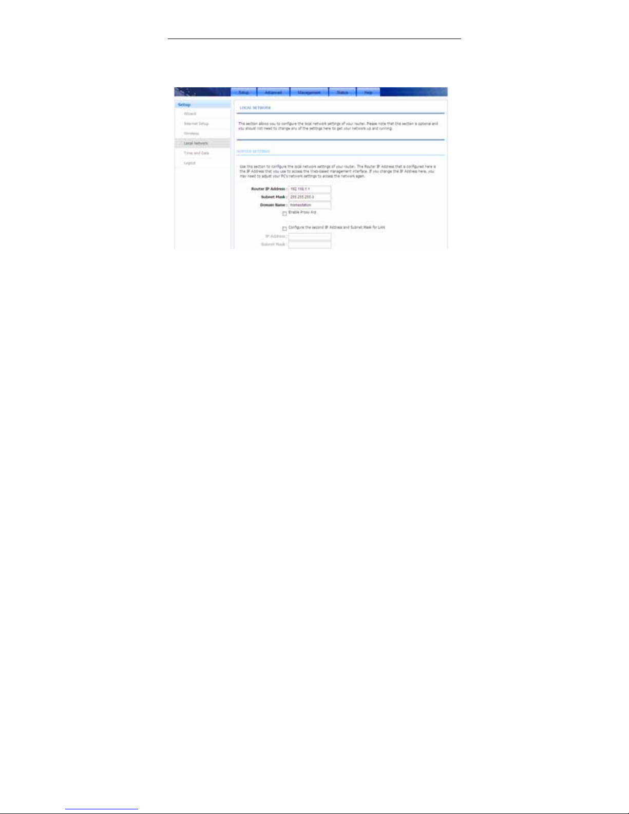
You can configure the LAN IP address according to the actual application. The
preset IP address is 192.168.1.1. You can use the default settings and DHCP
service to manage the IP settings for the private network. The IP address of the
device is the base address used for DHCP. To use the device for DHCP on your
LAN, the IP address pool used for DHCP must be compatible with the IP address
of the device. The IP address available in the DHCP IP address pool changes
automatically if you change the IP address of the device.
Page 32
User Manual
29
You can also enable the secondary LAN IP address. The two LAN IP addresses
must be in different networks.
Choose Setup > Local Network. The Local Network page shown in the
following figure appears.
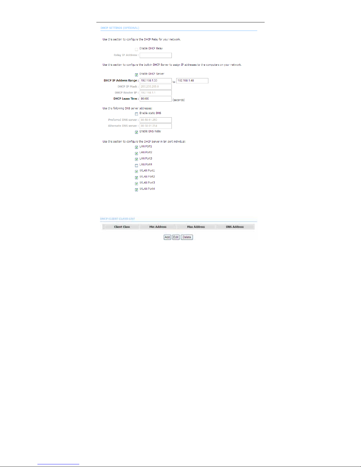
By default, Enable DHCP Server is selected for the Ethernet LAN interface of
the device. DHCP service supplys IP settings to workstations configured to
automatically obtain IP settings that are connected to the device through the
Ethernet port. When the device is used for DHCP, it becomes the default gateway
for DHCP client connected to it. If you change the IP address of the device, you
must also change the range of IP addresses in the pool used for DHCP on the
LAN. The IP address pool can contain up to 253 IP addresses.
Page 33
User Manual
30
Click Apply to save the settings.
The DHCP Client Class List section shown in the following figure appears.
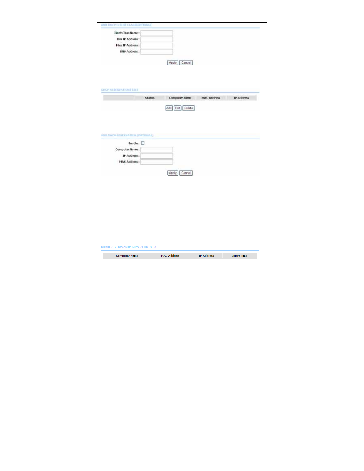
Click Add, the page shown in the following figure appears.
Page 34
User Manual
31
In the Local Network page, you can assign IP addresses on the LAN to specific
individual computers based on their MAC addresses.
Click Add to add static DHCP (optional). The page shown in the following figure
appears.
Select Enable to reserve the IP address for the designated PC with the
configured MAC address. The Computer Name helps you to recognize the PC
with the MAC address, for example, Father’s Laptop. Click Apply to save the
settings.
After the DHCP reservation is saved, the DHCP reservations list displays the
configuration.
The NUMBER OF DYNAMIC DHCP CLIENTS page shows the current DHCP
clients (PC or Laptop) connected to the device and the detailed information of the
connected computer(s).
Page 35
User Manual
32
3.2.5 Time and Date
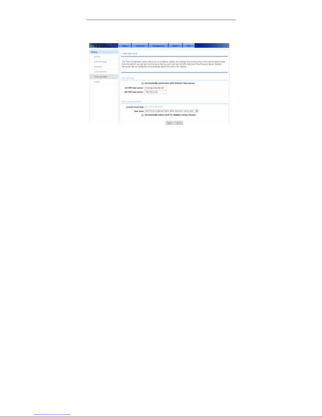
Choose Setup > Time and Date. The page shown in the following figure
appears.
In the Time and Date page, you can configure, update, and maintain the correct
time on the internal system clock. You can set the time zone that you are in and
the network time protocol (NTP) server. You can also configure daylight saving to
automatically adjust the time when needed.
Select Automatically synchronize with Internet time servers.
Select the specific time server and the time zone from the corresponding
drop-down lists.
Select Automatically adjust clock for daylight saving changes if necessary.
Set the daylight as you want.
Click Apply to save the settings.
3.2.6 Logout
Choose Setup > Logout. The page shown in the following figure appears. In this
page, you can log out of the configuration page.
Page 36

User Manual
33
3.3 Advanced
This section includes advanced features for network management, security and
administrative tools to manage the device. You can view status and other
information used to examine performance and troubleshoot.
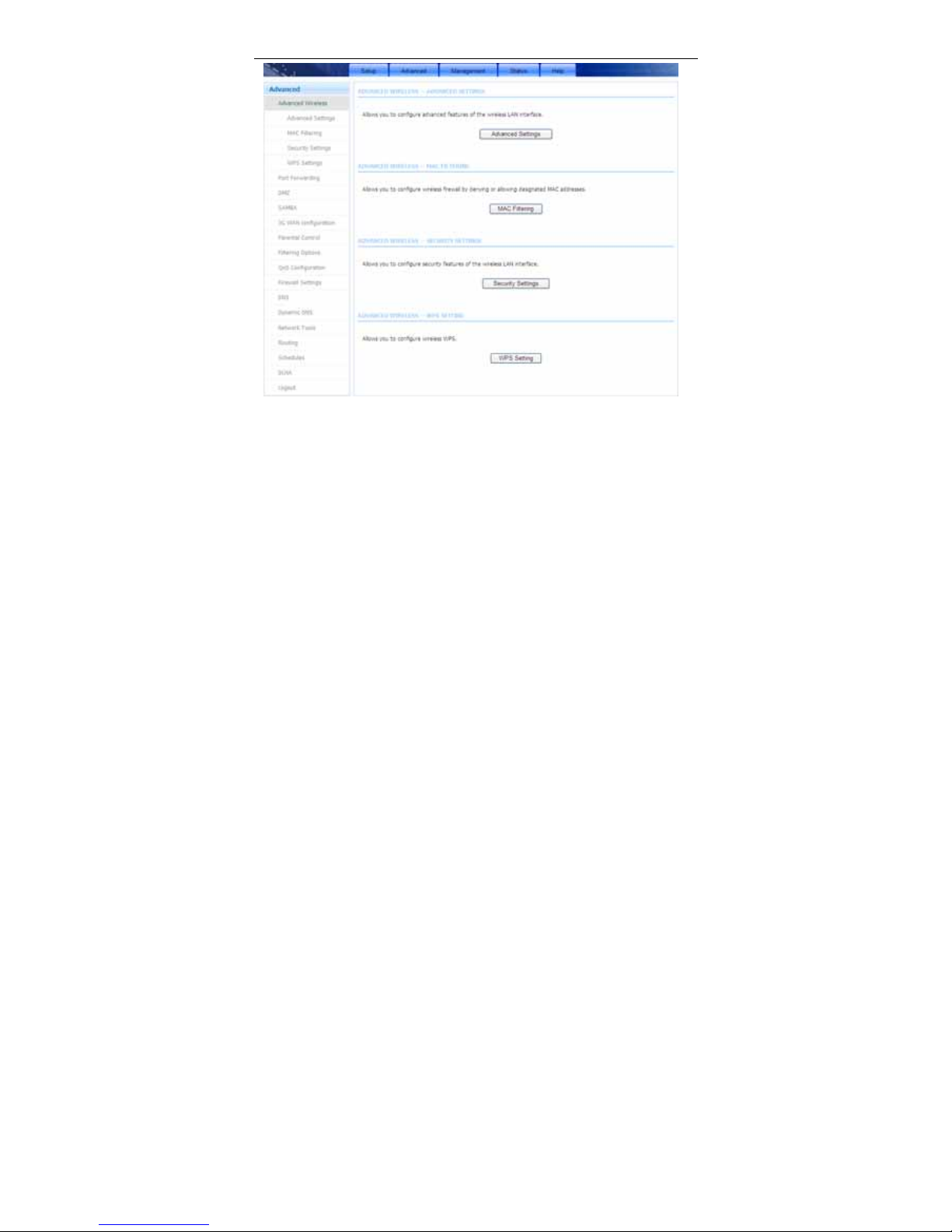
In the main interface, click Advanced tab to enter the Advanced menu as shown
in the following figure. The submenus are Advanced Wireless, Port Fowarding,
DMZ, SAMBA, 3G Configuration, Parental Control, Filtering Options, QoS
Configuration, Firewall Settings, DNS, Dynamic DNS, Network Tools,
Routing, Schedules, DLNA and Logout.
3.3.1 Advanced Wireless
This function is used to modify the standard 802.11g wireless radio settings. It is
suggested not to change the defaults, as incorrect settings may reduce the
performance of your wireless radio. The default settings provide the best wireless
radio performance in most environments.
Choose Advanced > Advanced Wireless. The page shown in the following
figure appears.
Page 37
User Manual
34
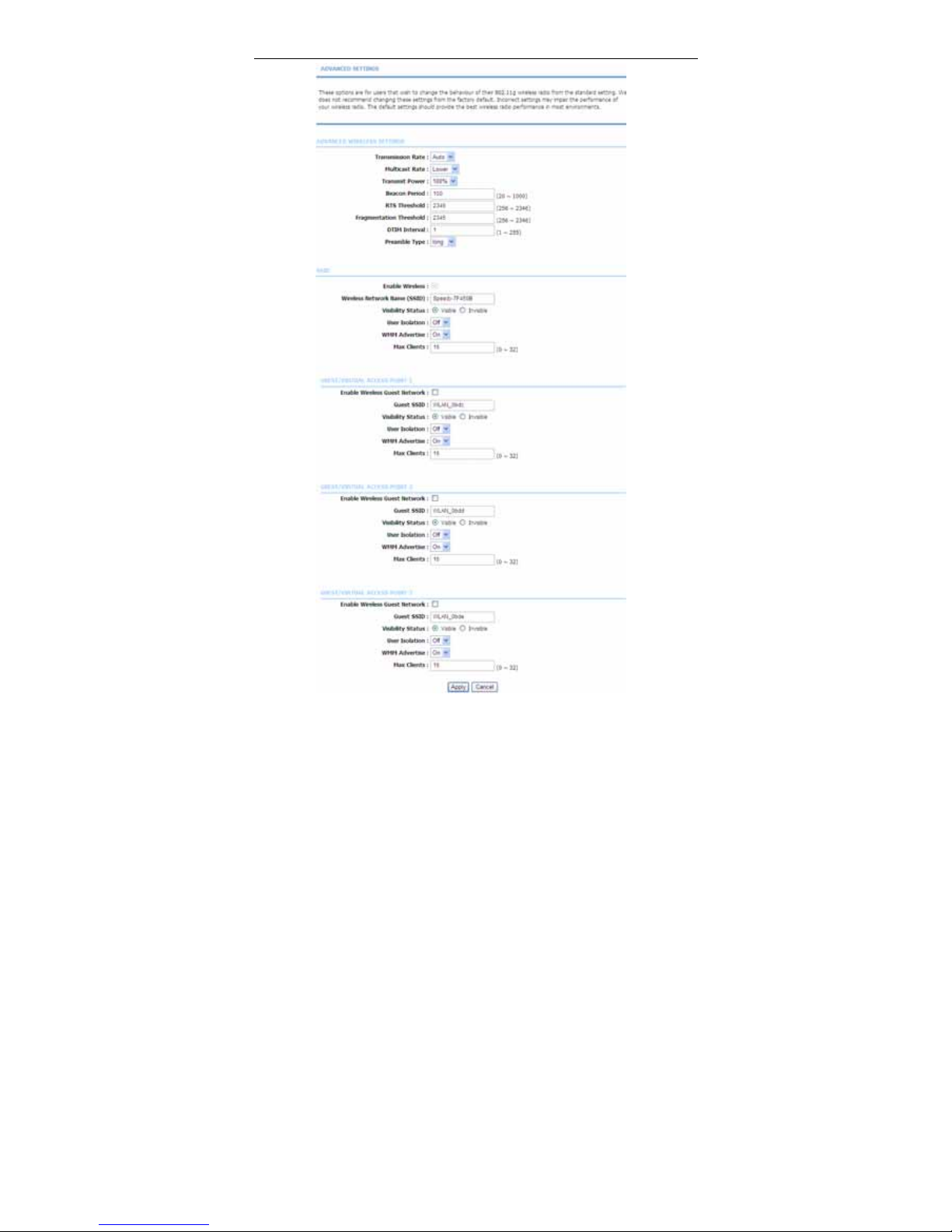
3.3.1.1 Advanced Settings
Select Advance Settings. The page shown in the following figure appears.
Page 38
User Manual
35
Page 39
User Manual
36
Wireless Network Name (SSID): The Wireless Network Name is a unique name
that identifies a network. All devices on a network must share the same wireless
network name in order to communicate on the network. If you decide to change
the wireless network name from the default setting, enter your new wireless
network name in this field.
These settings are only for more technically advanced users who have sufficient
knowledge about wireless LAN. Do not change these settings unless you know
the effect of changes on the device.
Click Apply to save the settings.
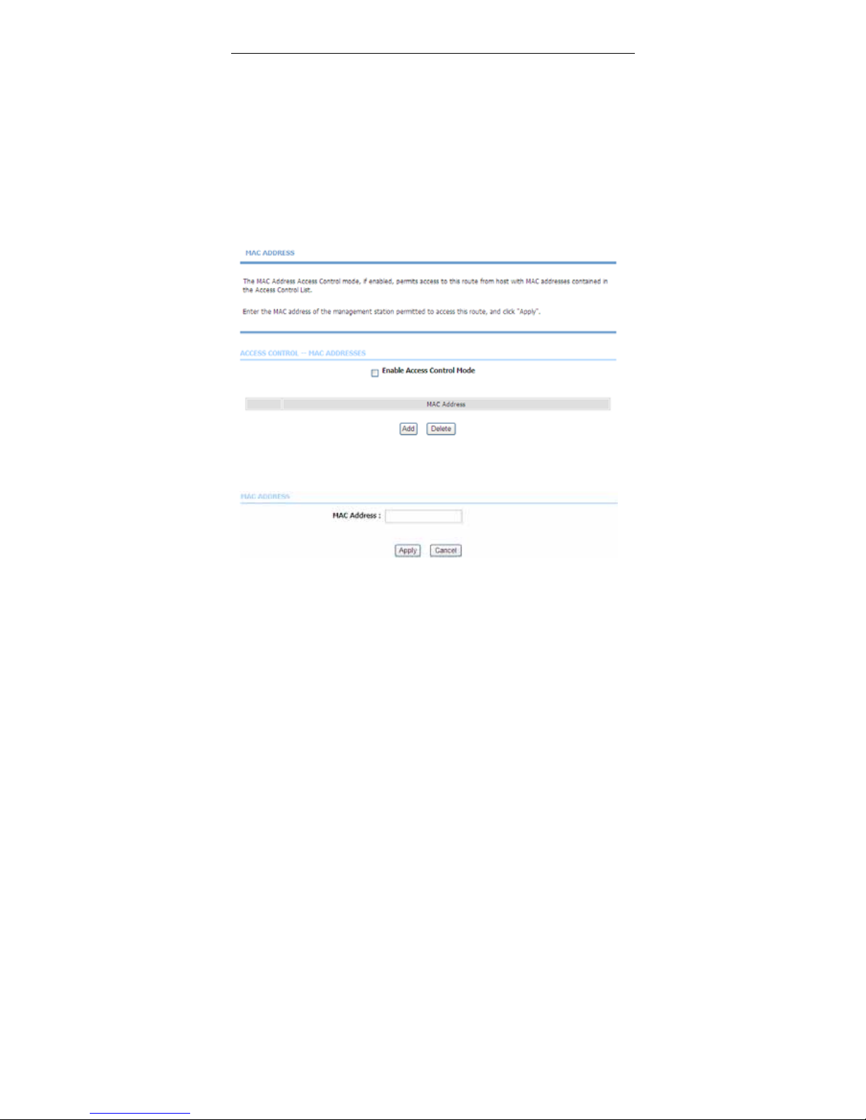
3.3.1.2 MAC Filtering
Select MAC Filtering. The page shown in the following figure appears.
Choose Enable Access Control Mode, and then click Add to add a MAC
Address as shown in the following figure.
Click Apply to finish.
Page 40
User Manual
37
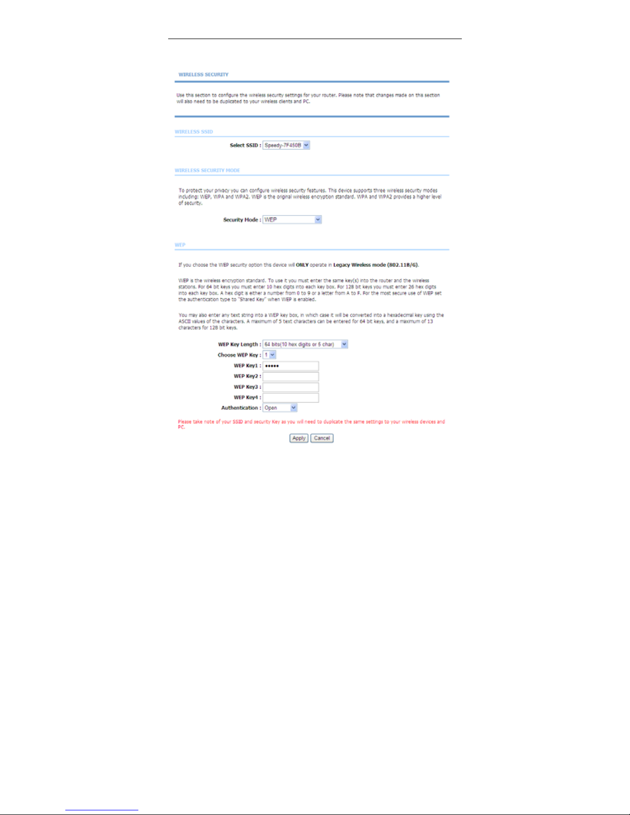
3.3.1.3 Security Settings
Select Security Settings. The page shown in the following figure appears.
Page 41
User Manual
38
Select the SSID that you want to configure from the drop-down list. Select the
encryption type from the Security Mode drop-down list.You can select None,
WEP, AUTO ( WPA or WPA2), WPA Only or WPA2 Only.
If you select WEP, the page shown in the following figure appears.
If you select AUTO (W PA or WPA2), WPA Only or WPA2 Only, the page shown
in the following figure appears.
Page 42
User Manual
39
Click Apply to save the settings. For detailed configuration, you may refer to
3.2.3.2 Wireless Security.
3.3.1.4 WPS Settings
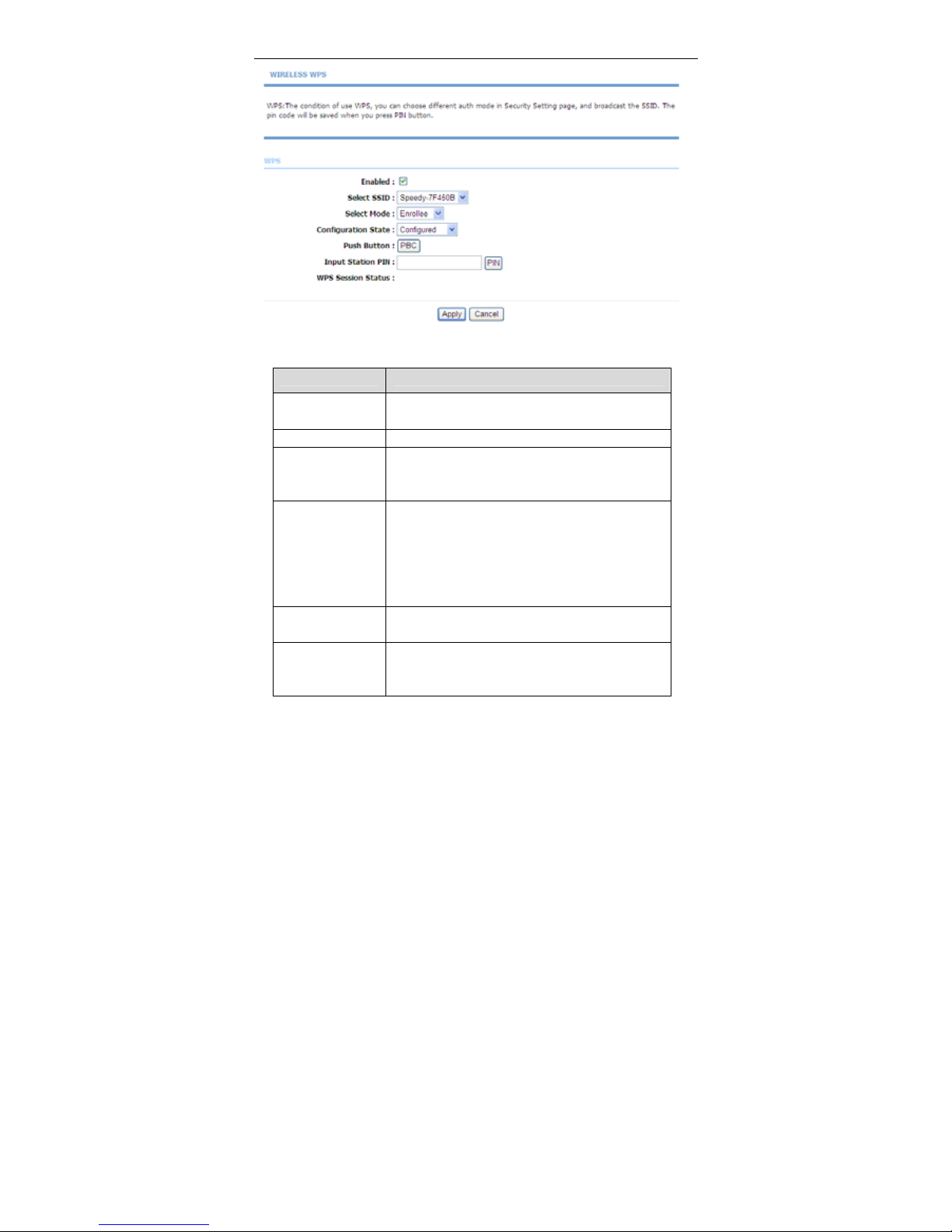
Select WPS Settings.This page is used to config WPS settings.
Page 43
User Manual
40
The following table describes the parameters of this page.
Field Description
Enabled
Choose to enable WPS function to set the following
parameters.
Select SSID Select one SSID of the CPE.
Select Mode
Select the mode either Registar or Enrollee. When
an AP or a station used Registar mode, the other
should use Enrollee mode.
Configuration
State
When Configured state is selected, wireless
parameters (for example, the encryption password)
are provided by the CPE in WPS negotiation. When
Unconfigured state is selected, wireless
parameters are provided by the connecting user end
(for example, PC).
Push Button
Press the button, the CPE will connect the station
automaticlly.
Input Station PIN
You need to enter a pin the station which mode is
Enrollee Generate. Press the button to connect the
other with the pin.
Page 44
User Manual
41
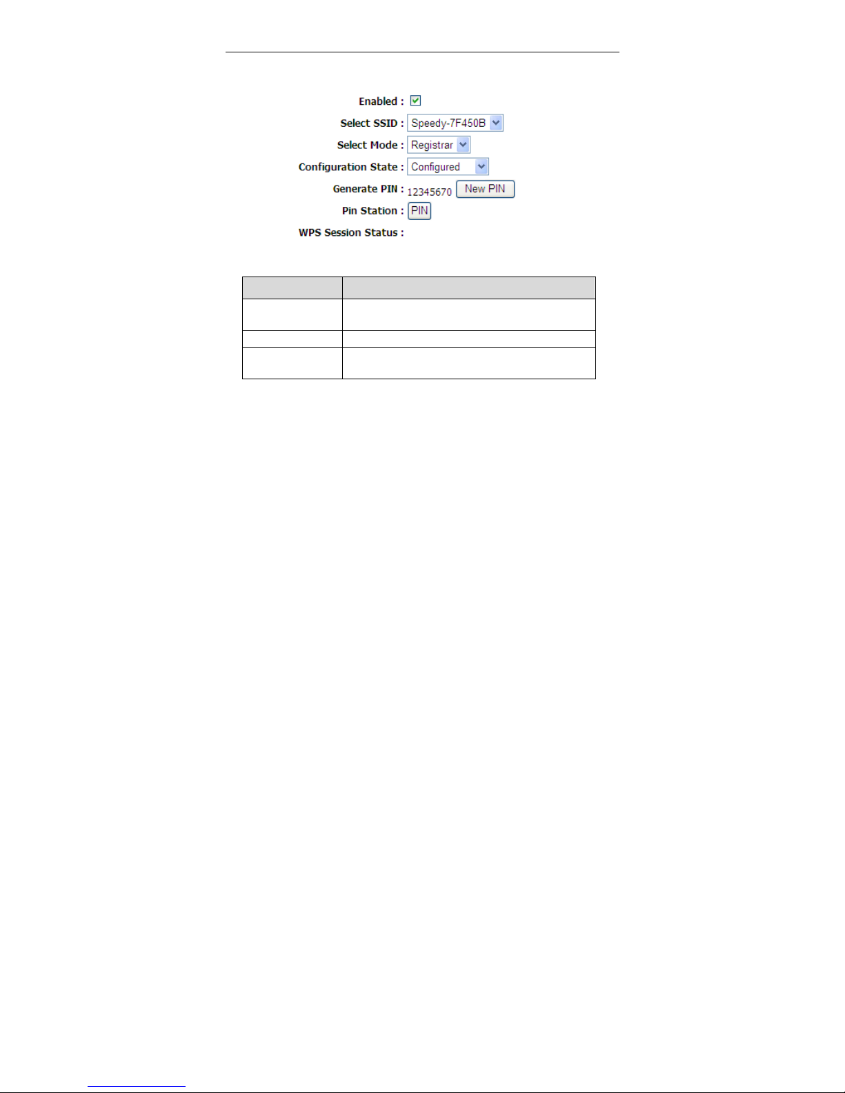
When Registrar mode is chosen, the following figure appears. In this condition,
only PIN button can be used.
The following table describes the parameters of this page.
Field Description
Generate PIN
Press the button to generate a pin used by the AP
and the station.
PIN Station Press the button to connect the station with the pin.
WPS Session
Status
Display the session status.
3.3.2 Port Forwarding
This function is used to open ports in your device and re-direct data through
those ports to a single PC on your network (WAN-to-LAN traffic). It allows remote
users to access services on your LAN, such as FTP for file transfers or SMTP
and POP3 for e-mail. The device accepts remote requests for these services at
your global IP address. It uses the specified TCP or UDP protocol and port
number, and redirects these requests to the server on your LAN with the LAN IP
address you specify. Note that the specified private IP address must be w ithin the
available range of the subnet where the device is in.
Choose Advanced > Port Forwarding. The page shown in the following figure
appears.
Page 45

User Manual
42
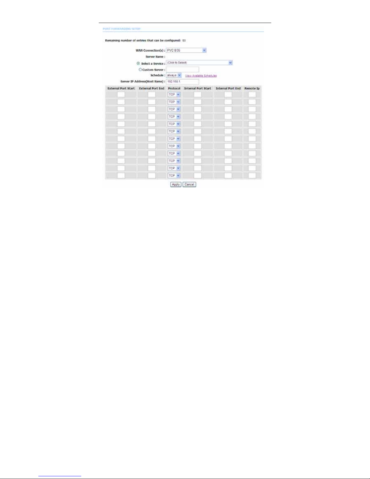
Click Add to add a virtual server.
Page 46
User Manual
43
Select a service for a preset application, or enter a name in the Custom Server
field.
Enter an IP address in the Server IP Address field to appoint the corresponding
PC to receive forwarded packets.
The Ports show the ports that you want to open on the device. The TCP/UDP
means the protocol type of the opened ports.
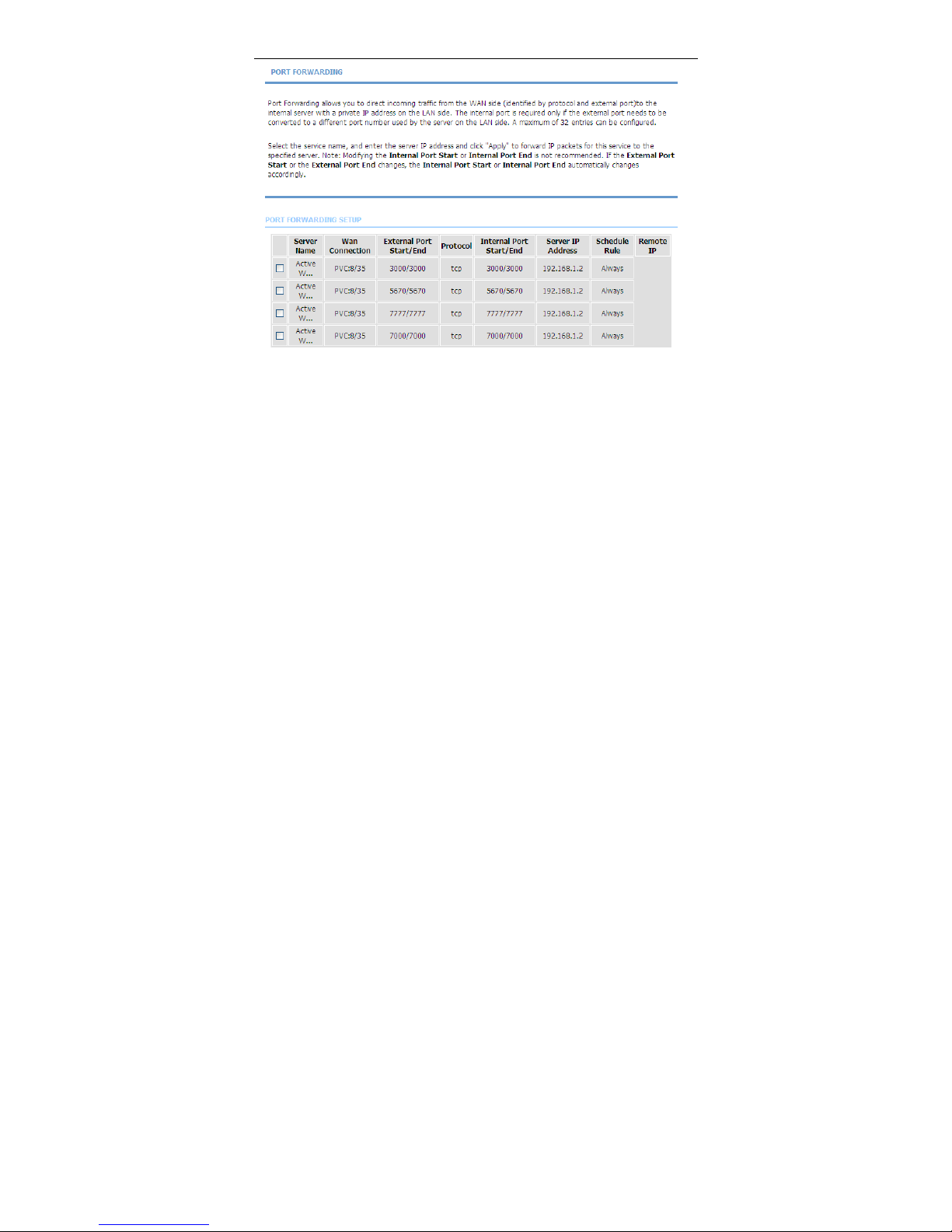
Click Apply to save the settings. The page shown in the following figure appears.
A virtual server is added.
Page 47
User Manual
44
3.3.3 DMZ
Since some applications are not compatible with NAT, the device supports the
use of a DMZ IP address for a single host on the LAN. This IP address is not
protected by NAT and it is visible to agent s on the Internet with the correct type of
software. Note that any client PC in the DMZ is exposed to various types of
security risks. If you use the DMZ, take measures (such as client-based virus
protection) to protect the remaining client PCs on your LAN from possible
contamination through DMZ.
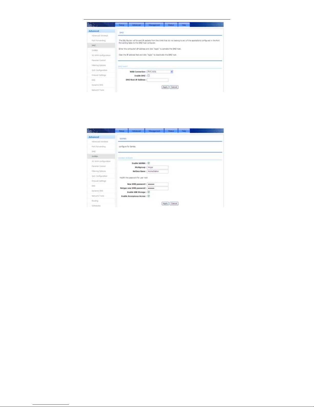
Choose Advanced > DMZ. The page shown in the following figure appears.
Page 48
User Manual
45
Click Apply to save the settings.
3.3.4 SAMBA
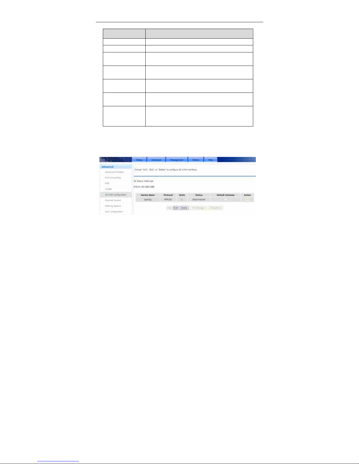
Select Advanced > SAMBA.The page shown in the following figure appears.
Page 49
User Manual
46
The following table describes the parameters of this page.
Field Description
Enable SAMBA Select the check box to enable the samba service
Workgroup Enter the name of your local area network (LAN).
Netbios Name
Enter your netbios name which is an identifier used
by netbios services running on a computer.
New SMB
password
Enter your samba password for user root.
Retype new SMB
password
Reconfirm your samba password here.
Enable USB
Storage
Select the check box to support USB storage.
Enable
Anonymous
Access
Select the check box to allow anonymous users
access.
3.3.5 3G WAN Configuration
Choose Advanced > 3G WAN Configuration. The page shown in the following
figure appears.
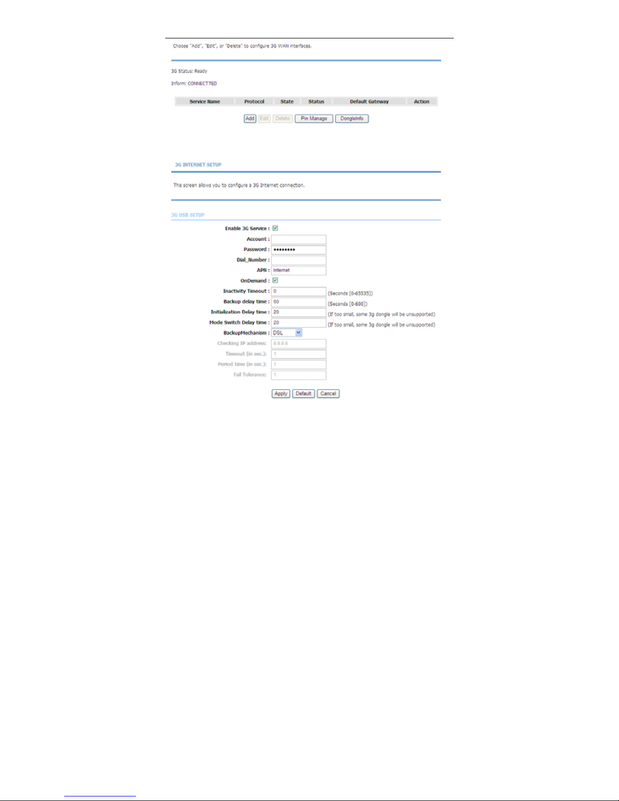
If you want to access the Internet through 3G connection, a 3G USB data card is
required. Connect the 3G data card to the USB interface of the Router and the
following will appear.
Page 50
User Manual
47
Click Add to display the following figure. In this page, you can configure 3G
Internet connection.
Page 51

User Manual
48
The following table describes the parameters of this page.
Field Description
Enable 3G Service You may choose to enable or disable 3G service.
Account Enter the account.
Password
Enter the password.
Dial_Number
Enter the dial number.
APN
Enter the access point.
OnDemand
You may choose to dial on demand.
Inactivity Timeout
Set the period without flow before disconnecting
3G connection. When 0 is set, 3G connection will
always be connected regardless of flow.
Backup delay time
Set the period before starting 3G dial after ADSL
disconnection.
Initialization Delay
time
Set the initialization time of 3G USB data card.
Mode Switch Delay
time
Set the time for the 3G USB data card to switch
from a storage device to a communication
device.
Backup Mechanism
When DSL is selected, 3G dial starts after DSL
disconnection. Usually DSL is selected.
When IPCHECK is selected, 3G dial starts when
DSL connection is established and the address
set in Checking IP address can not be pinged.
Checking IP address
It is an address for 3G detection. After DSL
dialup, if this address cannot be pinged, 3G dial
will be started.
Timeout (in sec.)
Set the ping timeout.
Period time (in sec.)
Set the interval between two times of ping.
Fail Tolerance
Set the allowed times of ping failure.
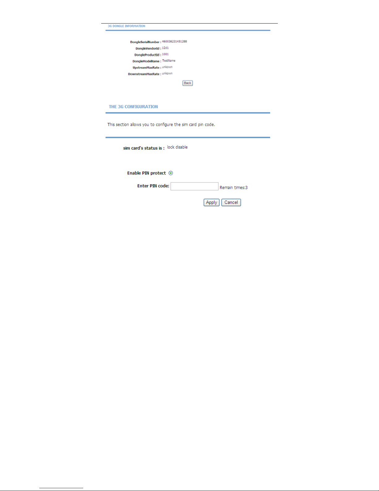
You may click DongleInfo to view 3G network card information as shown in the
following figure.
Page 52
User Manual
49
Click Pin Manage to enable the 3G PIN code as shown in the following figure.
Enter the applied PIN code in the Enter PIN code field, and then click Apply to
finish.
Page 53
User Manual
50
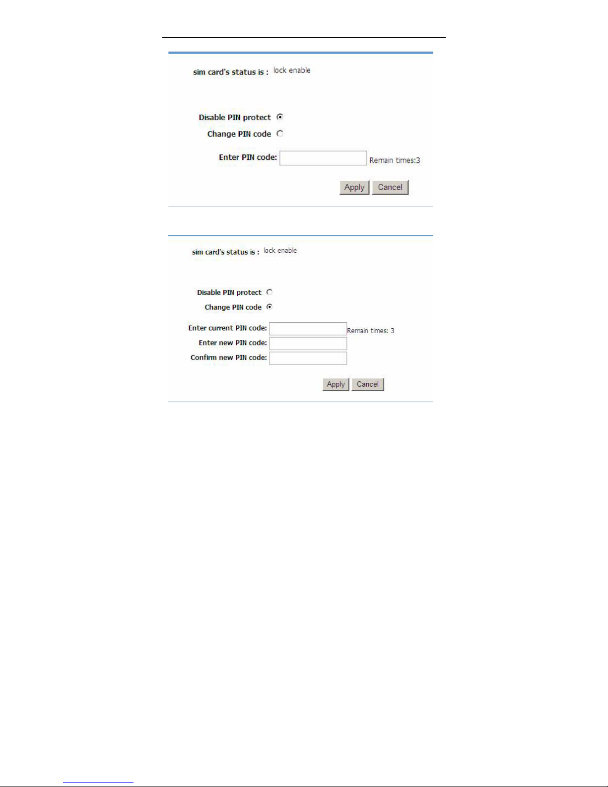
You can disable the 3G PIN code as shown in the following figure.
Select Disable PIN protect, and then click Apply to finish.
You can Change the PIN code as shown in the following figure.
Enter current PIN code and a new one for twice, and then click Apply to finish.
Page 54
User Manual
51
Note:
If a wrong PIN code is input continuously for three times, the PUK
code will be required to unlock the PIN code.
3.3.6 Parental Control
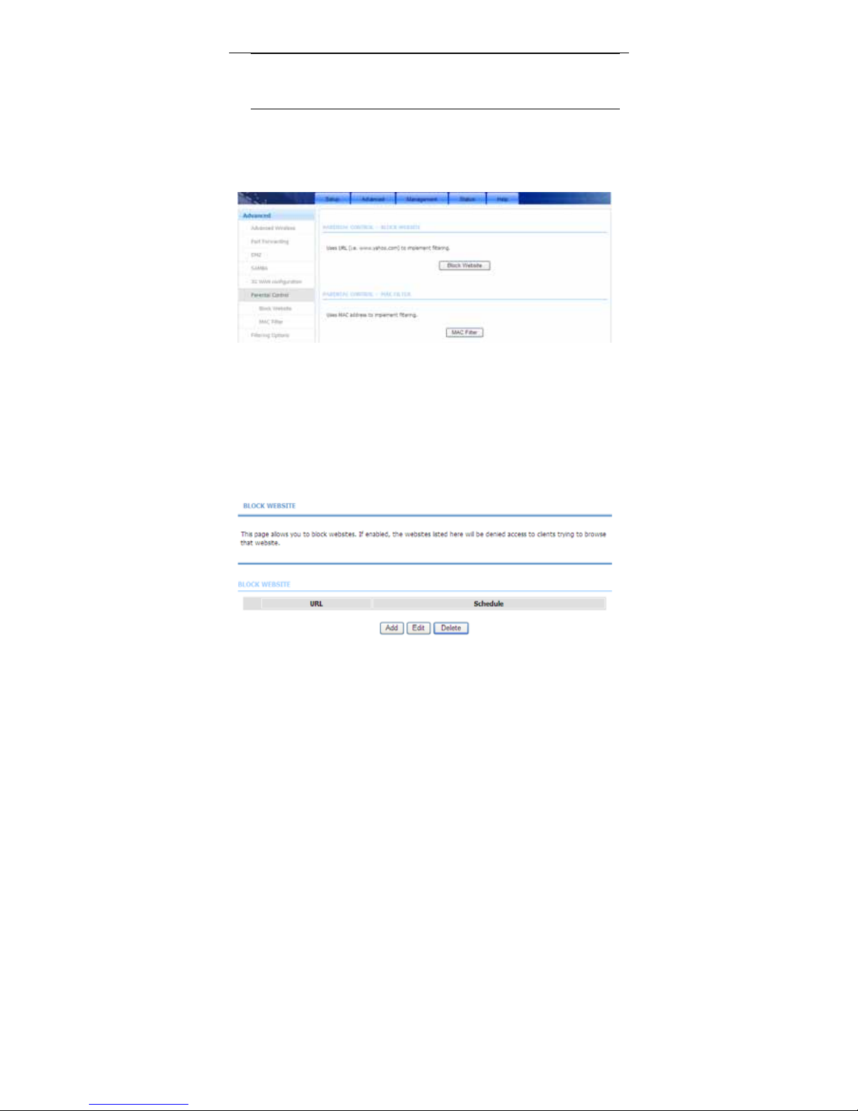
Choose Advanced > Parental Control. The Parent Control page shown in the
following figure appears.
This page provides two useful tools for restricting the Internet access. Block
Websites allows you to quickly create a list of all websites that you wish to stop
users from accessing. Block MAC Address allows you to control when clients or
PCs connected to the device are allowed to access the Internet.
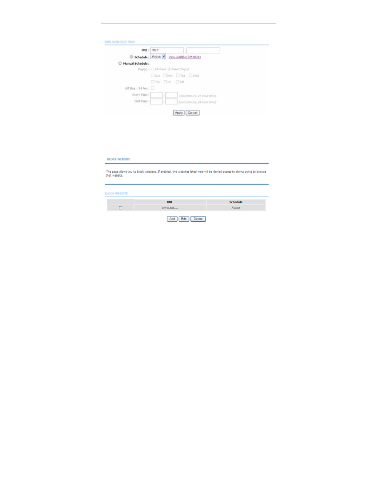
3.3.6.1 Block Website
In the Parent Control page, click Block Website. The page shown in the
following figure appears.
Page 55
User Manual
52
Click Add. The page shown in the following figure appears.
Enter the website in the URL field. Select the Schedule from the drop-down list,
or select Manual Schedule and select the corresponding time and days.
Click Apply to add the website to the BLOCK WEBSITE table. The page shown
in the following figure appears.
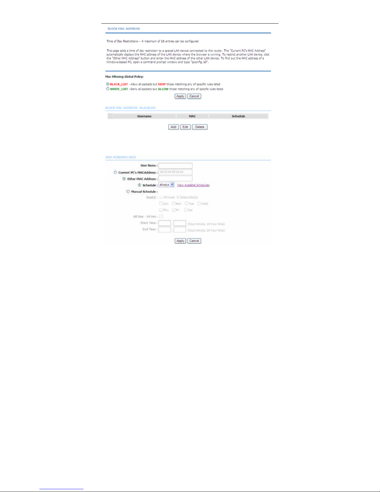
3.3.6.2 Block MAC Filter
In the Parent Control page, click Block MAC Address. The page shown in the
following figure appears.
Page 56
User Manual
53
Choose BLACK_LIST or WHITE_LIST, and then click Add. The page shown in
the following figure appears.
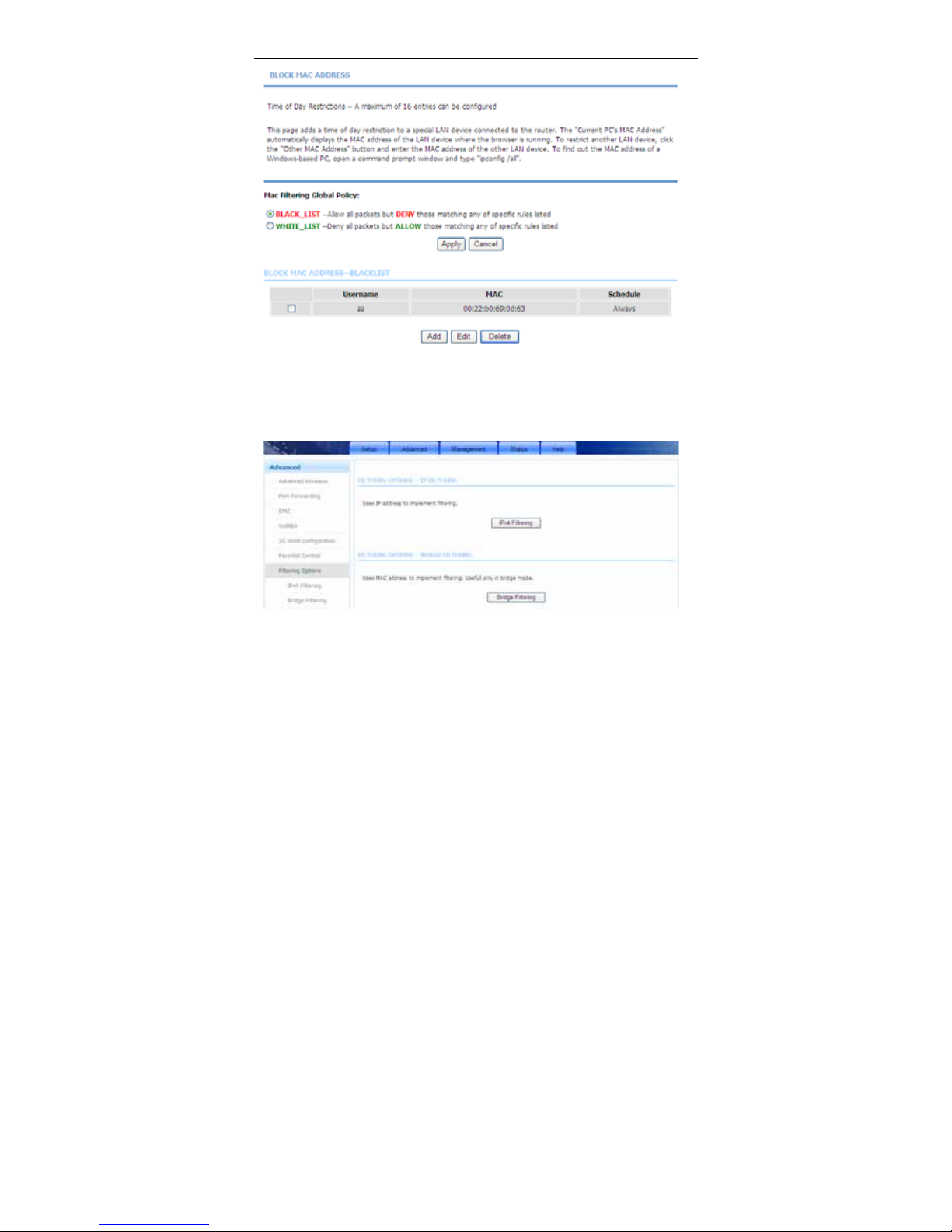
Enter the use name and MAC address and select the corresponding time and
days. Click Apply to add the MAC address to the BLOCK MAC ADDRESS
Table. The page shown in the following figure appears.
Page 57
User Manual
54
3.3.7 Filtering Options
Choose Advanced > Filteri ng Options. The Filtering Options page shown in
the following figure appears.
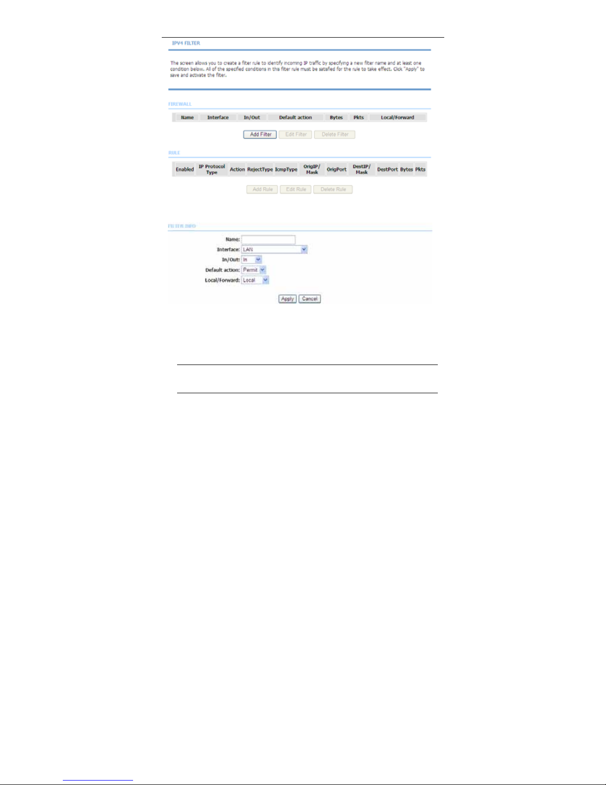
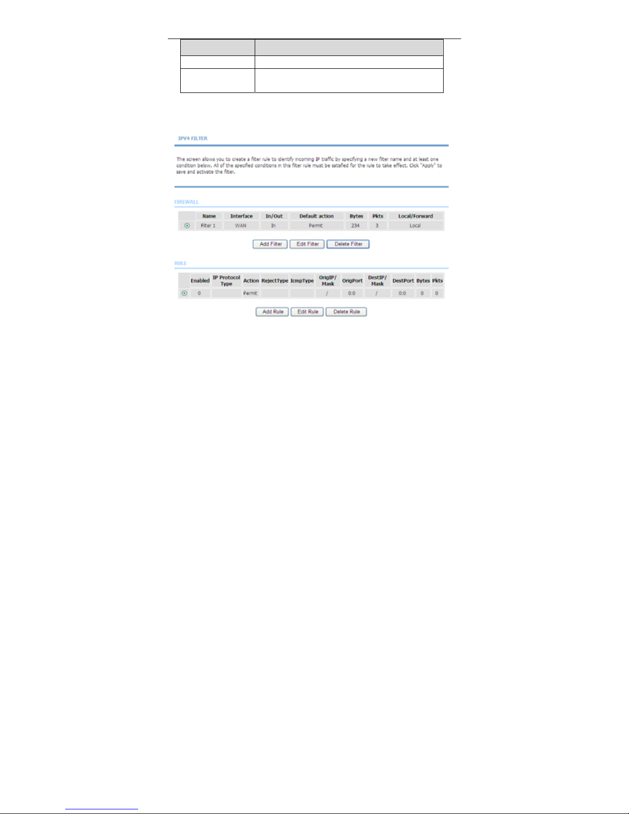
3.3.7.1 IPv4 Filtering
In the Filtering Options page, click IPv4 Filtering. The page shown in the
following figure appears. In this page, you may configure IPv4 firewall function.
Page 58
User Manual
55
Click Add Filter. The page shown in the following figure appears.
Enter the Filter Name and specify at least one of the following criteria: Interface,
In/Out, Default action and Local/Forward.
Click Apply to save the settings.
Note:
The settings are applicable only when the firewall is enabled.
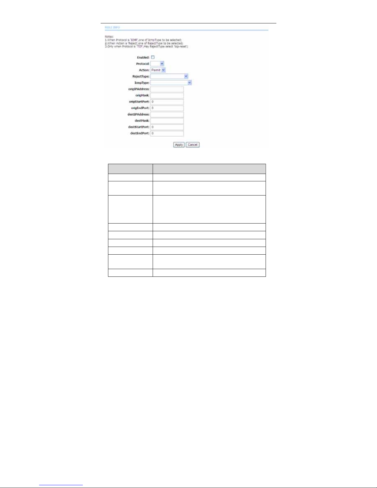
Click Add Rule. The page shown in the following figure appears.
Page 59
User Manual
56
The following table describes the parameters of this page.
Field Description
Enable Tick in the box to enable a firewall rule.
Protocol
Choose a protocol corresponding to the rule. You
may choose TCP, UDP or ICMP.
Action
The action when the rule is matched. Permit means
allowing the message to pass, Drop means
discarding messages without a reply, and Reject
means discarding messages with a reply.
Reject Type
The type of message sent in a Reject action.
Icmp Type
Type of ICMP messages
origIPAddress
Original IP address
origMask
Original address mask
origStart/End Port
Original start/ end port, which is the original port
range
destIPAddress
Destination address
Page 60
User Manual
57
Field Description
destMask
Destination address mask
dest Start/End
Port
Destination start/ end port, which is the original port
range
After setting the parameters, click Apply. The page shown in the following figure
appears.
3.3.7.2 Bridge Filtering
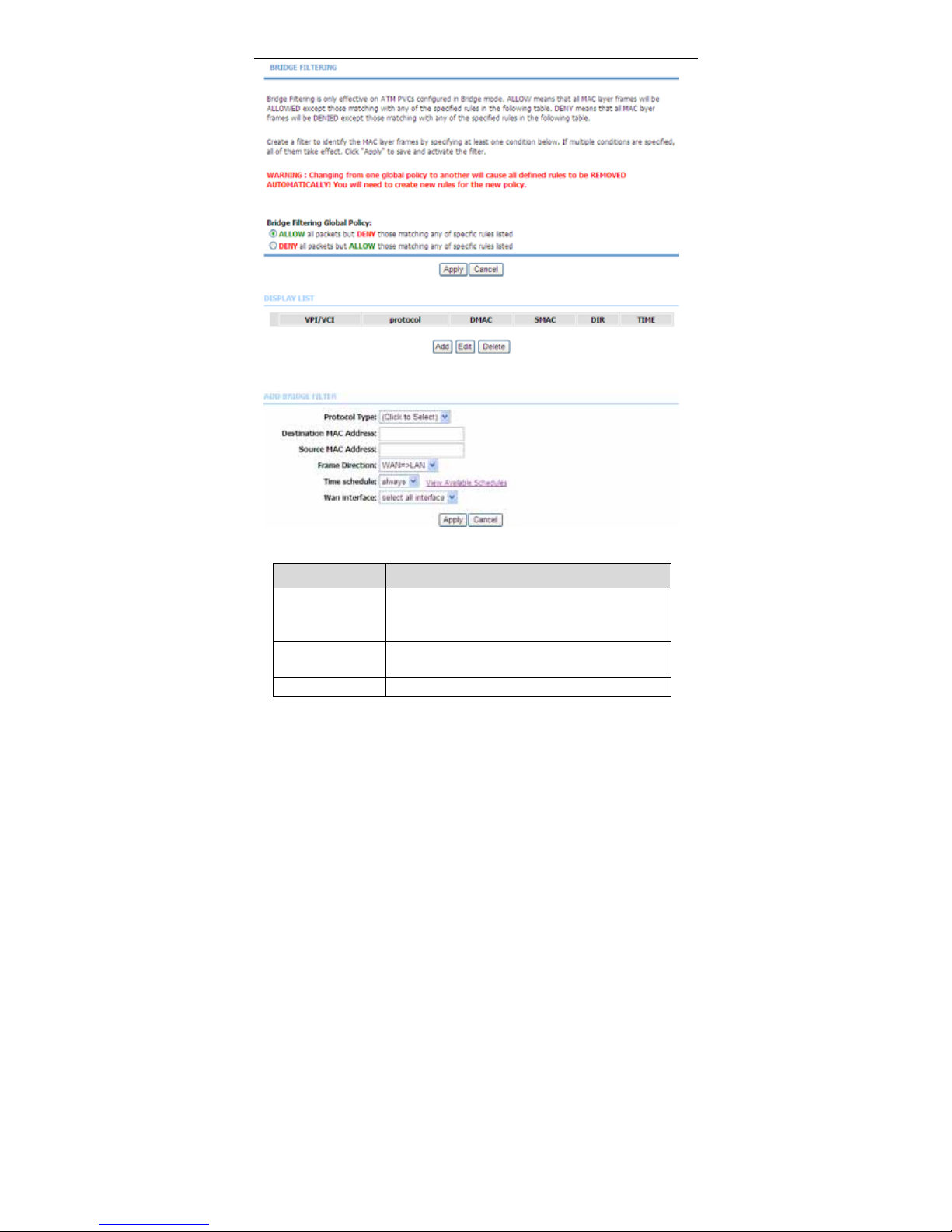
In the Filtering Options page, click Bridge Filtering. The page shown in the
following figure appears.This page is used to configure bridge parameters. In this
page, you can change the settings or view some information of the bridge and its
attached ports.
Page 61
User Manual
58
Click Add to add a bridge filter. The page shown in the following figure appears.
The following table describes the parameters of this page.
Field Description
Protocol Type
Choose a third-layer protocol type for bridge filtering
from the drop-down list. You may choose PPPoE,
IPv4, IPv6, AppleTalk, IPX, NetBEUI or IGMP.
Destination MAC
Address
The MAC address of sendee of the message
Source MAC
The MAC address of sender of the message
Page 62
User Manual
59
Field Description
Address
Frame Direction
Choose the sending direction as WAN to LAN or
LAN to WAN.
Time schedule
Choose the filtering strategy as always or never.
Wan interface
Set an effective interface for the bridge filtering rule.
Click Apply to save the settings.
3.3.8 QoS Configuration
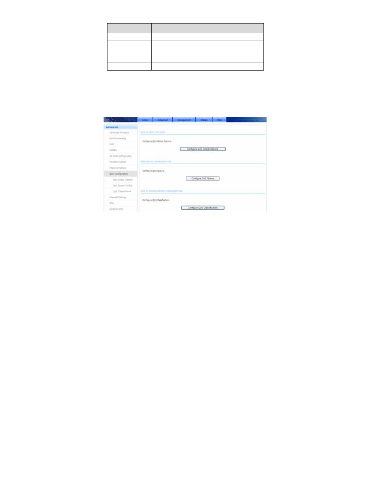
Choose Advanced > QoS Configuration. The QoS Configuration page shown
in the following figure appears.
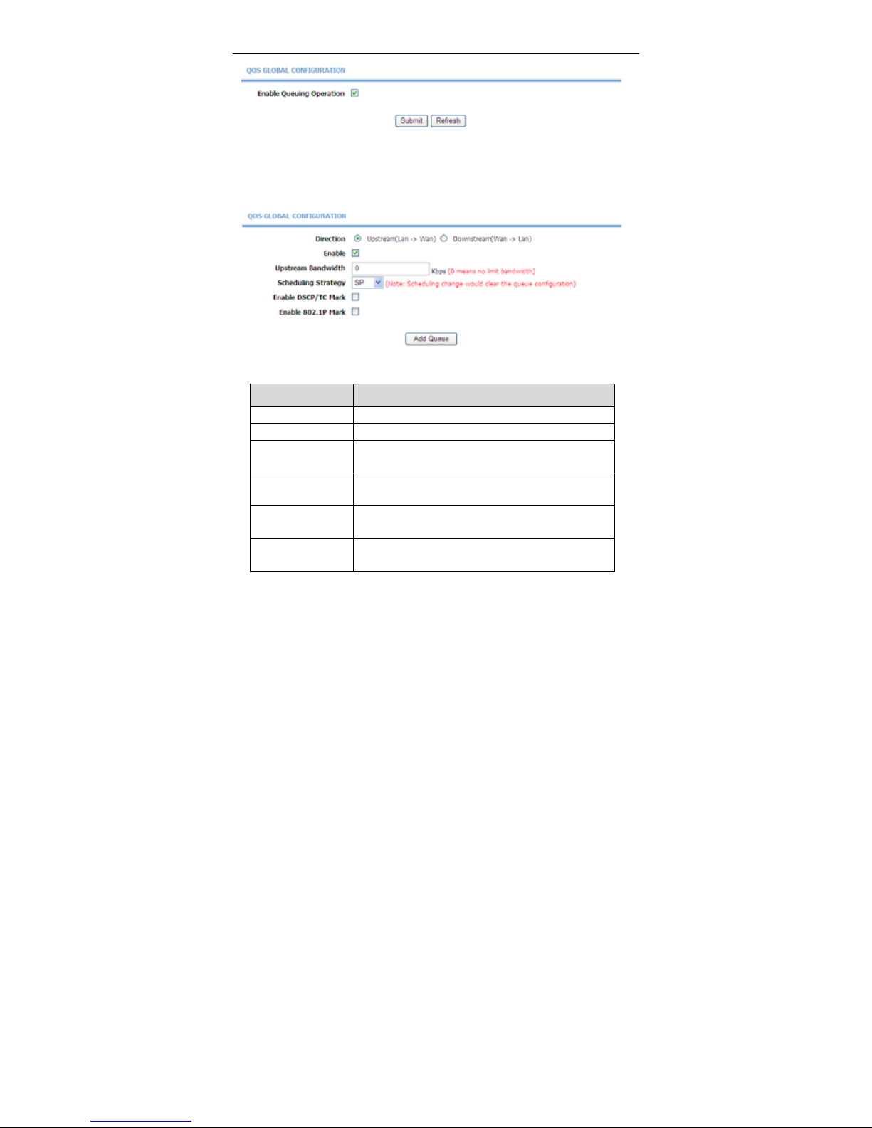
3.3.8.1 QoS Global Options
In the QoS Configuration page, click QoS Global Options. The page shown in
the following figure appears.You can tick in the checkbox and then click Submit
to enable queuing operation.
Page 63
User Manual
60
3.3.8.2 QoS Queue Config
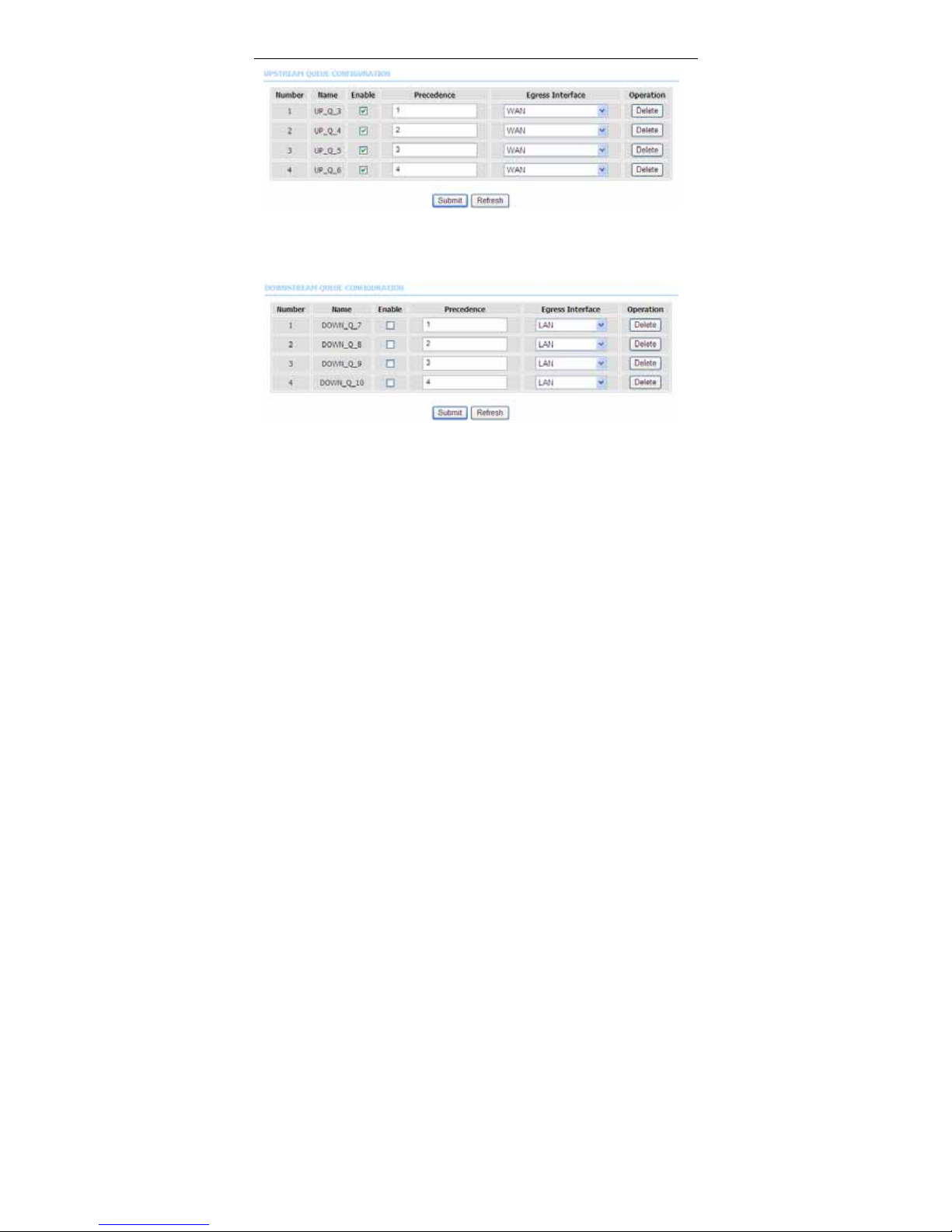
In the QoS Configuration page, click QoS Queue Config. The page shown in
the following figure appears. In this page, you can set QoS flow control.
The following table describes the parameters of this page.
Field Description
Direction Choose Upstream queue or Downstream queue.
Enable Tick in the box to enable queue.
Upstream
Bandwidth
Total bandwith for upstream flow
Scheduling
Strategy
Scheduling algorithm of QoS queue
Enable DSCP/TC
Mark
You may tick in the box to permit DSCP/TC Mark.
Enable 802.1P
Mark
You may tick in the box to permit 802.1P Mark.
After setting the parameters, click Add Queue to add a queue.
In the above page, when Upstream (Lan -> Wan) direction is chosen, you need
to configure the parameters in the following figure.
Page 64
User Manual
61
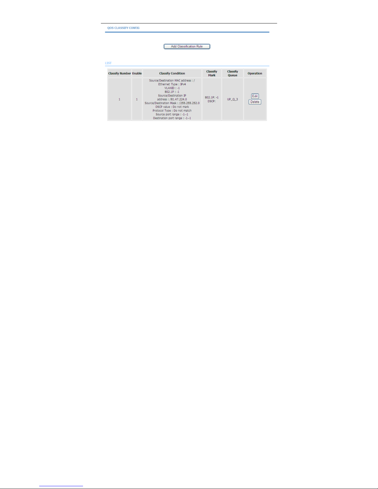
When Downstream (Lan -> Wan) direction is chosen, you need to configure the
parameters in the following figure.
After modifying a queue, click Submit to enable the modification. Click Refresh
to refresh the queue.
3.3.8.3 QoS Classification
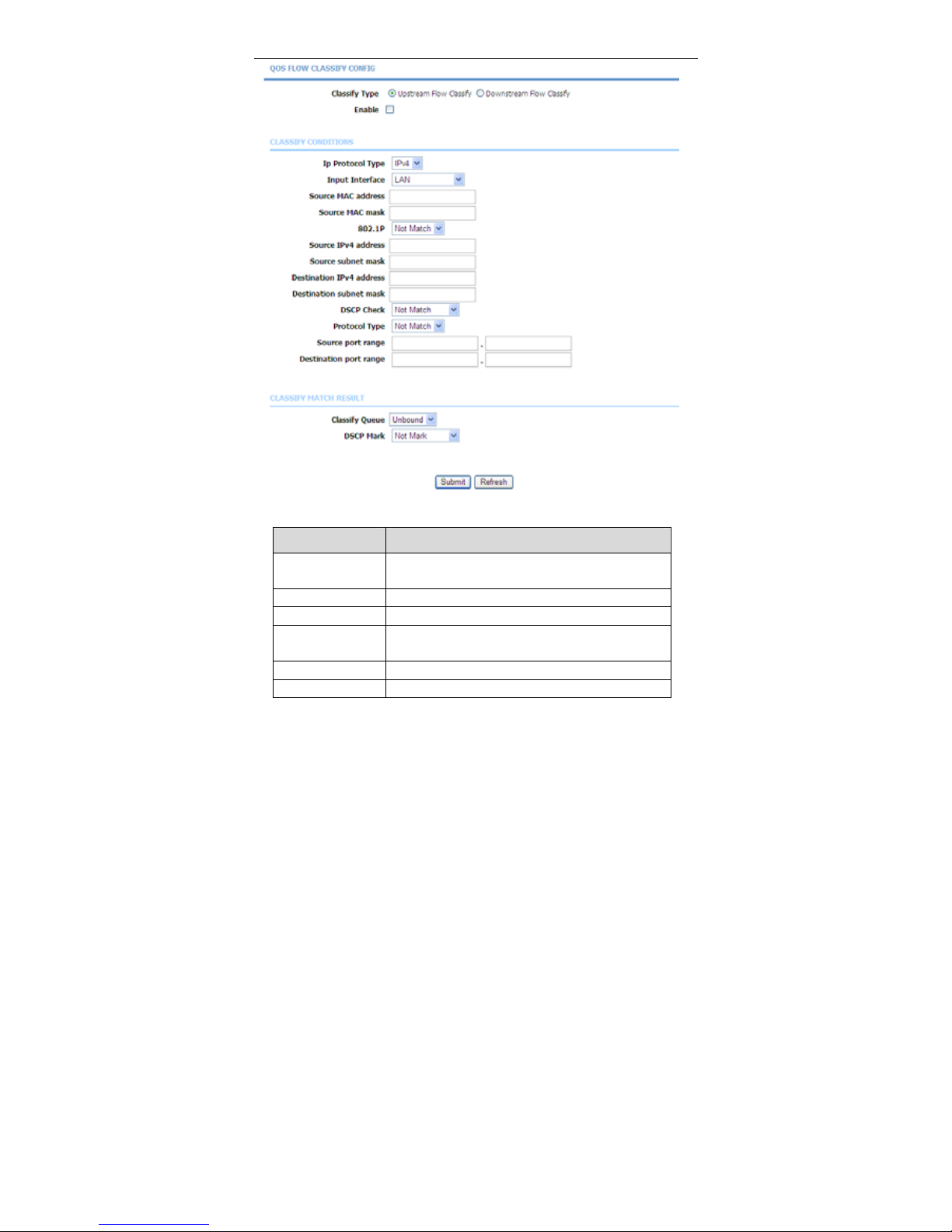
In the QoS Configuration page, click QoS Classification. The page shown in
the following figure appears.You can configure QoS queue rule.
Page 65
User Manual
62
Click Add Classification Rule. The page shown in the following figure appears.
Page 66
User Manual
63
The following table describes the parameters of this page.
Field Description
Classify Type
Set the QoS rule type as Upstream or
Downstream.
Enable Tick in the box to enable this QoS rule.
Ip Protocol Type Select the protocol type IPv4.
Input Interface
Based on the Classify Type, choose a WAN/LAN
interface.
802.1P Choose a matched 802.1P VLAN priority.
DSCP Check Choose a matched DSCP type.
Page 67
User Manual
64
Field Description
Protocol Type Choose a protocol type matching with the QoS rule.
Classify Queue Choose a QoS queue for the rule.
DSCP Mark Set a DSCP Mark for this QoS rule.
You may click Edit to modify the existing classification rule.
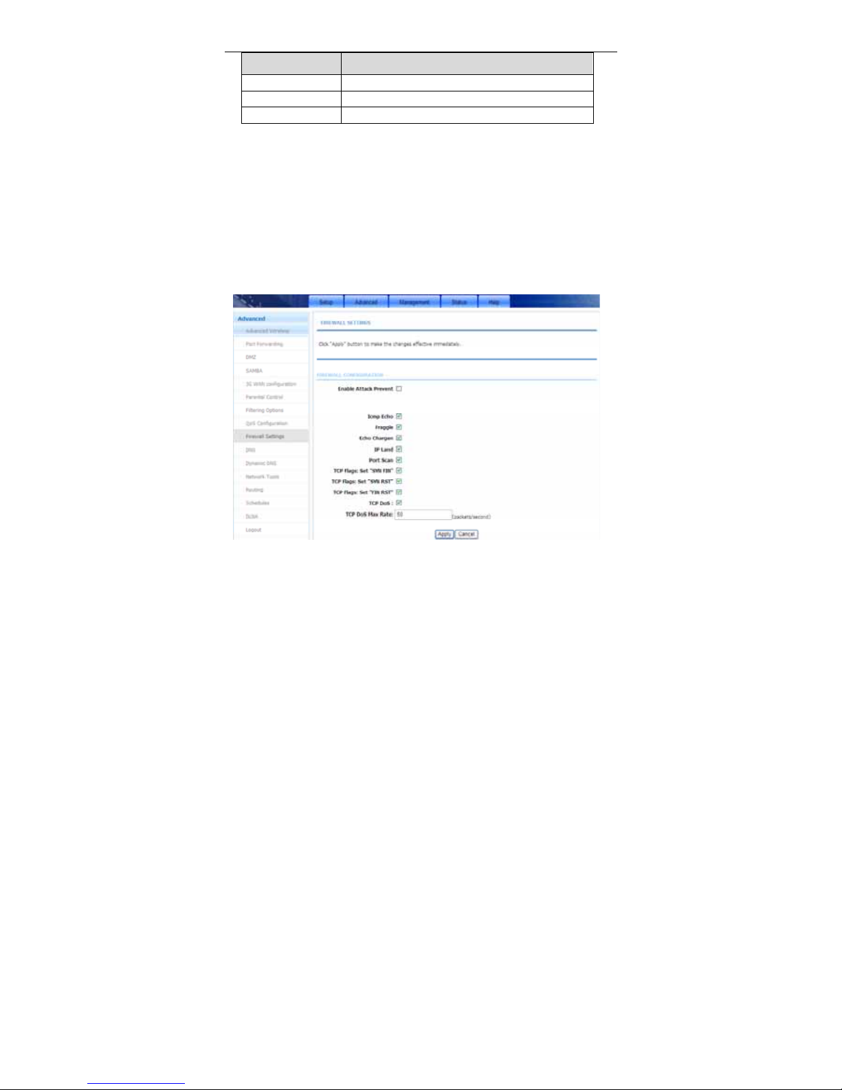
3.3.9 Firewall Settings
A denial-of-service (DoS) attack is characterized by an explicit attempt by
attackers to prevent legitimate users of a service from using that service.
Port scan protection is designed to block attempts to discover vulnerable ports or
services that might be exploited in an attack from the WAN.
Choose Advanced > Firewall Settings. The page shown in the following figure
appears.
Click Apply to save the settings.
Page 68
User Manual
65
3.3.10 DNS
Domain name system (DNS) is an Internet service that translates domain names
into IP addresses. Because domain names are alphabetic, they are easier to
remember. The Internet, however, is actually based on IP addresses. Each time
you use a domain name, a DNS service must translate the name into the
corresponding IP address. For example, the domain name www.example.com
might be translated to 198.105.232.4.
The DNS system is, in fact, its own network. If one DNS server does not know
how to translate a particular domain name, it asks another one, and so on, until
the correct IP address is returned.
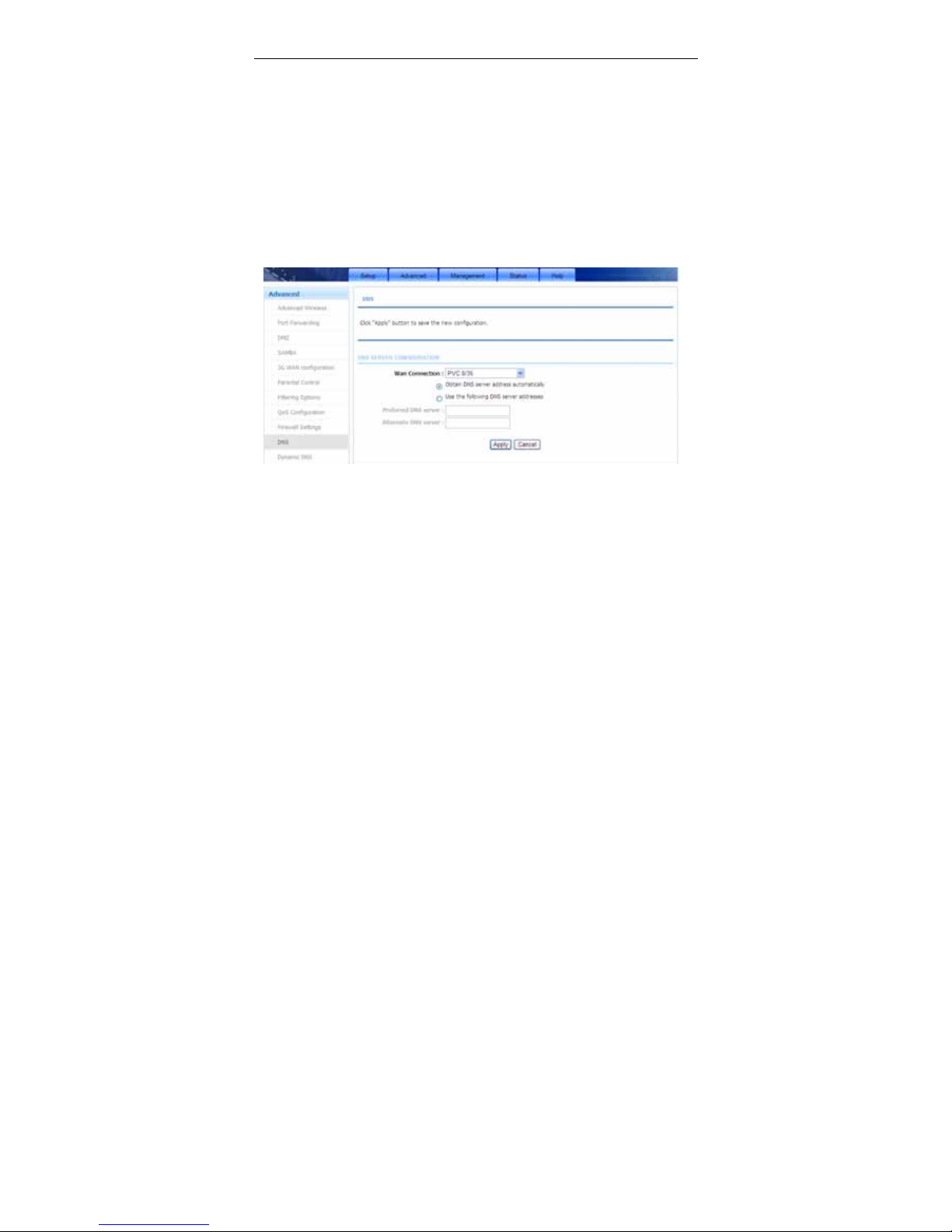
Choose Advanced > DNS. The page shown in the folllowin g figure appears.
If you are using the device for DHCP service on the LAN or using DNS servers on
the ISP network, select Obtain DNS server address automatically.
If you have DNS IP addresses provided by your ISP, enter these IP addresses in
the available entry fields for the preferred DNS server and the alternate DNS
server.
Click Apply to save the settings.
3.3.11 Dynamic DNS
The device supports dynamic domain name service (DDNS). The dynamic DNS
service allows a dynamic public IP address to be associated with a static host
name in any of the many domains, and allows access to a specified host from
various locations on the Internet. Click a hyperlinked URL in the form of
Page 69
User Manual
66
hostname.dyndns.org and allow remote access to a host. Many ISPs assign
public IP addresses using DHCP, so locating a specific host on the LAN using the
standard DNS is difficult. For example, if you are running a public web server or
VPN server on your LAN, DDNS ensures that the host can be located from the
Internet even if the public IP address changes. DDNS requires that an account
be set up with one of the supported DDNS service providers (DyndDNS.org or
dlinkddns.com).
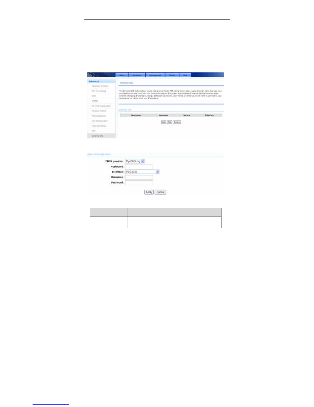
Choose Advanced > Dynamic DNS. The page shown in the following figure
appears.
Click Add to add dynamic DNS. The page shown in the following figure appears.
The following table describes the parameters of this page.
Field Description
DDNS provider
Select one of the DDNS registration organizations
from the down-list drop. Available servers include
Page 70
User Manual
67
Field Description
DynDns.org and dlinkddns.com.
Host Name
Enter the host name that you registered with your
DDNS service provider.
Username Enter the user name for your DDNS account.
Password Enter the password for your DDNS account.
Click Apply to save the settings.
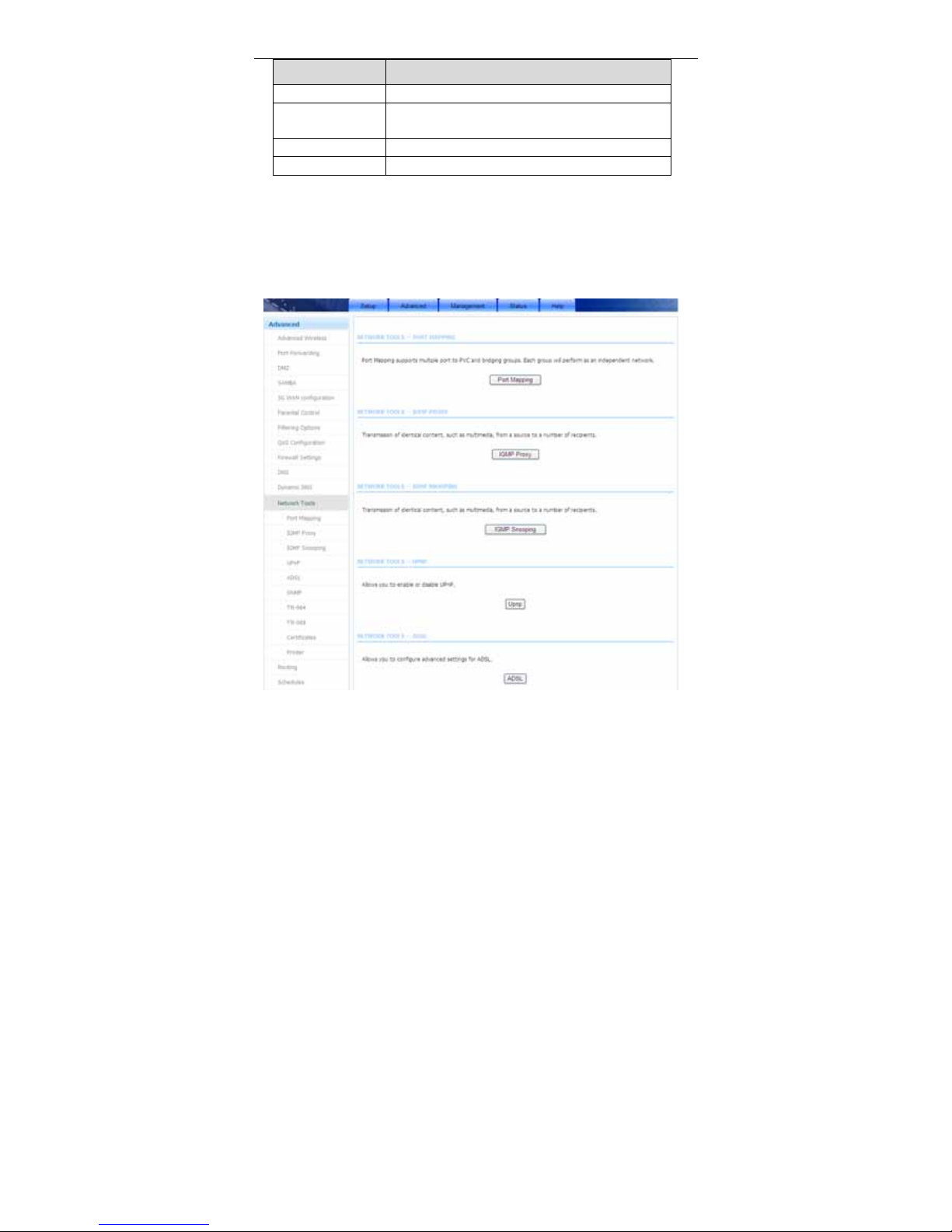
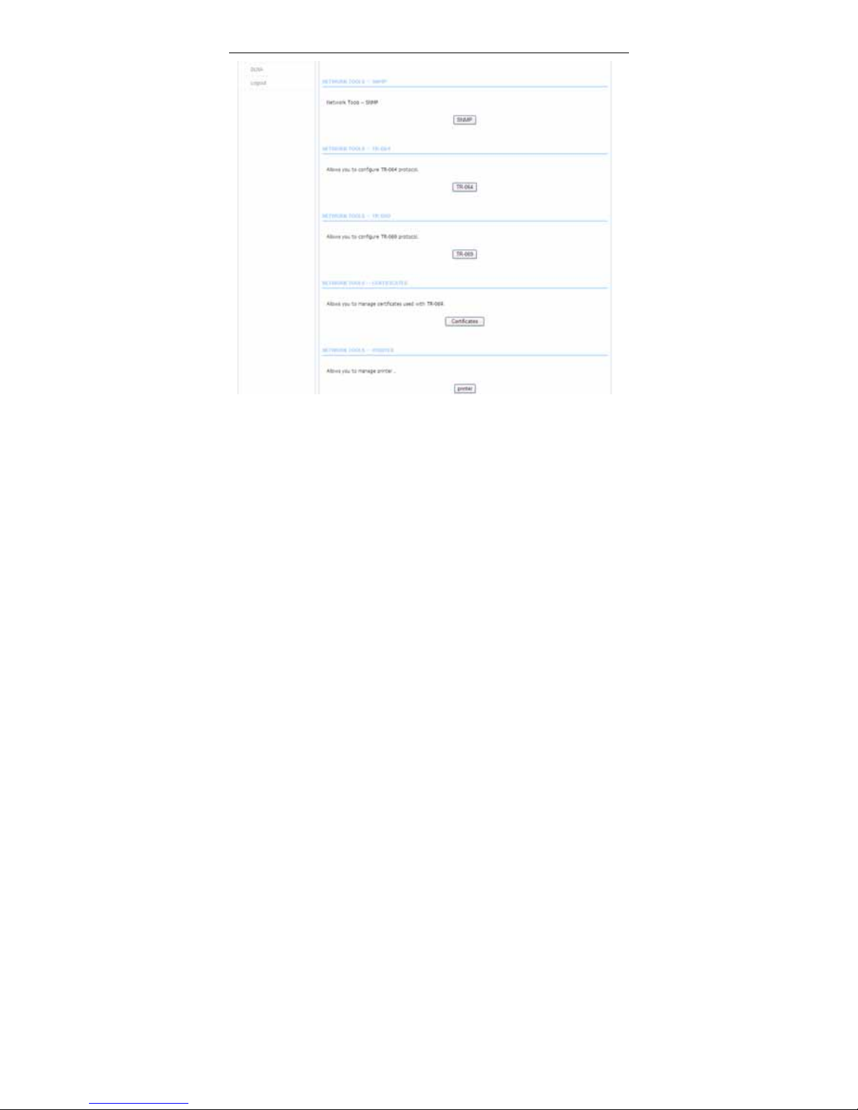
3.3.12 Network Too l s
Choose Advanced > Netw ork Tools. Th e page shown in the following figure
appears.
Page 71
User Manual
68
3.3.12.1 Port Mapping
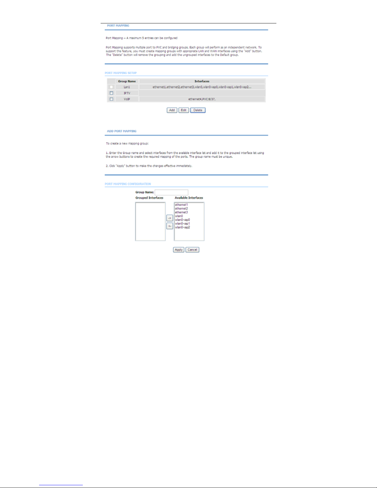
Choose Advanced > Network Tools and click Port Mapping. The page shown
in the following figure appears. In this page, you can bind the WAN interface and
the LAN interface to the same group.
Page 72
User Manual
69
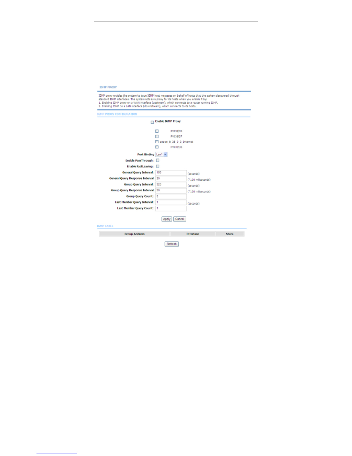
Click Add to add port mapping. The page shown in the following figure appears.
The procedure for creating a mapping group is as follows:
Step 1 Enter the group name.
Page 73
User Manual
70
Step 2 Select interfaces from the Available Interface list and click the <-
arrow button to add them to the grouped interface list, in order to
create the required mapping of the ports. The group name must be
unique.
Step 3 Click Apply to save the settings.
3.3.12.2 IGMP Proxy
Choose Advanced > Netw ork Tools and click IGMP Proxy. The page shown in
the following figure appears.
Page 74

User Manual
71
IGMP proxy enables the system to issue IGMP host messages on behalf of hosts
that the system discovered through standard IGMP interfaces. The system acts
as a proxy for its hosts after you enable it.
The following table describes the parameters of this page.
Field Description
Enable
PassThrough
The device preserve IP address field of the IGMP
packets when sent in upstream direction to the
DSLAM
Enable
FastLeaving
Enable the IGMP user disconnected from particular
multicast group immediately without performing the
verification procedure with IGMP GSQ messages.
General Query
Interval
The device will send query messages to check
IGMP user periodically. The unit is second.
General Query
Response Interval
The device waits for the IGMP user’s replying. The
unit is 100 * millisecond.
Group Query
Interval
The device will send multicast group query message
to check if the IGMP user is still alive. The unit is
second.
Group Query
Response Interval
The device waits for the IGMP user’s replying. The
unit is 100 * millisecond.
Group Query
Count
This parameter specifies how many times that the
device sends the multicast group query message.
Last Member
Query Interval
When the last member left, the device sent the
query messages periodically. The unit is second.
Last Member
Query Count
This parameter specifies how many times that the
device sends the query message.
Click Apply to save the settings.
3.3.12.3 IGMP Snooping
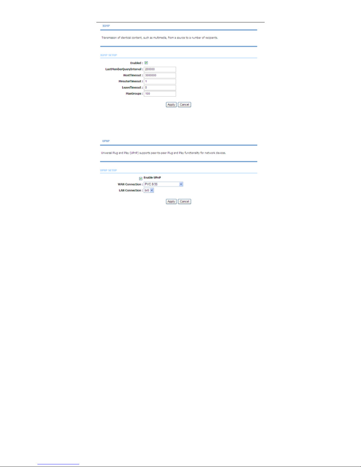
Choose Advanced > Network Tools and click IGMP Snooping. The page
shown in the following figure appears. When IGMP Snooping is enabled, the
multicast data transmits through the specific LAN port which has received the
request report.
Page 75
User Manual
72
3.3.12.4 UPnP
Choose Advanced > Network Tools and click UPnP. The page shown in the
following figure appears.
In this page, you can configure universal plug and play (UPnP). The system acts
as a daemon after you enable UPnP.
UPnP is used for popular audio visual software. It allows automatic discovery of
your device in the network. If you are concerned about UPnP security, you can
disable it. Block ICMP ping should be enabled so that the device does not
respond to malicious Internet requests.
Click Apply to save the settings.
Page 76
User Manual
73
3.3.12.5 ADSL
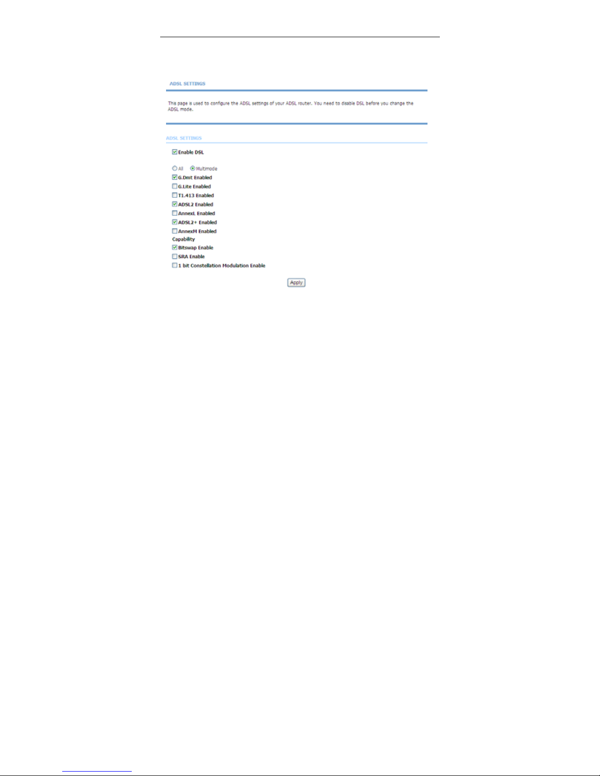
Choose Advanced > Network Tools and click ADSL. The page shown in the
following figure appears.
In this page, you can select the DSL modulation. Normally, you can remain this
factory default setting. The device negotiates the modulation mode with DSLAM.
Click Apply to save the settings.
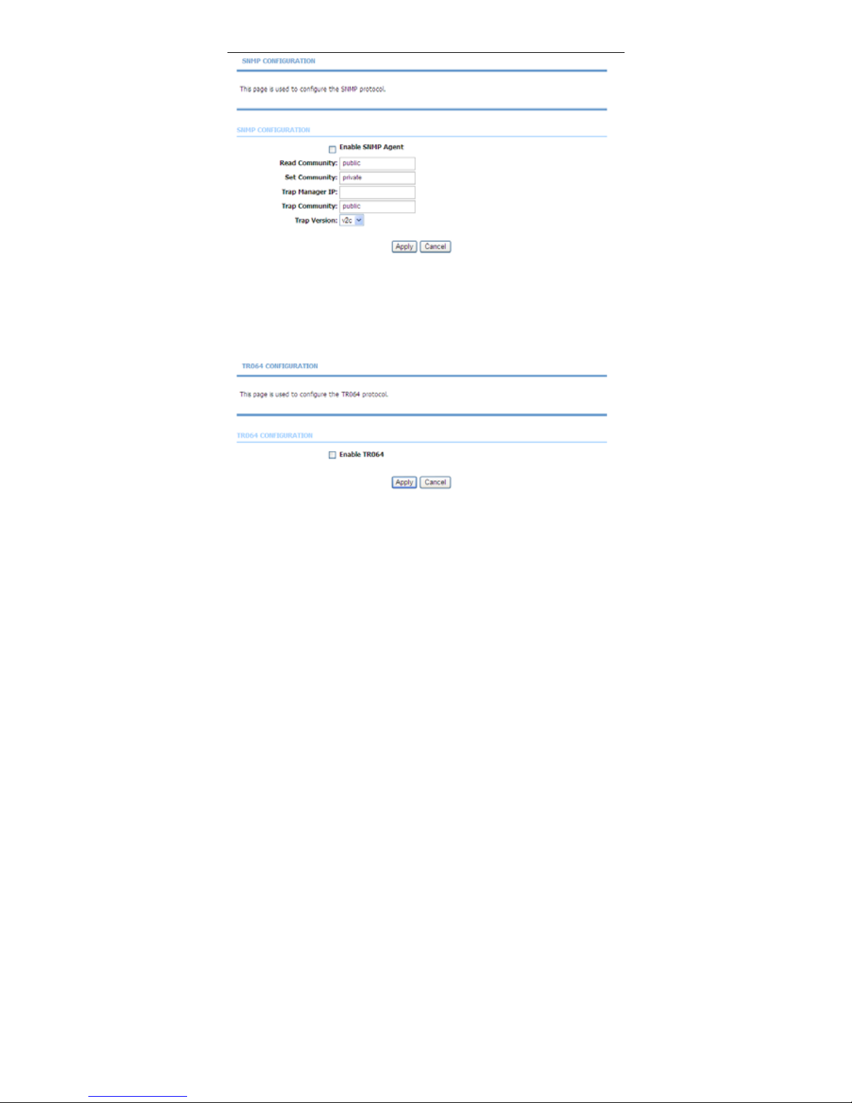
3.3.12.6 SNMP
Choose Advanced > Network Tools and click SNMP. The page shown in the
following figure appears. In this page, you can set SNMP parameters.
Page 77
User Manual
74
Click Apply to save the settings.
3.3.12.7 TR-064
Choose Advanced > Netw ork Tools and click TR-064. The page shown in the
following figure appears. In this page, you can enable the TR064 service.
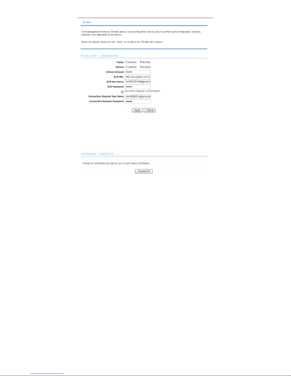
3.3.12.8 TR-069
Choose Advanced > Network Tools and click TR069. The page shown in the
following figure appears. In this page, you can configure the TR069 CPE.
Page 78
User Manual
75
Click Apply to save settings.
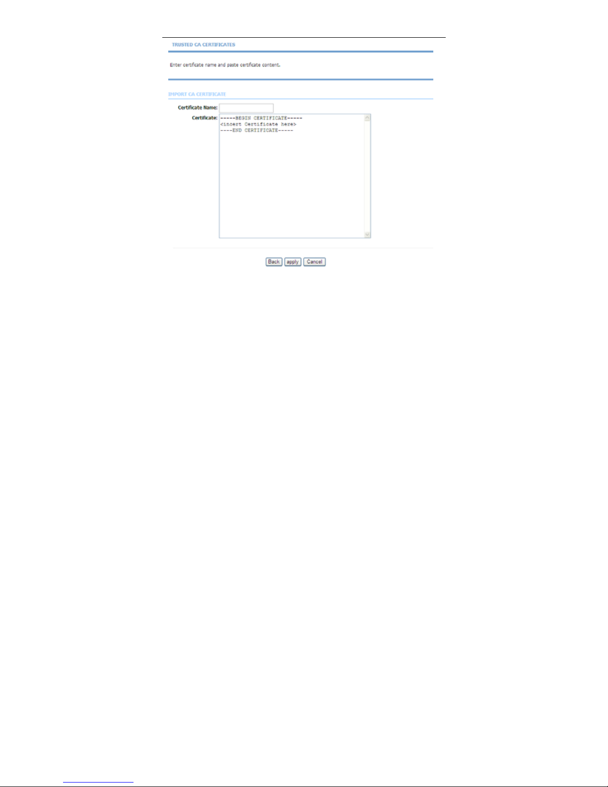
3.3.12.9 Certificates
Choose Advanced > Netw ork Tools and click Certificates. The Certificates
page shown in the following figure appears.
Click Trusted CA button to import a certificate.
Page 79
User Manual
76
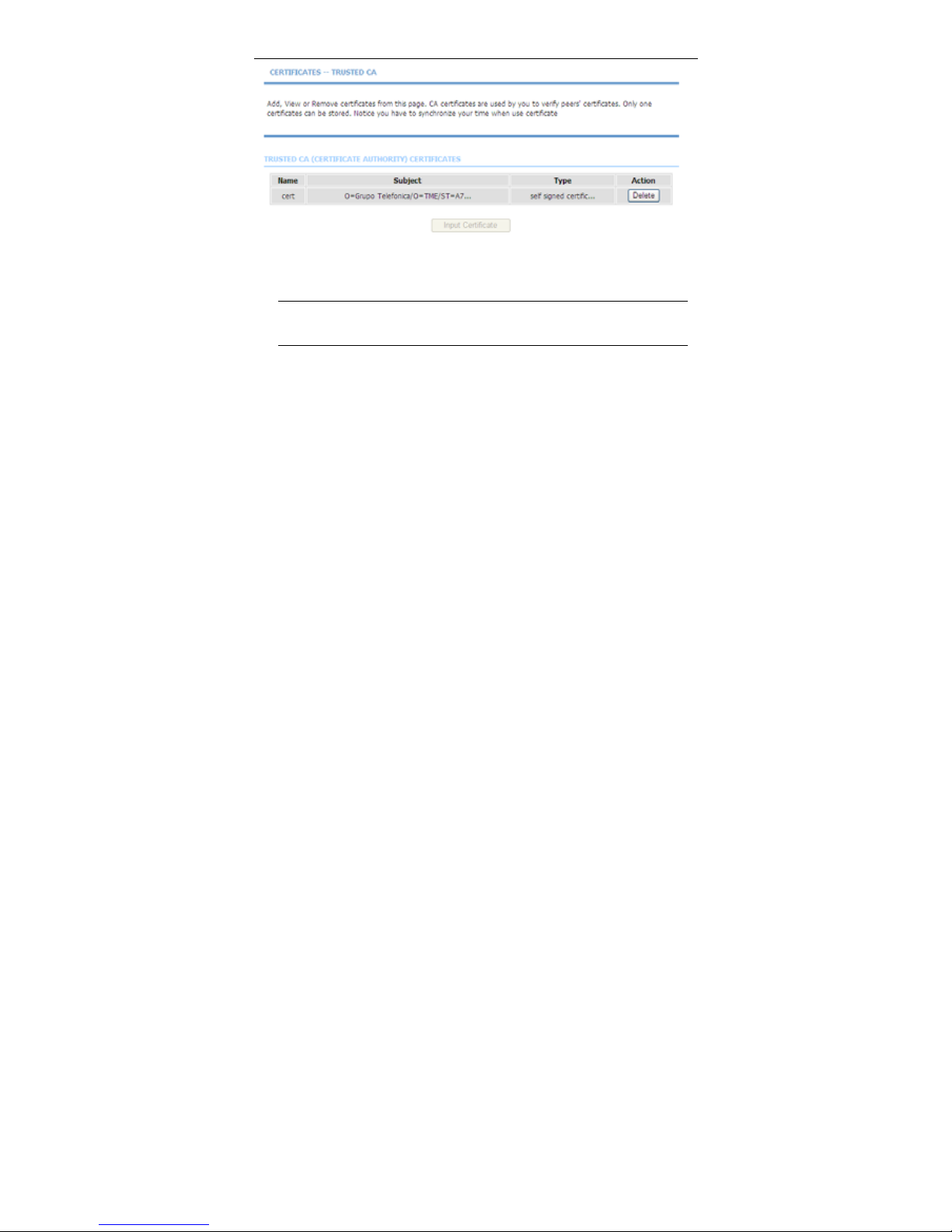
Click Input Certificate button to import a certification.
Note:
You can input a certificate after deleting the existing certificate.
Page 80
User Manual
77
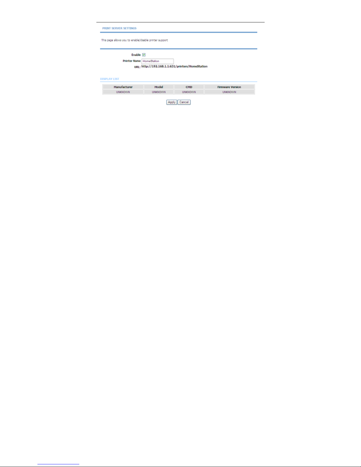
3.3.12.10 Printer
Choose Advanced > Netw ork Tools and click Printer. The Printer page shown
in the following figure appears. In this page, you can enable/disable printer
support.
Page 81
User Manual
78
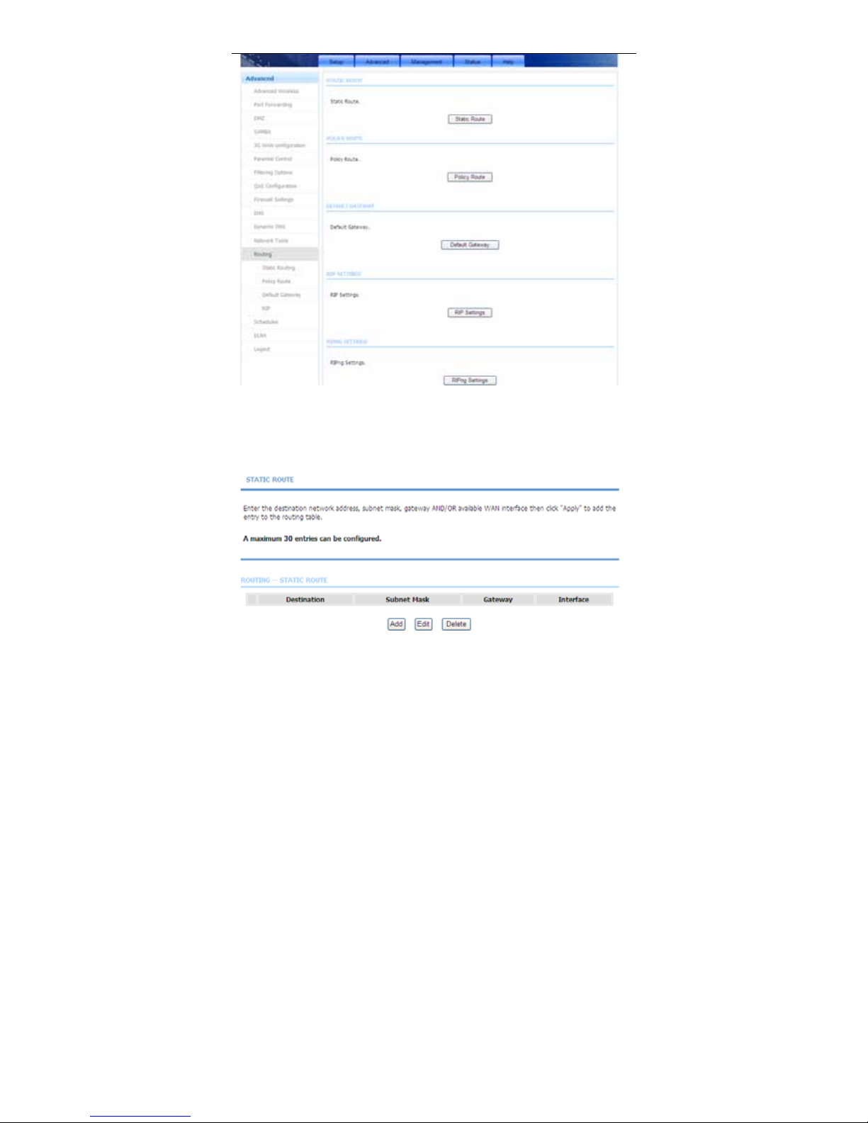
3.3.13 Routing
Choose Advanced > Routing. The page shown in the following figure appears.
Page 82
User Manual
79
3.3.13.1 Static Route
Choose Advanced > Routing and click Static Route. The page shown in the
following figure appears. This page is used to configure the routing information.
In this page, you can add or delete IP routes.
Page 83
User Manual
80
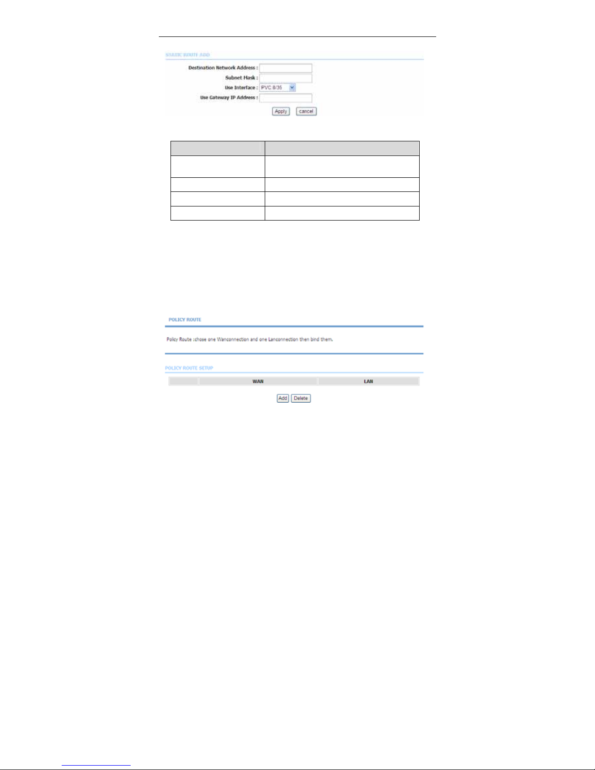
Click Add to add a static route. The page shown in the following figure appears.
The following table describes the parameters of this page.
Field Description
Destination Network
Address
The destination IP address of the router.
Subnet Mask The subnet mask of the destination IP
Use Interface The interface name of the router output port.
Use Gateway IP Address The gateway IP address of the router.
Click Apply to save the settings.
3.3.13.2 Policy Route
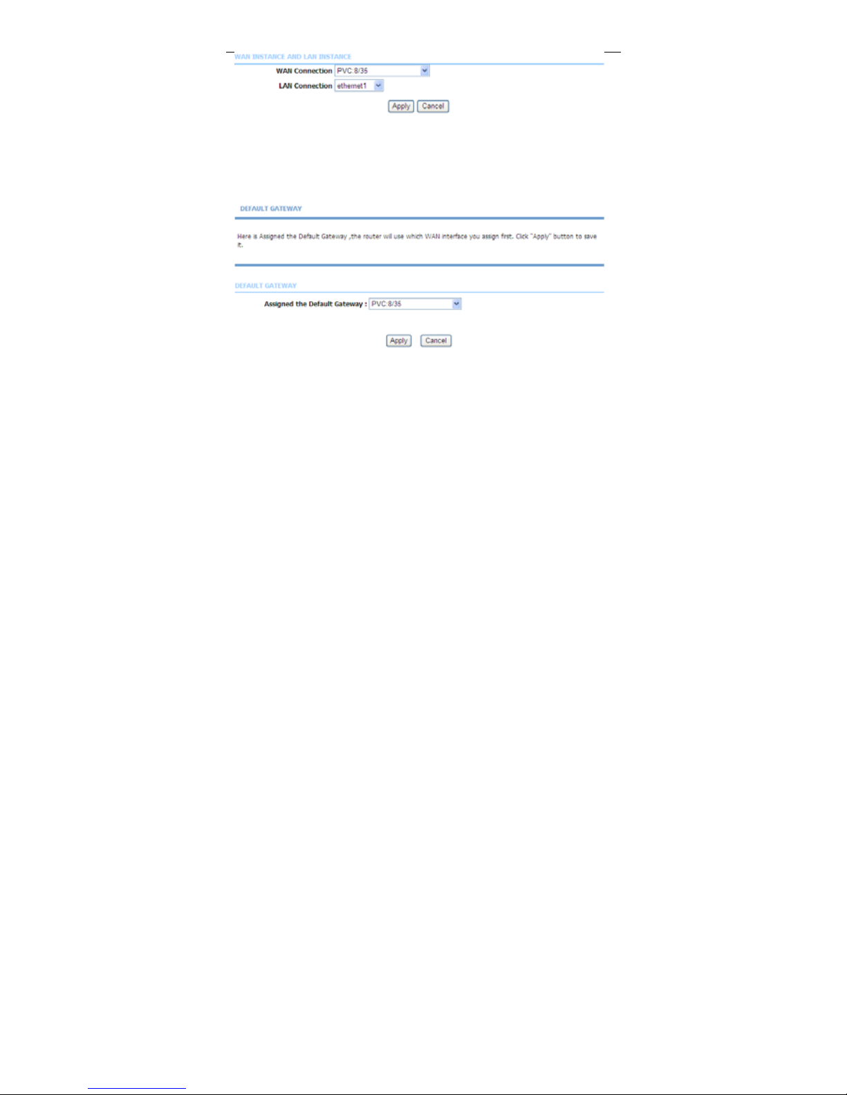
Choose Advanced > Routing and click Polic y Route. The page shown in the
following figure appears. The policy route binds one WAN connection and one
LAN interface.
Click add, the page shown in the following figure appears.
Page 84
User Manual
81
3.3.13.3 Default Gateway
Choose Advanced > Routing and click Default Gateway. The page shown in
the following figure appears. You may assign a default gateway for the router to
use first.
Click Apply to save the settings.
3.3.13.4 RIP
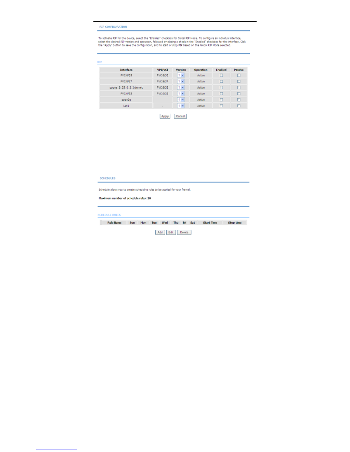
Choose Advanced > Routing and click RIP Settings. The page shown in the
following figure appears. This page is used to select the interfaces on your device
that use RIP and the version of the protocol used.
Page 85
User Manual
82
If you are using this device as a RIP-enabled device to communicate with others
using the routing information protocol, enable RIP and click Apply to save the
settings.
3.3.14 Schedules
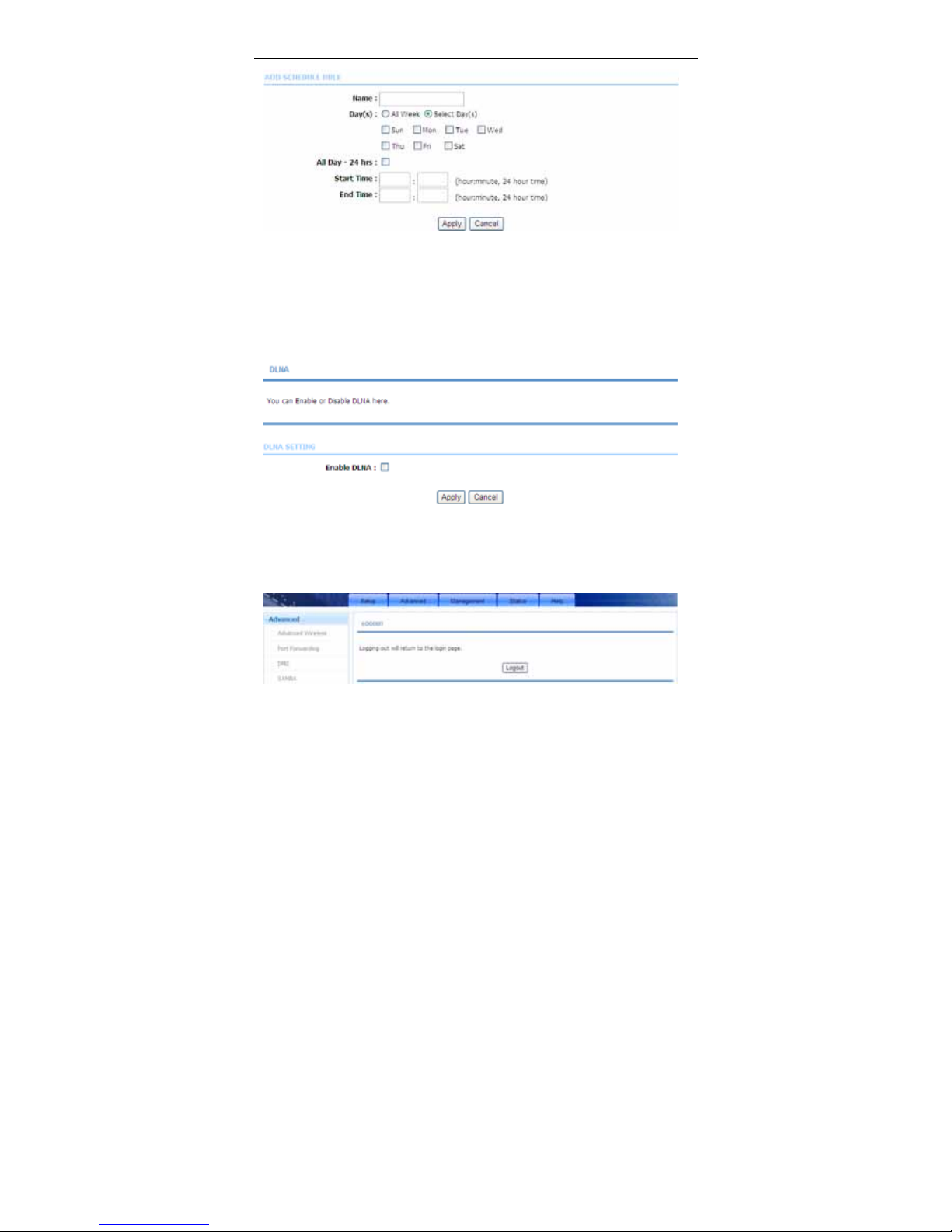
Choose Advanced > Schedules. The page shown in the following figure
appears.
Click Add to add schedule rule. The page shown in the following figure appears.
Page 86
User Manual
83
Click Apply to save the settings.
3.3.15 DLNA
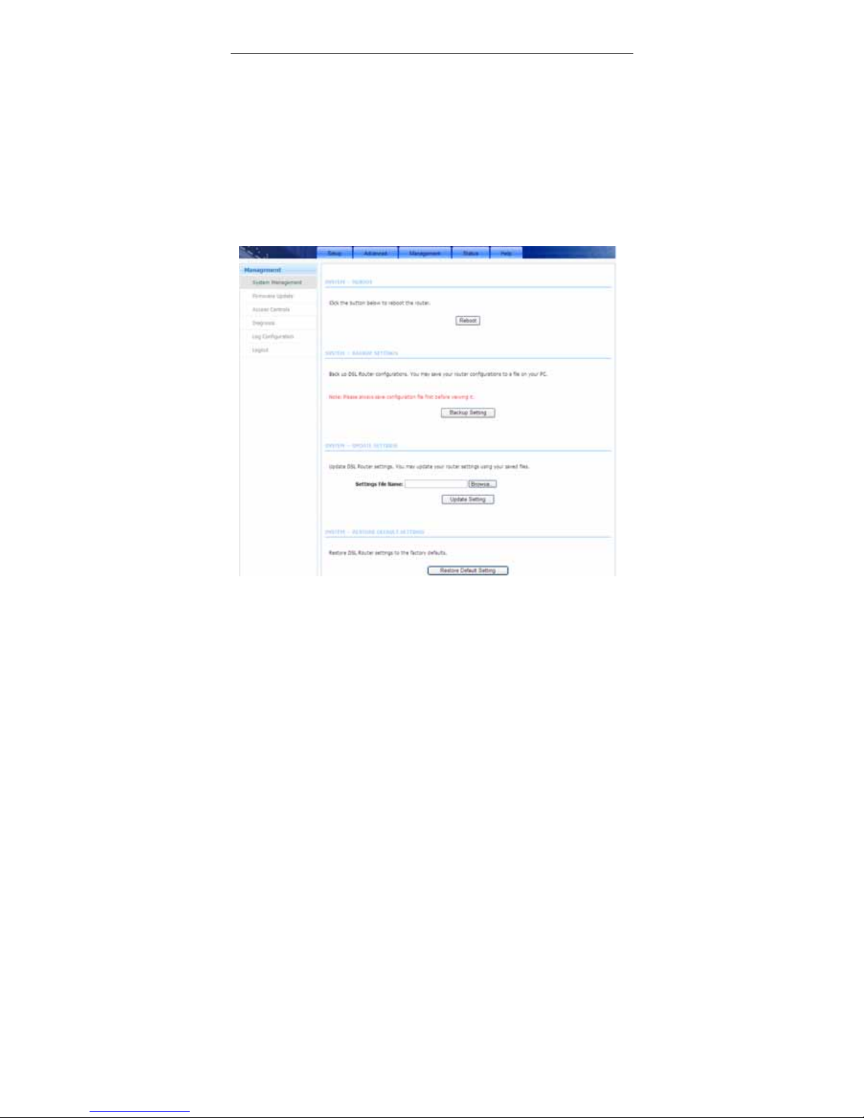
Choose Advanc ed > DLNA. The page shown in the following figure appears. In
this page, you can choose to enable DLNA and click Apply.
3.3.16 Logout
Choose Advanced > Logout. The page shown in the following figure appears. In
this page, you can log out of the configuration page.
Page 87
User Manual
84
3.4 Management
In the main interface, click Management tab to enter the Management menu as
shown in the following figure. The submenus are System Management,
Firmware Update, Access Controls, Diagnosis, Log Configuration and
Logout.
3.4.1 System Management
Choose Management > System Management. The page shown in the following
figure appears.
In this page, you can reboot device, back up the current settings to a file, update
settings from the file saved previously and restore the factory defaults.
The buttons in this page are described as follows.
Page 88
User Manual
85
Field Description
Reboot Click this button to reboot the device.
Backup Setting Click this button to save the settings to the local hard
drive. Select a location on your computer to back up
the file. You can name the configuration file.
Update setting
Click Browse to select the configuration file of device
and then click Update Settings to begin updating the
device configuration.
Restore Default
Setting
Click this button to reset the device to default settings.
Note:
Do not turn off your device or press the Reset button while an
operation in this page is in progress.
3.4.2 Firmware Update
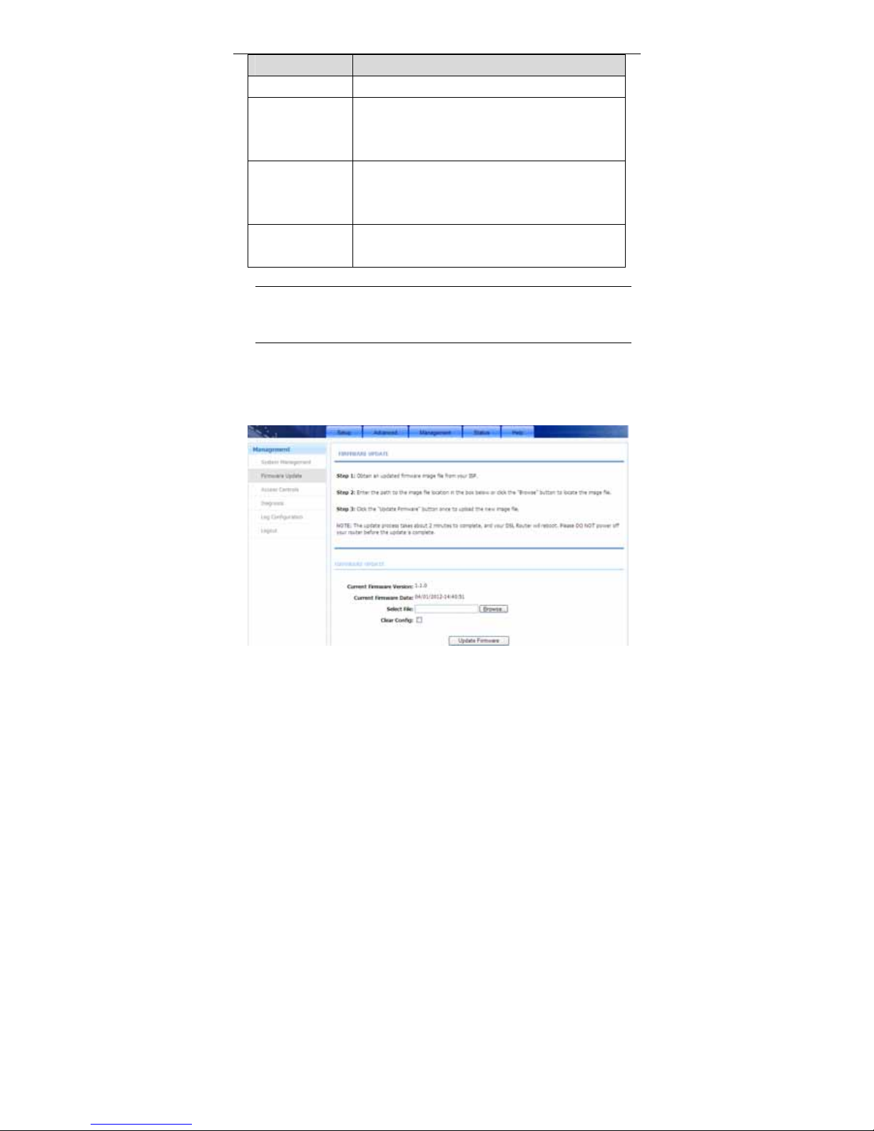
Choose Management > Firmware Update. The page shown in the following
figure appears. In this page, you can upgrade the firmware of the device.
Page 89
User Manual
86
To update the firmware, take the following steps.
Step 1 Click Browse…to find the file.
Step 2 Select Click Config.
Step 3 Click Update Firmware to copy the file.
The device loads the file and reboots automatically.
Note:
Do not turn off your device or press the Reset button while an
operation in this page is in progress.
3.4.3 Access Controls
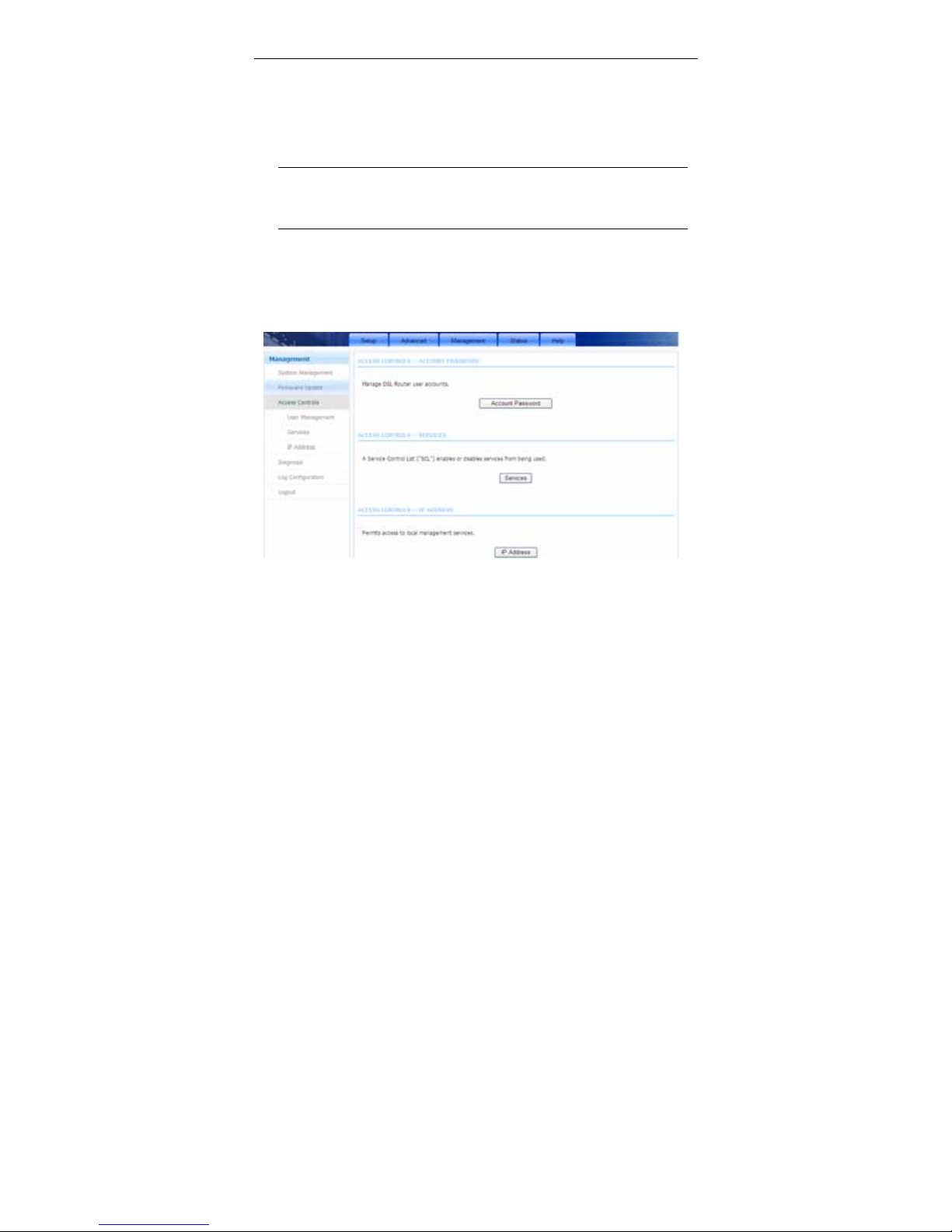
Choose Management > Access Controls. The Access Controls page shown
in the following figure appears. The page contains User Management, Services
and IP Address.
3.4.3.1 Account Password
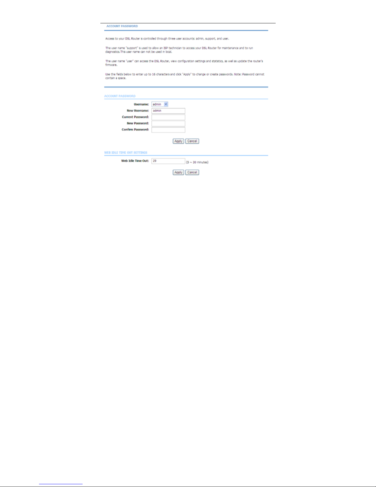
In the Access Controls page, click Account Password. The page shown in the
following figure appears. In this page, you can change the password of the user
and set time for automatic logout.
Page 90
User Manual
87
Y ou should change the default p assw ord to secure your network. Ensure that you
remember the new password or write it down and keep it in a safe and separate
location for future reference. If you forget the password, you need to reset the
device to the factory default settings and all configuration settings of the device
are lost.
Select the Username from the drop-down list. You can select admin, user or
support.
Enter the current and new passwords and confirm the new password to change
the password. Click Apply to apply the settings.
3.4.3.2 Services
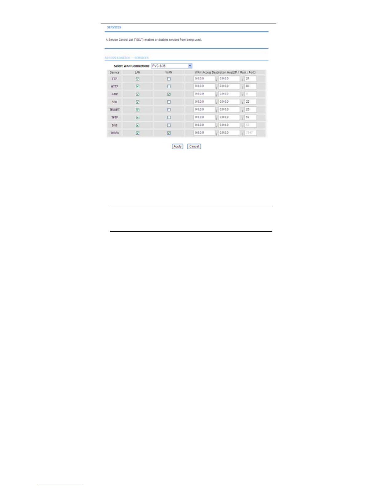
In the Access Controls page, click Services. The page shown in the following
figure appears.
Page 91
User Manual
88
In this page, you can enable or disable the services that are used by the remote
host. For example, if telnet service is enabled and port is 23, the remote host can
access the device by telnet through port 23. Normally, you need not change the
settings.
Select the management services that you want to enable or disable on the LAN
or WAN interface. Click Apply to apply the settings.
Note:
If you disable HTTP service, you cannot access the configuration
page of the device any more.
3.4.3.3 IP Address
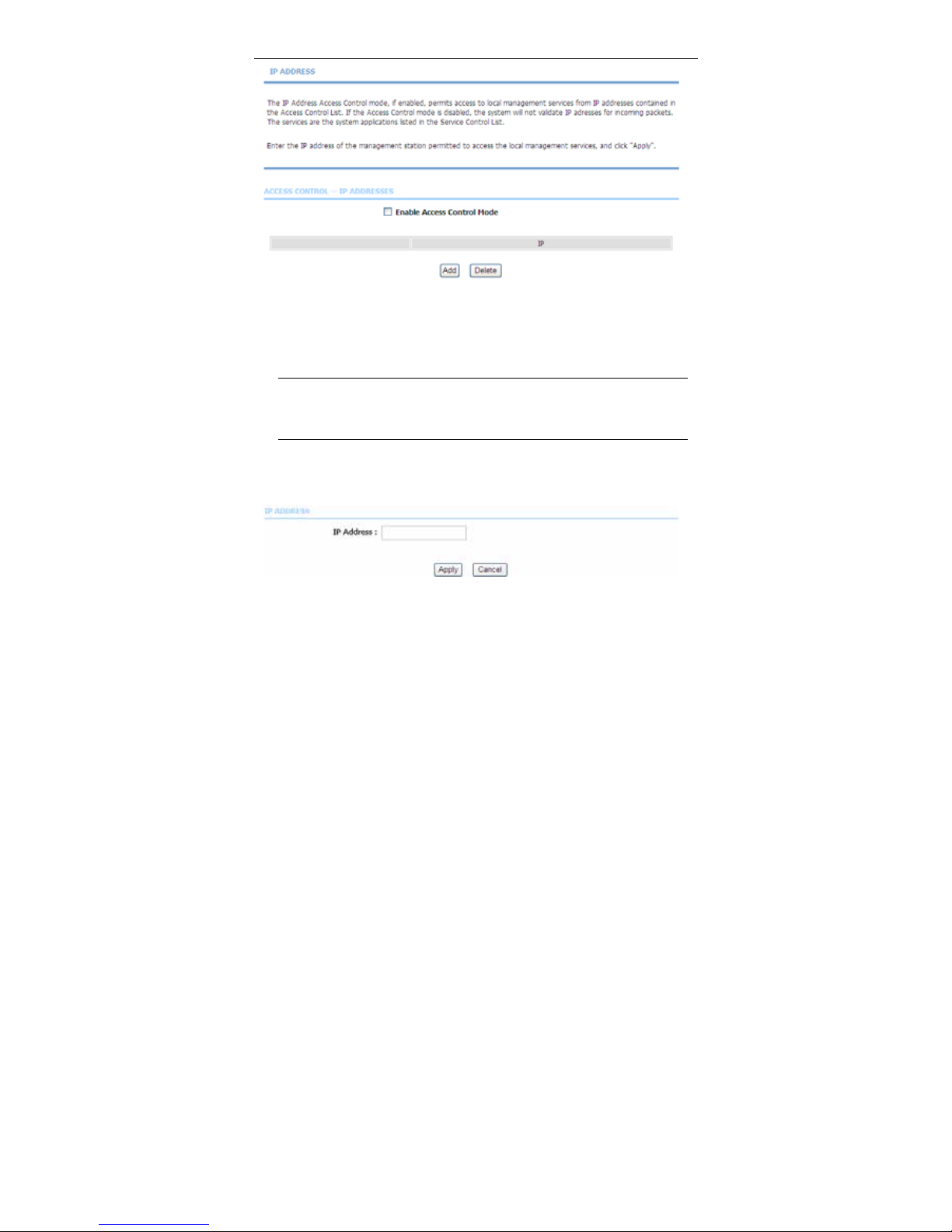
In the Access Controls page, click IP Address. The page shown in the following
figure appears.
Page 92
User Manual
89
In this page, you can configure the IP address for access control list (ACL). If ACL
is enabled, only devices with the specified IP addresses can access the device.
Tick Enable Access Control Mode to enable ACL.
Note:
If you enable the ACL, ensure that IP address of the host is in the ACL
list.
To add an IP address to the IP list, cick Add. The page shown in the following
figure appears.
Click Apply to apply the settings.
3.4.4 Diagnosis
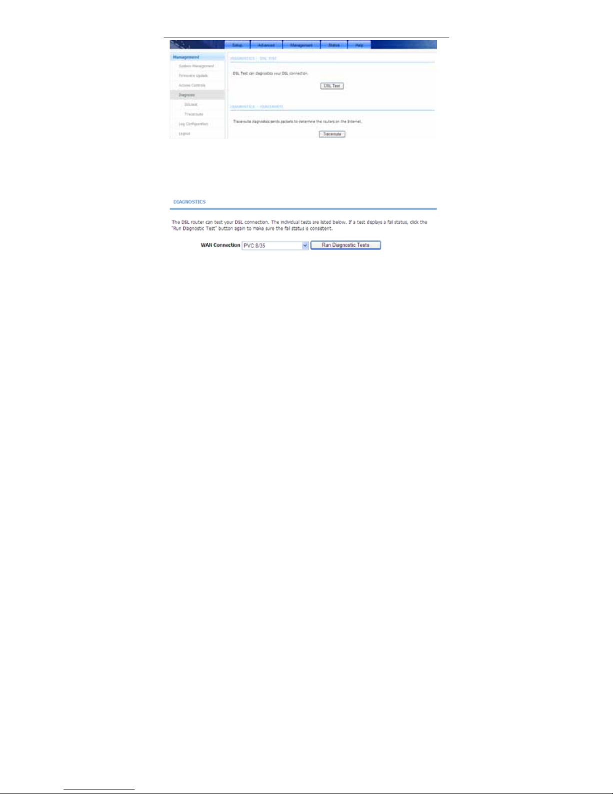
Choose Management > Diagnosis. The Diagnosis page shown in the following
figure appears. The page contains DSL Test and Traceroute.
Page 93
User Manual
90
3.4.4.1 DSL Test
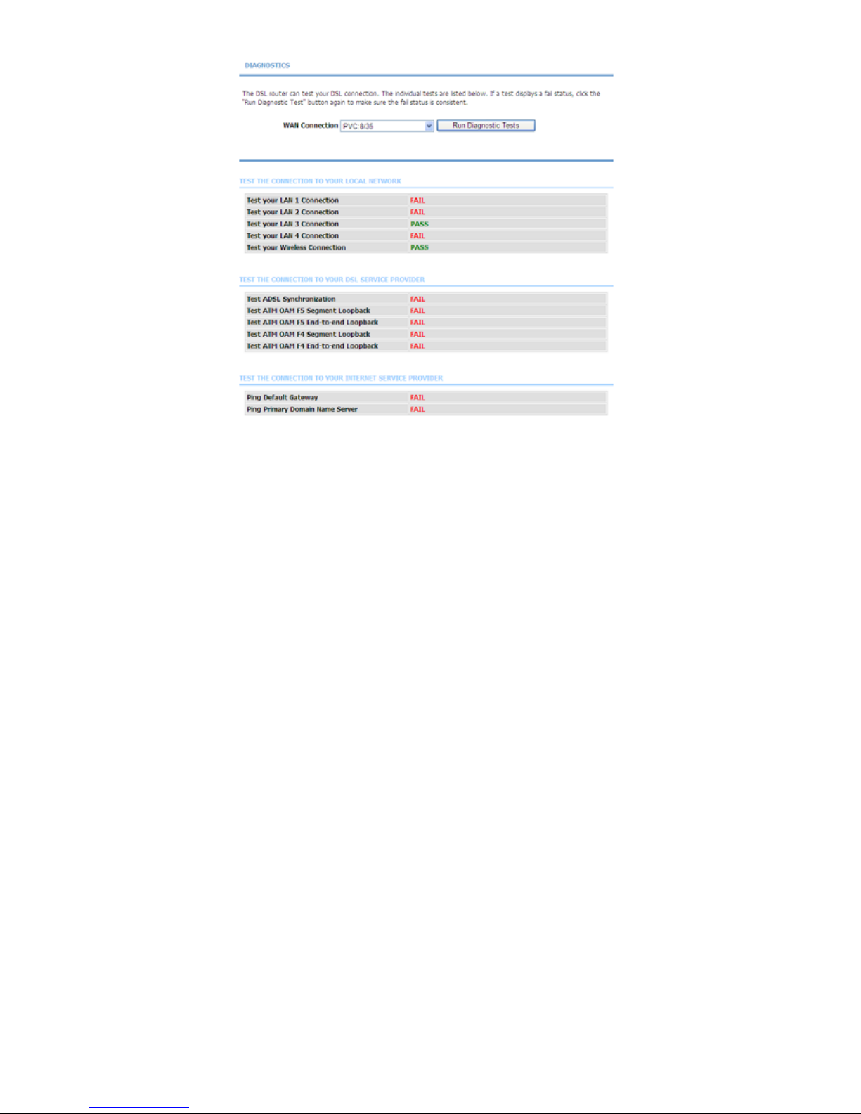
In the Diagnosis page, click DSL Test. The page shown in the following figure
appears. In this page, you can test your DSL connection.
Click Run Diagnostic Tests. After testing, the following figure appears.
Page 94
User Manual
91
3.4.4.2 Traceroute
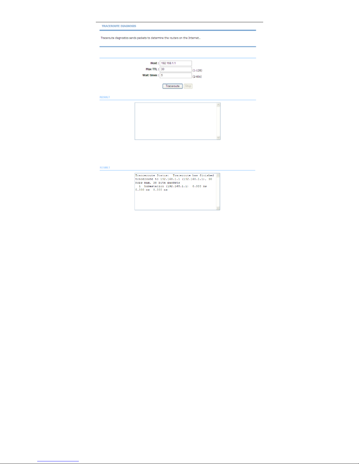
In the Diagnosis page, click Traceroute. The page shown in the following figure
appears. In this page, you can determine the routers on the Internet by sending
packets.
Page 95
User Manual
92
Click Traceroute to begin diagnosis. After finish, the page shown in the following
figure appears.
3.4.5 Log Configuration
Choose Management > Log Configuration. The System Log page shown in
the following figure appears.
Page 96

User Manual
93
This page displays event log data in the chronological manner. You can read the
event log from the local host or send it to a system log server. Available event
severity levels are as follows: Emergency, Alert, Critical, Error, Warning, Notice,
Informational and Debugging. In this page, you can enable or disable the system
log function.
To log the events, take the following steps.
Step 1 Select Enable Log check box.
Step 2 Select the display mode from the Mode drop-down list.
Step 3 Enter the Server IP Address and Server UDP Port if the Mode is set
to Both or Remote.
Step 4 Click Apply to apply the settings.
Step 5 Click View System Log to view the detail information of system log.
3.4.6 Logout
Choose Management > Logout. The page shown in the following figure appears.
In this page, you can log out of the configuration page.
Page 97

User Manual
94
3.5 Status
In the main interface, click Status tab to enter the Status menu as shown in the
following figure. The submenus are Device Info, Wireless Clients, DHCP
clients, Logs, Statistics, Route Info and Logout. You can view the system
information and monitor performance.
3.5.1 Device Info
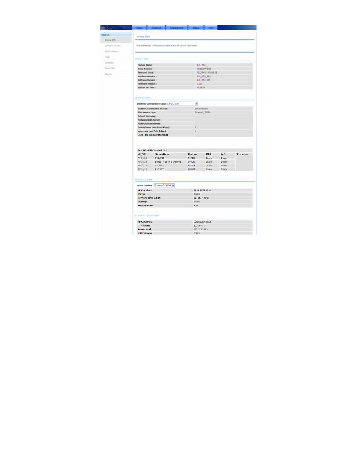
Choose Status > Device Info. The page shown in the following figure appears.
Page 98
User Manual
95
The page displays the summary of the device status. It includes the information
of firmware version, upstream rate, downstream rate, uptime and Internet
configuration (both wireless and Ethernet statuses).
Page 99
User Manual
96
3.5.2 Wireless Clients
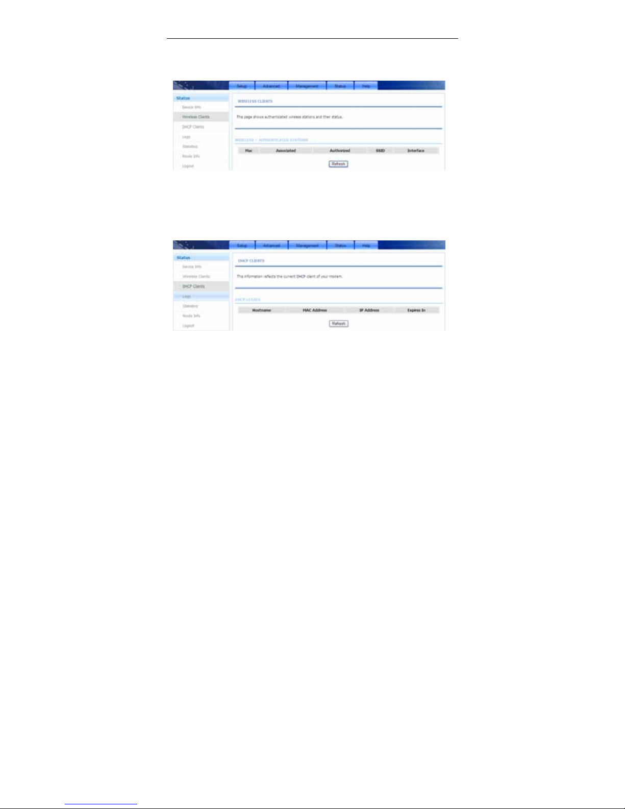
Choose Status > Wireless Clients. The page shown in the following figure
appears. The page displays authenticated wireless stations and their statuses.
3.5.3 DHCP Clients
Choose Status > DHCP Clients. The page shown in the following figure appears.
This page displays all client devices that obtain IP addresses from the device.
You can view the host name, IP address, MAC address and time expired(s).
3.5.4 Logs
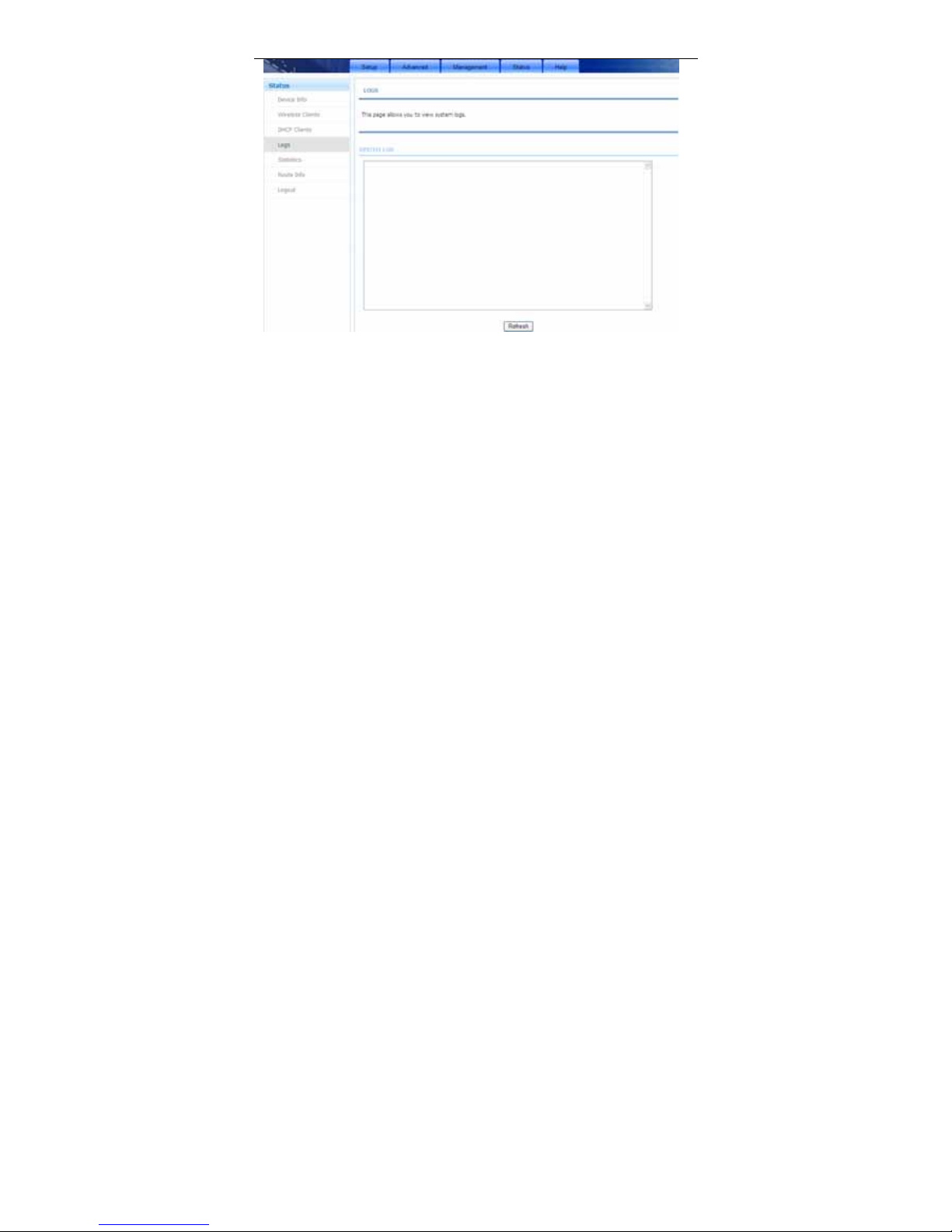
Choose Status > Logs. The page shown in the following figure appears. This
page lists the system log. Click Refresh to refresh the system log shown in the
table.
Page 100
User Manual
97
3.5.5 Statistics
Choose Status > Statistics. The page shown in the following figure appears.
This page displays the statistics of the network and data transfer. This
information helps technicians to identify if the device is functioning properly. The
information does not affect the function of the device.
 Loading...