

Page 1
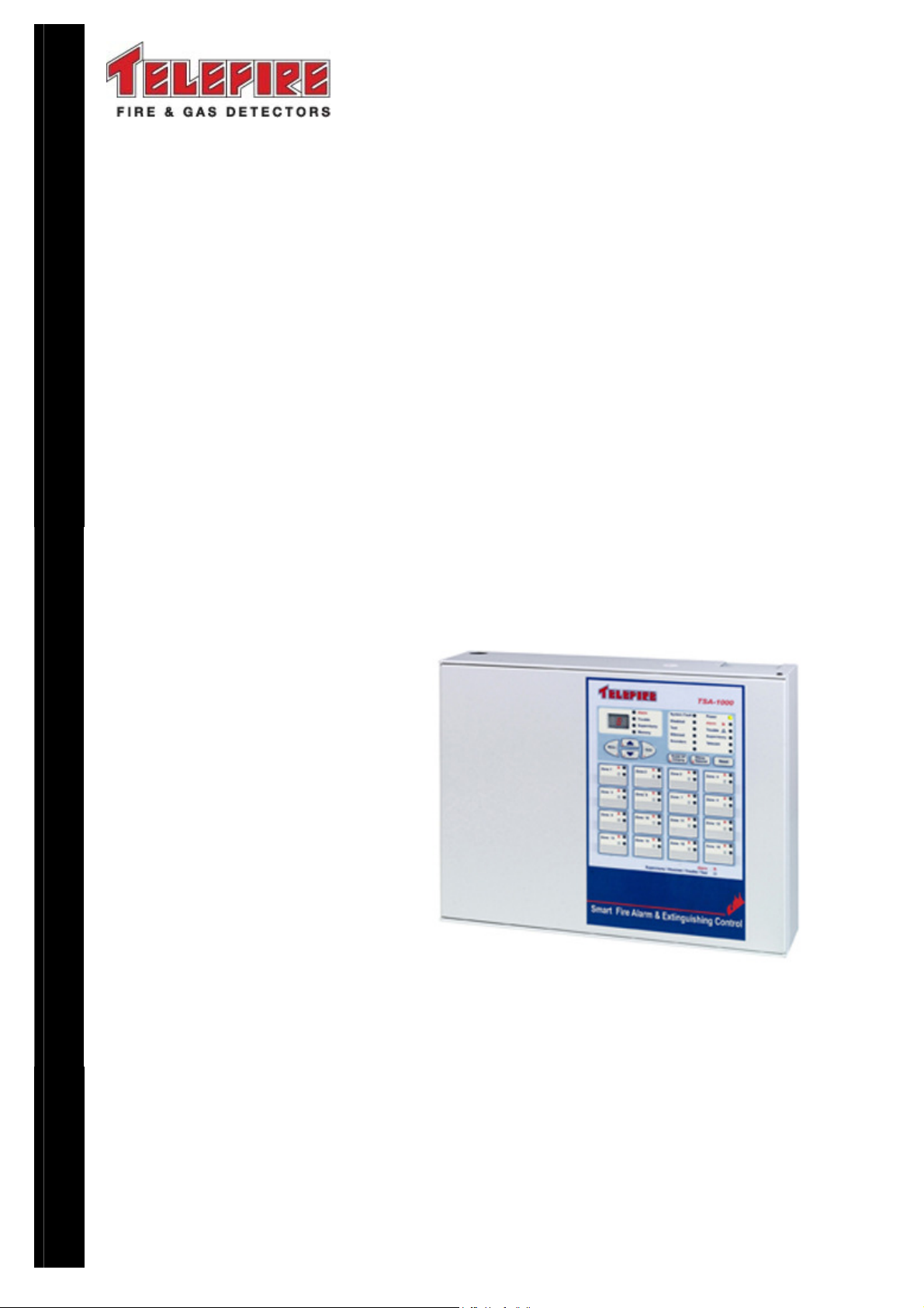
TSA-1000
Conventional
Multi-Zone
Fire Alarm and Extinguishing
Control Panels
Control Panel
Technical Manual
T
ELEFIRE FIRE & GAS DETECTORS LTD
PO Box 7036
Petach Tikva 49250
Israel
TSA
TSA----1000
TSATSA
1000En
10001000
En112
EnEn
112.pdf
.pdf
112112
.pdf.pdf
Revision 1.12
April 2012
Page 2

The information contained in this document is proprietary and is subject to all relevant copyright, patent and
other laws protecting intellectual property, as well as any specific agreement protecting TELEFIRE FIRE AND
GAS DETECTORS rights in the aforesaid information. Neither this document nor the information contained
herein may be published, reproduced or disclosed to third parties, in whole or in part, without the express,
prior, written permission of TELEFIRE FIRE AND GAS DETECTORS. In addition, any use of this document
or the information contained herein for any purposes other than those for which it was disclosed is strictly
forbidden.
TELEFIRE FIRE AND GAS DETECTORS reserves the right, without prior notice or liability, to make changes
in equipment design or specifications.
Information supplied by TELEFIRE FIRE AND GAS DETECTORS is believed to be accurate and reliable.
However, no responsibility is assumed by TELEFIRE FIRE AND GAS DETECTORS for the use thereof nor for
the rights of third parties, which may be effected in any way by the use thereof.
Any representation(s) in this document concerning performance of TELEFIRE FIRE AND GAS DETECTORS
TSA-1000(s) are for informational purposes only and are not warranties of future performance either express
or implied. TELEFIRE FIRE AND GAS DETECTORS standard limited warranty, stated in its sales contract or
order confirmation form, is the only warranty offered by TELEFIRE FIRE AND GAS DETECTORS in relation
thereto.
This document may contain flaws, omissions or typesetting errors; no warranty is granted nor liability assumed
in relation thereto unless specifically undertaken in TELEFIRE FIRE AND GAS DETECTORS sales contract
or order confirmation. Information contained herein is periodically updated and changes will be incorporated
into subsequent editions. If you have encountered an error, please notify TELEFIRE FIRE AND GAS
DETECTORS. All specifications are subject to change without prior notice.
i
LEGAL NOTICE
Note
Fire alarm systems are composed and assembled of different devices and
subsystems, such as control panels, annunciators, smoke detectors, heat
detectors, manual call points, extinguishing activation devices, and
annunciating devices intended to alert to fire / smoke.
Using this system does not ensure protection from or prevention of fire and/or
smoke damages, but proper use of the system may reduce fire and smoke
damages.
Proper system configuration design, including all of its components
and infrastructure, as well as proper installation according to the
manufacturers' instructions and the applicable standards – are a
conditioned precedent for the proper and efficient function of the
system.
The designer and installer should have the appropriate skills and
qualifications for performing said installation and all damages or losses
resulting from improper design and/or installation lie with the designer and/or
installer alone.
All loss or damage caused by improper action shall lie with the
originator of said improper action.
The manufacturer shall not be liable for any fire and/or fire damages caused
by fire in location where fire systems are installed and or results of direct or
indirect fire damage that may be caused to any persons and/or property
and/or third parties as a result of using the TSA-1000 and/or resulting from its
inaction.
Page 3
TSA-1000
© 2008 – 2012 Telefire Fire & Gas Detectors Ltd Revision 1.12 האיגש!אצמנ אל הינפהה רוקמ .
Record of Changes
No. Date Revision Details Author
1 25.01.2012 1.12 Update Introduction, Para 2.2 (UL),
UPDATE SYMBOLIC DIAGRAM, Update note about
reading and UNDERSTANDING this document Move
Number of adapters and extinguishant quantities to appear
after "Extinguishing Adapters"
Replace Fig. 1 with original dwg. from Ylan UPDATE
INSTRUCTIONS FOR IMMEDIATE ACTION
Note
i
i
The terms Control Panel" as used in NFPA 72 guideline and UL 864 standard
and Control and Indicating Equipment (CIE) as used in EN 54 standards are
used interchangeably throughout this manual.
Note
The terms “Trouble” as used in NFPA 72 guideline and UL 864 standard and
“Fault” as used in EN 54 standards are used interchangeably throughout this
manual
I. Reshef
i
i
Note
All maintenance and repair work performed on the TSA-200 shall be
performed by qualified and authorized personnel ONLY
Note
Do not install, operate, or maintain this product before fully reading and
thoroughly understanding this manual.
— I —
Page 4

TSA-1000
© 2008 – 2012 Telefire Fire & Gas Detectors Ltd Revision 1.12 האיגש!אצמנ אל הינפהה רוקמ .
Table of Contents
1 INTRODUCTION ............................................................................................1
2 FUNCTIONS AND OPTIONS.........................................................................3
2.1
EN 54-2 O
2.2
UL 864 ......................................................................................................... 3
3 IMPORTANT NOTES.....................................................................................4
3.1
M
ANUAL TRIGGERING
3.2
M
ANUAL TRIGGERING DEVICES
3.3
D
EPENDENCY ON MORE THAN ONE ALARM SIGNAL
3.4
T
WO ZONES COINCIDENCE
3.5
N
OTE REGARDING DEFAULT CONFIGURATION
3.6
M
AXIMUM NUMBER OF DETECTORS
3.7
S
UITABILITY OF USE IN VARIOUS ENVIRONMENTS
PTIONS WITH REQUIREMENTS
..................................................................................... 4
....................................................................... 4
............................................................................. 5
................................................................. 6
......................................................... 3
.......................................... 4
.................................................. 6
.............................................. 6
3.8
L
IMITING THE CONSEQUENCES OF FAULTS
....................................................... 6
4 TERMS, DEFINITIONS AND ABBREVIATIONS ...........................................8
4.1
A
4.2
BBREVIATIONS
T
ERMS AND DEFINITIONS
: ............................................................................................ 8
................................................................................ 8
5 SAFETY .........................................................................................................9
5.1
G
5.2
ROUNDING AND MAINS SUPPLY CONNECTION
B
ATTERIES HANDLING AND SAFETY
............................................................... 10
................................................ 9
6 ACCESS LEVELS........................................................................................11
7 TECHNICAL SPECIFICATIONS..................................................................12
7.1
M
7.2
7.3
7.4
7.5
7.6
AIN ELEMENTS, BASIC UNIT
E
XPANSION MODULES
I/O F
UNCTIONS OF THE DIFFERENT EXPANSION BOARDS/MODULES
R
ELAYS
TSA-1000C C
T
ABLE OF TECHNICAL SPECIFICATIONS,
....................................................................................................... 12
OMMUNICATION EXPANSION MODULE
.................................................................................. 12
....................................................................... 12
................ 12
....................................... 13
TSA-1000 ........................................ 14
7.7
D
EFAULT PORTS ALLOCATION AND CONFIGURATION
8 TSA-1000 CONTROL PANEL ASSEMBLY.................................................22
8.1
P
OWER SUPPLY, CHARGER AND BATTERIES
8.2
M
AIN BOARD
8.3
E
XPANSION MODULES
8.4
F
RONT DOOR
— II —
................................................................................................ 23
.................................................................................. 23
............................................................................................... 24
...................................... 21
.................................................. 22
Page 5

TSA-1000
© 2008 – 2012 Telefire Fire & Gas Detectors Ltd Revision 1.12 האיגש!אצמנ אל הינפהה רוקמ .
9 USER INTERFACE-DISPLAY AND KEYBOARD .......................................26
9.1
G
9.2
9.3
9.4
ENERAL DISPLAY AREA
D
IGITAL DISPLAY AND DIGITAL DISPLAY INDICATORS
Z
ONE INDICATORS
K
EYBOARD
.................................................................................................. 31
........................................................................................ 31
.............................................................................. 26
...................................... 30
10 WORK STATES ...........................................................................................33
10.1 N
10.2 A
10.3 F
10.4 S
10.5 D
10.6 T
ORMAL STATE
LARM STATE
AULT STATE
UPERVISORY STATE
ISABLEMENT STATE
EST STATE
........................................................................................... 33
.............................................................................................. 33
............................................................................................... 34
................................................................................................. 35
................................................................................... 34
................................................................................... 35
11 INSTALLATION ...........................................................................................36
11.1 PRE-I
11.2 M
11.3 W
11.4 I
11.5 C
11.6 P
11.7 C
NSTALLATION PLANNING
OUNTING
IRING
NSTALLING DETECTORS, INPUT AND OUTPUT DEVICES, AND OTHER DEVICES
ONNECTING THE MAINS, BATTERIES AND THE GROUND WIRE
OST-INSTALLATION
ONNECTING A
................................................................................................... 37
....................................................................................................... 38
..................................................................................... 45
TDM-500I D
....................................................................... 36
. ........................ 44
IALER
................................................................ 46
. 42
12 EXTINGUISHING .........................................................................................48
12.1 A
UTOMATIC EXTINGUISHING
......................................................................... 48
12.2 M
12.3 E
12.4 E
12.5 P
12.6 A
12.7 R
ANUAL EXTINGUISHING
XTINGUISHING OUTPUT
MERGENCY HOLD AND EMERGENCY ABORT
OST-ACTIVATION INDICATION
CTIONS TO PERFORM AFTER EXTINGUISHING ACTIVATION
EESTABLISHING THE QUIESCENT CONDITION AFTER EXTINGUISHING
.............................................................................. 48
.............................................................................. 48
...................................................................... 48
13 CONNECTING EXTINGUISHING EQUIPMENT ..........................................50
13.1 E
13.2 N
13.3 E
13.4 F
13.5 F
13.6 G
13.7 F
— III —
XTINGUISHING ADAPTERS
UMBER OF EXTINGUISHING ADAPTERS
XTINGUISHANT QUANTITIES
IKE
FIRERASER ....................................................................................... 51
IKE
GCA.................................................................................................... 52
REENEX AEROSOL CONTAINERS
IREPRO AEROSOL CONTAINERS
........................................................................... 50
........................................................................ 51
................................................. 48
............................ 49
............. 49
........................................................ 50
................................................................ 52
.................................................................. 53
Page 6

TSA-1000
© 2008 – 2012 Telefire Fire & Gas Detectors Ltd Revision 1.12 האיגש!אצמנ אל הינפהה רוקמ .
13.8 A T
YPICAL APPLICATION – EXTINGUISHING AND ELECTRICITY DISCONNECT
..... 53
14 CONTROL PANEL PROGRAMMING..........................................................55
14.1 M
14.2 E
14.3 K
14.4 D
14.5 P
14.6 D
14.7 H
14.8 E
14.9 R
14.10 N
14.11 R
14.12 Z
14.13 O
14.14 S
ENU STRUCTURE
NTERING PROGRAMMING MODE
EY FUNCTIONS DURING PROGRAMMING
ISPLAY DURING PROGRAMMING
ROGRAMMING SEQUENCE
IALER PROGRAMMING
ORN OUTPUT PROGRAMMING
XPANSION CARD PROGRAMMING
EMOTE ANNUNCIATOR PROGRAMMING
ETWORK PROGRAMMING
ELAY PROGRAMMING
ONE PROGRAMMING
UTPUT PROGRAMMING
AVING DATA AND EXITING PROGRAMMING MODE
....................................................................................... 55
.................................................................. 55
....................................................... 55
.................................................................. 56
........................................................................... 57
................................................................................ 58
..................................................................... 58
................................................................ 58
........................................................ 59
............................................................................ 59
................................................................................. 59
................................................................................... 61
............................................................................... 62
......................................... 64
15 OPERATION AND MAINTENANCE ............................................................65
15.1 E
15.2 ON / O
15.3 F
15.4 E
15.5 A
15.6 C
15.7 S
15.8 L
15.9 A
15.10 R
VACUATION
FF ZONE OR OUTPUT
IELD TEST (FT
VENT LOG
LARM COUNTER
HANGING PASSWORD
ETTING TIME AND DATE (T+D
AMP TEST (LT
DDITIONAL INFORMATION (IN
ESTORING DEFAULT CONFIGURATION (D
(EVC) ..................................................................................... 65
(OFF) ............................................................... 65
) ........................................................................................... 65
(LOG)....................................................................................... 66
(ALC)............................................................................... 66
(PAS)....................................................................... 66
)..................................................................... 66
)............................................................................................ 67
F).................................................................... 67
EF)................................................ 67
16 TROUBLESHOOTING .................................................................................68
16.1 M
16.2 S
16.3 S
16.4 P
AINTENANCE ALERT
YSTEM STATES
YSTEM FAULTS
ROGRAMMING FAULTS
................................................................................... 68
.......................................................................................... 68
.......................................................................................... 68
................................................................................ 70
17 COMMISSIONING........................................................................................72
18 MAINTENANCE ...........................................................................................74
19 ROUTINE TESTING.....................................................................................75
— IV —
Page 7

TSA-1000
© 2008 – 2012 Telefire Fire & Gas Detectors Ltd Revision 1.12 האיגש!אצמנ אל הינפהה רוקמ .
19.1 W
EEKLY INSPECTION – TO BE PERFORMED BY SITE PERSONNEL
.................... 75
20 CERTIFICATION..........................................................................................76
— V —
Page 8

TSA-1000
© 2008 – 2012 Telefire Fire & Gas Detectors Ltd Revision 1.12 האיגש!אצמנ אל הינפהה רוקמ .
Tables of Figures
Figure 1 TSA-1000 typical system 7
Figure 2 Module location 22
Figure 3 Display and Keyboard 25
Figure 4 General Display Area 26
Figure 5 Digital Display and Digital Display Indicators 31
Figure 6 Zone Indicators 31
Figure 7 Keyboard 31
Figure 8 Chassis Mounting Holes 38
Figure 9 Routing High- and Low Voltage cables in the TSA-1000 Chassis 40
Figure 10 RM-1000 connection 41
Figure 11 Connecting a network 41
Figure 12 Main Board Connectors 42
Figure 13 Expansion Module Connectors 43
Figure 14 Connecting Two Detectors and a TPB-10R Break-Glass 43
Figure 15 Connecting Programmable and General Sounders 43
Figure 16 Connecting the grounding wire to the Chassis 44
Figure 17 Connecting a TDM-500i Dialer (W/W rev C5, S/W rev 2.05.01) 46
Figure 18 Connecting a FIRERASER Cylinder for Automatic Extinguishing 51
Figure 19 Connecting a GCA-Activated Extinguishing Cylinder 52
Figure 20 Connecting a GreenEX Aerosol Extinguishing Container 52
Figure 21 Connecting FirePro Aerosol Generators 53
Figure 22 A typical application – cross-zone activation of electricity disconnect,
evacuation volume extinguishing 54
Figure 23 Programming Menu Structure 55
Figure 24 The seven-segment display and representation of digits and letters 57
Figure 25 Device selection 58
Figure 26 Display during relay programming 60
Figure 27 Programmable Relay Contacts During Normal Operations and Upon
Activation 61
Figure 28 Display during input programming 62
Figure 29 Display during output programming 63
List of Tables
Table 1
Table 2
Table 3
Table 4
— VI —
Technical Specifications 20
TSA-1000 – number of inputs and outputs of the various configurations 24
IDC cable selection 36
Wiring Characteristics’ influence on System Performance 39
Page 9

TSA-1000
© 2008 – 2012 Telefire Fire & Gas Detectors Ltd Revision 1.12 האיגש!אצמנ אל הינפהה רוקמ .
1 Introduction
Telefire's TSA-1000 Conventional (i.e. Non Addressable) Multi-Zone Fire Alarm Control
Panel complies with numerous standards. It is certified to EN 54-2 and EN 54-4. It is
also CE marked and is certified to GOST 53325-2009 and to IS 1220. It also complies
with UL 864 edition 9.
The control panel is modular and can be extended up to 16 input zones, with options for
other expansions.
The base control panel contains four programmable zones, four programmable outputs,
a horn output, a Fire Alarm dialer output, and three programmable relays.
The control panel is modular and is expandable via various modules that include inputs,
outputs, and relays to implement complex logic functions.
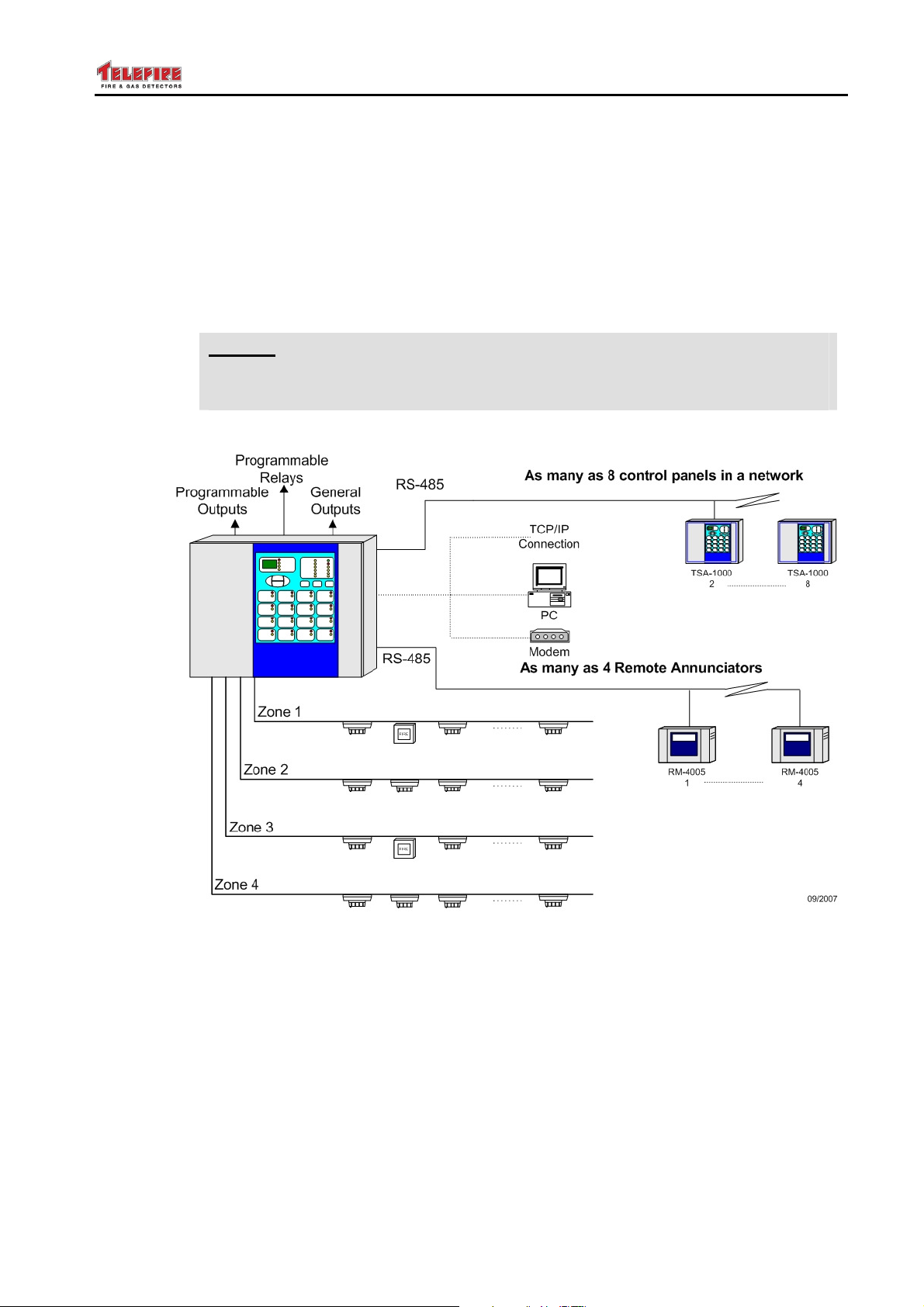
Up to four remote panels can be connected via an RS-485 interface (part of the
TSA-1000C, a communication expansion card). Computer communication and remote
panels are also supported through the TSA-1000C
The TSA-1000 supervises two-wire IDC lines ("zones") and outputs that can be used to
activate sounders, automatic extinguishing devices, evacuation sounders, or other
notification equipment. Additionally, the control panel has separate outputs for activating
a main sounder, automatic dialer, and "dry" contacts (of relays) to indicate alarm, fault,
and supervisory events of the system.
All input and output lines are fully supervised. The output lines are constantly monitored
and are automatically disconnected when current draw exceeds the allowed values.
Input and output line protection is done without the use of fuses, using Telefire's unique
ACM (Advanced Current Management) that provides high resilience even during fault
events and automatic return to normal operation with problem resolution.
Any event in the system is clearly displayed in detail and allows quick and easy
troubleshooting for the user, operator, and service technician.
All programming and configuration can be done easily through the panel's keyboard or
via dedicated software.
As the system is computerized, it allows working in various modes that can be easily
reconfigured in the field without special tools, yet allowing access only to authorized
personnel.
The TSA-1000 can be programmed as a fire alarm panel, fire alarm and extinguishing
panel that includes cross-zoning, extinguishing activation delay, or a combination of the
two. Additionally, it is possible to delay alarm from specific zones and cross zones to
neutralize false alarms from difficult locations such as areas with forklift activities, etc.
The system's inputs, outputs, and relays are fully configurable including complex logic
operations involving multiple outputs and multiple inputs.
The TSA-1000 allows output activation in four ways: general, specific zone, cross-zones
of several zones, and one of several zones, through unique matrix logic (AAM –
Advance Activation Matrix).
The system includes a maintenance alert for detectors (dependant on using Telefire
detectors), a function that required, until now, analog addressable panels.
Battery charging is fully supervised – including charging voltage, charging current, and
monitoring of the battery's ability to supply the required current.
A special work mode (Field Test) allows detector testing using only one technician,
whilst differentiating between activations that are done for testing purposes and real
alarms.
– Page 1 of 1 –
Page 10

TSA-1000
© 2008 – 2012 Telefire Fire & Gas Detectors Ltd Revision 1.12 האיגש!אצמנ אל הינפהה רוקמ .
The system supports an automatic alarm verification feature, to decrease the occurrence
of false alarms, and a time and date clock for logging system events. System log can be
viewed via a PC or printed for system investigation purposes.
The TSA-1000 can be connected to form a network of control panels.
– Page 2 of 2 –
Page 11

TSA-1000
© 2008 – 2012 Telefire Fire & Gas Detectors Ltd Revision 1.12 האיגש!אצמנ אל הינפהה רוקמ .
2 Functions and Options
2.1 EN 54-2 Options with Requirements
The TSA-1000 conforms fully to European standards BS EN 54-2:1998 and
BS EN 54-4:1998 and the following optional features:
• Output to fire alarm devices – EN 54-2 Section 7.8 option with requirements
• Output to fire alarm routing equipment – EN 54-2 Section 7.9 option with
requirements
• Output to fire protection equipment – EN 54-2 Section 7.10 option with requirements
• Coincidence detection– EN 54-2 Section 7.12 option with requirements
(Provided as a two zones coincidence and as a single/Dual zone AVF- Alarm
Verification Function)
• Alarm Counter – EN 54-2 Section 7.13 option with requirements
• Total loss of power supply – EN 54-2 Section 8.4 option with requirements
• Output to fault warning routing equipment – EN 54-2 Section 8.9 option with
requirements
• Test condition – EN 54-2 Section 10 option with requirements
2.2 UL 864
The TSA-1000 complies with UL 864 edition 9
– Page 3 of 3 –
Page 12
TSA-1000
© 2008 – 2012 Telefire Fire & Gas Detectors Ltd Revision 1.12 האיגש!אצמנ אל הינפהה רוקמ .
3 Important Notes
3.1 Manual Triggering
Any of the inputs can be configured as a manual (extinguishing) release input, or as a
Manual Call Point (i.e. Manual Alarm Input). Asserting the Manual release (i.e. pressing
the PB) causes immediate extinguishing.
Note
i
i
If a remote (non panel mounted) extinguishing manual triggering device is
used, then USE ONLY an approved and certified Extinguishing Triggering
Device of the correct color as per EN 12094-3.
Note
If a remote (non panel mounted) Manual Call Point is used, then USE ONLY
an approved and certified Device of the correct color as per EN 12094-3 and
EN 54-2.
If two zones coincidence is not required by your national regulations, you may change
the configuration so the ECD activates on any single zone which is configured as a
member of the Extinguishing Decision Group.
Note
i
Trigger on coincidence of more than two independent sources does not
comply with the 12094-1 standard.
3.2 Manual Triggering Devices
Note
i
When an extinguishing manual triggering device is used, then USE ONLY an
approved and certified Extinguishing Triggering Device of the correct color as
per EN 12094-3.
3.3 Dependency on More Than One Alarm Signal
The TSA-1000 supports Coincidence detection– per EN 54-2 Section 7.12 option with
requirements
(Provided as a two zones coincidence and as a single/Dual zone AVF- Alarm Verification
Function)
The "Dependency on more than one alarm signal" function, also termed (By UL) "Alarm
Verification Function" (AVF), as detailed in EN-54-2, paragraph 7.12.
The alarm Delay and Confirmation (verification) feature allows the control panel to ignore
false, short and transient alarm events, which may cause a nuisance and unnecessary
extinguishing.
This feature is based on an Alarm Delay Period, and an Alarm Confirmation Period.
– Page 4 of 4 –
Page 13

TSA-1000
© 2008 – 2012 Telefire Fire & Gas Detectors Ltd Revision 1.12 האיגש!אצמנ אל הינפהה רוקמ .
The alarm delay can be programmed, PER ZONE, to OFF (No Delay, No Alarm
Verification) or to ON. Each detection zone can be programmed independently.
If the zone Alarm Delay is programmed ON, there is a 30 seconds alarm Delay. During
the delay period alarms are ignored. This is followed by a 180 seconds confirmation
period.
When a zone programmed for alarm verification is first triggered, the control panel resets
the zone in alarm, waits for 30 seconds (if Delay is ON) and enters a 180 seconds (3
minutes) confirmation period. During the 30 seconds delay period, alarms are ignored.
During the 180 seconds confirmation period, the control panel enters the alarm state
immediately if a trigger from the same zone or from another zone is received, even if the
other zone is programmed for alarm delay and confirmation).
If, during the alarm confirmation period, no alarm is received, the ECD reestablishes the
quiescent condition.
Each detectors zone can be independently programmed for Alarm Delay and
Confirmation, (Alarm Verification).
The dependencies supported, as per EN 54-2, paragraph 7.12 are type A or type B,
depending on the configuration of the TSA-1000.
3.4 Two Zones Coincidence
The detailed explanation of the operation of the ECD is provided in Work States, page
33, and in Operation and Maintenance, page 65.
Coincidence detection– EN 54-2 Section 7.12 option with requirements
is implemented in the TSA-1000 as a two zones coincidence and as a single/Dual zone
AVF- Alarm Verification Function).
AVF was explained above. "Two Zones Coincidence" is explained below
When the ECD is configured for two zones coincidence, then a trigger from one of the
zones which are members of the extinguishing decision group will change the state of
the ECD to "Fire Alarm", and to the "Preactivated State". Trigger from a second zone,
which is a member of the extinguishing decision group, will cause the CIE to enter the
"Activated" state. If a Non-Zero Delay is programmed, the CIE will enter the "Pre
Discharge Warning Time", (extinguishing delay). If Delay is zero, or the warning time
(delay) expires, the extinguisher is triggered.
Note
i
If zones, which are not members of the extinguishing decision group, are
triggered, the ECD changes state to "Fire Alarm", BUT DOES NOT start the
extinguishing process, and the extinguisher is NOT ACTIVATED even if two
such zones are triggered.
– Page 5 of 5 –
Page 14
TSA-1000
© 2008 – 2012 Telefire Fire & Gas Detectors Ltd Revision 1.12 האיגש!אצמנ אל הינפהה רוקמ .
3.5 Note Regarding Default Configuration
Note
i
By default, the TSA-1000 is programmed for all input zones are detectors
zones and all outputs are general outputs.
To modify these and additional settings, the TSA-1000 must be programmed
accordingly.
3.6 Maximum Number of Detectors
EN 54-2 specifies a limit of 32 detectors per zone, which is the limit of each zone of the
TSA-1000; hence the TSA-1000 max number of detectors is dependant on the
configuration, and the number of zones.
3.7 Suitability of use in various environments
See Mounting, page 37
3.7.1 Environmental Limits and Protection Level
The TSA-1000 environmental limits are specified in EN-54-02:1998 para. 12.
The TSA-1000 is specified for -5°C to +40°C, RH max 95% temperature range, and
IP30 protection level.
Note
i
i
See Routing cables into the ECD and maintaining the protection level,
page 38, for information about maintaining the protection level.
Note
Do not operate the ECD outside the specified limits.
3.7.2 Suitable Environment
The TSA-1000 environmental limits are stated above. It is to be installed in an indoors
location, well ventilated location, protected from the elements.
Avoid locating the CP in direct sunlight or near sources of heat.
It is recommended to install the CP in an electrically quiet location (i.e. away from high
power cables, motors, etc).
3.8 Limiting the Consequences of Faults
See POWER SUPPLY, CHARGER AND BATTERIES, page 22, for explanation of
PS/Charger limiting/protection devices.
The Main Board, which contains the charging circuitry and the battery protective
resettable PTC, also has a common electronic limiter for most output ports (It does not
protect the contacts of relays!), which are monitored by the CPU
If there is an overload on an output (or outputs), the common limiter shuts off, the buzzer
sounds and the visual fault indication and the Fault relay are switches ON. The CPU
switches OFF all the controlled outputs. It then switches ON the separate outputs in
– Page 6 of 6 –
Page 15
TSA-1000
© 2008 – 2012 Telefire Fire & Gas Detectors Ltd Revision 1.12 האיגש!אצמנ אל הינפהה רוקמ .
sequence, until the faulty output is isolated. All appropriate "good" outputs are then
switched back ON, except for the faulty outputs.
The controlled outputs (i.e. not relays' contacts or OC outputs) are continuously
monitored.
Recovery from faults is detected by the CPU and all relevant recovered outputs are
reactivated, if necessary.
Open Collector outputs are current limited by design, by series connected high value
resistors.
Note
i
Relays' contacts are not monitored, supervised or protected.
Connect external protective circuitry to the relays' contacts circuitry.
Figure 1 TSA-1000 typical system
– Page 7 of 7 –
Page 16
TSA-1000
© 2008 – 2012 Telefire Fire & Gas Detectors Ltd Revision 1.12 האיגש!אצמנ אל הינפהה רוקמ .
4 Terms, Definitions and Abbreviations
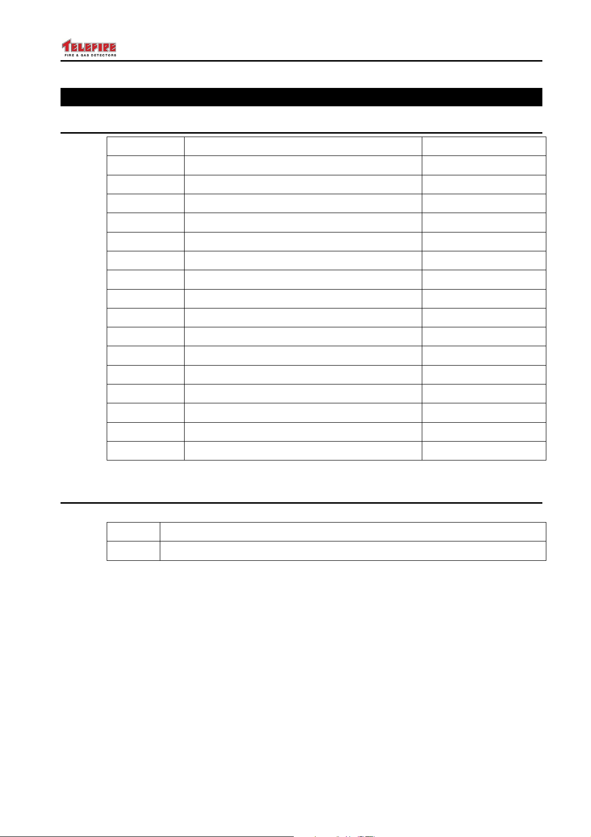
4.1 Abbreviations:
Abbreviation Meaning Remarks
CP Control Panel
ECD Electrical Automatic Control and Delay Device
TB Terminal Block
MCP Manual Call Point
PB Push Button
PC Personal Computer
PS Power Supply
PW Password
M Minute
# (Number)
FWRE Fault Warning Routing Equipment Fault Dialer
FARE Fire alarm Routing Equipment Alarm Dialer
AC Alternating Current
AH Ampere Hours
RH Relative Humidity
PTC Positive Temperature Coefficient (FUSE)
4.2 Terms and Definitions
TERM MEANING
Event A change which is detectable by the ECD and causes a response
– Page 8 of 8 –
Page 17
TSA-1000
© 2008 – 2012 Telefire Fire & Gas Detectors Ltd Revision 1.12 האיגש!אצמנ אל הינפהה רוקמ .
5 Safety
Note
i
i
5.1 Grounding and Mains Supply Connection
i
Do not install commission, operate, or maintain this product before fully
reading and thoroughly understanding this manual.
Note
Whenever possible, disconnect all power sources (Line AND Battery) from
the product before performing any work on the ECD.
Note
All installation, maintenance work and connecting/Disconnecting of the ECD
to power sources shall be performed according to applicable international,
national, regional and local codes and regulations, and the specific
instructions by the manufacturer.
i
i
i
Note
All maintenance work should only be performed by trained, qualified and
certified personnel only.
Personnel that work on this equipment must fully read and comprehend this
manual.
Note
Connection/Disconnection of the control panel to the mains should be
performed by QUALIFIED AND AUTHORIZED personnel ONLY
Note
Disconnect all mains power wires (Line AND Neutral) to the circuit to which
you intent to connect the control panel, before actually connecting the mains
input power cable to the ECD.
Verify that the ECD enclosure is properly grounded before applying power
– Page 9 of 9 –
Page 18

TSA-1000
© 2008 – 2012 Telefire Fire & Gas Detectors Ltd Revision 1.12 האיגש!אצמנ אל הינפהה רוקמ .
5.2 Batteries Handling and Safety
Note
i
Refer to the batteries’ manufacturer literature for full information.
The following information supplements and highlights manufacturer’s information.
WHEN HANDLING BATTERIES, OBSERVE THE MANUFACTURER’S
RECOMMENDATIONS REGARDING CLOTHING AND PROTECTIVE GEAR
Use two 12V 5 AH sealed Lead Acid batteries, such as Yuasa NP5-12 or equivalent,
connected in series.
Use the supplied wires to connect to the batteries, and to connect two batteries in series.
Since the batteries used are maintenance free, and the ECD automatically controls the
battery charging, discharge and test, no SPECIAL maintenance is required.
OBSERVE THE FOLLOWING:
Connect the battery to the ECD main board battery terminal block using the supplied
wires. Observe polarity.
Keep the batteries clean and dry
Keep the area well ventilated
Smoking, fire or sparks ARE NOT ALLOWED near batteries.
When working on batteries, DISCONNECT THE BATTERIES AND ALL OTHER
POWER SOURCES
Batteries require special care and safety precautions.
Note
i
Follow the manufacturer’s instructions for cleaning the batteries and the enclosure, if
necessary
Dispose of batteries properly
Do not short-circuit, puncture, crush, or dispose of batteries in fire.
Do not connect batteries to makeshift chargers or power supply.
Do not expose the batteries or its terminals to mechanical stress
Handling of materials that leak from the batteries should be done by qualified personnel
using the appropriate protective gear, materials, and procedures.
If the ECD indicates a battery fault, check the wiring.
If necessary, replace the batteries
If batteries show any signs of swelling, rupture, fluid leakage, emission of
gases or fluids, heating or discoloration, or accumulation of corrosion
products near the terminals, OR YOU HEAR A HISSING SOUND, disconnect
the batteries and replace with a new pair of the appropriate type.
– Page 10 of 10 –
Page 19
TSA-1000
© 2008 – 2012 Telefire Fire & Gas Detectors Ltd Revision 1.12 האיגש!אצמנ אל הינפהה רוקמ .
6 Access Levels
The control panel provides protection from unauthorized access of certain functions by
various access levels.
The TSA-1000 includes electronic and mechanical mechanisms that enact 4 access
levels, as per EN 54-02 Annex A:
• Access level 1 – not limited, immediate access by operator
• Access level 2 (operator) – protected by an operator password. Provides all of
access level 1 functions and allows access to additional functions that are
performed on a regular basis by the system’s operator.
Note
i
To avoid multiple PW key punching, there is a 3 minutes period after the
operator's PW has been entered, when the PW remains valid and effective,
which enables the operator to perform several tasks continuously without
entering the PW separately for each action.
(Since. In the password delay, the reentering of level 2 PW is not required,
level 2 access appears to be level 1 access, and level 3 appears to be level 2
access)
Access level 3 (programmer & installer) – protected by a programmer
password (different from the operator's password!)or a mechanical key.
Provides all of access to level 1 and 2 functions and allows access to
additional functions such as programming, and access for functions
performed during installation.
Note
i
• Access level 4 (manufacturer) – Only accessible using a dedicated PC SW tool or a
The mechanically controlled access elements are detailed below.
The ECD enclosure has a door/front-panel with a mechanical lock. A detachable key is
required to open the lock, which requires a positive and deliberate action and prevents
accidental and non authorized access. Hence the access level to the batteries and AC
power lines and the field wiring connections is 3/4.
Two switches are located on the front panel. A Manual &Automatic/Manual Only keyswitch and a Manual Activation Push Button switch.
Access levels 2 and 3 have different passwords. This is not correlated to the
number of times the password has to be keyed in to access a certain menu.
Some sub-menus which are accessible at level 3, require that the level 3
(programmer) password be entered in a single menu, while others (for
additional safety) require the level 3 password to be entered in to different
menus
mechanical key.
– Page 11 of 11 –
Page 20

TSA-1000
© 2008 – 2012 Telefire Fire & Gas Detectors Ltd Revision 1.12 האיגש!אצמנ אל הינפהה רוקמ .
7 Technical Specifications
7.1 Main Elements, Basic Unit
The TSA-1000 comprises the following major elements:
• A metal enclosure with a hinged and mechanically lockable door. The door also
serves as the front panel
• PS40W Power Supply / Charger
• TSA-1000 Main Board (1 change polarity output, 5 level activation outputs, 4 inputs,
3 relays)
• TSA-1000D Display board
• Flat Cable for connecting the Main Board to the Display board
• Two 12V 5AH batteries (Connected in series).
• Link wire for connecting the two batteries in series
• Two (single) wires for connecting the batteries to the PS "BATTERY" TBs.
• Flat Cable for connecting the PS to the main Board
• Two 4 wire cables, for connecting the MB to the TSA-1000E8 card.
• Clamp On ferrite on AC input cable
• Clamp On ferrite on flat cable from MB to the display board.
7.2 Expansion Modules
The TSA-1000 basic unit functionality can be extended using the following expansion
boards/modules;
• TSA-1000E4 expansion board (4 inputs)
• TSA-1000E8 expansion board (8 inputs)
• TSA-1000EM083 expansion board (8 Open Collector outputs, 3 relays)
Prerequisite: TSA-1000E4 or TSA-1000E8
• TSA-1000EM422 expansion board (4 inputs, 2 programmable outputs, 3
programmable relays)
Prerequisite: TSA-1000E4 or TSA-1000E8
• TSA-1000C Communication module
7.3 I/O Functions of the Different Expansion Boards/Modules
The MB inputs and the expansion modules inputs are of the same design and have
identical electrical characteristics. So are the Relays, Level Activation outputs, Open
Collector outputs, etc.
The alarm dialer output is a level activation output with educed current capability (0.6A
instead of 0.8A).
7.4 Relays
Relays' contacts are not monitored, supervised or protected.
Connect external protective circuitry to the relays' contacts.
Relays are intended for same room connection only.
– Page 12 of 12 –
Page 21

TSA-1000
© 2008 – 2012 Telefire Fire & Gas Detectors Ltd Revision 1.12 האיגש!אצמנ אל הינפהה רוקמ .
7.5 TSA-1000C Communication Expansion module
The TSA-1000C communication expansion provides the following communication and
networking capabilities;
RS-232 ......................................................................... 1 – for PC connection
RS-485 ......................................................................... 2 – remote panels and
..................................................................................... ……..networking
FWRE (Fault Warning Routing Equipment) output........ 1 – (Fault Dialer)
Remote Panel Annunciators ......................................... Up to 4 RM-1000 panels through
…………………………………………………………..the RS-485 connector
Note! The TSA-1000C communication module contains the FWRE, or Fault Dialer,
of the TSA-1000.
– Page 13 of 13 –
Page 22
TSA-1000
© 2008 – 2012 Telefire Fire & Gas Detectors Ltd Revision 1.12 April 2012
7.6 Table of Technical Specifications, TSA-1000
ITEM RATING REMARKS COMMUNICATION
PARAMETERS
MECHANICAL
Dimensions (W / H / D)
Weight (excluding batteries)
370 / 290 / 90 mm
TSA-1000E4 or TSA-1000E8 3,470 gr.
TSA-1000Ex and TSA-1000EM083 3,600 gr
TSA-1000Ex and TSA-1000EM422 3,600 gr.
ENVIRONMENTAL
Operating Temperature range
IP rating
-5°C ÷ +40°C, Max RH 95% Non condensing
30
Environmental class A
POWER RATINGS
Mains Supply 230VAC+10% -15%, 50Hz , 0.6A TB line connection
Mains Supply Fuse 3.15A 250VAC 5x20mm glass Fast Blow Bussman S500-3.15-R or equiv.
Power Supply output rating, 27.5V±0.3V, 8 pin header
Total output current 1.5A electronic current limit (including charge current),
5V output rating 5V, ±0.2V 0.5A electronic current limit
Max Ripple Voltage 28V & Charger out: 320mV, 5V out: 80 mV
– Page 14 of 14 –
Page 23
TSA-1000
© 2008 – 2012 Telefire Fire & Gas Detectors Ltd Revision 1.12 April 2012
ITEM RATING REMARKS COMMUNICATION
PARAMETERS
Battery Type Two 12V 5AH connected in series Yuasa NP 12-5 or equivalent
Battery Charge Voltage 27.3V±0.2V Modulated DC
Battery Charge Current 0.3A max. Electronically limited
Battery Fuse 3A PTC
Current consumption from battery Quiescent condition, buzzer ON Panel Only
Basic configuration 70 mA
with TSA-1000E4 110 mA
with TSA-1000E8 120 mA
with TSA-1000E4 and TSA-1000-
115 mA
EM083
with TSA-1000E8 and TSA-1000-
125 mA
EM083
with TSA-1000E8 and TSA-1000-
145 mA
EM422
Maximum Current Consumption two zones in alarm, panel only
Basic configuration 150 m A
with TSA-1000E4 180 mA
with TSA-1000E8 190 m A
– Page 15 of 15 –
Page 24
TSA-1000
© 2008 – 2012 Telefire Fire & Gas Detectors Ltd Revision 1.12 April 2012
ITEM RATING REMARKS COMMUNICATION
PARAMETERS
with TSA-1000E4 and TSA-1000-
200 mA
EM083
with TSA-1000E8 and TSA-1000-
210 mA
EM083
with TSA-1000E8 and TSA-1000-
250 mA
EM422
Max Current from Batteries 3A Protected by a PTC
Battery voltage range 20.4V DC min to 27.5V DC max
Max (single) battery size to 9.5 (W) by 7 (D) by 12.5 (H) cm each
MB INTERFACES
MB Relays
Relay 1, Programmable 48V DC, 1.5A, not monitored Dry contact SPDT
Relay 2, Programmable 48V DC, 1.5A, not monitored Dry contact SPDT
Relay 3, Programmable 48V DC, 1.5A, not monitored Dry contact SPDT NC when unpowered
MB OUTPUTS MB outputs are monitored
Outputs EOL 3.9 K ±5% Only required for MB outputs
MB out 1 Change Polarity, 1.4A Current limited OFF-6V. ON +24V,
MB out 2 Level Act. 24V DC, 0.8A, Current limited, Programmable, Silenceable Modulated DC
– Page 16 of 16 –
Change Polarity DC
Programmable, Silenceable
Page 25
TSA-1000
© 2008 – 2012 Telefire Fire & Gas Detectors Ltd Revision 1.12 April 2012
ITEM RATING REMARKS COMMUNICATION
PARAMETERS
MB out 3 Level Act. 24V DC, 0.8A, Current limited, Programmable, Silenceable Modulated DC
MB out 4 Level Act. 24V DC, 0.8A, Current limited, Programmable, Silenceable Modulated DC
Outputs 1-4 programmable Delay 0 – 55 seconds
configured separately for each
output
MB output Fire Alarm Dialer Level Act. 24V DC, 0.6A, Current limited Modulated DC
MB output Alarm Sounder (Horn) Level Act. 24V DC, 0.8A, Current limited Silenceable Modulated DC
+24V output 24 Nominal 1.4A electronic current limit Not affected by reset
Resettable +24V output 24 Nominal 1.4A electronic current limit Not powered during Reset Switched DC
MB INPUTS MB inputs are monitored
Input alarm resistance range 70-630Ω ±5%, Nominal alarm resistor 200 Ω
Input Normal Range 700Ω – 6.5kΩ ±5%Nominal EOL 3.9KΩ ±5%
Input Short Threshold 0-40 Ω±5%,
Input Open threshold 7.5kΩ to ∞
Inputs 1-4 See above for inputs characteristics Detectors
E4 (inputs) Expansion card
Input 1 See MB above for inputs characteristics E4 card Inputs are monitored
Input 2
Input 3
Input 4
– Page 17 of 17 –
Page 26
TSA-1000
© 2008 – 2012 Telefire Fire & Gas Detectors Ltd Revision 1.12 April 2012
ITEM RATING REMARKS COMMUNICATION
PARAMETERS
E8 (inputs) Expansion card
Input 1 See MB inputs for inputs characteristics E8 card Inputs are monitored
Input 2
Input 3
Input 4
Input 5
Input 6
Input 7
Input 8 .
EM083 (outputs) expansion card
EM083 OPEN COLLECTOR
Prerequisite: E4 or E8 module
OUTPUTS
OC 1 24V Nominal, 50mA OC outputs are not monitored
OC 2 24V Nominal, 50mA
OC 3 24V Nominal, 50mA
OC 4 24V Nominal, 50mA
OC 5 24V Nominal, 50mA
OC 6 24V Nominal, 50mA
OC 7 24V Nominal, 50mA
– Page 18 of 18 –
Page 27
TSA-1000
© 2008 – 2012 Telefire Fire & Gas Detectors Ltd Revision 1.12 April 2012
ITEM RATING REMARKS COMMUNICATION
PARAMETERS
OC 8 24V Nominal, 50mA
EM083 RELAYS
Relay 1 See MB relays for relays characteristics
Relay 2
Relay 3
EM422 Expansion Card
Prerequisite: E4 or E8 module
EM422 Inputs
Input 1 See MB inputs for inputs characteristics
Input 2
Input 3
Input 4
EM422 Outputs
Out 1 Level Act. 24V DC, 0.8A, Current Limited Programmable, Silenceable Modulated DC
Out 2 Level Act. 24V DC, 0.8A , Current Limited Programmable, Silenceable Modulated DC
EM422 Relays
Relay 1 See MB relays for Relays characteristics
Relay 2
– Page 19 of 19 –
Page 28
TSA-1000
© 2008 – 2012 Telefire Fire & Gas Detectors Ltd Revision 1.12 April 2012
ITEM RATING REMARKS COMMUNICATION
PARAMETERS
TSA-1000C – Communication
Module
GENERAL
Input nominal quiescent voltage,
current
Terminal block wire capacity 12-18 AWG
Max number of detectors per zone 32
Number of detection zones Dependant on HW configuration
Total number of detectors Dependant on HW configuration
CABLING SEE "INSTALLATION"
Table 1 Technical Specifications
RS-232 1
RS-485 2
FWRE 1
18.5v, 5.0mA Current Limit
For PC connection
Remote panels and networking
Fault dialer
RS-232
RS485
Modulated DC
Note
i
– Page 20 of 20 –
Specifications are subject to change without prior notice.
Page 29

TSA-1000
© 2008 – 2012 Telefire Fire & Gas Detectors Ltd Revision 1.12 האיגש !אצמנ אל הינפהה רוקמ. 2
7.7 Default Ports Allocation and Configuration
By default, all the TSA-1000 inputs are detector zones inputs, and all outputs (except
horn and alarm dialer) are general outputs.
To modify these settings the TSA-1000 must be programmed.
– Page 21 of 21 –
Page 30
TSA-1000
© 2008 – 2012 Telefire Fire & Gas Detectors Ltd Revision 1.12 האיגש !אצמנ אל הינפהה רוקמ. 2
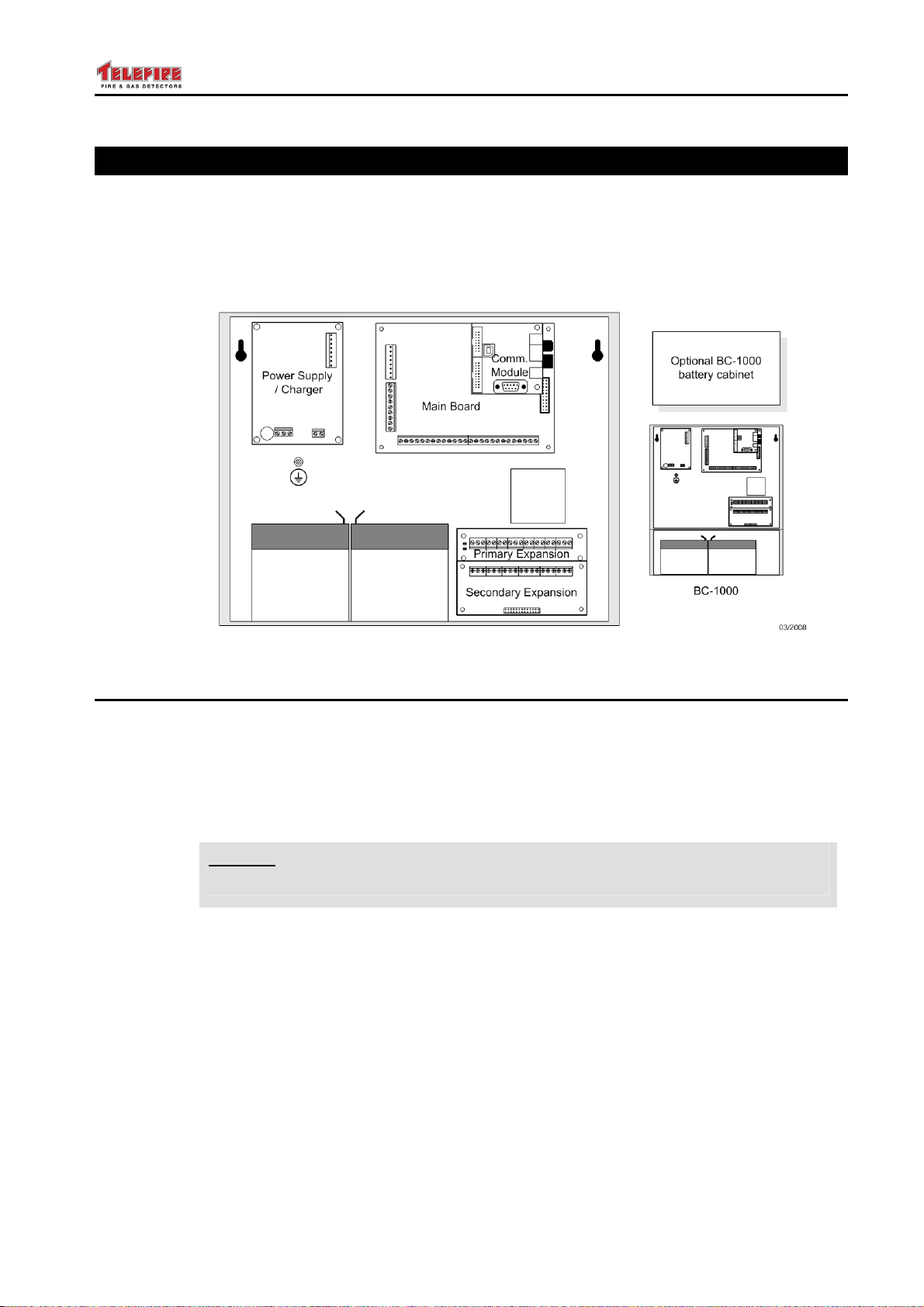
8 TSA-1000 Control Panel Assembly
The TSA-1000 contains the power supply, the main board, optional expansion modules,
and an optional communication module.
The wiring openings were designed to allow a bottom or top mains input and a bottom,
top, or back low-voltage connection, to the installer’s convenience.
An optional BC-1000 battery compartment can be attached below the TSA-1000.
Figure 2 Module location
8.1 Power Supply, Charger and Batteries
The TSA-1000 is powered by the PS40_W Power Supply/Charger, which is located at
the top left corner of the enclosure/.
The PS40_W requires 230VAC, +10%, -15%, 50/60Hz.
It is protected by a 5x20 mm, 3.15A glass Fast-Blow fuse, located at the bottom left
corner of the PS_40W (F2).
Note
i
The PS40_W provides 27.5±0.3 V (referred to as the 24V supply rail) for powering the
ECD and for charging the battery, and has a +5V 0.5A output for powering the ECD MB
logic.
Max "24V" supply load current is 1.5A (including the 0.3A charging current)
The maximum battery charging current is 0.3A, electronically limited. The max allowed
load on the battery (when the mains power is disconnected or OFF) is 3A, limited by a
PTC.
Type and rating of batteries;
The ECD requires two 12V, 5AH sealed Lead Acid batteries, connected in series.
(Yuasa NP 5-12 or equivalent)
Replace ONLY with a fuse of the same type, size and rating.
– Page 22 of 22 –
Page 31
TSA-1000
1 3 3
1 3 3
1 3 6 8
1 3 3
© 2008 – 2012 Telefire Fire & Gas Detectors Ltd Revision 1.12 האיגש !אצמנ אל הינפהה רוקמ. 2
8.2 Main Board
The main board is designed to be easy to install and maintain. The connectors are
grouped per type: three programmable relays, four programmable outputs, dialer output,
horn, 24V DC out (both resettable and permanent), and four inputs; connections to the
display / keyboard card and expansion connectors.
8.2.1 Low-Voltage Connections
Zone Connectors Four programmable inputs
Relays; Three programmable dry-contact relays.
Programmable Outputs; Four supervised and programmable 24V outputs. Output 1 is
an enhanced “reversed polarity” output; outputs 2 to 4 are “level activation” outputs.
General Outputs; A supervised horn output, a supervised fire alarm dialer output,
and a 24VDC output to supply power to external devices.
Expansion Connectors; Two connectors for expansion modules, and a connector for
the optional communication module.
8.3 Expansion Modules
The expansion modules make it possible to add input, output and relays through the
control panel, up to a configuration of 16 zones.
The expansion modules series includes:
• TSA-1000-E4 – an expansion module for 4 inputs
• TSA-1000-E8 – an expansion module for 8 inputs
• TSA-1000-EM422 – an expansion module to the TSA-1000-E8 that includes 4
inputs, 2 supervised programmable outputs and 2 programmable relays
(prerequisite: TSA-1000E8)
• TSA-1000-EM083 – an expansion module to the TSA-1000-E8 that includes 8
unsupervised “open collector” outputs (supply of Minus upon activation) and 3
programmable relays (prerequisite: TSA-1000E8 or TSA-1000E4).
• TSA-100C communication module.
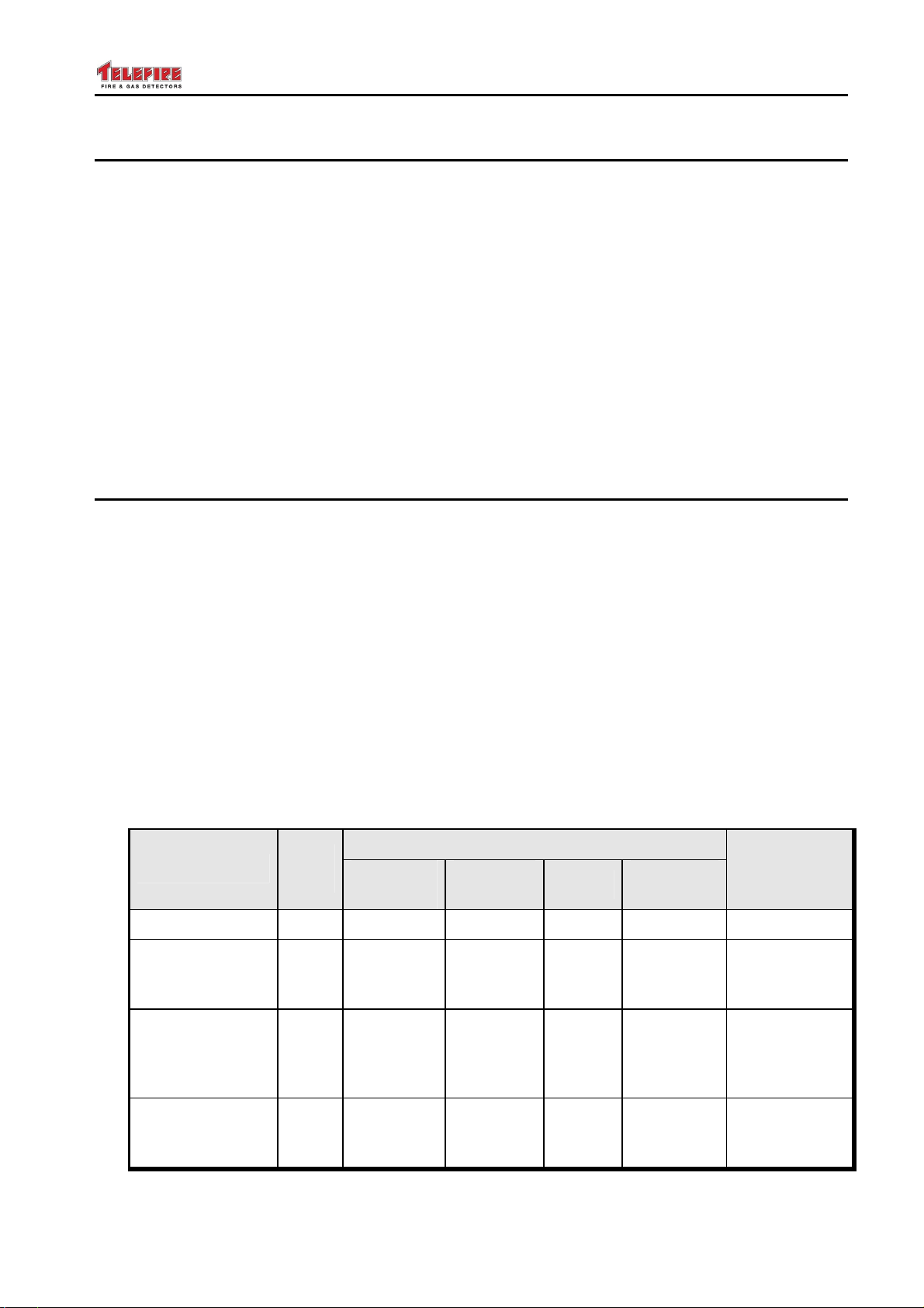
See Table 2 below for a detailed explanation of the various combinations.
Configuration
TSA-1000/4
TSA-1000/8
Base + TSA1000-E4
TSA-1000/8+
Base + TSA1000-E4
+ TSA-1000E083
TSA-1000/12
Base + TSA1000-E8
– Page 23 of 23 –
Prog.
Inputs
Programmable Outputs
Reverse
Polarity
4
8
8
12
Level
Activation
Relays
System
Open
Collector
— C10
— C14
— C11
Configuration
C15
Page 32
TSA-1000
1 3 6 8
1 5 5
© 2008 – 2012 Telefire Fire & Gas Detectors Ltd Revision 1.12 האיגש !אצמנ אל הינפהה רוקמ. 2
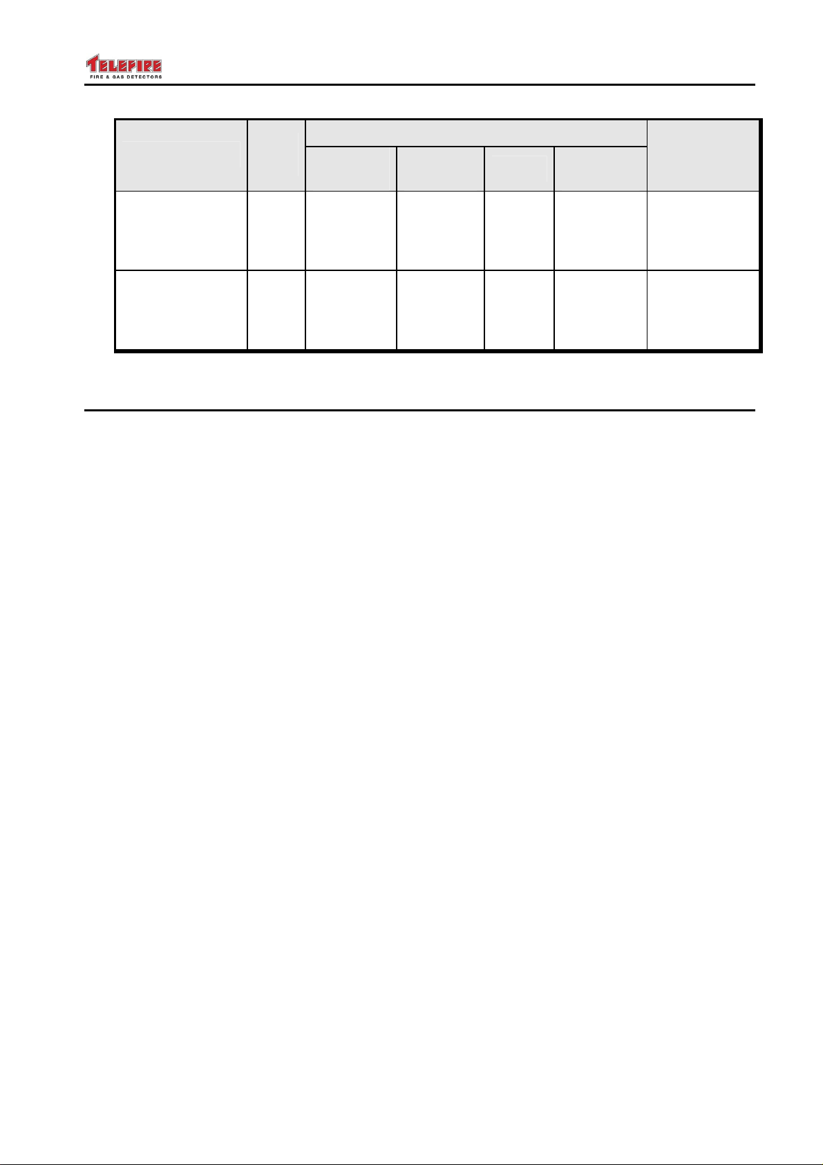
Configuration
TSA-1000/12+
Base + TSA1000-E8
+ TSA-1000E083
TSA-1000/16
Base + TSA1000-E8
+ TSA-1000E422
Table 2 TSA-1000 – number of inputs and outputs of the various configurations
8.4 Front Door
A front door completes and closes the CP box and enacts access level 4 for some
operations, since it needs a tool (screwdriver) for opening. It also serves as a front
panel, as it has a display and a keyboard, which includes separate indicating LEDs,
programming keys, and a 3-digit 7 segments display.
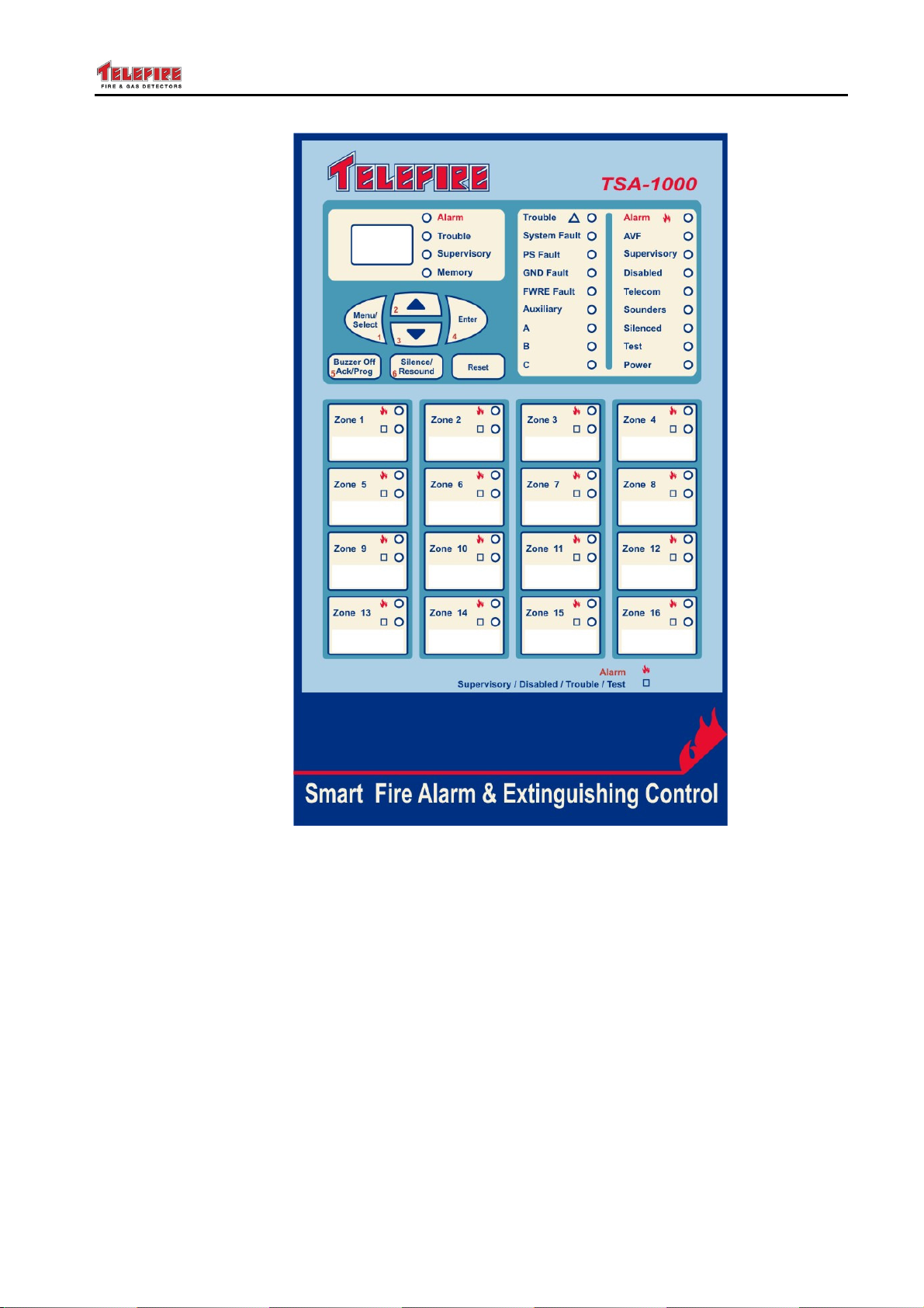
The display and keyboard comprise four main areas:
• General display zone
• Digital display and clarification area
• Keyboard
• Zone Indicators
Prog.
Inputs
12
16
Programmable Outputs
Reverse
Polarity
Level
Activation
Relays
System
Open
Configuration
Collector
C12
— C13
– Page 24 of 24 –
Page 33
TSA-1000
© 2008 – 2012 Telefire Fire & Gas Detectors Ltd Revision 1.12 האיגש !אצמנ אל הינפהה רוקמ. 2
Figure 3 Display and Keyboard
– Page 25 of 25 –
Page 34
TSA-1000
© 2008 – 2012 Telefire Fire & Gas Detectors Ltd Revision 1.12 האיגש !אצמנ אל הינפהה רוקמ. 2
9 User Interface-Display and Keyboard
The front door of the TSA-1000 also serves as the user interface, and contains a display
and a keyboard.
The display has three distinct areas:
A General Display area (distinct, separate LEDs)
Zones indications area (distinct, separate LEDs)
Digital Display area (3 7 segments numeric digits display)
Digital Display indications area (distinct, separate LEDs)
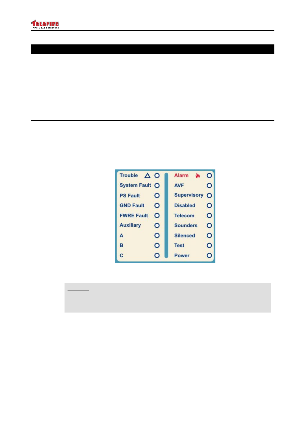
9.1 General Display Area
The general display area is the main display of the TSA-1000.
It is made up of two rows, where each row has 9 LEDs.
The right column provides status information such as Alarm, Power On, Test State, etc.
The left column displays faults of the control panel, A, B, C indicators are reserved for
future use. The General Display Area is shown below, and the function of each LED is
explained.
Figure 4 General Display Area
Note
i
– Page 26 of 26 –
The term "outputs" in the following table refers to any or all outputs, including
Horn output, Fire Dialer output, FWRE output, programmable outputs, or
relays.
Page 35

TSA-1000
© 2008 – 2012 Telefire Fire & Gas Detectors Ltd Revision 1.12 האיגש !אצמנ אל הינפהה רוקמ. 2
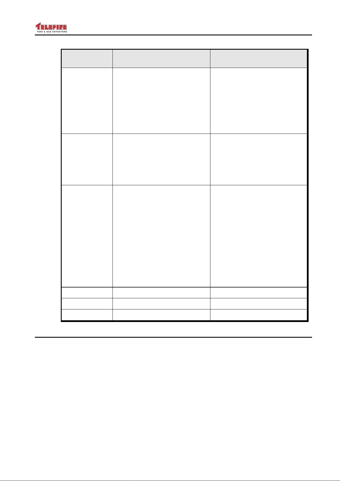
LED Its Color and meaning
(EN 54 / CP 10 version)
Alarm
Red LED. Indicates fire alarm.
The zone in alarm is displayed
on the digital display and is
indicated by the zone’s private
indication LED.
• Off in normal state
• Flashes during alarm until
the control panel is reset
AVF
Yellow LED. Indicates alarm
verification. AVF is also
displayed (V##) on the digital
display.
• Off in normal operation
• Flashes during alarm
verification
Supervisory
Yellow LED. Indicates a
supervisory event.
• Off during normal operation
• The LED flashes as long as
the supervisory event is in
force. Additionally the
zones supervisory LED also
flashes
Its Color and meaning (UL 864
/ IS 1220 version)
Red LED. Indicates fire alarm.
The zone in alarm is displayed
on the digital display and is
indicated by the zone’s private
indication LED.
• Off in normal state
• Flashes during alarm.
Pressing the Acknowledge
key will turn the LED on
until the control panel is
reset
Yellow LED. Indicates alarm
verification. AVF is also
displayed on the digital display.
• Off in normal operation
• Flashes during alarm
verification
Yellow LED. Indicates a
supervisory event.
• Off during normal operation
• The LED flashes as long as
the supervisory event is in
force. Additionally the
zones supervisory LED also
flashes
Disabled
Yellow LED. Indicates a
disabled input or output.
Additional detail is shown on the
digital display.
• Off during normal operation
• On when one of the inputs
or outputs is disabled.
Additional detail is shown
on the digital display. The
LED will stay on until all
inputs and outputs are
enabled.
Yellow LED. Indicates a
disabled input, or output.
Additional detail is shown on the
digital display.
• Off during normal operation
• On when one of the inputs
or outputs is disabled.
Additional detail is shown
on the digital display. The
LED will stay on until all
inputs, and outputs are
enabled.
– Page 27 of 27 –
Page 36

TSA-1000
© 2008 – 2012 Telefire Fire & Gas Detectors Ltd Revision 1.12 האיגש !אצמנ אל הינפהה רוקמ. 2
LED Its Color and meaning
(EN 54 / CP 10 version)
Telecom
Red/Yellow LED. Indicates a
fault event in the dialer line.
Additionally a fault alert marks
this event.
• Off in normal operation
• ON in red during dialing
• Flashes in yellow when
there is a fault event in the
dialer
• Solid yellow when the dialer
is disabled
Sounders
Red/Yellow LED. Indicates a
situation where the horns are
disabled due to a fault in the
horn line or disablement of the
horn output.
• Off during normal operation
• ON in red during horn
activation
• Flashes in Yellow when
there is a fault in the horn
line
Its Color and meaning (UL 864
/ IS 1220 version)
Red/Yellow LED. Indicates a
fault event in the dialer line.
Additionally a fault alert marks
this event.
• Off in normal operation
• ON in red during dialing
• Flashes in yellow when
there is a fault event in the
dialer. Pressing the
Acknowledge key will turn
the LED on until the fault is
resolved
• Solid yellow when the dialer
is disabled
Red/Yellow LED. Indicates a
situation where the horns are
disabled due to a fault in the
horn line or disablement of the
horn output.
• Off during normal operation
• ON in red during horn
activation
• Flashes in Yellow when
there is a fault in the horn
line. Pressing
Acknowledge will turn the
LED ON until resolution of
the problem
• Solid yellow when horn
output is disabled
Silenced
Test
– Page 28 of 28 –
Yellow LED. Indicates silenced
condition.
• Off during normal operation
and during alarm
• Flashes during alarm after
silencing.
Yellow LED. Indicates test
mode.
• Off during normal operation,
• On during Field Test.
Yellow LED. Indicates silenced
condition.
• Off during normal operation
and during alarm
• Flashes during alarm after
silencing.
Yellow LED. Indicates test
mode.
• Off during normal operation,
• On during Field Test.
Page 37

TSA-1000
© 2008 – 2012 Telefire Fire & Gas Detectors Ltd Revision 1.12 האיגש !אצמנ אל הינפהה רוקמ. 2
LED Its Color and meaning
(EN 54 / CP 10 version)
Power
Green LED. Indicates the
presence of AC input or battery.
• Always on in normal
operation
• Flashes when there is no
main power.
Trouble
Yellow LED. Indicates a fault in
the system or one of the devices
that are connected to it.
• Off during normal operation
• Indicates a fault event or
one of the connected
devices – see additional
yellow LEDs and the digital
display for addition display.
Its Color and meaning (UL 864
/ IS 1220 version)
Green LED. Indicates the
presence of input power (AC or
battery).
• Always ON in normal
operation
• Flashes when there is no
main power until
Acknowledge key is
depressed. Additionally
there will be additional
warning in the digital
display. Pressing the
Acknowledge key will turn
the LED off
Yellow LED. Indicates a fault
event or one of the connected
devices – see additional yellow
LEDs and the digital display for
addition display.
• Off during normal operation
• Flashes to indicate a fault
event or one of the
connected devices – see
additional yellow LEDs and
the digital display for
addition display. Pressing
Acknowledge will turn the
LED ON until resolution of
the problem
System Fault
Yellow LED. Indicates a hung
processor.
• Off during normal operation
• ON when the processor
hangs
PS Fault
Yellow LED. Indicates a power
fault (loss of AC power;
Disconnected battery; Weak
battery)
• Off during normal operation
• ON when there is a power
supply fault
– Page 29 of 29 –
Yellow LED. Indicates a hung
processor.
• Off during normal operation
• ON when the processor
hangs
Yellow LED. Indicates a power
fault (loss of AC power;
Disconnected battery; Weak
battery)
• Off during normal operation
• Flashes to indicate a
ground fault. Pressing
Acknowledge will turn the
LED ON until resolution of
the problem
Page 38
TSA-1000
© 2008 – 2012 Telefire Fire & Gas Detectors Ltd Revision 1.12 האיגש !אצמנ אל הינפהה רוקמ. 2
LED Its Color and meaning
(EN 54 / CP 10 version)
Ground Fault
Yellow LED. Indicates a ground
leak.
• Off during normal operation
• ON indicate a ground fault.
Pressing Acknowledge will
turn the LED ON until
resolution of the problem
FWRE Fault
Yellow LED. Indicates a Fault
Warning Device Fault.
• Off during normal operation
• ON during a fault in the
FWRE equipment.
Auxiliary
Yellow LED. Indicates a fault in
an auxiliary device. Additional
detail is shown on the digital
display.
• Off during normal operation
• Flashes upon a fault event
in any output device (other
than Horn and outputs
configured as "General,
Silenced")
Its Color and meaning (UL 864
/ IS 1220 version)
Yellow LED. Indicates a ground
leak.
• Off during normal operation
• Flashes to indicate a
ground fault. Pressing
Acknowledge will turn the
LED ON until resolution of
the problem
Yellow LED. Indicates a Fault
Warning Routing Equipment
Fault.
• Off during normal operation
• ON during a fault in the
FWRE equipment.
Yellow LED. Indicates a fault in
an auxiliary device. Additional
detail is shown on the digital
display.
• Off during normal operation
• Flashes on upon a fault
event in any output device
(other than Horn and
outputs configured as
"General, Silenced").
Pressing Acknowledge will
turn the LED ON until
resolution of the problem
A
B
C
Reserved for future use Reserved for future use
Reserved for future use Reserved for future use
Reserved for future use Reserved for future use
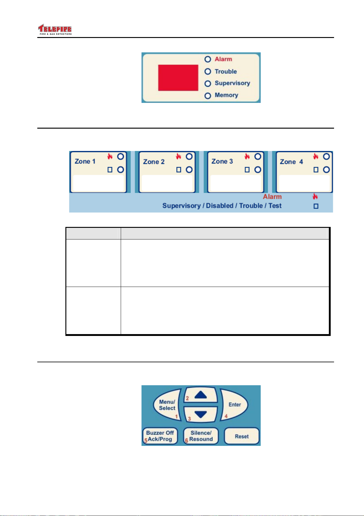
9.2 Digital Display and Digital Display Indicators
The digital display includes three 7-segments digits and a group of 4 discreet separate
LEDs to its right. These LEDs detail and clarify the information provided by the digital
display.
A More Events LED indicates that there are additional events other than the one shown
on the display currently, which can be accessed using the keyboard.
The display module allows a detailed display of work states, faults, programming, etc in
a clear and detailed way to the operator and the technician.
In normal condition, the digital display scrolls the figure 8 from left to right.
– Page 30 of 30 –
Page 39
TSA-1000
© 2008 – 2012 Telefire Fire & Gas Detectors Ltd Revision 1.12 האיגש !אצמנ אל הינפהה רוקמ. 2
Figure 5 Digital Display and Digital Display Indicators
9.3 Zone Indicators
Each zone has 2 LEDs in the zone indication area that indicates the alarm and fault in
that zone.
Figure 6 Zone Indicators
LED Its Color and meaning
Alarm
Fault /
Supervisory /
Disabled / Test
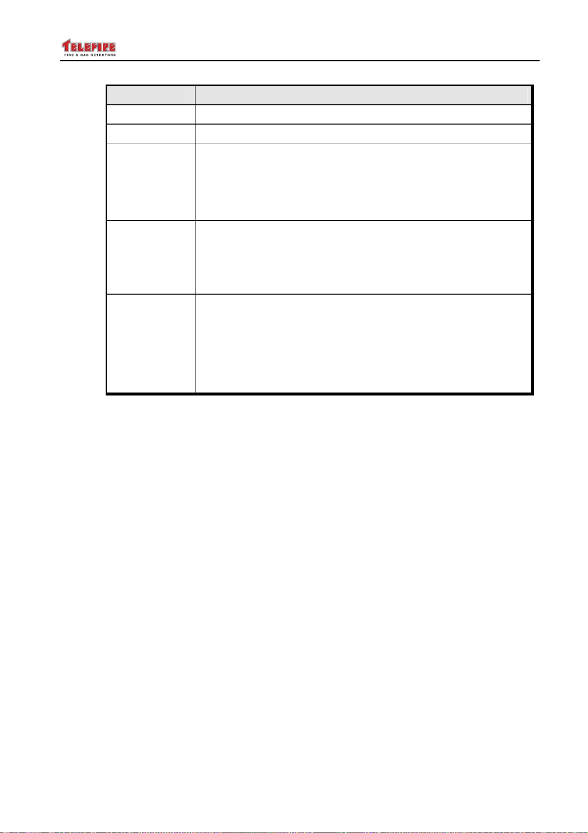
9.4 Keyboard
The keyboard includes 7 keys. The table below shows the function during daily
operation.
Red LED. Indicates that the zone is in alarm.
• Off during normal operation
• Flashes when the zone is in alarm until pressing the
Acknowledge key. Pressing the Acknowledge key will stop
the LED flashing, and turn it on until the control panel is reset.
Yellow LED. Indicates that the zone is in alarm.
• Off during normal operation
• Flashes when the zone is in fault until pressing the
Acknowledge key. Pressing the Acknowledge key will stop
the LED flashing, and turn it on until fault resolution.
Figure 7 Keyboard
– Page 31 of 31 –
Page 40
TSA-1000
© 2008 – 2012 Telefire Fire & Gas Detectors Ltd Revision 1.12 האיגש !אצמנ אל הינפהה רוקמ. 2
Key Function
Menu
Arrows
Buzzer Off /
Ack / Prog
Silence /
Resound
Reset
Enter Menu
Paging through memory
• Is used for silencing the internal alarm buzzer and fault buzzer
in the control panel
• Acknowledges new event. Pressing this key will stop the LED
flashing (indicating new events) and turn the LED ON
• Used for computer printing
• Used for silencing the alarm horns. Devices connected to the
Horn output will be silenced. Devices connected to a
programmed alarm output will be silenced if the output is
defined as silenceable.
• An additional long press will re-activate the output
• Is used to reset alarms and return the system to normal
operations after an alarm. All outputs in the control panel and
inputs to the system are returned to normal operation. The
digital display will show the figure "8" moving from left to right.
The system will return to alarm or fault state during additional
events
• Is used for exiting the menu.
– Page 32 of 32 –
Page 41

TSA-1000
© 2008 – 2012 Telefire Fire & Gas Detectors Ltd Revision 1.12 האיגש !אצמנ אל הינפהה רוקמ. 2
10 Work States
During an alarm, fault or supervisory event on the system, the event is clearly shown by
dedicated LEDs that are labeled Fire Alarm, Fault, and Supervisory, respectively. A
detailed explanation in the digital display will include all the details necessary for
troubleshooting the event and proper resolution.
Fire alarms, fault conditions, and supervisory conditions are defined as events. When
two events occur at the same time, the first event will be shown (preference to an alarm)
and at the same time the Memory LED will be turned on to indicated additional events in
the system.
Fire alarms have a higher priority than fault events and are shown first.
To see the events in the order they occur, use the up and down arrow keys.
10.1 Normal State
Normal state is a state where no alarm or fault event and all of the inputs and outputs
are enabled. In this state, the green power LED is turned on and the digital display
moves the figure 8 from left to right.
10.2 Alarm State
10.2.1 Alarm Verification
The alarm verification feature allows the control alarm to ignore momentarily false
alarms that may cause a nuisance.
When a zone is programmed for alarm verification, the control panel resets the zone in
alarm, waits for 0 to 55 seconds (depends on individual zone programming) and
rechecks whether the same zone is still in alarm. During that time, the control panel will
enter alarm state when receiving an alarm from the same or another zone.
During alarm verification time, the control panel will enter alarm state immediately in
case that there is another alarm indication even if that zone is programmed as alarm
verification.
In case only one alarm triggered the alarm verification clock, during and up to 120
seconds, no additional alarm is received, the clock will be reset and the control panel will
be back in normal mode.
10.2.2 Alarm Operations
During an alarm in one of the detection zones, the control panel performs the following
operations
• Indicating the alarm zone in the digital display
• Turning on the general alarm LED in the digital display and clarification area and the
private alarm zone in the zoning alarm
• Displaying the alarm in the remote panel RM-1000 if connected
• Logging an event in alarm history
• Activating the horn output
• Activating dialer output
• Activating internal buzzer
• Activating relays that were defined as alarm relays (default RL1 and RL2)
10.2.3 Acknowledge / Buzzer-Off Operation
• Silences the internal buzzer
– Page 33 of 33 –
Page 42

TSA-1000
© 2008 – 2012 Telefire Fire & Gas Detectors Ltd Revision 1.12 האיגש !אצמנ אל הינפהה רוקמ. 2
UL 864
UL Models
For UL models, pressing the Acknowledge key will stop the flashing of the
LEDs in the general alarm area, in the digital display and clarification area
and the private LEDs in the zones and turn them ON.
10.2.4 Silence Operation
Pressing the Silence key performs the following actions
• Stops the action of the horn output
• Stops the action of the internal buzzer
• Stops the alarm relay if it was programmed as silenceable
• Stops outputs that were programmed as silenceable
10.2.5 Action during a Second Alarm (Two Zones in Alarm at the
Same Time)
When receiving a second alarm, (i.e., two zones alarms at the same time), the control
panel perform the following operations
• Reactivation of all silenced output
• Turning on the memory LED
• Activating outputs that were programmed to activate upon an alarm from these
zones
10.2.6 Resetting an Alarm
Resetting an alarm can be done by pressing the Reset key.
10.3 Fault State
A fault in the system will be shown indicated in the system by a flashing yellow LED in
addition to the fault code in the digital display.
10.3.1 Actions Performed During Fault
When receiving a fault event at the control panel, the control panel will perform the
following operations
• Indicating the fault code in the display
• Turning on the general fault LED
• The fault LED in the digital clarification area and the private fault LED in the zoning
fault
• Activating the internal buzzer in the control panel
• Logging an event in fault history
• Activating relays that were defined fault relays (default RL3)
10.3.2 Acknowledge / Buzzer off Operation
• Silencing the internal buzzer
• Stopping the flashing of the LEDs in the general alarm area, in the digital display
and clarification area and the private LEDs in the zones and turning them ON (UL
version only)
10.4 Supervisory State
The TSA-1000 has a supervisory function that conforms to UL and EN standards.
– Page 34 of 34 –
Page 43

TSA-1000
© 2008 – 2012 Telefire Fire & Gas Detectors Ltd Revision 1.12 האיגש !אצמנ אל הינפהה רוקמ. 2
In certain cases, there is a need to activate an output following a fault such as indication
of low pressure in an extinguishing cylinder, closed sprinkler valve, etc.
The supervisory function answers these need and allows monitoring switch conditions
and reaction according to the state were using the fire alarm infrastructure.
Supervisory fault does not latch – at the end of the event, the system goes back to
normal state without intervention.
10.4.1 Actions Performed During Supervisory Events
A supervisory event will cause the following events in the control panel
• Turning on the supervisory LED, the supervisory LED in the digital display and
clarification area and the private fault LEDs in the supervisory state
• Indicating the fault event in the RM-1000 remote panel if connected
• Activating fault buzzer
• A logging of the event in the fault history
• Activating supervisory outputs that were belong to the activated fault supervisory
zone, if defined
• Activating supervisory relays, if defined
10.4.2 Acknowledge / Buzzer off Operation
• Silencing the internal buzzer
• Stopping the flashing of the LEDs in the general alarm area, in the digital display
and clarification area and the private LEDs in the zones and turning switching them
on continuously
UL 864
UL Models
For UL models, pressing the Acknowledge key stops the flashing of the
LEDs in the general alarm area, in the digital display and clarification area
and the private LEDs in the zones and switching them on continuously.
10.5 Disablement State
Sometimes there is temporarily a need to disable a particular input, output, or relay.
The control panel will ignore alarms from disabled zones and will not activate disabled
outputs or relays.
When one of the zones or output is disable, the disabled LED is turned on to indicate
this status.
10.6 Test State
Test states allow testing the control panel without activating outputs. This state is
indicated by – – – in the digital display and in the LEDs test clarification area
See page 65 for additional information about Field Test.
– Page 35 of 35 –
Page 44
TSA-1000
© 2008 – 2012 Telefire Fire & Gas Detectors Ltd Revision 1.12 האיגש !אצמנ אל הינפהה רוקמ. 2
11 Installation
11.1 Pre-Installation Planning
Planning of quantity and location of detectors, push buttons, notification appliances and
extinguishing devices shall be done according to the local codes and regulations and in
accordance to the planning consultant's requirements.
11.1.1 Capacity Planning
Ensure that the total number of input initiating devices does not exceed local regulations
of the number of initiating devices per zone, area or other limitations. Ensure that the
number of zones satisfy the requirements of the consulting planner, use expansion
modules as necessary.
You can connect up to 5 sounders, beacons, or sounders-beacons to any programmable
output and the horn output.
Note
i
Do not connect devices that should be supervised to the TSA-1000-EM083.
EN 54
CP 10
EN 54 Requirement
• EN 54 allows up to 32 devices per zone. This limitation may differ for
different countries and local regulation– check your specific limitation
based on your local standards and regulations.
• According to EN 54-2 limitation, do not connect more than 512 initiating
devices to a single TSA-1000 control panel.
CP 10 Requirement
CP-10 allows up to 20 smoke detectors or up to 40 heat detectors per zone.
The TSA-1000 was tested and certified to CP-10 based on these limitations.
11.1.2 Calculating Current Requirement and Battery Capacity
For every control panel calculate the total current consumption of all devices such as
sounder, beacons, extinguishing cylinders, automatic dialer etc. Ensure that the total
current consumption does not exceed 1.4A.
The batteries are chargeable, sealed lead acid batteries, in total voltage of 24 volts (two
12 volt batteries in series) and capacity of up to 7.2AH.
Battery capacity shall be calculated according to the loads and applicable regulations.
11.1.3 Cabling Planning – Initiating Device Circuit (IDC – Zones)
Use a 2-wire cable, 12 – 18 AWG (0.8 to 3.3 mm2) for IDC (zone) connections.
Wire Type Cross-Section (mm2) Maximum IDC Length
18 AWG 0.82 mm
16 AWG 1.31 mm
14 AWG 2.08 mm
12 AWG 3.31 mm
Table 3 IDC cable selection
– Page 36 of 36 –
1,200 m
1,900 m
3,000 m
4,800 m
3,940 ft
6,230 ft
9,840 ft
15,750 ft
Page 45

TSA-1000
© 2008 – 2012 Telefire Fire & Gas Detectors Ltd Revision 1.12 האיגש !אצמנ אל הינפהה רוקמ. 2
11.1.4 Cabling Planning – Activation Lines and 24Vdc Out
Use a 2-wire cable, 12 – 18 AWG (0.8 to 3.3 mm2) for Activation Lines and 24Vdc Out
connections.
The length of activation lines and 24Vdc out cabling depends on the required current
and cable size. Ensure that the maximum voltage drop to the end of the line at full load
does not exceed 3V and will leave the last device the minimal operating voltage as per
the manufacturer's specification.
11.1.5 Cabling Planning – Shielded Cables
It is highly recommended to avoid outdoor wiring due to the increased susceptibility to
lightning strikes. Overhead cables running between buildings or on roofs should be
shielded. The shield should be connected to the ground by using the Master Ground
Terminal in the control panel. Grounding should not be connected to any other points.
Ensure continuous grounding by soldering.
Note
i
When installing a system at a site adjacent to high power cables, heavy
industrial machinery, or any kind of high electromagnetic fields, shielded
cables should be used and an EPI-3000 module should be connected to each
TSA-1000.
11.1.6 Cabling Planning – RS-485 to RM-1000 Remote Panels and
Control Panel Networks
RM-1000 remote annunciators connected to the control panel to a 4 wire cable. A pair
of RS 485 data cable from the control panel and a pair of 24 volts DC from the control
panel or an external power supply such as the TPS 34.
Cabling will be done as per the recommendation of RS485 and local fire regulations –
the more stringent of the two. Long distance cables or cables between buildings or
rooftops shall be shielded.
The cabling from the control panel to the remote panels is in linear (bus) topology.
Maximum total cable length is 1,220 m.
11.1.7 Activation Matrices Planning
Plan the activation logic according to the requirements of the consultant.
11.1.8 Extinguishing Device Planning
Size and quantity of extinguishing cylinders shall be calculated by authorized personnel
in accordance to the requirements of the consultant and local regulations.
11.2 Mounting
11.2.1 Environmental Limits
The TSA-1000 is a class A (-5°C to +40°C, RH max 95%) temperature range device.
Its environmental protective level is IP30.
Note
i
– Page 37 of 37 –
See "installation instructions" for information about maintaining the protection
level
Page 46
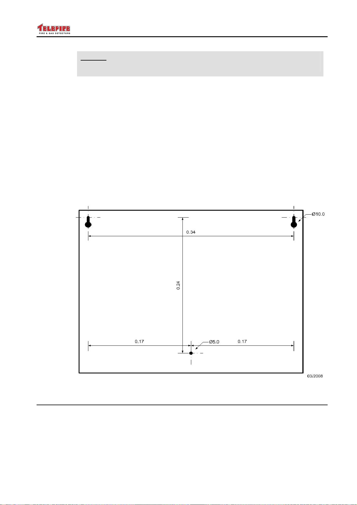
TSA-1000
© 2008 – 2012 Telefire Fire & Gas Detectors Ltd Revision 1.12 האיגש !אצמנ אל הינפהה רוקמ. 2
Note
i
Do not operate the ECD outside the specified limits.
11.2.2 Mounting Recommendations and Instructions
The control panel should be installed in an indoor location, meeting the specified
environmental limits, where it is protected from the elements. Select a location which is
free of smoke, dust or high humidity, and which is distant from sources of electrical
noise, such as high power motors, relays, etc. Avoid locating the control panel in direct
sunlight
Mount the TSA-1000 to a solid wall so it will have comfortable access to connecting the
cables from the input and output devices and maintenance personnel for ongoing
operations and in a location where it is possible to supervise and clearly see the display
and indicators.
The back of the chassis has 2 sliding slots on the top half and the bottom has a hole for
securing the chassis to the wall.
Drill the hole for mounting using the chassis mounting holes drawing below.
Figure 8 Chassis Mounting Holes
11.3 Wiring
11.3.1 Routing Cables into the ECD and Maintaining the Protection
Level
In order to route power and field wiring into the ECD, the appropriate, partially punched
knockouts must be removed.
Use a hammer and a chisel to open and remove the knockout.
– Page 38 of 38 –
Page 47
TSA-1000
© 2008 – 2012 Telefire Fire & Gas Detectors Ltd Revision 1.12 האיגש !אצמנ אל הינפהה רוקמ. 2
Do not remove unnecessary knockouts
Remove burrs and sharp edges, if necessary
Note
i
Insert the cables through the glands before connecting them to the ECD.
Tighten the cover nut to securely clamp the cable or group of field wires.
This serves as a strain relief and as means to meet the IP30 requirements.
i
To maintain the IP30 protection level, use appropriately sized cable glands
such as CABLE GLAND NEMA 4X PG-7 BLACK manufacture by BUD, or
equivalent.
Note
If unused knockouts opening remain, they must be plugged with an
appropriate, secure cover/plug to maintain the required protection level
11.3.2 Wiring Information
The TSA-1000 is supplied in working condition, fully assembled, and with all internal
modules pre-wired. Wiring instructions are only for connecting the system to AC input,
zones, programmable output and general output.
Cable type selection and wiring shall be done according to local regulations.
System connections shall be done when power sources are disconnected.
Changing/installing electric activation modules shall be done after the system is in
quiescence state (push buttons and detectors in normal state).
Characteristic IDC Outputs
Electric Resistance Minimal Very High
Capacitance No Influence No Influence
Inductance Minimal Minimal
Mechanical Strength High High
Table 4 Wiring Characteristics’ influence on System Performance
Warning
!
Disconnect all power supplies, main and batteries before connecting or
disconnecting cables to the control panel.
11.3.3 Mains Power Supply
Connect the control panel’s AC input line to a dedicated circuit breaker that is not shared
by other appliances or equipment. It is recommended that the circuit breaker shall be
labeled “FIRE ALARM”.
The power cable should enter the control panel through either the top left or bottom left
knockout opening and separated from the field wiring Use a plastic bushing that fits the
opening. Connect the Live and Neutral wires to the proper terminal. Connect the
Ground wire directly the panel's chassis using the marked ground screw.
– Page 39 of 39 –
Page 48
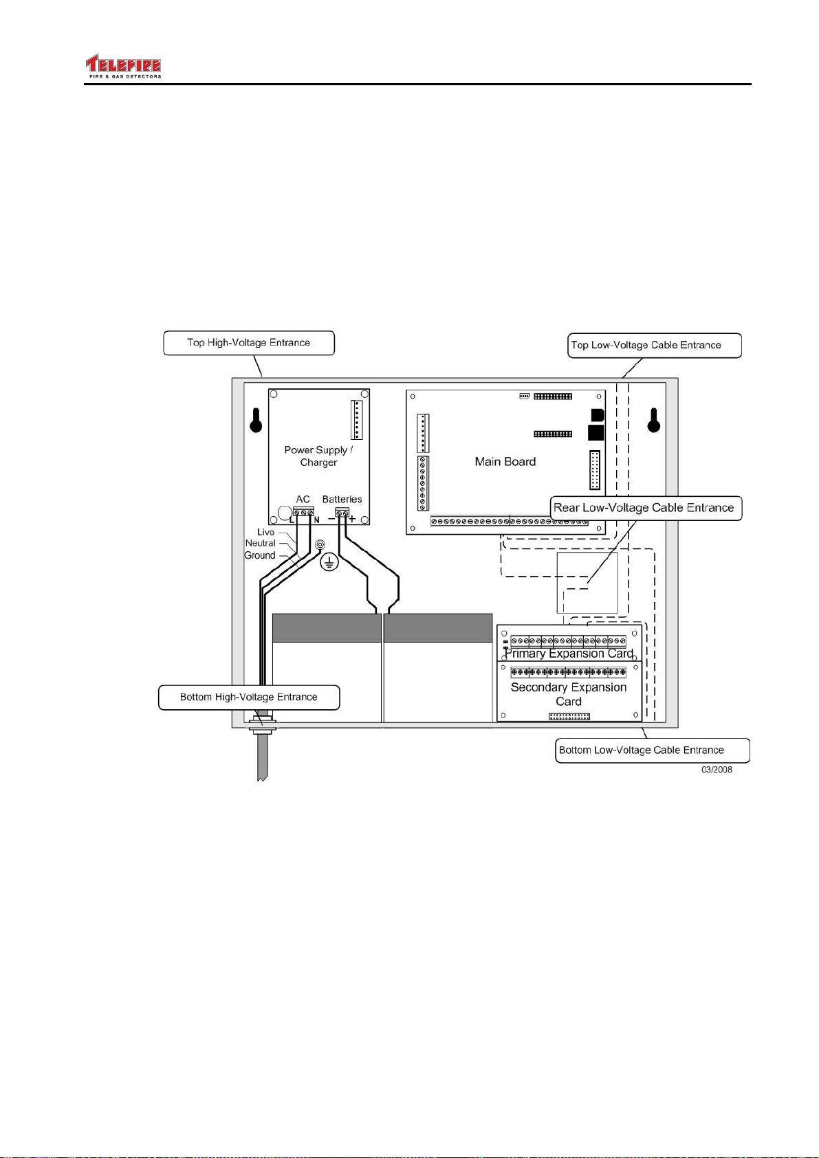
TSA-1000
© 2008 – 2012 Telefire Fire & Gas Detectors Ltd Revision 1.12 האיגש !אצמנ אל הינפהה רוקמ. 2
11.3.4 Input Wiring
Input wiring for detectors and push buttons shall be with a two-wire cable according to
the local regulations.
Special detectors such as beam detectors or gas detectors shall be connected by a 4wire cable.
In industrial installations which have machines which produce high power
electromagnetic fields, use shielded cables.
Detector wiring shall be in a separate conduit from mains conduit.
The wiring cables and input and system output shall be separate from mains AC input –
see Figure 9.
Figure 9 Routing High- and Low Voltage cables in the TSA-1000 Chassis
11.3.5 24Vdc Powered Devices
To ensure operation of alarm or initiating device that requires relatively high current from
a 24 Vdc source, use appropriate cables.
Wire specifications should be between 12 and 18 AWG and the cable resistance running
between the 24 Vdc source to the I/O module and from the I/O module to the device
should be calculated. Ensure that no device receives a voltage below its specified
minimum operating value and that the total voltage drop will not exceed 3 volts.
Calculate the total current drawn by the system and system devices at normal operation
and alarm modes. Ensure that the total load on the power supply does not exceed its
limit of 1.5 Ampere.
– Page 40 of 40 –
Page 49
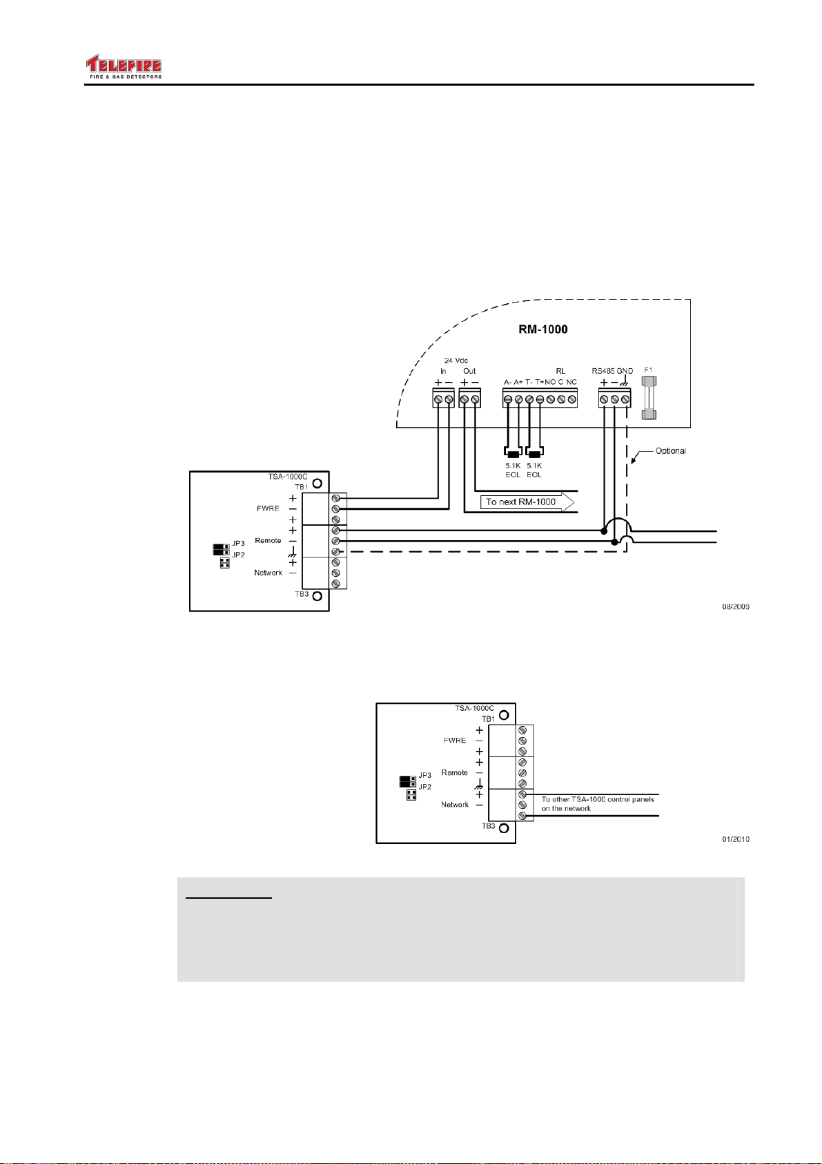
TSA-1000
© 2008 – 2012 Telefire Fire & Gas Detectors Ltd Revision 1.12 האיגש !אצמנ אל הינפהה רוקמ. 2
11.3.6 Output Wiring
Activation circuit cabling between the 24Vdc source to the output device such as
sounders, extinguishing devices, strobes, etc., shall be calculated to a maximum voltage
drop of 3V or a voltage drop that will leave the device with the lowest operating voltage
specified by the manufacturer – the lowest voltage drop of the two.
11.3.7 Remote Panel Wiring
RM-1000 remote panels are connected to the control panel via 4-wire connection. One
pair of RS-485 wires and one pair for 24Vdc supply.
Figure 10 RM-1000 connection
11.3.8 Control Panel Network Wiring
Control panel networking shall be done via a pair of RS-485 wires.
Figure 11 Connecting a network
Warning
!
Disconnect all power supplies, (main and batteries) before connecting
or disconnecting cables to the control panel.
Ensure that the system operates normally and that there are no zones in
alarm prior to connecting or replacing extinguishing devices.
11.3.9 End Of Line device (E.O.L.)
Install the End Of Line Device (E.O.L.) to the last device in the zone or output.
– Page 41 of 41 –
Page 50
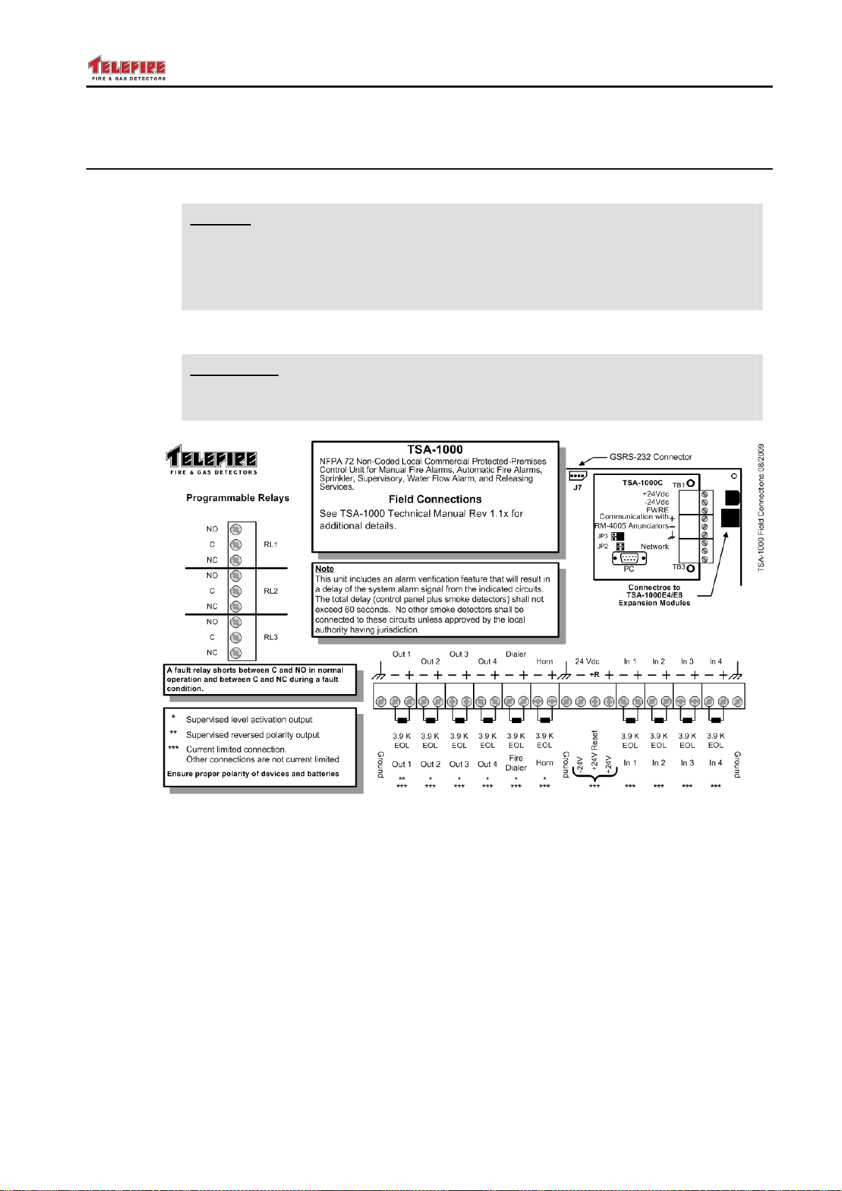
TSA-1000
© 2008 – 2012 Telefire Fire & Gas Detectors Ltd Revision 1.12 האיגש !אצמנ אל הינפהה רוקמ. 2
11.4 Installing Detectors, Input and Output Devices, and Other
Devices
11.4.1 Connecting Zones and Outputs
Note
i
Connect the zones, 24 volt output and control panel outputs (dialer, horn, programmable
outputs and relays) to the control panel.
!
Measure the wiring to ensure there are no shorts before connecting the wiring
to the control panel.
Connecting or adding zone, devices, outputs etc shall be done when all
power to the control power is disconnected (AC and batteries disconnected).
Warning
Do not connect the extinguishing activation circuits at this time. Use a
dummy load.
Figure 12 Main Board Connectors
– Page 42 of 42 –
Page 51
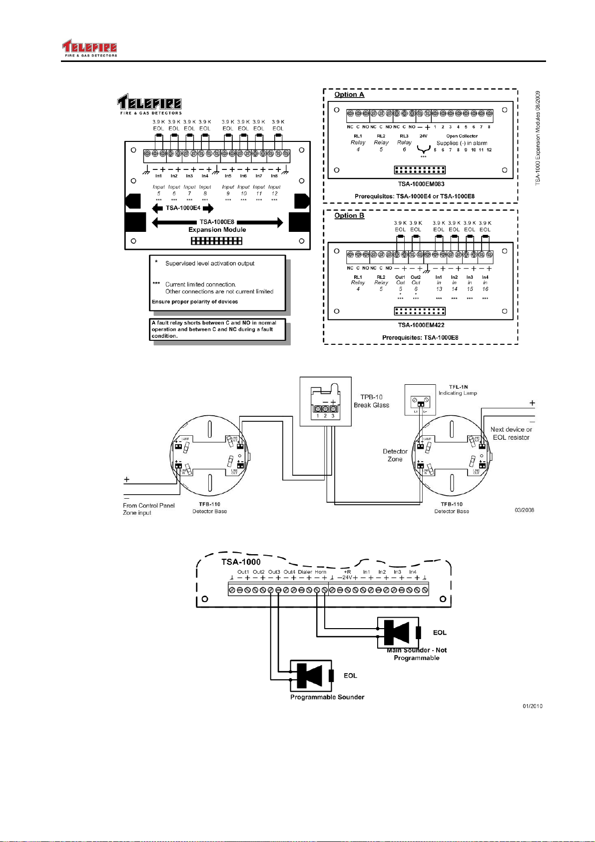
TSA-1000
© 2008 – 2012 Telefire Fire & Gas Detectors Ltd Revision 1.12 האיגש !אצמנ אל הינפהה רוקמ. 2
Figure 13 Expansion Module Connectors
Figure 14 Connecting Two Detectors and a TPB-10R Break-Glass
Figure 15 Connecting Programmable and General Sounders
– Page 43 of 43 –
Page 52
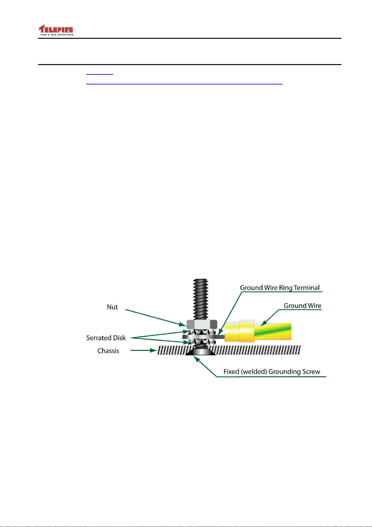
TSA-1000
© 2008 – 2012 Telefire Fire & Gas Detectors Ltd Revision 1.12 האיגש !אצמנ אל הינפהה רוקמ. 2
11.5 Connecting the mains, batteries and the ground wire.
SEE SAFETY, page 9
SEE Routing cables into the ECD and maintaining the protection level, page 38
Connect the control panel’s AC input line directly to a dedicated circuit breaker that is not
shared by other appliances or equipment. It is recommended that the circuit breaker
shall be labeled “FIRE ALARM”.
Use a three wire cable (Line, Neutral and Ground wires) of the appropriate gauge
Verify that all power sources to the ECD are disconnected.
Disconnect the ECD AC cable from the mains, so that the ECD ends of the wires can be
handled safely.
Insert the AC input power cable to the control panel enclosure through either the top left
or bottom left knockout opening and keep it separated and distant from the field wiring
and the control panel circuits.
Use appropriate bushing/grommet that fits the knockout openings, to ascertain that there
are no sharp edges, to prevent damage or abrasion to the cable during assembly and
use.
Connect the GND (yellow/green) wire to the dedicated grounding screw located below
the PS, using the appropriate hardware as shown in Fig. 7 below, thus connecting the
chassis to the grounding wire
CONNECT THE GROUND WIRE OF THE AC INPUT CABLE DIRECTLY THE PANEL'S
CHASSIS GROUND SCREW, USING SERRATED WASHERS AS SHOWN.
Figure 16 Connecting the grounding wire to the Chassis
Then connect the Line and Neutral wires to the proper terminal. Tighten the terminal
block screws.
VERIFY THAT THE ECD IS PROPERLY GROUNDED BEFORE CONNECTING AC
POWER TO THE ECD.
Connecting the batteries: Connect the supplied link wire between the batteries, and then
connect the long Red wire o the + terminal of one battery and to the +bat terminal block,,
and the long black wire to the –terminal of the battery and the –bat terminal block
– Page 44 of 44 –
Page 53

TSA-1000
© 2008 – 2012 Telefire Fire & Gas Detectors Ltd Revision 1.12 האיגש !אצמנ אל הינפהה רוקמ. 2
Observe Batteries polarity. Wrong connection can cause damage to the ECD.
Connect AC input power.
Verify that the ECD is working properly; the alphanumeric display scrolls the character 8
from left to right and only the Power led is ON.
11.6 Post-Installation
11.6.1 Switching the Control Panel On
Activate the control panel and ensure that it is working properly (the digital display
moves the figure 8 from left to right and only the power led is on).
11.6.2 Configuring the Control Panel
The ECD is delivered in a default configuration.
Modify only if necessary, by programming the ECD, as explained in Control Panel
Programming, page 55
The time and date must be updated' the password has to be modified, etc
11.6.3 Setting the Date and Time
The TSA-1000 includes a real-time clock and calendar that are used for logging system
events. Ensure that you set the date and time after powering on (see section 15.7 on
page 66). The clock/calendar circuit includes a power backup for about five hours
without power sources – verify and set the time and date if the TSA-1000 was powered
off more than 5 hours.
11.6.4 Control Panel Programming
Program the control panel configuration and activation matrix. Chapter 0 on page 52
has detailed programming information.
11.6.5 Field Test
Perform a field test – this test allows a single operator to perform a test for all field
devices, including detectors, call points, and other inputs (see page 65 for instructions
for performing Field Test).
The testing process is automatic except for activation of the device which is done
manually by means specified by the device's manufacturer.
Telefire's devices can be tested by putting a magnet to the test point of the detectors or
activation of the call points through the testing tool (supplied with the call point).
11.6.6 Activation Test
Test the outputs of the system to ensure that they are activated according to the
conditions specified by the consultants.
11.6.7 Arming Extinguishing Devices
Ensure all input devices are in normal state and no devices are in alarm.
11.6.8 Change Password
It is recommended to change the operator password after completing the installation and
system testing. See section 15.6 on page 66 for explanation on changing passwords.
– Page 45 of 45 –
Page 54
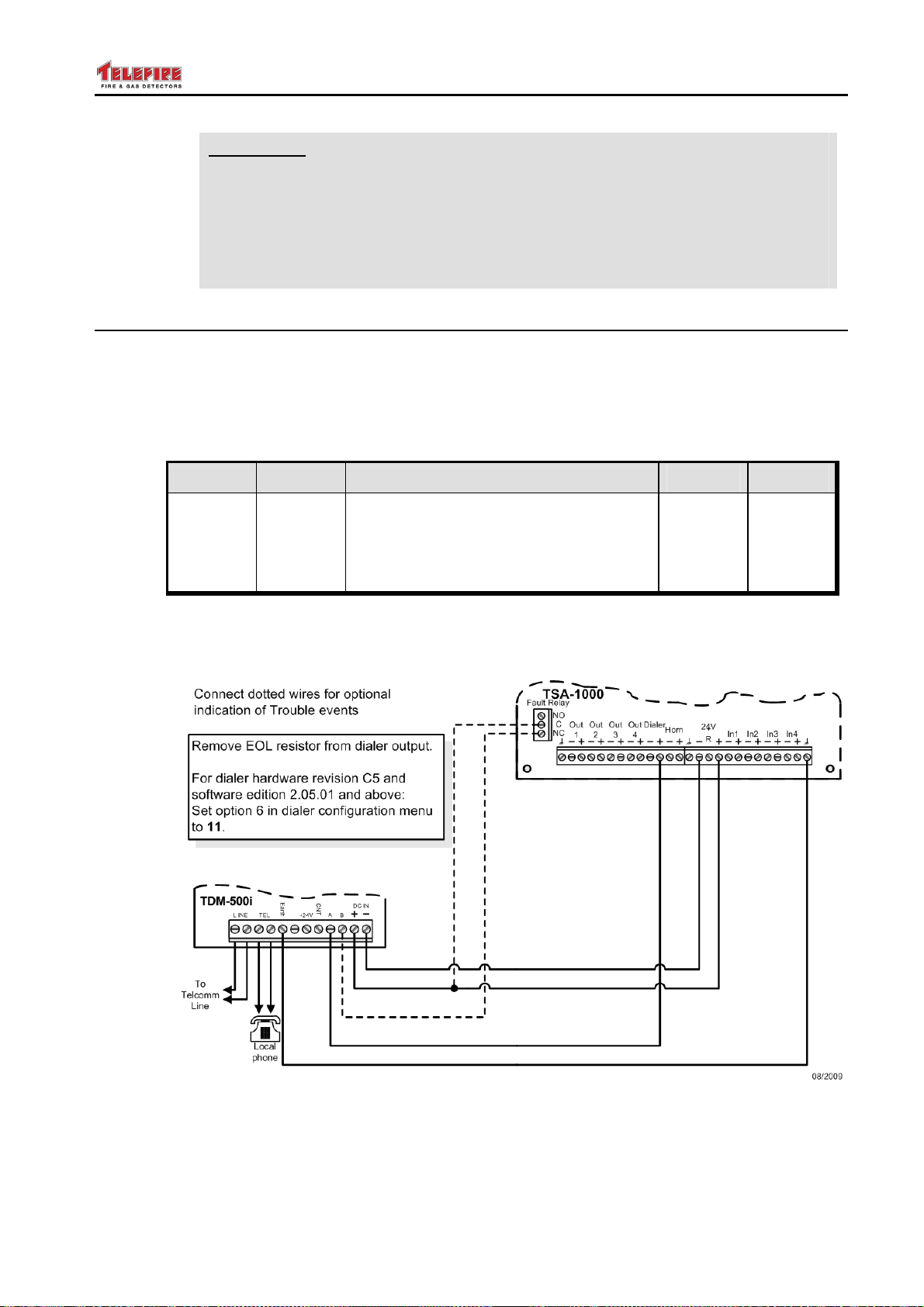
TSA-1000
© 2008 – 2012 Telefire Fire & Gas Detectors Ltd Revision 1.12 האיגש !אצמנ אל הינפהה רוקמ. 2
Warning
!
Forgotten passwords require factory reset: if you lose or forget the
password, the panel must be sent back to the factory to be initialized.
There is no field option for gaining access to the panel without a valid
password.
Once you have changed the password, it is important that you write it
down somewhere and store it in a safe place.
11.7 Connecting a TDM-500i Dialer
11.7.1 Dialer Configuration
Verify that dialer software version is revision 2.01.08 or higher (see label on TDM-500i).
Press Prog – the display shall show "_." enter the password (default 2222). The display
shall show P.
Press 1. The display shall show d.
Press Display Configuration Range Default
6 – Selection of A and B input polarity"
11 – A positive, B positive
(option exists only from software
revision 2.05.01)
Configure the dialer for positive activation of both input A and input B (11).
00 – 11 01
11.7.2 Dialer Connection
Figure 17 Connecting a TDM-500i Dialer (W/W rev C5, S/W rev 2.05.01)
– Page 46 of 46 –
Page 55

TSA-1000
© 2008 – 2012 Telefire Fire & Gas Detectors Ltd Revision 1.12 האיגש !אצמנ אל הינפהה רוקמ. 2
Note
i
The dotted lines in Figure 17 are required only for error message
notifications.
Configure the dialer (option 6) to 11.
– Page 47 of 47 –
Page 56

TSA-1000
© 2008 – 2012 Telefire Fire & Gas Detectors Ltd Revision 1.12 האיגש !אצמנ אל הינפהה רוקמ. 2
12 Extinguishing
Extinguishing can start manually or by automatic operation,.
12.1 Automatic Extinguishing
After receiving an alarm from a zone or across zones that belong to the automatic
extinguishing outputs, the extinguishing process starts. In case an extinguishing delay
was defined, the delay system starts to operate. At the end of the delay the
extinguishing output is activated for (default) 20 seconds.
12.2 Manual Extinguishing
The extinguisher output can be triggered by manual operation, by pressing the Manual
Release Push Button.
12.3 Extinguishing Output
A programmable output that is configured as an extinguishing output (E) differs from an
output that is configured as an "And" matrix in several ways:
• An extinguishing output supplies an 20 second pulse, as opposed to a regular
output that stays on until the panel is reset or silenced
• An extinguishing output supplies a higher current
• An extinguishing output has a higher priority when allocating currents
• An extinguishing output can be configured to be triggered by a single input
• And extinguishing matrix may optionally include inputs (Pressostat, Emergency
Abort, Emergency Hold, Gas flow switch, or Manual Only switch)
• Activation of an extinguishing output will result in a notification that extinguishing
was activated in the control panel. Pressing the Reset key will not cancel this
indication in order to ensure extinguishing agent replacement or refill
12.4 Emergency Hold and Emergency Abort
The TSA-1000 supports emergency hold and emergency abort as per EN-12094-1.
Pressing an emergency hold switch will start one of the following sequences:
• The extinguishing signal shall not be activated as long as the emergency hold
device is continuously operated. De-activation of the operation of the emergency
hold device after the end of the count-down shall activate extinguishing immediately.
• The extinguishing signal shall not be activated as long as the emergency hold
device is continuously operated. The pre-discharge warning time shall be re-started
from the beginning by each release of the emergency hold device.
Pressing the emergency abort switch during quiescent state or during activation countdown shall inhibit extinguishing release until the emergency abort device is released and
the control panel is reset by the operator.
12.5 Post-Activation Indication
After activation of an extinguishing output, the digital display will show E#.A with the
middle digit indicating the activated extinguishing output. For example, activating
extinguishing output 3 will display E3.A. Pressing the Reset key will not cancel this
indication, in order to verify extinguishing agent replacement or refill.
The Fault LED is also switched on.
– Page 48 of 48 –
Page 57

TSA-1000
© 2008 – 2012 Telefire Fire & Gas Detectors Ltd Revision 1.12 האיגש !אצמנ אל הינפהה רוקמ. 2
Programmable output 1 defined as an extinguishing output will provide upon activation
24VDC and a current of 1.4A for 20 seconds. Programmable output 1 operates in
“Reversed Polarity” mode.
Other outputs that are defined as extinguishing outputs will provide upon activation
24Vdc and a current of 1.0A for 20 seconds. These outputs operate in "Level Activation"
mode.
12.6 Actions to Perform After Extinguishing Activation
After extinguishing activation, the control panel will show E#.A (Extinguishing #
Activated) with the middle digit indicating the output that was activated.
Pressing the Reset key will not cancel this indication, in order to remind the user that
cylinder replacement or refill is required.
Fill /Replace extinguisher and fix all pending faults.
12.7 Reestablishing the Quiescent Condition after Extinguishing
After ALL the issues are resolved, all faults (if an) are fixed, and the Extinguisher is
replenished and brought to working order,
The ECD can be set to the Quiescent (idle) state.
This requires entering and exiting the programming mode.
To do this, using the ECD keyboard, perform the following;
Press Menu to enter the main menu. Press the ▲ or ▼ keys until the display shows PG
(programming mode). Press Enter to enter programming mode. The display will flash
PAS (password) and the TSA-1000 will wait for the password (default 2222).
Key-in the password
and then perform RESET.
If there no other problems or faults, the ECD shall return to the quiescent state.
Note
i
Verify that the control panel is back to normal operation, the digital display scrolls the
figure 8 from left to right.
To return the control panel to normal operation, enter programming mode and
then return the control panel to normal operation by pressing the Reset key.
This action shall be performed by authorized personnel.
– Page 49 of 49 –
Page 58
TSA-1000
© 2008 – 2012 Telefire Fire & Gas Detectors Ltd Revision 1.12 האיגש !אצמנ אל הינפהה רוקמ. 2
13 Connecting Extinguishing Equipment
13.1 Extinguishing Adapters
In order to connect the ECD extinguishing output to different actuators, it is necessary to
connect adapters between the ECD output and the extinguishing equipment input,
Telefire offers several adapters.
Shown below are the type of equipment and the relevant adapter:
Fike FIRERASER cylinders-use TLA-130 adapter
Fike GCA cylinder-use TLA-22 adapter
Greenex Aerosol Containers-use TLA-33 adapter
FirePro Aerosol Containers-use TLA-44 adapter
SAFE Solenoid Activated gas containers-use TLA- 110 adapter
Note
i
When extinguishing adapters are installed, addition of EOL resistors is not
required!
Note
i
Please consult the manufacturer for solutions regarding activation of
additional extinguishing devices.
13.2 Number of Extinguishing Adapters
Extinguishing Device Maximal number of extinguishing adapters
SAFE solenoid gas
cylinders
FIKE solenoid gas
cylinders (FIRERASER)
FIKE GCA gas cylinders A single TLA-22 adaptor connected to the extinguishing
FirePro aerosol generators A single TLA-44/1 or TLA-44/4 adaptor connected to the
GreenEX aerosol
generators
A single TLA-110 adaptor connected to the extinguishing
output
A single TLA-130 adaptor connected to the extinguishing
output
output
extinguishing output
A single TLA-33 adaptor connected to the extinguishing
output
Note
i
– Page 50 of 50 –
Connect a single extinguishing adaptor to the extinguishing activation output.
This adaptor will activate a single extinguishing device, except for the TLA44/4 that can activate up to 4 FirePro aerosol extinguishers.
Please consult the manufacturer for solutions regarding activations of
additional extinguishing devices
Page 59
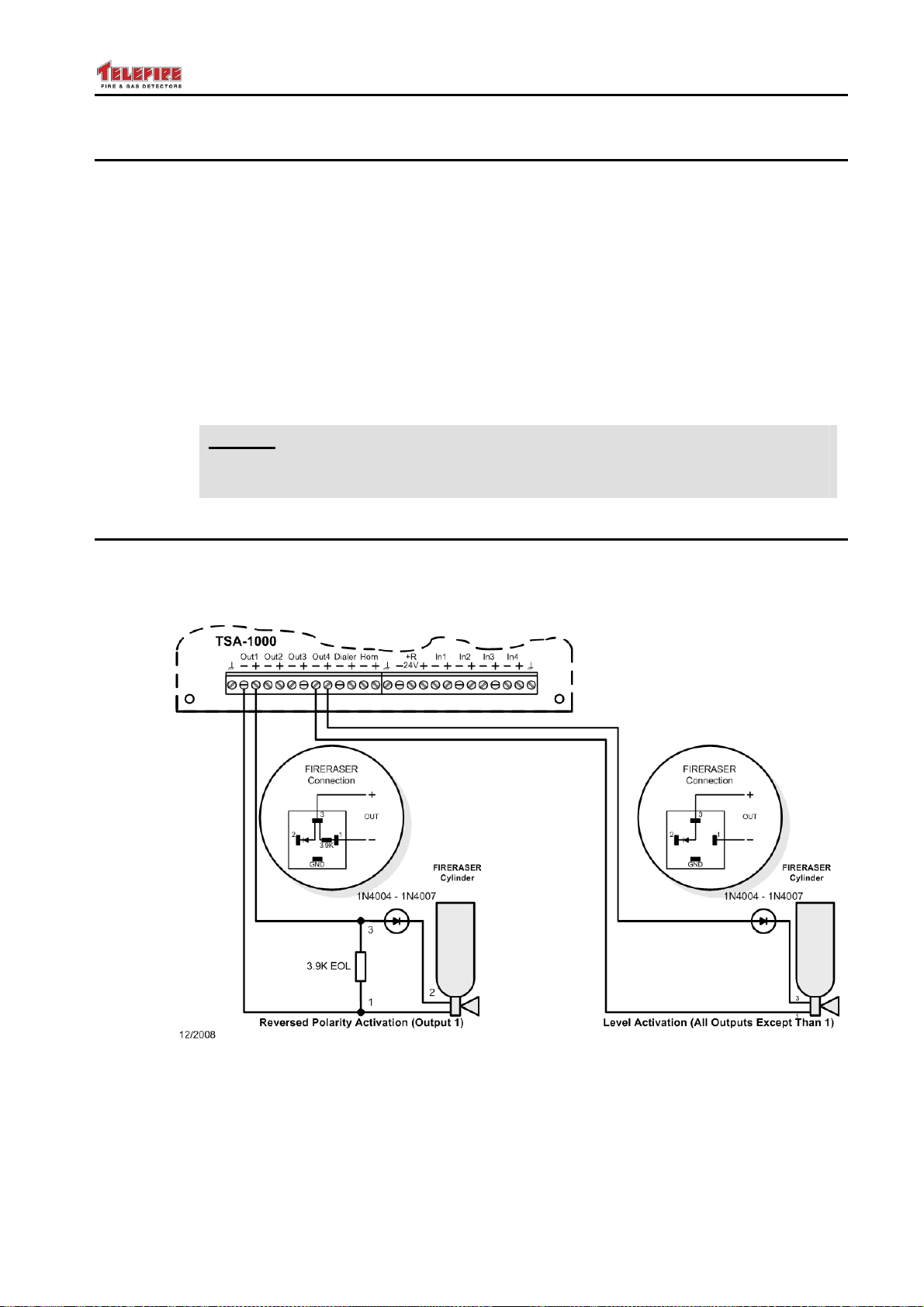
TSA-1000
© 2008 – 2012 Telefire Fire & Gas Detectors Ltd Revision 1.12 האיגש !אצמנ אל הינפהה רוקמ. 2
13.3 Extinguishant Quantities
• It is possible to connect up to three, simultaneously activated solenoid-operated
containers to the TSA-1000. Additional containers may be activated with a delay of
at least 20 seconds between activations
• It is possible to connect a single GCA-activated container to the TSA-1000 – this will
be connected only to output 1 (see Figure 19)
• It is possible to connect one GreenEX aerosol releasing device to each
programmable output on the TSA-1000
• It is possible to connect one TLA-44 to each programmable output, as long as there
are no simultaneous activations. Multiple outputs may be activated with a delay of
at least 20 seconds between activations. Each TLA-44/1 module can activate a
single FirePro aerosol generator, while each TLA-44/4 module can activate up to 4
FirePro aerosol generators.
Note
i
Please consult the manufacturer for solutions regarding activations of
additional extinguishing devices
13.4 Fike FIRERASER
Fike's FIRERASER cylinders are suitable with work for all of Telefire control panels.
For additional detail, refer to Fike’s technical manual.
Figure 18 Connecting a FIRERASER Cylinder for Automatic Extinguishing
– Page 51 of 51 –
Page 60
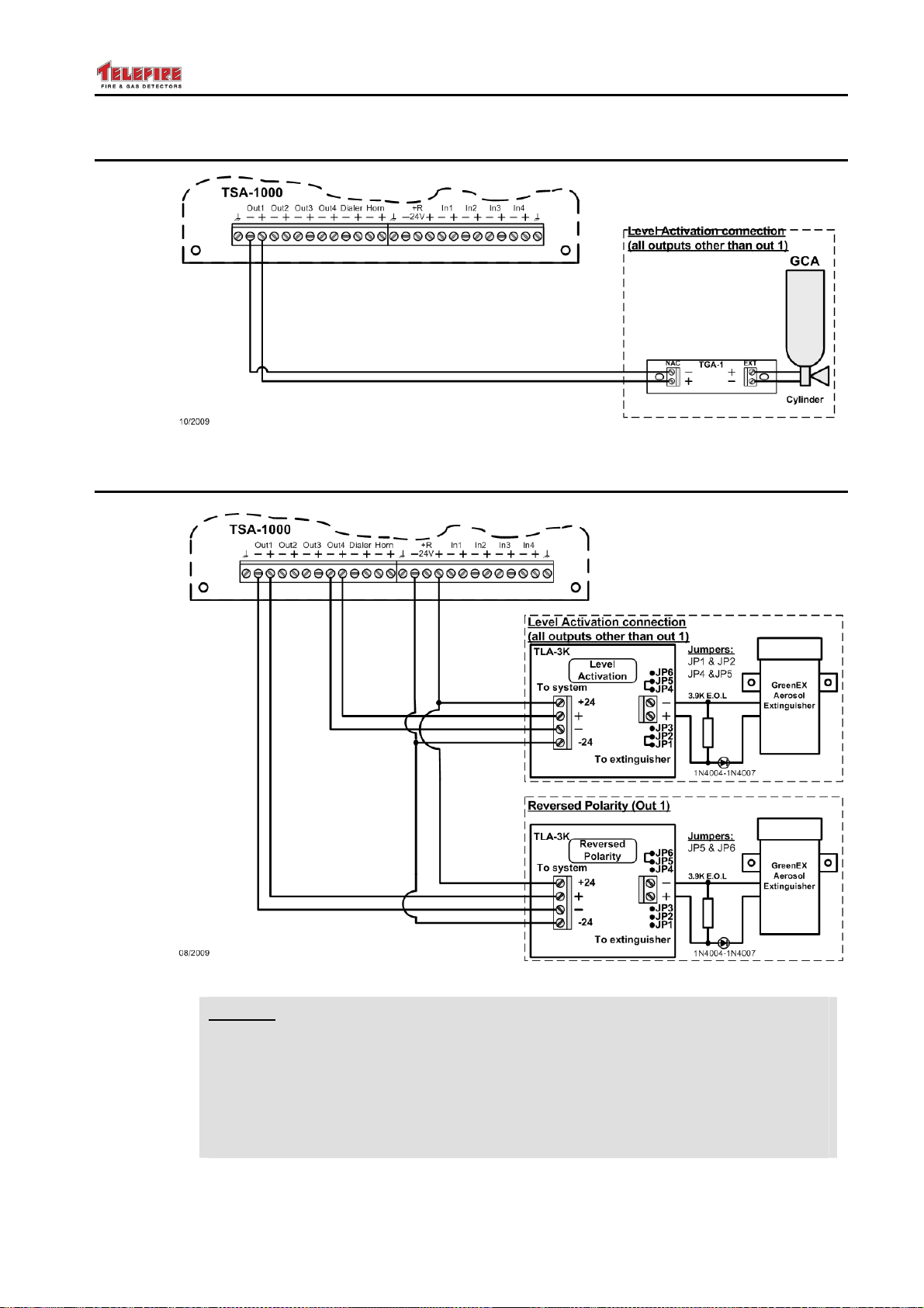
TSA-1000
© 2008 – 2012 Telefire Fire & Gas Detectors Ltd Revision 1.12 האיגש !אצמנ אל הינפהה רוקמ. 2
13.5 Fike GCA
Figure 19 Connecting a GCA-Activated Extinguishing Cylinder
13.6 GreenEX Aerosol Containers
Figure 20 Connecting a GreenEX Aerosol Extinguishing Container
Note
i
– Page 52 of 52 –
When connecting a TLA-3K module to programmable output 1 in a
TSA-1000 verify that jumpers JP5 and JP6 are shorted.
When connecting a TLA-3K module to programmable all other outputs in a
TSA-1000 ensure that jumpers JP1 and JP2 are shorted and jumpers JP4
and JP5 are shorted.
See Figure 20 above.
Page 61
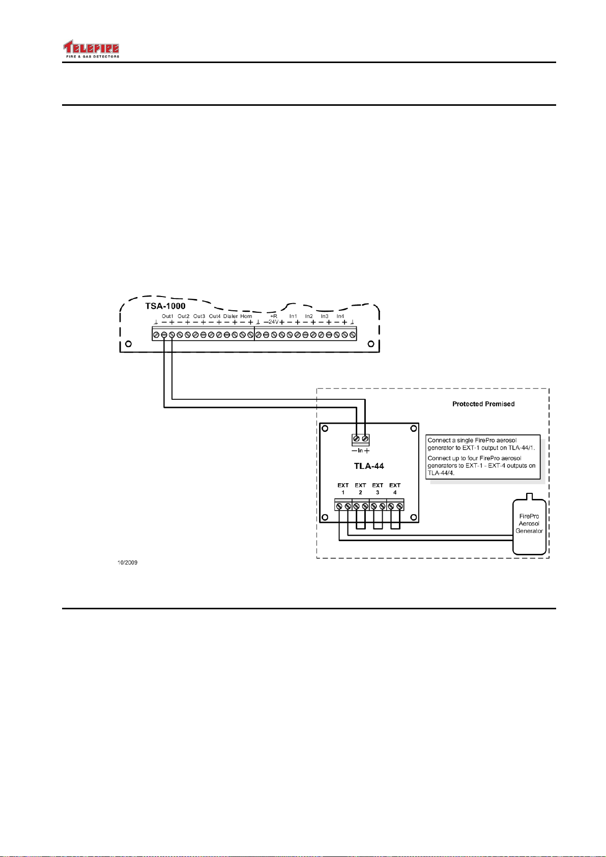
TSA-1000
© 2008 – 2012 Telefire Fire & Gas Detectors Ltd Revision 1.12 האיגש !אצמנ אל הינפהה רוקמ. 2
13.7 FirePro Aerosol Containers
Aerosol releasing devices made by different manufacturers differ from each other in their
power requirements and therefore require different interface modules.
The TLA-44 module is intended to work with FirePro aerosol units. It is available in two
configurations that allow for connecting either a single module or up to four modules.
• TLA-44/1 – allows activation of a single module
• TLA-44/4 – allows activation of up to four modules
Activation is simultaneous to all aerosol devices connected to the TLA-44. The module's
output lines to the aerosol devices are supervised for open circuit.
The TLA-44 is intended to be installed in the same protected space as the aerosol
devices.
The TLA-44 may be connected to outputs with level activation or reversed polarity
activation.
Figure 21 Connecting FirePro Aerosol Generators
13.8 A Typical Application – Extinguishing and Electricity Disconnect
The following example shows a TSA-1000 that is configured to activate extinguishing by
cross-zone of zones 2 and 3, or activation of a manual extinguishing call point on
zone 4; activating an extinguishing release sign on output 2; activating an evacuation
horn on output 3; triggering electricity disconnect by relay RL3; and connection of a
pressure switch to supervise the extinguishant pressure on zone 1.
Figure 22 shows a system that was configured as follows:
• Relay 3 – activated by cross-zone (A) of inputs 2 and 3, or input 4; not delayed;
unsilenced
• Input 1 – pressure switch input (Ξ)
• Inputs 2 and 3 – standard detection zones (d); no delay
• Input 4 – pushbutton input (P)
– Page 53 of 53 –
Page 62
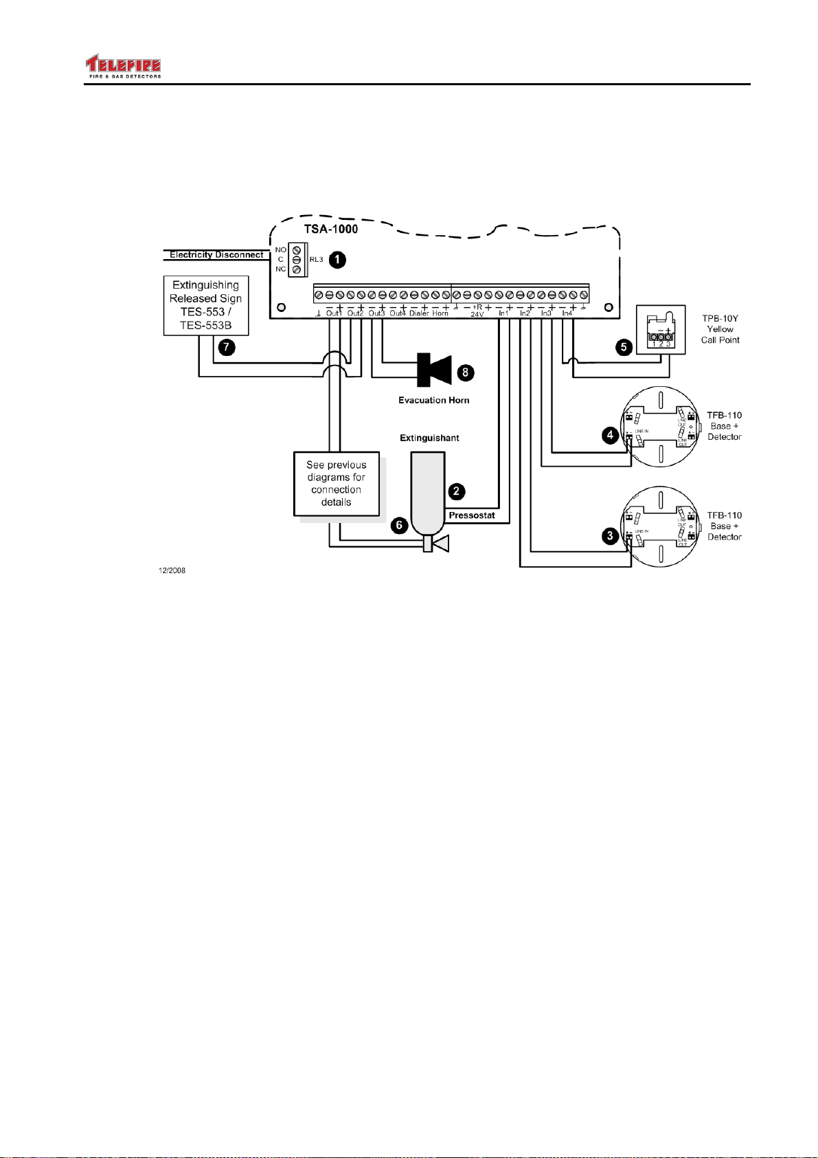
TSA-1000
© 2008 – 2012 Telefire Fire & Gas Detectors Ltd Revision 1.12 האיגש !אצמנ אל הינפהה רוקמ. 2
• Output 1 – extinguishing output (E); 30 second delay; activated by cross-zone of
inputs 2 and 3, or input 4; not delayed
• Outputs 2 and 3 – activated by cross-zone (A) of inputs 2 and 3, or input 4; not
delayed; unsilenced
Figure 22 A typical application – cross-zone activation of electricity disconnect,
evacuation volume extinguishing
– Page 54 of 54 –
Page 63
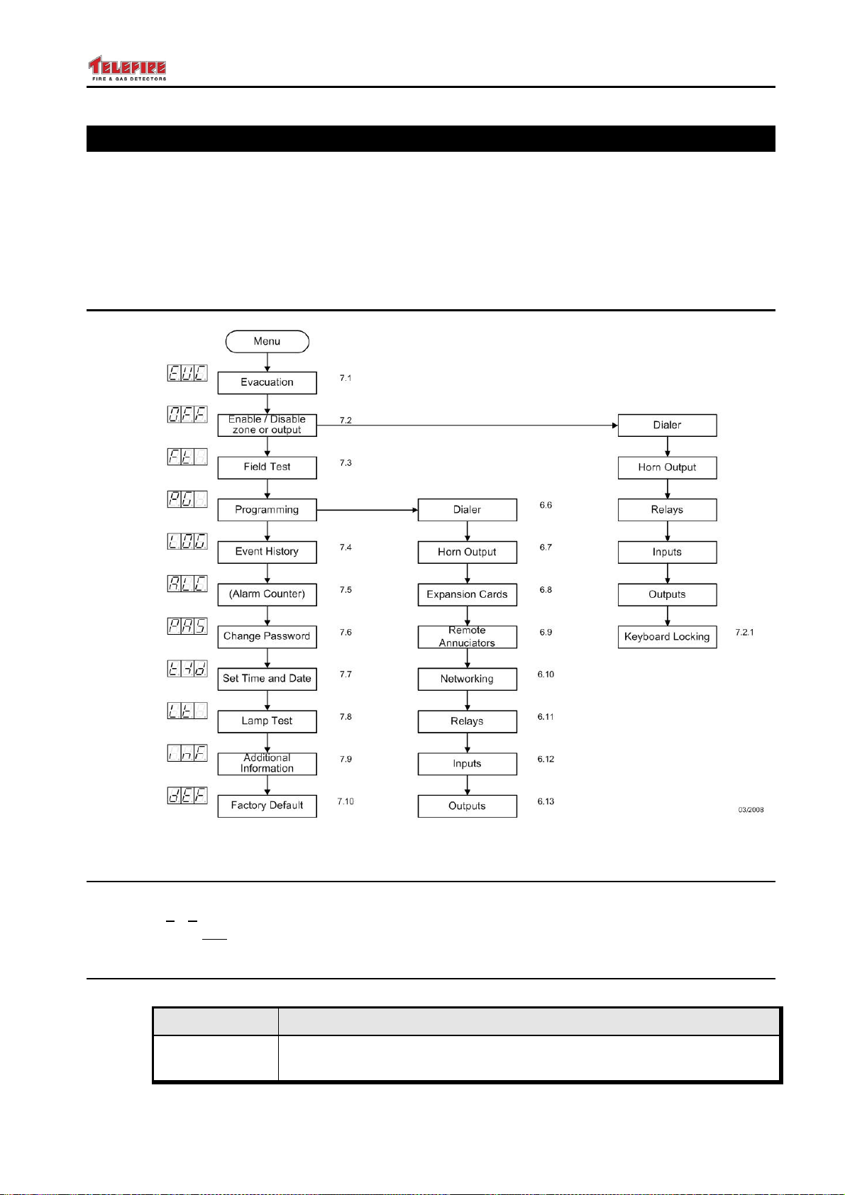
TSA-1000
© 2008 – 2012 Telefire Fire & Gas Detectors Ltd Revision 1.12 האיגש !אצמנ אל הינפהה רוקמ. 2
14 Control Panel Programming
The TSA-1000's operating parameters can be easily modified in the field to allow for the
specific requirements of each site.
System parameters modification is limited to access level 3 (programmer).
After entering programming mode you can modify the general settings (expansion
modules, remote panels, and relay activation conditions); zone configuration, and output
activation conditions.
14.1 Menu Structure
Figure 23 Programming Menu Structure
14.2 Entering Programming Mode
Press Menu to enter the main menu. Press the ▲ or ▼ keys until the display shows PG
(programming mode). Press Enter to enter programming mode. The display will flash
PAS (password) and the TSA-1000 will wait for the password (default 2222).
14.3 Key Functions during Programming
The keyboard has different functions in programming mode.
Key Function in Programming Mode
Menu (1)
– Page 55 of 55 –
Moves the "cursor" between programmable fields that vary according
to the device and type selected
Page 64
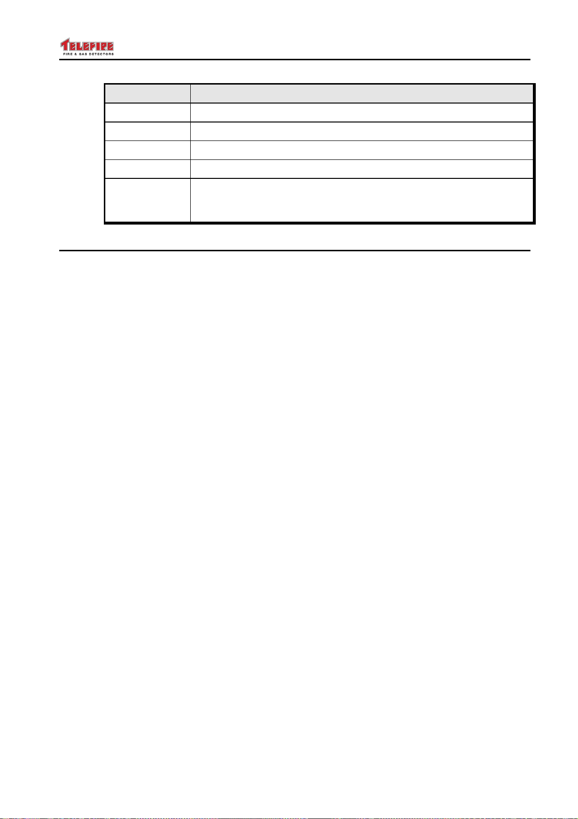
TSA-1000
© 2008 – 2012 Telefire Fire & Gas Detectors Ltd Revision 1.12 האיגש !אצמנ אל הינפהה רוקמ. 2
Key Function in Programming Mode
▲ (2) Navigates between options available in the selected field
▼ (3) Navigates between options available in the selected field
Enter (4)
Ack/Prog (5)
Selects, marks or removes a zone from the matrix
Copies the temporary programming to the non-volatile memory
Reset Exits programming mode without saving. The display shows nSv (not
Saved) and will return to programming mode after a few seconds.
Pressing the Reset key a second time will exit without saving.
14.4 Display During Programming
During programming the 3-digit 7 segment display represents:
• Leftmost digit – device type
• Middle digit – device (input, output, or relay) number
• Right digit – mode of operation
Event type field (the top three LEDs to the right of the digital display) will indicate the
event type (alarm, fault or supervisory)
Delay field – represented by the six left LEDs and the bottom five LEDs on the right of
the general display area indicate delay time in steps of 5 seconds.
The Alarm LED indicates alarm verification for inputs and Silenced for outputs.
The zone indicators represent input zones for output matrix programming. During matrix
programming when the alarm zone LED is lit, it means that activating this zone will
cause an alarm condition. During matrix programming when the supervisory zone LED
is lit, it means that activating this zone will cause a supervisory fault condition.
Selected fields blink when selected.
– Page 56 of 56 –
Page 65
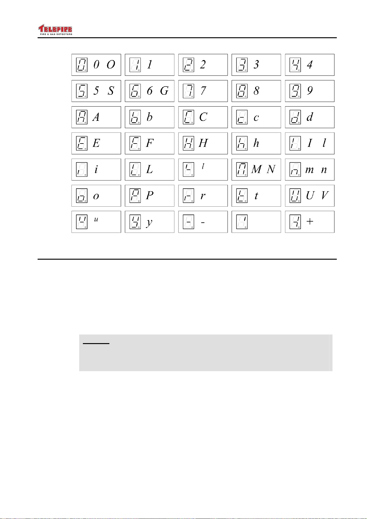
TSA-1000
© 2008 – 2012 Telefire Fire & Gas Detectors Ltd Revision 1.12 האיגש !אצמנ אל הינפהה רוקמ. 2
Figure 24 The seven-segment display and representation of digits and letters
14.5 Programming Sequence
14.5.1 Programming Steps
There are five steps to programming the control panel:
• Enter programming mode
• Program the control panel's general parameters
• Program inputs
• Program output modes and matrices
• Save to non-volatile memory
Note
i
14.5.2 Programming Sequence for Each Parameter
For each control parameter the programming sequence is as follows:
• Select the device type (left digit)
• Press the Menu key to move the cursor to the middle digit and select the device
• Press the Menu key to move the cursor to the right digit and select the device mode
• Press the Menu key to move the cursor to select the event type with the LEDs to the
• Press the Menu key to move the cursor to select the delay. Each LED in this field
When in programming mode, the buzzer sound after 30 minutes without use
of the keyboard to remind you not to leave the control panel in programming
mode.
number
right of the digital display
represents a delay of 5 seconds
– Page 57 of 57 –
Page 66
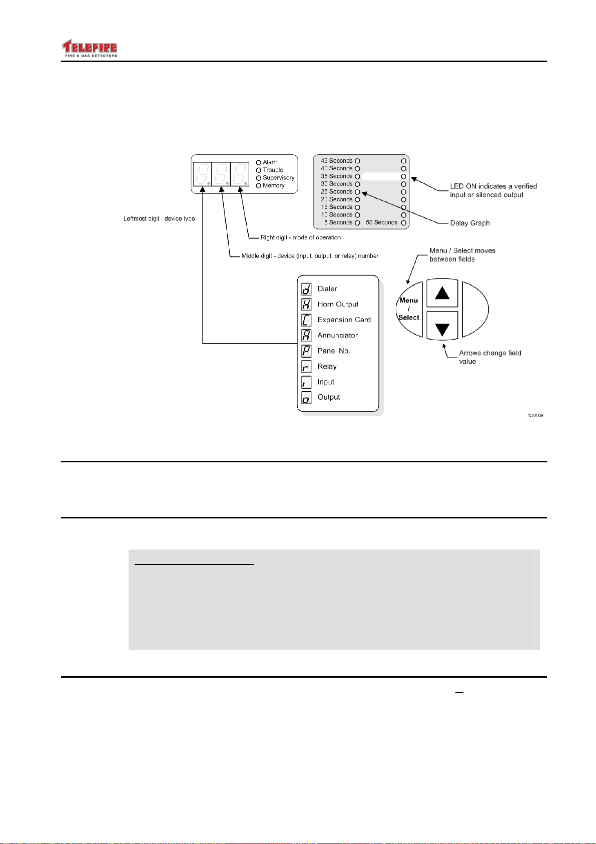
TSA-1000
© 2008 – 2012 Telefire Fire & Gas Detectors Ltd Revision 1.12 האיגש !אצמנ אל הינפהה רוקמ. 2
• Press the Menu key to move the cursor to select verification for input devices or
silenced for output devices (Alarm LED) or delay
• Press the Menu key to move the cursor to select the input zones for the matrix
(alarm LED of the in the zone display area)
Figure 25 Device selection
14.6 Dialer Programming
The dialer's operating function is fixed – the display shows d1G (dialer output is general
output).
14.7 Horn Output Programming
The horn's operating function is fixed except for the requirement of CP-10 (see below) –
the display shows H1G (dialer output is general output).
CP 10
CP 10 Requirement
CP-10 specifies that in some cases the horn output may not be silenced for 3
minutes after alarm. To set this requirement press Menu until the third digit
(G) will blink and use the ▲ or ▼ keys until the dot will show (feature enabled
– H1G., feature disabled – H1G).
When enabling this feature, paste a label stating "Bell silence is disabled
for a period of 3 minutes upon first alarm" on the front door of the panel.
14.8 Expansion Card Programming
During expansion card programming the left digit will be C (expansion Card). The
middle digit represents the card number (1 – first expansion module, 2 – second module,
etc). Do not skip card numbers (i.e., do not program card 2 if you do not have card 1
installed). The right digit will show the card type:
• 0 – not installed
• 1 – TSA-1000E8 (8 zones)
– Page 58 of 58 –
Page 67

TSA-1000
© 2008 – 2012 Telefire Fire & Gas Detectors Ltd Revision 1.12 האיגש !אצמנ אל הינפהה רוקמ. 2
• 2 – TSA-1000E8 (8 zones) and TSA-1000EM083 (8 open collector outputs + 3
relays)
• 3 – TSA-1000E8 (8 zones) and TSA-1000EM422 (4 zones, 2 programmable
outputs, 2 relays)
• 4 – TSA-1000E4 (4 zones)
• 5 – TSA-1000E4 (4 zones) and TSA-1000EM083 (8 open collector outputs + 3
relays)
Note
i
The card type represents the number of Inputs, Outputs, and Relays:
TSA-1000EM-IOR (I = number of inputs, O = number of outputs,
R = number of relays)
14.9 Remote Annunciator Programming
During Annunciator programming the left digit will be A (Annunciator). The middle digit
represents the annunciator's number (1 – 4). The right digit represents the annunciator's
type (0 – not configured, E – English, S – Secondary language).
14.10 Network Programming
TSA-1000 control panel networking is in main/sub configuration. All panels require the
optional TSA-1000C communication network. Physical connection is via a two-wire
RS-485 cable.
A single Master Panel (panel No. 1) supervises up to 12 Sub Panels (panel addresses 5
to 16). The Master Panel uses its own zones 1 – 4, and indicates alarm and fault events
on panels 5 – 16 as zones 5 – 16.
An alarm at any Sub Panel will activate all sounders (Horn output on the main board and
any output defined as "General, Silenceable" on the main or expansion boards) of all
control panels on the network. Am alarm can be silenced or reset only from the control
panel that initiated the alarm or from the Master Panel.
14.10.1 Configuring the Main Panel
From the main programming menu press the ▲ or ▼ keys until the display changes to
the panel number. Using the Menu, ▲, and ▼ keys set panel as panel No. 1. Press
Menu again to select the sub panels. Zone 5 LED will flash – press Enter to include
panel 5 as a sub-panel. Use the ▲ or ▼ keys to move to panels 6 – 16 to enable
additional panels.
14.10.2 Configuring Sub Panels
Set the panel's number to a number between 5 and 16 to configure it as a Sub Panel.
14.11 Relay Programming
All the system's relays are programmable and can be configured as alarm, fault, or
supervisory relay.
The main board contains 3 relays, numbered 1 – 3 from top to bottom. Relays on the
expansion modules are indicated by a LED next to the relay's contacts on the expansion
card that is lit when selected.
During relay programming the left digit will be r (relay). The middle digit represents the
relay number (1 – first relay, 2 – second relay, etc). The rightmost digit represents the
relay's operating mode (G – G
"Or" of selected inputs).
eneral; A – logical "And" of selected inputs, b – logical
– Page 59 of 59 –
Page 68
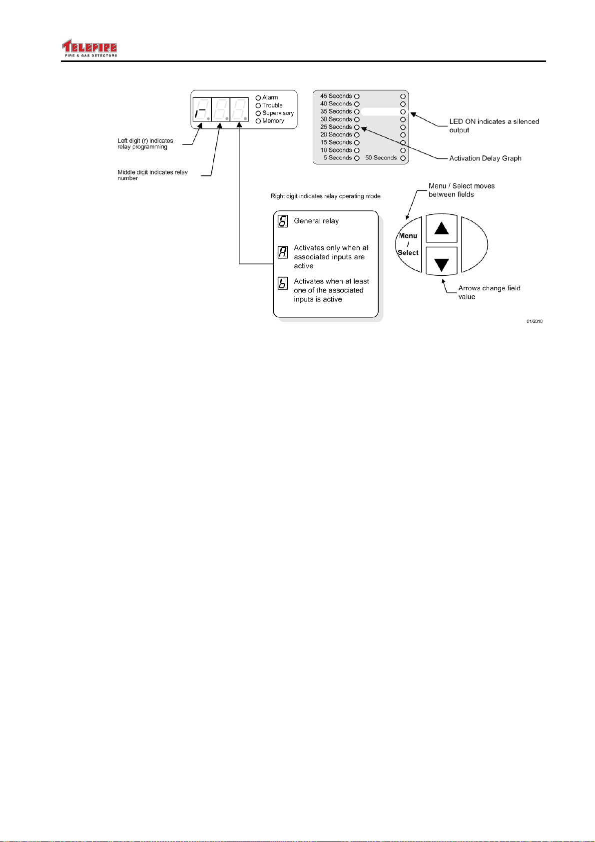
TSA-1000
© 2008 – 2012 Telefire Fire & Gas Detectors Ltd Revision 1.12 האיגש !אצמנ אל הינפהה רוקמ. 2
Figure 26 Display during relay programming
14.11.1 Additional Parameters for General Relays
A relay that is defined as a General relay can be programmed as an Alarm relay, Fault
relay, or Supervisory relay using the LEDs to the right of the digital display.
When selecting an alarm relay we have additional fields to define, the delay field,
"silenced" field, and the matrix field.
• General Alarm relays can be programmed with a delay, and defined as "silenced" or
"not silenced".
• General Fault relays do not have any additional fields.
• General Supervisory relays can be programmed with a delay.
Refer to section 14.5 on page 57 for a detailed explanation of these fields.
14.11.2 Additional Parameters for Logical "And" Relays
A relay that is defined as a Logical "And" relay can be programmed as an Alarm or
Supervisory relay using the LEDs to the right of the digital display.
• Logical "And" Alarm relays can be programmed with a delay, defined as "silenced"
or "not silenced", and the zones that belong to the logical operation.
• Logical "And" Supervisory relays can be programmed with a delay, and the zones
that belong to the logical operation.
Refer to section 14.5 on page 57 for a detailed explanation of these fields.
14.11.3 Additional Parameters for Logical "Or" Relays
A relay that is defined as a Logical "Or" relay can be programmed as an Alarm or
Supervisory relay using the LEDs to the right of the digital display.
• Logical "Or" Alarm relays can be programmed with a delay, defined as "silenced" or
"not silenced", and the zones that belong to the logical operation.
• Logical "Or" Supervisory relays can be programmed with a delay, and the zones
that belong to the logical operation.
Refer to section 14.5 on page 57 for a detailed explanation of these fields.
– Page 60 of 60 –
Page 69
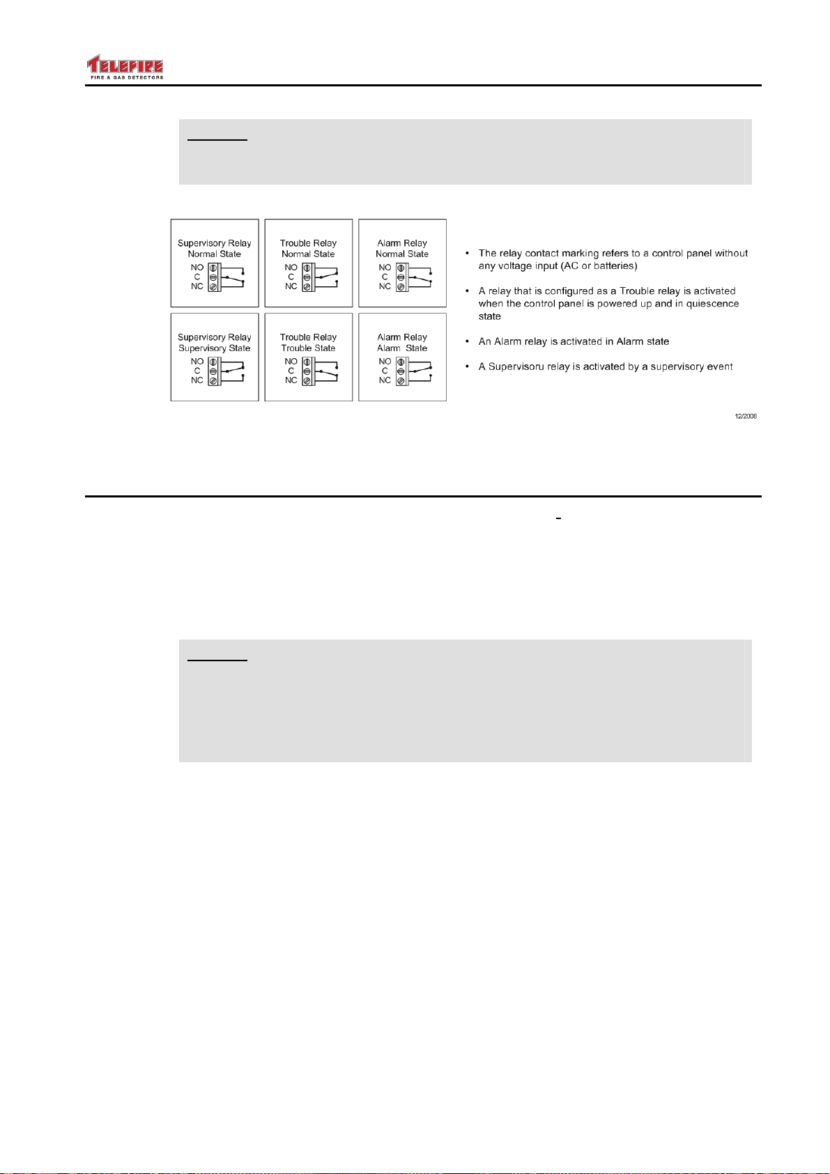
TSA-1000
© 2008 – 2012 Telefire Fire & Gas Detectors Ltd Revision 1.12 האיגש !אצמנ אל הינפהה רוקמ. 2
Note
i
A relay that is defined as a Fault relay will be energized when the system is
powered and in normal state (see diagram below).
Figure 27 Programmable Relay Contacts During Normal Operations and Upon
Activation
14.12 Zone Programming
In zone programming mode the leftmost digit will display i (input), the middle digit
represents the zone number (zones 10 – 16 are represented by the letters A – G
respectively), and the right digit represents the mode of operation as follows:
• d – Represents a standard initiating device zone (detectors, etc.) or supervisory
input. Additional fields can set the verification delay time and verification enabling.
Refer to section 14.5 on page 57 for a detailed explanation of these fields.
• P – Represents manual alarm call points zone
Note
i
• Ξ – Represents a pressure switch input
• A – Represents an Abort switch input
• F – Represents a flow switch input
• h – Represents Hold switch (type 1 as per EN-12094-1)
• H – Represents Hold switch (type 2 as per EN-12094-1)
• ┌┘ – Represents extinguisher mode of operation select switch. When activated, the
Some of the input types may have additional fields such as verification and delay. Refer
to section 14.5 on page 57 for a detailed explanation of these fields.
A push-button input (P) has a higher priority than inputs defined as h (type 1
hold) or H (type 2 hold).
Activating a call-point connected to a type P input will result in release
of extinguishing release even when hold extinguishing (h or H) is
activated.
extinguishing system will react to manual activation only. Extinguishing activation
by detectors and fire call points is disabled.
– Page 61 of 61 –
Page 70
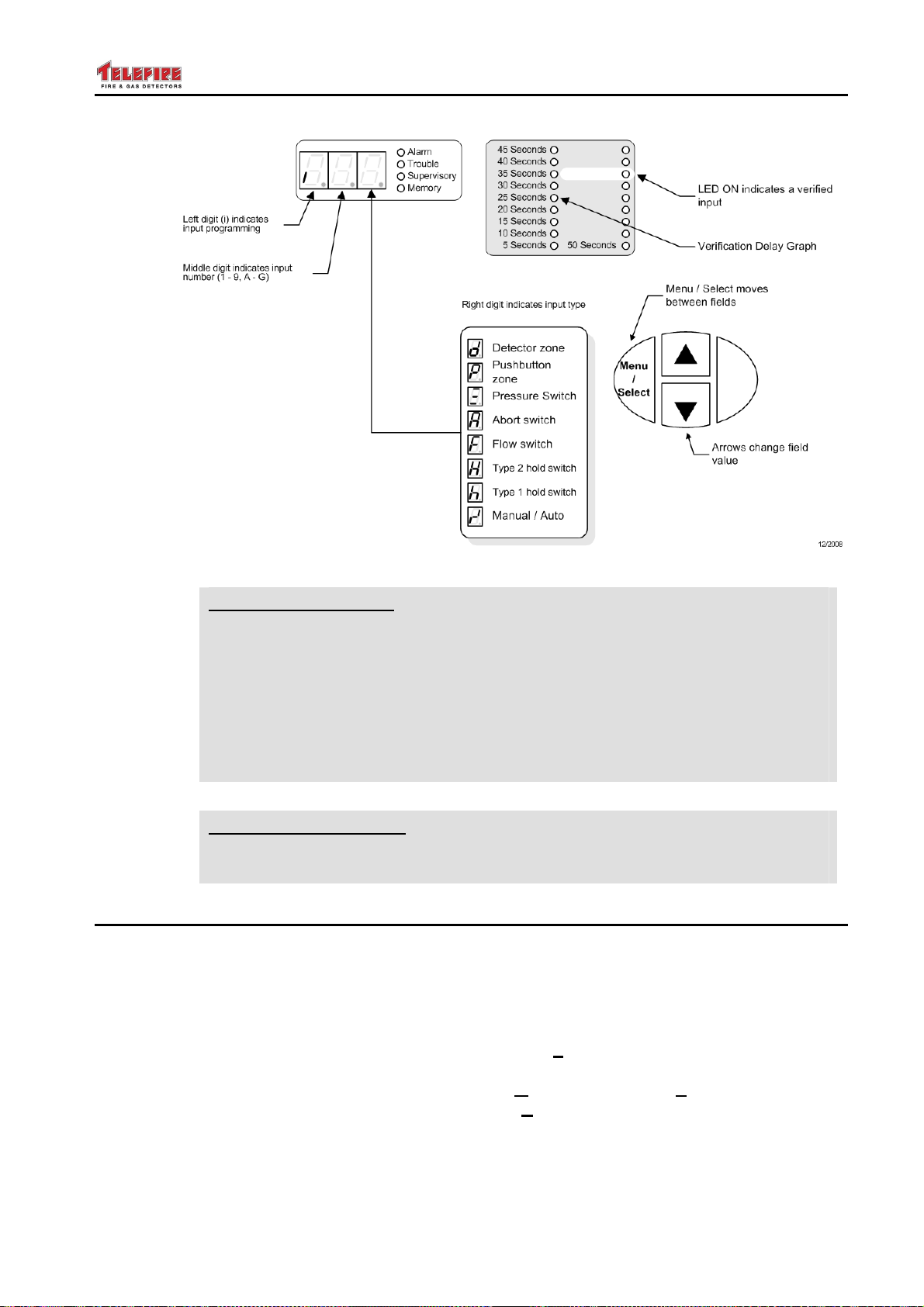
TSA-1000
© 2008 – 2012 Telefire Fire & Gas Detectors Ltd Revision 1.12 האיגש !אצמנ אל הינפהה רוקמ. 2
Figure 28 Display during input programming
CP 10
IS 1220
CP 10 Requirement
CP-10:2005 section 2.5.11 states "the following components shall not be
subject to alarm verification feature:
(a) Alarm zone facilities containing only manual call points
(b) Circuits between sub alarm panels and the main alarm panel
(c) Detectors used to activate fire suppression systems
(d) Detectors installed in high-risk areas
(e) Alarm zone circuits from fire suppression systems".
IS 1220 Requirement
IS 1220 Part 3 does not allow delaying zones that are a part of cross-zone
activation; zones that have heat detectors; and zones that have call points.
14.13 Output Programming
All the system's outputs are programmable and can be configured as either alarm or
supervisory outputs.
The main board contains 4 outputs, numbered 1 – 4 from left to right. Outputs on the
expansion modules are indicated by a LED next to the output's contacts on the
expansion card that is lit when selected.
During output programming the left digit will be o (output). The middle digit represents
the output number (1. – first output, 2. – second output, etc). The rightmost digit
represents the output's operating mode (G – General; A – logical "And" of selected
inputs, b – logical "Or" of selected inputs; E – Extinguishing output).
– Page 62 of 62 –
Page 71
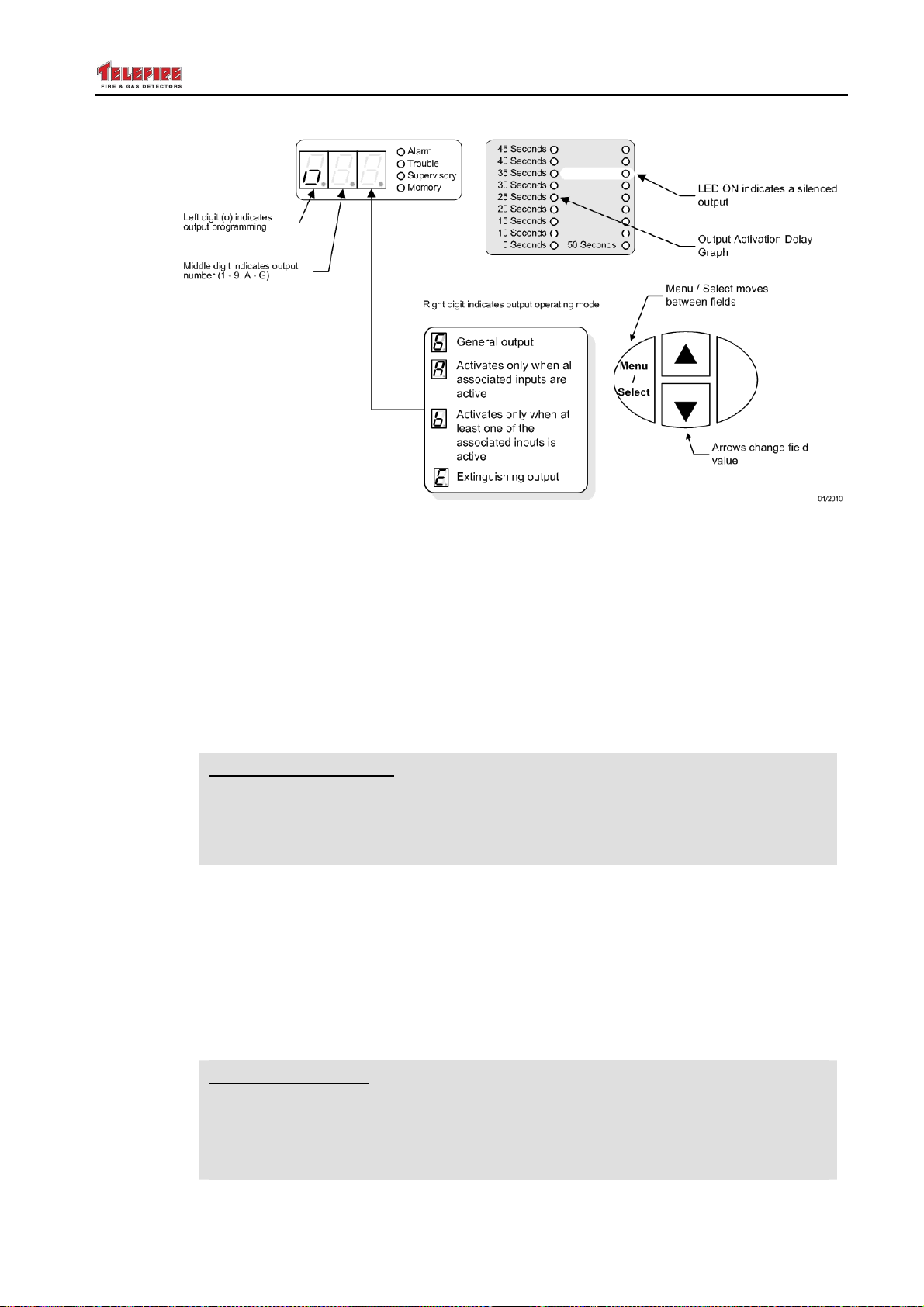
TSA-1000
© 2008 – 2012 Telefire Fire & Gas Detectors Ltd Revision 1.12 האיגש !אצמנ אל הינפהה רוקמ. 2
Figure 29 Display during output programming
CP 10
14.13.1 Additional Parameters for General Outputs
An output that is defined as a General output can be programmed as an Alarm output or
Supervisory output using the LEDs to the right of the digital display.
When selecting an alarm output we have additional fields to define, the delay field,
"silenced" field, and the matrix field.
• General Alarm outputs can be programmed with a delay, and defined as "silenced"
or "not silenced".
• General Supervisory outputs can be programmed with a delay.
Refer to section 14.5 on page 57 for a detailed explanation of these fields.
CP 10 Requirement
CP-10:2005 section 2.5.8 states "no isolation and delay facilities shall be
allowed for the transmission of fire alarm signals to fire alarm sounders".
Programmable outputs that are defined as "silenced" are considered as fire
alarm sounder outputs and can not be disabled.
14.13.2 Additional Parameters for Logical "And" Outputs
An output that is defined as a Logical "And" output can be programmed as an Alarm or
Supervisory output using the LEDs to the right of the digital display.
• Logical "And" Alarm outputs can be programmed with a delay, defined as "silenced"
or "not silenced", and the zones that belong to the logical operation.
• Logical "And" Supervisory outputs can be programmed with a delay, and the zones
that belong to the logical operation.
Refer to section 14.5 on page 57 for a detailed explanation of these fields.
UL 864
– Page 63 of 63 –
UL Requirement
• UL 864 Edition 9 does not allow input zone delay in conjuncture with cross-
zoning.
• UL 864 states that when utilizing more than one zone with verification, the
max verification time shall not exceed 30 seconds
Page 72

TSA-1000
© 2008 – 2012 Telefire Fire & Gas Detectors Ltd Revision 1.12 האיגש !אצמנ אל הינפהה רוקמ. 2
14.13.3 Additional Parameters for Logical "Or" Outputs
An output that is defined as a Logical "Or" output can be programmed as an Alarm or
Supervisory output using the LEDs to the right of the digital display.
• Logical "Or" Alarm outputs can be programmed with a delay, defined as "silenced"
or "not silenced", and the zones that belong to the logical operation.
• Logical "Or" Supervisory outputs can be programmed with a delay, and the zones
that belong to the logical operation.
14.13.4 Additional Parameters for Extinguishing Outputs
An output that is defined as an Extinguishing output can be programmed with a delay
and with the zones that activate it.
Refer to section 14.5 on page 57 for a detailed explanation of these fields.
14.14 Saving Data and Exiting Programming Mode
In order to store the parameters at the end of the programming all system configurations
press the Ack/Prog key for a few seconds until the display will show PPP and a long
beep will sound. If the programming process is successful the system will return to
normal display (the digital display moves the figure 8 from left to right).
The system checks automatically the validity and integrity of the settings and will display
an error message E## (Error ##). Please refer to section 16.4 on page 70.
When trying to exit programming mode without saving by pressing the Reset key, the
system will display nSv (not Saved). This message will be displayed only when
performing changes. Pressing the Reset key a second time will exit the system
programming without any changes. When reviewing the programming without changes,
the exit is without any warnings.
The system stores configuration programming permanently, even when both primary
and secondary power sources are disconnected.
– Page 64 of 64 –
Page 73

TSA-1000
© 2008 – 2012 Telefire Fire & Gas Detectors Ltd Revision 1.12 האיגש !אצמנ אל הינפהה רוקמ. 2
15 Operation and Maintenance
15.1 Evacuation (EVC)
Press the Menu key to enter the main menu. Press the ▲ or ▼ keys until the display
shows EVC. Press the Enter key to activate all general outputs.
In a networked system the digital display will alternately display EVC and the panel
number that has activated the evacuation (P##).
15.2 On / Off Zone or Output (OFF)
Press the Menu key to enter the main menu. Press the ▲ or ▼ keys until the display
shows OFF. Press the Enter key to move the cursor to the device field. Select the
device by pressing the ▲ or ▼ keys. Press the Enter key to toggle the device between
normal and disabled. A disabled device will show u in the right digit.
Press the Ack/Prog key for a few seconds until the display will show PPP and a long
beep will sound. The system will indicate the disabled zone or output on the digital
display (x#u), the Disabled LED in the general display area, and the disabled zone's
Disabled LED in the zone display area,
15.2.1 Keyboard Locking
Keyboard locking prevents system configuration modification by unauthorized personnel,
when the system's keyboard is locked there is no possibility to perform any functions
other than acknowledge an event, paging through memory to display alarm and fault
events.
The system's default configuration is locked keyboard.
When the keyboard is locked the system requests a password to perform any operation.
The system will return to locked keyboard automatically 30 minutes after the last key
press in unlocked condition.
Press the Enter key to toggle between locked (buL – buttons Locked) and unlocked (bu)
keyboard
Note
i
Lock the keyboard after programming or maintaining the system.
15.3 Field Test (ft)
Field test is used for periodic testing of the system by a single person. Field test can be
selected for a single zone or a group of zones.
During field test activation of a device in the selected zones will light the device's alarm
LED, indicate the zone on the control panel by the zone number and alarm LED in the
digital display section. The test will not activate output devices. The system will reset
the activated zone about 15 seconds after activation. An alarm from a zone that was not
selected for testing will immediately activate the fire alarm condition on the panel.
Press the Menu key to enter the main menu. Press the ▲ or ▼ keys until the display
shows Ft. Press the Enter key. Select the zones for testing by using the ▲ or ▼ keys.
Press Enter to select the appropriate zone – the rightmost digit will show t. Press the
Ack/Prog key to start the field test. The system will indicate Field Test mode by
displaying the Test LED in the general display area, the private Test LED in the zone
display area, and – – – on the digital display.
– Page 65 of 65 –
Page 74
TSA-1000
© 2008 – 2012 Telefire Fire & Gas Detectors Ltd Revision 1.12 האיגש !אצמנ אל הינפהה רוקמ. 2
During the test the zone number and the alarm LED will light for 15 seconds. In case of
an alarm or fault events that occur during field test the digital display will indicate them
with a higher priority.
To quit field test and return to normal operation repeat the procedure listed above until
all inputs do not have a t (test) displayed in the rightmost digit.
15.4 Event Log (LOG)
The event log (LOG) menu is used to display or print the alarm and fault event log and
system configuration.
Page through the menus until the display shows LOG. Press Enter. The system will
request the password (PAS). Enter the password (default 2222) and use the
Menu/Select key to page between the fields.
Left Digit Middle Digit Right Digit
Record type
• t – fault event log
• A – alarm event log
• C – system
configuration
Selects language
• E – English
• S – Secondary
language
15.5 Alarm Counter (ALC)
The alarm counter displays the total number of alarms accumulated in the system.
Page through the menus until the display shows ALC. Press Enter. The system will
request the password (PAS). Enter the password (default 2222) and press Enter. The
display will show the alarm count.
15.6 Changing Password (PAS)
This menu is used to change the Operator (access level 2) and Programmer (access
level 3) passwords.
Page through the menus until the display shows PAS. Press Enter. The system will
request the password by blinking PAS. Enter the programmer's password (default 2222)
and press Enter.
The leftmost digit will indicate which password is viewed or modified – Programmer's (P)
or Operator's (O) password. The middle digit represents the digit number (1 – 4), and
the rightmost digit shows the value of that digit (1 – 6). Navigate between the fields by
pressing Menu. Change the field's value by using the ▲ and ▼ keys.
Action (press the
Buzzer/Ack/Prog key to
print or clear the log)
• P – Printing
• c – clear log
15.7 Setting Time and Date (t+d)
This menu is used to set the system's time and date.
Page through the menus until the display shows t┤d (time + date). Press Enter. The
system will request the password (PAS). Enter the password (default 2222) and press
Enter. The leftmost field indicates the hour (h), minute (m), day (d), month (M), and
year (Y). The middle and right digits represent the value of the left field.
To store the modified time and date press the Ack/Prog key for a few seconds until the
display will show PPP and a long beep will sound. The system will return to normal
display (the digital display moves the figure 8 from left to right).
– Page 66 of 66 –
Page 75

TSA-1000
© 2008 – 2012 Telefire Fire & Gas Detectors Ltd Revision 1.12 האיגש !אצמנ אל הינפהה רוקמ. 2
To exit without modifying the time and date press the Reset key, the system will display
nSv (not Saved). This message will be displayed only when performing changes.
Pressing the Reset key a second time will exit without any changes.
15.8 Lamp Test (lt)
Page through the menus until the display shows lt.
Lamp test turns on all LEDs on the panel's keyboard / display and the digital display
shows 8.8.8.. The internal buzzer will also sound. The two dual color LEDs (Telecom
and Sounders) in the general display area will be yellow and then red.
15.9 Additional Information (inF)
The additional information menu shows the system's software version, and total number
of times the system was programmed.
15.10 Restoring Default Configuration (dEF)
This option allows the return to factory default (dEF).
The system requests you to enter the password twice in order to safeguard against
accidental reconfiguration.
15.10.1 Default Configuration
Relays 1 and 2 General Alarm Relay
Relay 3 General Fault Relay
All Inputs Detector zone, unverified
All Programmable Outputs General Alarm, Silenced, no delay
Expansion Modules Not configured (TSA-1000/4)
Remote Annunciators Not configured
Warning
!
All system configuration and programming (including passwords,
activation conditions and matrices) are set back to the factory default
values.
Disconnect all extinguishing devices and other critical activation
outputs before returning to factory default. Reconfigure the panel for
the site's specific requirements and ensure that all input devices are in
normal state and not in alarm and that the activation matrices are
properly configured before reconnecting any extinguishers.
– Page 67 of 67 –
Page 76
TSA-1000
© 2008 – 2012 Telefire Fire & Gas Detectors Ltd Revision 1.12 האיגש !אצמנ אל הינפהה רוקמ. 2
16 Troubleshooting
Note
i
16.1 Maintenance Alert
Photoelectric and multi-sensor smoke detects manufactured by Telefire have unique
physical characteristics that allow them to operate for very long period under normal
operating conditions.
The detectors perform drift compensation automatically as dust residue collects in the
detector until such time that the detector can no longer compensate for the drift. At this
time the detector will indicate the need to clean it by increasing the led flashing
frequency from once every four and a half seconds to twice a second.
The TSA-1000 will indicate the zone with detector and maintenance fault by indicating
the number of the zone in the left and middle digits in the digital display and by
alternating the top and bottom lines in the right digit.
The # symbol in sections to represent the number of the input, output' relay'
expansion module, etc.
16.2 System States
– – –
V #
V # #
# # ┌┘
# # A
# # h
# # H
# # u
# #. u
r # U
16.3 System Faults
Field Test
Zone # verification
Zone ## verification
A manual–only switch was activated in input ##
An Abort switch was activated in input ##
A type 1 hold (h) was activated in input ##
A type 2 hold (H) was activated in input ##
Zone ## disabled
Output ## disabled
Relay # is disabled
A C
d –
d u
d
– Page 68 of 68 –
No input power – AC LED
Open wire on Dialer output
Dialer disabled
י
Short wire on Dialer output
Page 77
TSA-1000
© 2008 – 2012 Telefire Fire & Gas Detectors Ltd Revision 1.12 האיגש !אצמנ אל הינפהה רוקמ. 2
H –
H u
H
V d
V r
# # '
# # –
Open wire on Horn output
Horn output disabled
י
Short wire on Horn output
24Vdc fault
24Vdc (resettable) fault
Short wire on zone #
Open wire on zone #
# # Ξ A pressostat input (Ξ) input was activated on input ##
# #. '
# #. –
# #. |
2 4 i
A # '
A # A
b t –
Short wire on programmable output #
Open wire on programmable output #
Over–current on output ##
Faulty 24V supply from the power supply
Annunciator # is disconnected
Annunciator # is connected, but is not configured
Disconnected battery
b t L
C # –
C # c
C # E
C h –
C H L
C h
C o d
C P r
d A t
d t '
d t –
E #. A
Low battery voltage
Expansion Module # is not connected
Expansion module # – configuration error
Expansion Module # is connected, but is not configured
Charger fault (disconnected)
Low charge
י
Charger fault (short)
Checksum error – return the TSA–1000 to the manufacturer for
repair
Hardware reset (CP 10 version only)
Checksum error on site–specific data. Return the control panel
to the factory default configuration (see section 15.10.1 15.10 on
page 67). Reconfigure the control panel, including input,
outputs, and activation matrices.
FWRE output is shorted
FWRE output is open
Extinguishing output # activated.
This display remains even after control panel reset to
ensure replacement of extinguishing agent. To clear this
status enter programming mode and return to normal after
a few seconds.
– Page 69 of 69 –
Page 78
TSA-1000
© 2008 – 2012 Telefire Fire & Gas Detectors Ltd Revision 1.12 האיגש !אצמנ אל הינפהה רוקמ. 2
i
E E P
G F –
G F ┤
Note
Ground leakage faults may affect output fault display. Resolve the ground
fault issues first.
EPROM failure – return to manufacturer for repair
Ground fault – negative wire leakage
Ground fault – positive wire leakage
16.4 Programming Faults
# E
E r r
E 0 1
E 0 2
E 2 0
Extra Device – a control panel exists in the network but is not
defined as a Sub Panel
Wrong password
Expansion module configuration error
The expansion module that is installed is not the type that was
configured
Zone definition error
E 2 1
E 4 0
E 4 1
E 4 2
E 4 3
E 4 4
E 4 5
E 4 6
Non-consecutive zone number (e.g., an expansion module was
configured as zones 6 – 13 instead of 5 – 12)
An output was defined as neither an alarm nor a supervisory
output
An extinguishing output was defined as a supervisory output
A supervisory output is defined without supervisory inputs
Output configuration error
Non-consecutive output number (e.g., an expansion module
was configured as outputs 6 – 13 instead of 5 – 12)
A supervisory matrix configuration error:
• A supervisory output matrix includes alarm or trouble inputs
• A supervisory output has no supervisory inputs
• An "And" (A) supervisory output has less than 2 inputs
• An Or (b) supervisory output does not include any inputs
An alarm or extinguishing matrix configuration error:
• An alarm output matrix includes supervisory or trouble
inputs
• An extinguishing output matrix includes trouble inputs
• An alarm or extinguishing output has no alarm inputs
• An "And" (A) alarm output has less than 2 inputs
• An Or (b) alarm output does not include any alarm inputs
– Page 70 of 70 –
Page 79
TSA-1000
© 2008 – 2012 Telefire Fire & Gas Detectors Ltd Revision 1.12 האיגש !אצמנ אל הינפהה רוקמ. 2
E 6 0
E 6 1
A relay was defined without defining output type
Non-consecutive relay number (e.g., an expansion module was
configured as relays 5 – 7 instead of 4 – 6)
E 6 2
A relay was defined as a supervisory output, but no supervisory
input was defined
E 6 3
E 6 4
E 6 5
Wrong definition of alarm relay
A supervisory relay is defined without supervisory inputs
A relay matrix is defined without inputs
n S v Not Saved – the programming modification was not saved to
permanent memory
– Page 71 of 71 –
Page 80

TSA-1000
© 2008 – 2012 Telefire Fire & Gas Detectors Ltd Revision 1.12 האיגש !אצמנ אל הינפהה רוקמ. 2
17 Commissioning
• Verify that ALL POWER SOURCES are disconnected.
• Verify that THE EXTINGUISHER IS DISCONNECTED (disconnect both wires to the
extinguisher), connect a DUMMY load to the extinguisher output.
• Verify that all required interfaces are connected. Verify correct wiring.
• Verify presence and connection of required (ONLY) and correct EOL resistors.
• Connect mains and battery.
• Fix all faults
• When ALL faults are fixed and the ECD is in the quiescent state, configure and
program the ECD as required.
• Update site specific data and date and time
• Change the level 2 and 3 passwords (Recommended).
• Verify that the POWER LED is ON with short OFF pulses
• Perform a full Field Test,
• Perform an activation test.
• Test and verify correct operation from detectors and from manual activation
• Verify that the ECD lock and switch keys are available and accessible to operators
• Attach the required documentation to or near the Control Panel
• Disconnect ALL power, Remove the dummy load, and connect the extinguisher to
the extinguishing output or output lines.
• Connect mains and batteries.
• Fix all problems
• Verify that the ECD is in the quiescent state.
Note
i
Do not access, probe, or touch the area near the AC input terminals when the
CP is powered, to avoid electric shock.
17.1.1 Additional System Documentation
In different countries and according to some CP installation regulations, it is sometimes
required to place a document containing condensed system information and operating
instructions, on or near the CP.
Attach the condensed instructions document to the system’s front panel, or frame it and
place it in a prominent, highly visible position nearby.
It is recommended that the document shall at least contain the following;
• Actions to be taken upon events of alarm or fault by the operators
• A list of areas/zones as installed in the protected premises, and blank spaces for
their details and description
• Text referring to The name, address and phone number of the service
representative, and blank spaces to fill in the details after installation
• Text referring to the name, address and phone number of the Installing
representative, and blank spaces to fill in the details after installation.
– Page 72 of 72 –
Page 81

TSA-1000
© 2008 – 2012 Telefire Fire & Gas Detectors Ltd Revision 1.12 האיגש !אצמנ אל הינפהה רוקמ. 2
• Document issue number and date
• If the document is not attached to the CP front panel, a note at the bottom stating
that it shall be framed and placed near the CP for ready reference.
A sample form is attached at the end of this manual.
– Page 73 of 73 –
Page 82

TSA-1000
© 2008 – 2012 Telefire Fire & Gas Detectors Ltd Revision 1.12 האיגש !אצמנ אל הינפהה רוקמ. 2
18 Maintenance
No specific maintenance is required for the TSA1000.
Keep the TSA1000 clean and dry. If necessary, clean the outside of the enclosure with a
slightly damp cloth.
The batteries should be tested and replaced according to the instructions of the battery's
manufacturer.
If the batteries show any signs of swelling, leakage or corrosion, or the ECD indicates a
battery fault, replace with a new set.
Maintenance routine:
Verify that the field wires are fully inserted into the TB, and no wires are broken.
Tighten the TBs, if necessary
Verify ECD is in the quiescent condition
– Page 74 of 74 –
Page 83
TSA-1000
© 2008 – 2012 Telefire Fire & Gas Detectors Ltd Revision 1.12 האיגש !אצמנ אל הינפהה רוקמ. 2
19 Routine Testing
The TSA-1000 shall be tested weekly as specified in the next paragraph.
The system should be fully tested at least twice a year, or as required by national and/or
local fire codes. All devices, system wiring and component functions should be tested
and maintained. These inspections should be performed in addition to the routine
maintenance activities such as cleaning the detectors (which should be performed in
accordance with Telefire’s instructions).
Perform a Field Test of each zone.
Maintenance and test actions shall be conducted by a company or service technician
authorized by Telefire.
Records of all inspection and maintenance activities should be kept.
Note
i
19.1 Weekly Inspection – To Be Performed by Site Personnel
The site's safety supervisor should inspect the control panel weekly and verify that all of
the following conditions exist:
• The green LED is on and is not blinking
• None of the yellow or red LEDs are on or blinking
• The control panel's fault buzzer does not sound
• The digital display moves the figure 8 from left to right
Call your service representative if any of these conditions is not met
Testing shall be performed by authorized service personnel that are
employed by authorized companies.
– Page 75 of 75 –
Page 84

TSA-1000
© 2008 – 2012 Telefire Fire & Gas Detectors Ltd Revision 1.12 האיגש !אצמנ אל הינפהה רוקמ. 2
20 Certification
Telefire’s TSA-1000 Conventional Multi-Zone Fire Alarm and Extinguishing Control
Panel has the following approvals:
• EN 54-2 and EN 54-4 Certified
• SI 1220 Certified
• GOST 53325-2009 Certified
• CE Marked
• UL 864 edition 9 Compliant
– Page 76 of 76 –
Page 85
TSA-1000 Instructions for Immediate Action
Normal
Alarm Condition
Action
Silencing
Return to
Normal Operation
from Alarm
Automatic
Extinguishing
Fault Condition
Action
Silencing
"Power" LED is ON and the digital display scrolls a figure 8 from
left to right.
"Alarm" LEDs, internal buzzer and the Alarm Sounder are ON.
Take appropriate actions in accordance with the pertinent
instructions at your site, and notify the relevant entities.
To silence the Alarm Sounder press
After taking the actions detailed above, restore the system to
normal operation by pressing the "
Extinguishing is performed automatically, without human
intervention (Except for triggering by Manual Release).
After the extinguishing pulse ends, the TSA-1000 enters the
"Extinguishing Fault" state.
Call the service representative listed below if the extinguishers
were activated, to replenish the extinguishant, restore extinguishing
capability and return to normal operation.
The General and specific "
buzzer sounds.
Take appropriate actions in accordance with the pertinent
instructions at your site.
Resolving the fault will automatically restore the system to normal
operating conditions.
To silence the internal buzzer press the "
Fault
"Silence/Resound" key.
Reset
" LEDs turns on, and the internal
" key.
Buzzer Off"
key.
Please refer to the TSA-1000 Technical Manual for further details.
Zone
Description
Zone
Description
1 9
2 10
3 11
4 12
5 13
6 14
7 15
8 16
Service Representative Name:___________Address:________________________________
Phone_________________ ______________________________________________________
Installing Representative: Name _____________Address:_____________________ ________________
Phone:__________ _____________________________________________________________________
This document shall be framed, details filled, and placed adjacent to the control unit
TSA-1000 Instructions for Immediate Use Version 1.01 December 2011
 Loading...