

Page 1
Control Panels
ADR-7000 / SAVER-7000 /
GUARD-7
Addressable
Fire Alarm Control Panel
Technical Manual
TELEFIRE FIRE & GAS DETECTORS LTD
PO Box 7036
Petach Tikva 49250
Israel
ADR-7000En 98.pdf
Revision 0.98
October 2017
Page 2

i
Note
The terms “Trouble” as used in NFPA 72 guideline and UL standards and
“Fault” as used in EN 54 standards are used interchangeably throughout this
manual.
i
Note
Do not install, operate, and maintain this ADR-7000 before fully reading this
manual.
© 2017 – 2017 Telefire Fire & Gas Detectors Ltd.
Page 3

ADR-7000 / SAVER-7000 / GUARD-7
© 2017 – Telefire Fire & Gas Detectors Ltd Revision 0.98 October 2017
Table of Contents
1 INTRODUCTION ............................................................................................ 1
1.1 SAVER-7000 AND GUARD-7 DIFFERENCES ................................................... 2
2 ADR-7000 CONTROL PANELS .................................................................... 3
2.1 MAIN BOARD – ADR-7021 .............................................................................. 4
2.2 SLC LINE CARD – ADR-7002 ......................................................................... 4
2.3 KEYBOARD AND DISPLAY MODULE – ADR-7003 .............................................. 5
2.4 POWER SUPPLY ............................................................................................. 5
2.5 ZONE ALARM MODULE – ADR-7000ZM .......................................................... 5
2.6 NETWORK COMMUNICATION MODULE – LON-7000 .......................................... 5
2.7 TCP/IP MODULE – NET-7000 ........................................................................ 6
2.8 LOOP EXPANSION CARD – ADR-7001EM1 – ADR-7000 ONLY ......................... 7
2.9 REMOTE ANNUNCIATOR – RM-7000 ................................................................ 7
2.10 ACCESS LEVELS ............................................................................................ 8
3 WORK STATES – ALARM, FAULT, SUPERVISORY, DISABLEMENT,
AND TEST MODES ..................................................................................... 10
3.1 NORMAL (QUIESCENCE) STATE ..................................................................... 10
3.2 ALARM STATE .............................................................................................. 10
3.3 FAULT STATE ................................................................ ............................... 12
3.4 SUPERVISORY STATE ................................................................................... 12
3.5 DISABLEMENT STATE ................................................................................... 13
3.6 TEST STATE................................................................................................. 14
3.7 STATUS STATE ............................................................................................ 14
4 INSTALLATION ................................................................ ........................... 15
4.1 PRE-INSTALLATION PLANNING ....................................................................... 15
4.2 CABLE PLANNING ......................................................................................... 17
4.3 WIRING ....................................................................................................... 21
4.4 INSTALLATION OF DETECTORS, I/O MODULES, AND OTHER MODULES ............. 21
4.5 POST-INSTALLATION ..................................................................................... 27
5 AUTOMATIC EXTINGUISHING ................................................................... 30
5.1 EXTINGUISHING OUTPUT AND EXTINGUISHING CONTROLLER ........................... 30
5.2 MANUAL ACTIVATION .................................................................................... 30
5.3 EXTINGUISHING DELAY ................................................................................. 30
5.4 EXTINGUISHING DISCONNECT ....................................................................... 31
5.5 EXTINGUISHING NOTIFICATION AND ACTION TO PERFORM AFTER RELEASE ...... 31
— I —
Page 4

ADR-7000 / SAVER-7000 / GUARD-7
© 2017 – Telefire Fire & Gas Detectors Ltd Revision 0.98 October 2017
6 DISPLAY AND KEYBOARD ........................................................................ 33
6.1 LCD DISPLAY .............................................................................................. 33
6.2 LEDS .......................................................................................................... 34
6.3 OPERATOR KEYS ......................................................................................... 36
6.4 NUMERICAL AND ARROW KEYS ................................................................ ..... 37
7 SYSTEM CONFIGURATION (PROGRAMMING) PROCESS ...................... 38
7.1 MENU STRUCTURE ....................................................................................... 38
7.2 ENTERING CONFIGURATION STATE ............................................................... 39
7.3 CONFIGURATION PROCESS ........................................................................... 39
7.4 SAVING THE CONFIGURATION AND EXIT OUT OF SYSTEM CONFIGURATION ...... 39
8 SYSTEM CONFIGURATION (PROGRAMMING) ........................................ 41
8.1 SYSTEM CONFIGURATION ............................................................................. 41
8.2 ENABLEMENT / DISABLEMENT ....................................................................... 42
8.3 MONITOR ..................................................................................................... 44
8.4 SYSTEM REPORTS ....................................................................................... 44
8.5 UTILITIES ..................................................................................................... 48
8.6 WALK TEST ................................................................................................. 51
8.7 SYSTEM VIEW .............................................................................................. 53
8.8 SMOKE CONTROL TEST ................................................................................ 54
8.9 SYSTEM CONFIGURATION ............................................................................. 54
8.10 DEVICE PROGRAM ....................................................................................... 61
8.11 CREATING DEVICE GROUPS .......................................................................... 64
8.12 DIAGNOSTICS .............................................................................................. 64
8.13 CLEAR REPORTS.......................................................................................... 64
8.14 CHANGE PASSWORDS .................................................................................. 65
8.15 ADVANCED .................................................................................................. 65
8.16 DETECTOR INITIALIZATION ............................................................................ 65
9 TROUBLESHOOTING ................................................................................. 67
9.1 LEDS .......................................................................................................... 67
9.2 CONTROL PANEL ERROR MESSAGES ............................................................ 67
9.3 SYSTEM FAULTS .......................................................................................... 67
9.4 ADDRESSABLE DEVICE FAULTS ..................................................................... 69
9.5 PROGRAMMING FAULTS ................................................................................ 71
9.6 STATUS MESSAGES ..................................................................................... 73
9.7 CONTROL PANEL NETWORK FAULTS ............................................................. 73
— II —
Page 5

ADR-7000 / SAVER-7000 / GUARD-7
© 2017 – Telefire Fire & Gas Detectors Ltd Revision 0.98 October 2017
10 PERIODIC TESTS ........................................................................................ 74
10.1 WEEKLY TEST – DONE BY SITE SUPERVISOR ................................................. 74
10.2 BATTERY TEST............................................................................................. 74
11 WARNINGS AND LIMITATIONS ................................................................. 75
12 COMPATIBILITY .......................................................................................... 76
12.1 INPUT DEVICES ............................................................................................ 76
12.2 OUTPUT MODULES ....................................................................................... 76
12.3 UL LISTING .................................................................................................. 77
13 SPECIFICATION .......................................................................................... 78
13.1 GENERAL SPECIFICATION ............................................................................. 78
13.2 POWER SUPPLY ........................................................................................... 78
13.3 REMOTE ANUNCIATORS ................................................................................ 78
13.4 MAIN BOARD – FIELD CONNECTION ............................................................... 78
13.5 MAIN BOARD – RELAYS ................................ ................................................ 79
14 CERTIFICATION .......................................................................................... 80
APPENDIX A – CURRENT CONSUMPTION AND BATTERY CAPACITY
CALCULATION ............................................................................................ 81
WHEN ARE AUXILIARY POWER SUPPLIES NEEDED? ................................................... 84
APPENDIX B – DETECTOR SENSITIVITY SELECTION .................................. 85
14.1 SMOKE DETECTOR SENSITIVITY SETTINGS .................................................... 85
14.2 HEAT DETECTOR SENSITIVITY SETTINGS ....................................................... 85
14.3 MULTI-SENSOR DETECTORS SENSITIVITY SETINGS ........................................ 85
APPENDIX C – STANDARDS COMPLIANCE ................................................... 86
14.4 UL 864 COMPLIANCE ................................................................................... 86
14.5 EN 54 – OPTIONS WITH REQUIREMENTS ....................................................... 86
14.6 EN 12094-1 COMPLIANCE ............................................................................ 87
14.7 CP-10 ......................................................................................................... 87
— III —
Page 6
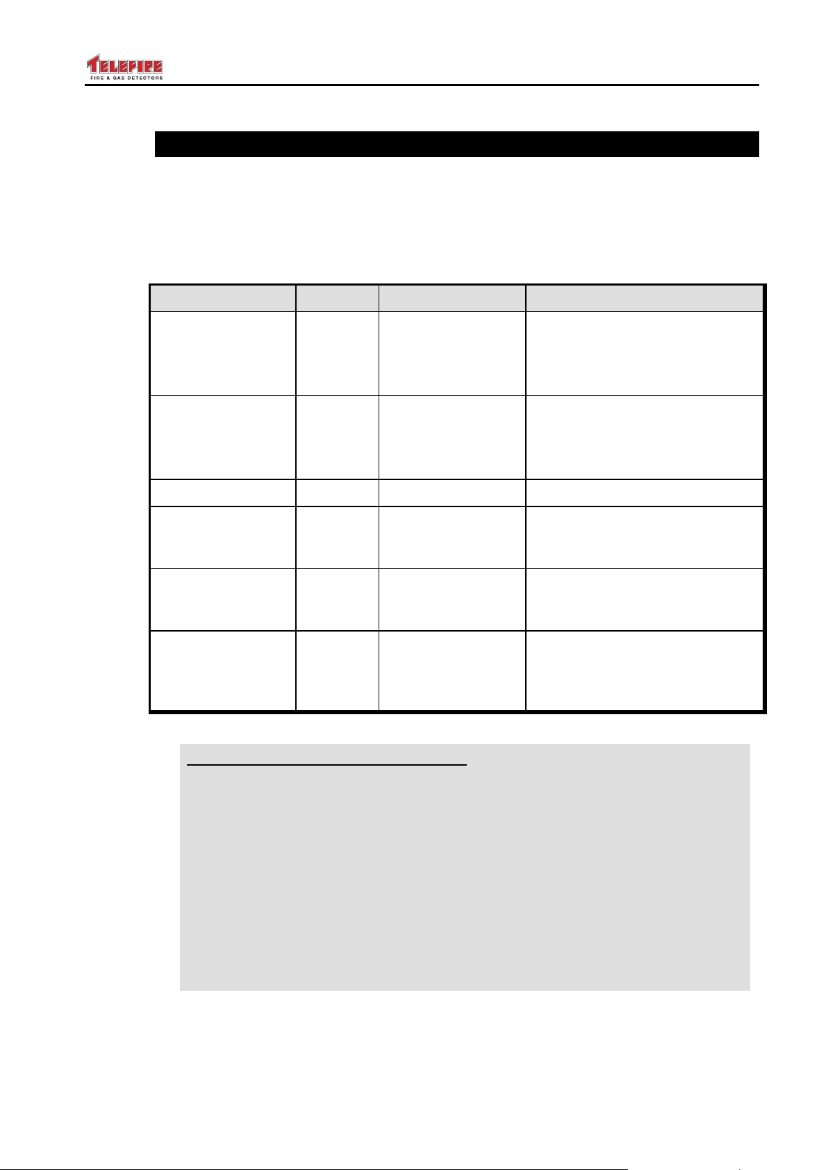
ADR-7000 / SAVER-7000 / GUARD-7
Parameter
Allowed?
Possible Range
Range per UL 864
Alarm verification
by delayed
confirmation
Yes
0-50 seconds
0-60 seconds
Do not combine time-based
alarm verification and cross
zone alarm verification
Alarm verification
by cross-zone
Yes
Cross zone or no
verification
Cross zone or no verification
Do not combine time-based
alarm verification and cross
zone alarm verification
Delay of releasing
Yes
0-50 seconds
0-60 seconds
Delay of first fault
in an addressable
device
Yes
0-240 seconds
0-180 seconds
Delay of buzzer
notification of loss
of AC power
Yes
0-240 minutes
0-3 minutes (0-180 seconds)
Keyboard locking
Yes
Continuously; after
10 minutes; after
30 minutes; after
an hour
0-30 minutes
UL
UL 864 paragraph 59.1 Compliance
The following products mentioned in this manual were not tested or listed by
UL and should not be installed where UL listing is required:
TFH-280A and TFH-220A (Heat Detectors)
ADR-812A and ADR-818A (Input modules)
ADR-828A (LED Driver)
TPS-34A (auxiliary power supply)
TIP-224A (Sounder)
ADR-833A (Extinguishing controller)
TPH-482A and TPH 442A (photo / heat multi-sensor detectors)
Use a UL listed equivalent product where required.
© 2017 – Telefire Fire & Gas Detectors Ltd Revision 0.98 October 2017
UL 864 Compatibility
Telefire's ADR-7000 product line complies with the requirements of several standards,
including UL 864, IS 1220, EN 54, EN 12094, and GOST, and may comply with options
or requirements of one of the standards and are not compliant with another standard.
Where the control panel allows setting of a parameter that are outside the range of one
of the standards, we included an appropriate warning in the relevant area of the manual.
— IV —
Page 7

ADR-7000 / SAVER-7000 / GUARD-7
© 2017 – Telefire Fire & Gas Detectors Ltd Revision 0.98 October 2017
1 Introduction
Telefire's ADR-7000 Advanced Addressable Control Panel is a UL 864 compliant system
that can be used as a standard fire detection and alarm system including sprinkler
supervision; fire detection and extinguishing release system; fireman phone system; a
compliant smoke control.
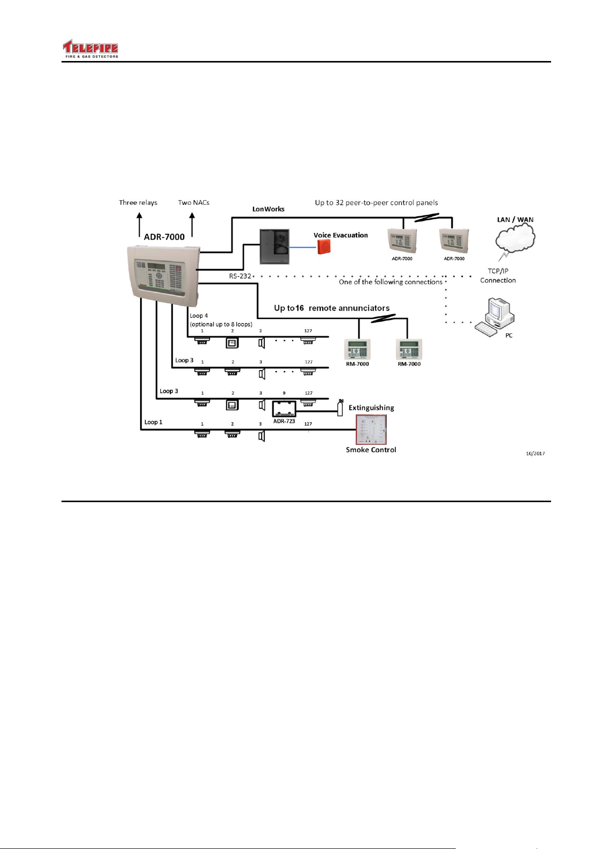
The ADR-7000 control panel monitors addressable initiating devices such as smoke
detectors; heat detectors; manual fire alarm call points; and flow switches. It also
monitors and activates output devices such as sounders; strobes; indicating signs; etc.
The base control panel is modular and can be configured with 1, 2, 3, or 4 Class A or
Class B loops. An expansion module allows extending the system by up to 4 additional
loops (8 loops in total). The ADR-7000 includes two reversed-polarity notification alarm
circuits (NACs) and three programmable dry contact Form C relays; 24Vdc outputs to
devices that require additional 24Vdc supply are also included.
Up to 32 ADR-7000 control panels can be networked in a single peer-to-peer network.
Each control panel is capable to communicate with up to 16 RM-7000 digital
annunciators via an RS-485 interface.
The ADR-7000 has a built-in 150W power supply. Auxiliary 24Vdc to devices is
expandable to hundreds and even thousands of watts using UL listed power supplies
that can be distributed to avoid costly power losses over long cables.
All inputs and outputs are fully supervised. Outputs are monitored for over-current and
are disconnected automatically when the current drawn from them exceeds the specified
amount.
Input and output protection is done without the use of fuses, using an advanced current
management that allows for high resilience of the system when encountering a shorted
output and automatic return to normal operation when the short is resolved.
Telefire's ADR-7000 has a highly resilient power supply system, ensuring that a short on
any input or output (including those located on SLC-connected I/O modules) affects only
the specific point, and does not disable all devices that feed from the same 24Vdc
supply.
It is possible to connect conventional initiating devices to the system via addressable
input (monitor) modules. Conventional output devices may be connected via
addressable NAC output modules.
Strobes connected to NAC outputs are synchronized at the control panel level (i.e., all
strobes connected to an ADR-7000 are synchronized, regardless of the loop they are
connected to). Strobes can be connected without protocol (i.e., two NACs activate
separately the sounders and the strobes), or with protocol (i.e., a single pair of wires
from the NAC to the sounder/strobe control both sounder and strobe via protocol). The
ADR-7000 supports both Wheelock and Gentex protocols.
Every device in the system is individually monitored and controlled for all parameters
such as day and night alarm sensitivity, pre-alarm, operation mode (quiescence, alarm,
fault, and maintenance mode).
The control panel performs automatic drift compensation to adjust the detectors
sensitivity and compensate for changes due to changes in environmental conditions and
dust accumulation. The ADR-7000 includes a maintenance fault feature that alerts the
user when a detector requires cleaning.
Detailed LED indication and a user-friendly graphic LCD provide clear display of the
system's status.
– Page 1 of 87 –
Page 8
ADR-7000 / SAVER-7000 / GUARD-7
© 2017 – Telefire Fire & Gas Detectors Ltd Revision 0.98 October 2017
Each event is clearly detailed and allows for a quick and convenient identification of
alarms and faults to the end user, installer, and service technicians. Optional modules
allow for zone indication.
All configuration programming may be done via the built-in keyboard or with Telefireproprietary PC-based software. The ADR-7000's sophisticated microprocessor allows
easy configuration and modification in the field without the use of dedicated tools, while
providing access only to authorized personnel.
Figure 1 Typical ADR-7000 System
1.1 SAVER-7000 and GUARD-7 Differences
The SAVER-7000 is similar to the ADR-7000, but is stand-alone and can only have 2
loops and up to 3
RM-7000 remotes
The GUARD-7 is a stand-alone control panel that is limited to 60 addresses and can
only have 2 loops and up to 3 RM-7000 remotes
– Page 2 of 87 –
Page 9

ADR-7000 / SAVER-7000 / GUARD-7
© 2017 – Telefire Fire & Gas Detectors Ltd Revision 0.98 October 2017
2 ADR-7000 Control Panels
The ADR-7000 control panel provides user-friendly operation. The keyboard and the
display that are mounted on the front panel contain an illuminated 260-by 64 pixel
graphical LCD, LED indicators for major events, and functional keys. Access to all
operations is secured by multi-level passwords.
The interior section of the cabinet is secured by a key-lock. It contains a power supply,
the main board, line card(s), battery compartment space, and optional communication
modules.
The ADR-7000’s main board can contain one to four ADR-7002 line cards, enabling
control of as many as 508 addressable initiating devices, notification appliances and I/O
modules. Each line card can be configured as a Class B or Class A loop.
An optional expansion modules allows the installation of up to four additional
ADR-7002 line cards (up to 1,016 addresses per control panel).
The system can be expanded beyond the base control panel by networking. An optional
LON-7000 network communication module allows the connection of as many as 32
control panels to set up a peer-to-peer network. With appropriate programming each
control panel on the network is able to respond to alarm and trouble events that occurred
in other control panels.
The control panel has an integral real time clock and calendar that enables day and
night sensitivity setting for each addressable detector according to weekly operation
schedule and working hours. Daytime and nighttime hours can be programmed
independently for each day of the week, as well as national holidays.
Events such as alarm, trouble, silencing, reset, programming, etc., are stored in the
ADR-7000’s memory in the order in which they occur, creating event-list history. An
event record contains date, time, device type, and additional details. Event records can
be displayed on screen and printed as a report.
All operations and configuration can be performed either from the system’s front panel or
from a PC. Telefire’s user-friendly proprietary programming and control software
(running on Windows™ operating system) allows operators/installers to easily configure
any system parameter using its advanced graphical interface.
ADR-7000 control panel for a variety of communication interfaces that allow control and
monitoring;
RS 232 connection to a computer, NET-7000 TCP/IP module for control and
monitoring via a local (LAN) or global (WAN) area network
RS-485 for Class B or Class A connection to remote annunciators
USB connector for connecting to a computer
– Page 3 of 87 –
Page 10
ADR-7000 / SAVER-7000 / GUARD-7
Line Cards
Max. Addresses
Line Cards
Max. Addresses
1
127
5
635
2
254
6
762
3
381
7
889
© 2017 – Telefire Fire & Gas Detectors Ltd Revision 0.98 October 2017
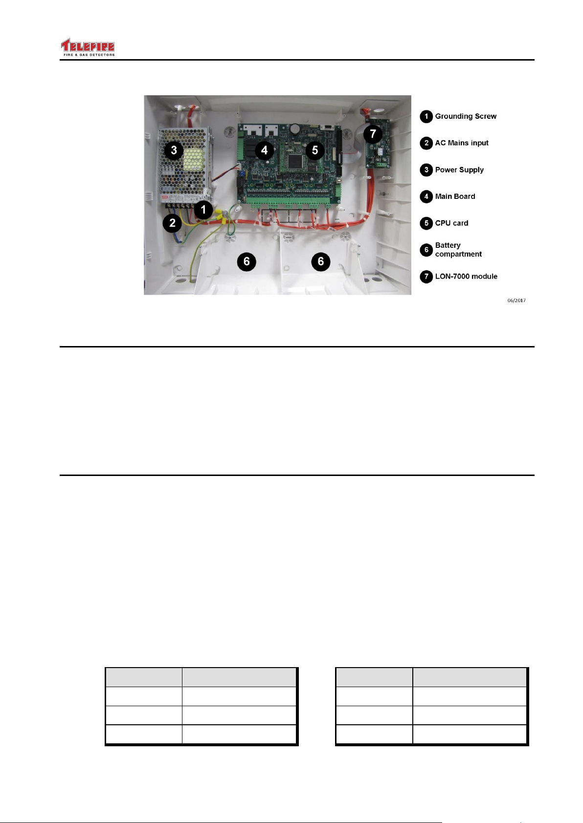
Figure 1 Schematic ADR-7000 subassemblies
2.1 Main Board – ADR-7021
The ADR-7000's ADR-7021 main board is designed for ease of installation and
maintenance. Connectors are located in logical groups; on the left are the input from the
power supply and battery connection; three dry contact relays; and a connector for
changing the addresses of addressable modules. On the bottom are the two general
purpose NACs; SLC loops; 24Vdc supply to the field; and dialer activation and voltage
supply. On the right are the display / keyboard connector; LON-7000 networking
module; an RS-232 port for NET-7000 TCP/IP module, and a connector for the remote
annunciator units.
2.2 SLC Line Card – ADR-7002
Up to four ADR-7002 line cards line cards are mounted on the ADR-7021 main board
and control the bi-directional communication between the control panel and the
addressable devices on the SLC loop.
The loop is electronically protected against shorts, and will be automatically
disconnected if a short is sensed. Each line card can be configured to work in a Class B
or Class A loop.
Two LEDs for each loop indicate loop condition and serve installers and technicians:
The red LED flashes each time a device is addressed
The yellow LED flashes when a fault is detected, even after a momentary
interference that would not activate a trouble condition
– Page 4 of 87 –
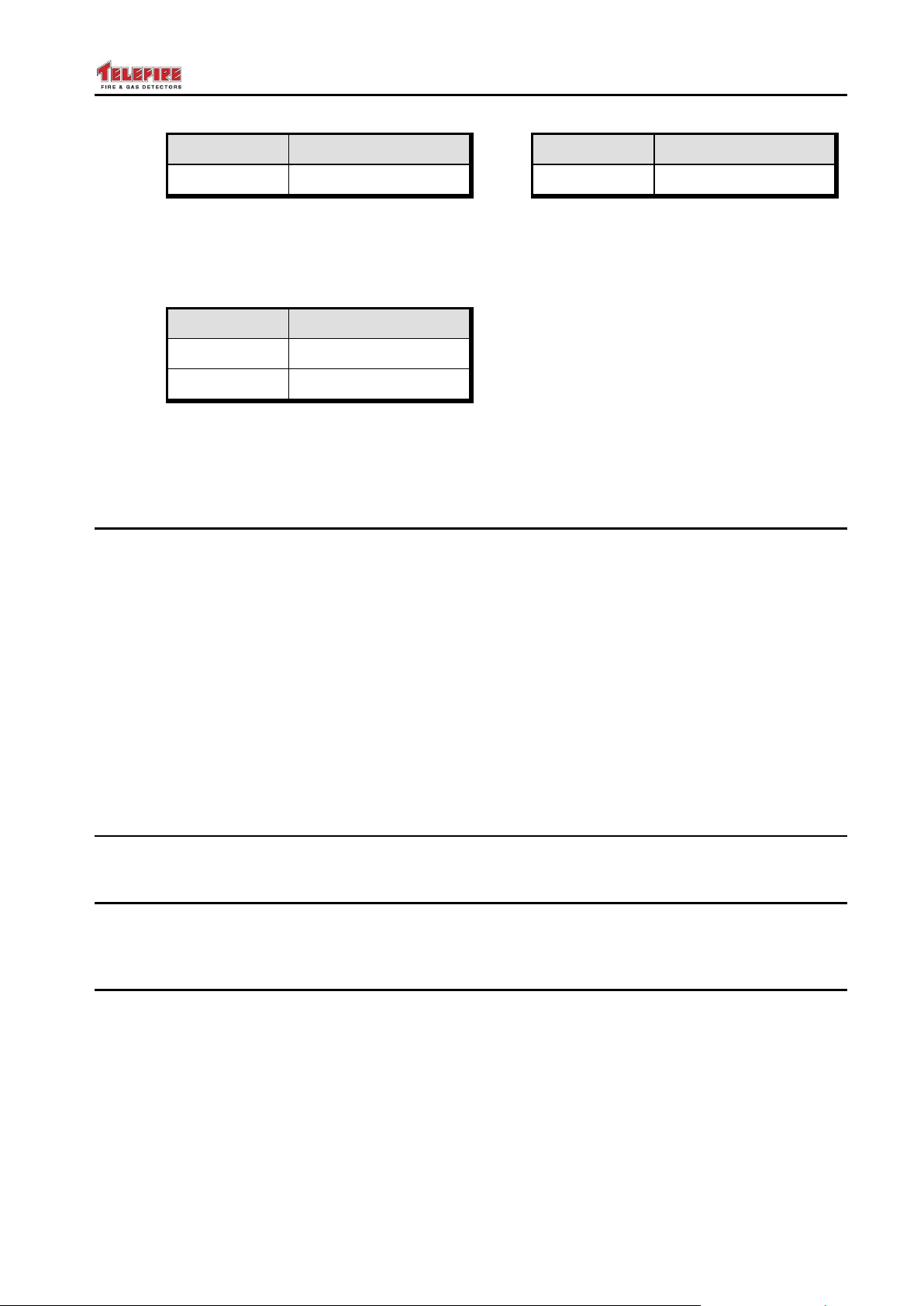
2.2.1 Maximum Addresses – ADR-7000
All loop cards are capable of communicating with up to 127 addresses, and the
maximum number of addresses is a 1,016 single control panel.
Page 11
ADR-7000 / SAVER-7000 / GUARD-7
Line Cards
Max. Addresses
Line Cards
Max. Addresses
4
508
8
1,016
Line Cards
Max. Addresses
1
127
2
254
© 2017 – Telefire Fire & Gas Detectors Ltd Revision 0.98 October 2017
Table 1 Maximum addresses by configuration – ADR-7000
2.2.2 Maximum Addresses – SAVER-7000
All loop cards are capable of communicating with up to 127 addresses, and the
maximum number of addresses is a 254.
Table 2 Maximum addresses by configuration – SAVER-7000
2.2.3 Maximum Addresses – GUARD-7
The GUARD-7 has 60 addresses.
2.3 Keyboard and Display Module – ADR-7003
The keyboard and display module contains a graphic LCD display (240 x 64 pixels),
indicating LED display, and keys for programming and operation. The display and
keypad meet the strict standards of UL 864, EN 54, and IS 1220.
The display and keypad have six main areas:
Graphic LCD display
General display area
Fault display area
Additional indication area
Keyboard
Zone indication LEDs
See detailed explanations on page 22.
2.4 Power Supply
The ADR-7000 has a 150W power supply that accepts 110-240Vac (nominal) input.
2.5 Zone Alarm Module – ADR-7000ZM
The optional Zone Alarm Module may be installed in the ADR-7000 to visually indicate
zones in alarm.
2.6 Network Communication Module – LON-7000
– Page 5 of 87 –
The LON-7000 is a communication module that enables connection between control
panels to establish a network. A two-wire copper cable connection is required to
interconnect between the control panels. Optionally fiber-optic connection is made
possible with additional modules. The length of the wires depends on the connection
topology and media type (copper or fiber optic). Please refer to the LON-7000 technical
manual for further details.
Page 12
ADR-7000 / SAVER-7000 / GUARD-7
i
Note
Ensure that all panels in a network have the same software version and all
LON-7000 modules are identical (both hardware and software).
© 2017 – Telefire Fire & Gas Detectors Ltd Revision 0.98 October 2017
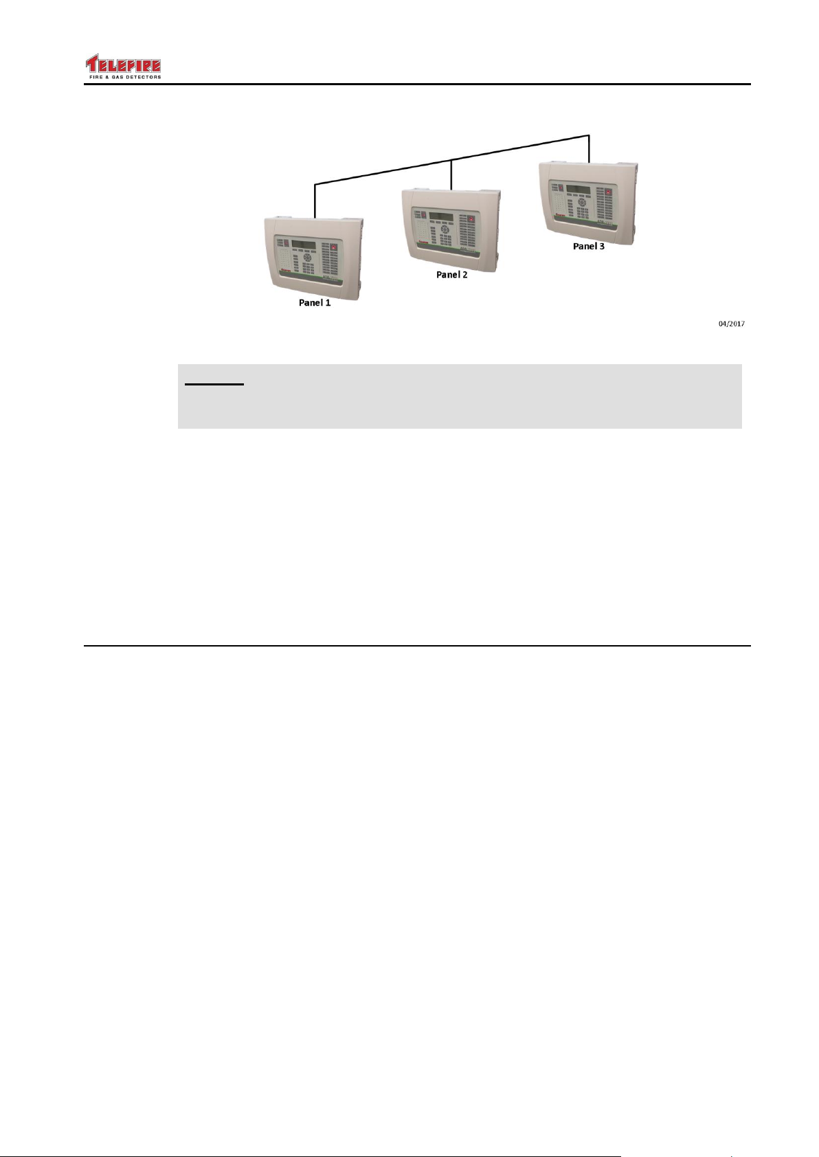
Figure 2 LON-7000 Networking communication module (ADR-7000 only)
2.6.1 Topology
An ADR-7000 LonWorks network can connect from 2 and up to as many as 32
ADR-7000 control panels in a peer-to-peer or Master-slave network. The physical
topology of the network may be bus (figure 8), ring (figure 9) or free (figure 10) topology.
Logical hierarchy may be peer-to-peer – where all messages are reported in all control
panels, master/slave – where slave messages are reported on master control panels, or
a combination of the two.
Ring topology requires LRW-102 Fiber Optic Repeaters.
Please refer to the LON-7000 technical manual for further details.
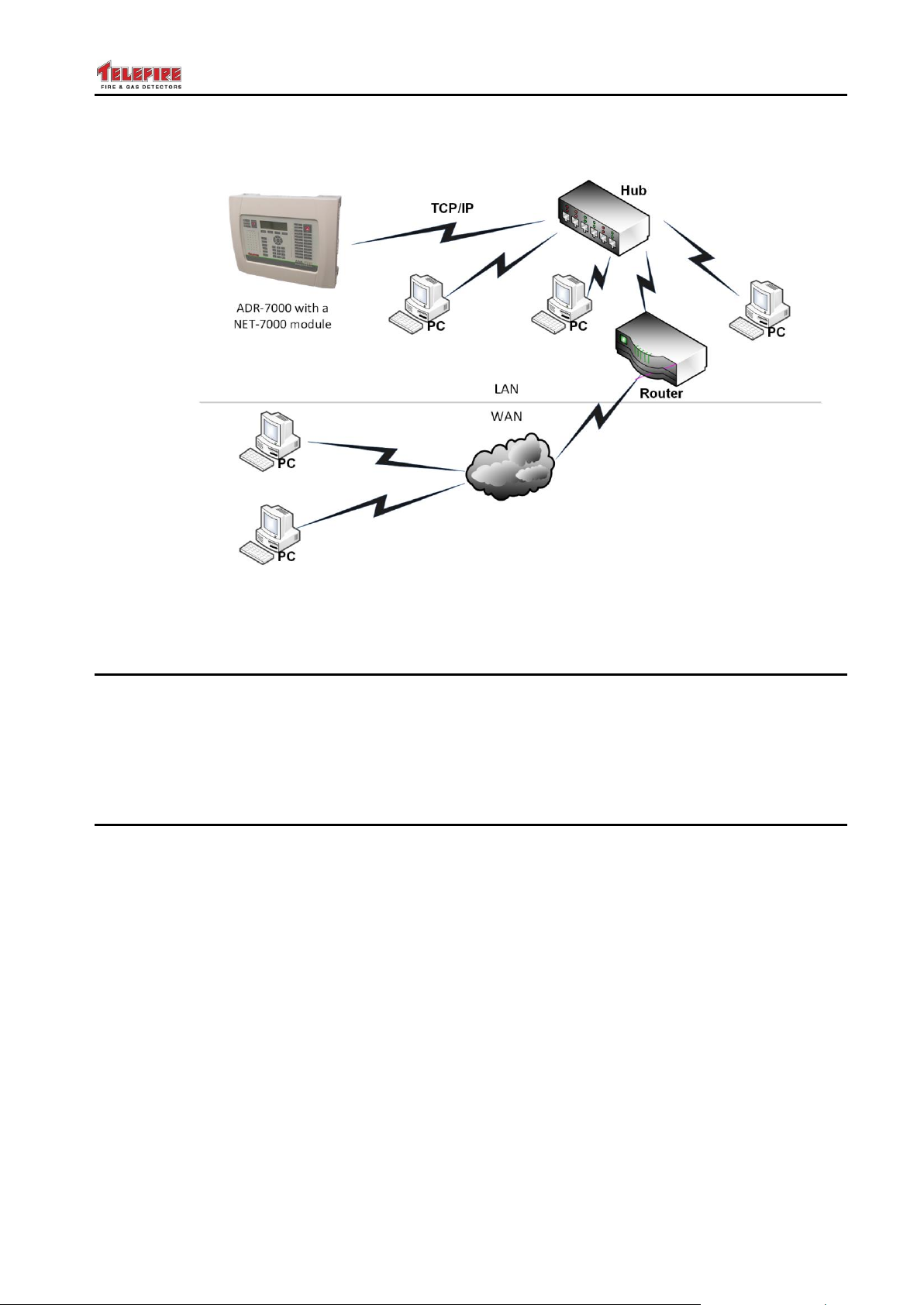
2.7 TCP/IP Module – NET-7000
The ADR-7000's internet-enabled features allow it to provide fire alarm control panel
monitoring over LAN, WAN, or Internet using a standard web browser or Telefire's
proprietary TCS-3040 software, and distribute alarm and trouble events via a built-in web
server, e-mail notification and SMS paging.
– Page 6 of 87 –
Page 13
ADR-7000 / SAVER-7000 / GUARD-7
© 2017 – Telefire Fire & Gas Detectors Ltd Revision 0.98 October 2017
Figure 3 Remote control by TCP/IP NET-7000 module
2.8 Loop Expansion Card – ADR-7001EM1 – ADR-7000 only
The loop expansion card is designed for ease of installation and maintenance.
Connectors are located in logical groups; on the left are the data and power inputs from
the main board. On the bottom are connectors for SLC loops 5-8; and Ground and
24Vdc supply to the field.
The ADR-7001EM1 card supports 1 – 4 additional SLC loops.
2.9 Remote Annunciator – RM-7000
The RM-7000 Remote Panel and Annunciator enables control and supervision of the
ADR-7000 fire alarm control panel from remote locations and key positions such as
security officer, premises manager, or maintenance office.
The RM-7000 remote panel consists of an LCD display, keyboard, internal buzzer, and
features such as alarm output, trouble output, and an interface relay that reduces the
need for additional input/output interface modules.
The remote panels are connected to the main control panel via a twisted wire pair
(RS-485). As many as 16 remote panels can be connected to the control panel using
the same cable in a Class B or Class A configuration. Each remote panel should be
configured with a unique address in the range of 1 to 16. The communication circuits
are fully supervised.
In large systems incorporating several control panels connected via a peer-to-peer
network as many as 16 remote panels can be connected to each of the control panels.
The RM-7000 operates with a 24Vdc power source that can be supplied from the main
control panel or an auxiliary power supply such as Telefire's TPS-73A or TPS-34A
Addressable Auxiliary Power Supply.
Please refer to the RM-7000 technical manual for further details.
– Page 7 of 87 –
Page 14
ADR-7000 / SAVER-7000 / GUARD-7
User
Position
User 1
Security guard
User 2
Operator – an employee of building owner or manager that has undergone
user training
User 2
Operator – an employee of building owner or manager that has undergone
user training
User 3
Programmer – someone who is qualified to install and configure the system
User 5
Programmer – someone who is qualified to install and configure the system
User 6
Master Programmer – a senior person who is qualified to install and
configure the system
Action
User 1
Users 2
and 3
Users 4 and
5
User 6
Guard
Operator
Programmer
Senior
Programmer
Scrolling events
Silence buzzer
Silence sounders
Reset
Device address
programming
Enable / disable device
Walk test
Setting time and date
Setting holiday dates
Control panel configuration
© 2017 – Telefire Fire & Gas Detectors Ltd Revision 0.98 October 2017
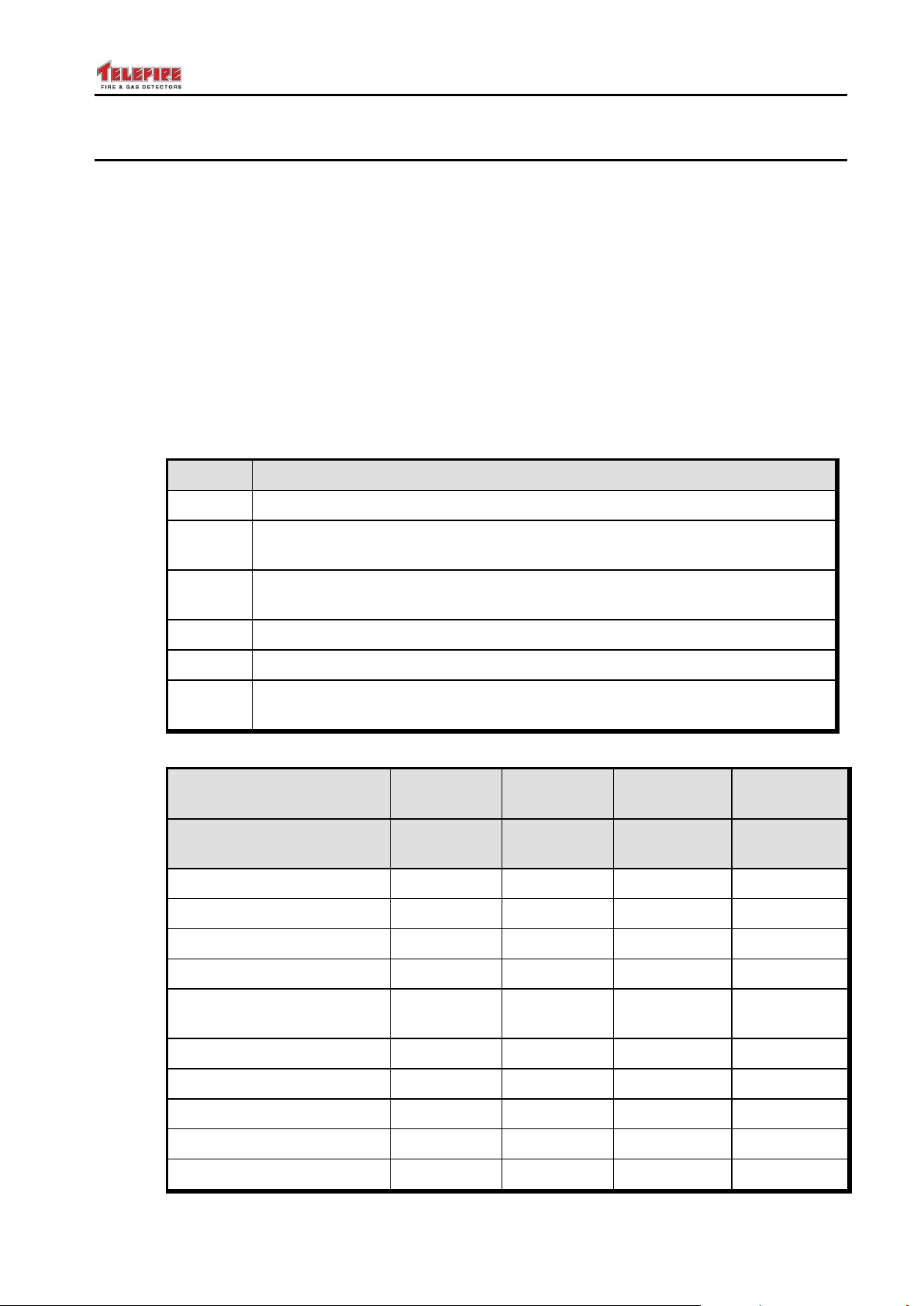
2.10 Access Levels
The control panel allows protection from unauthorized access through protection of
certain functions by various access levels.
The control panel includes an electronic locking mechanism that allows work in 4 access
levels:
Access level 1 – not limited by password
Access level 2 (operator) – protected by password. Provides all of access level 1
functions and allows access to additional functions that are performed on a regular
basis by the system operator
Access level 3 (programmer) – protected by password. Provides all of access
level 2 functions and allows access to additional functions such as configuration and
programming
Access level 4 (manufacturer) – protected by dedicated tool
There are six users, each of which has a different password:
– Page 8 of 87 –
Page 15
ADR-7000 / SAVER-7000 / GUARD-7
Action
User 1
Users 2
and 3
Users 4 and
5
User 6
Guard
Operator
Programmer
Senior
Programmer
Device programming
Keyboard unlock
Clearing extinguishing
activated sign
Can change password
for himself
for user 1
for users 2 and 3
for users 4 and 5
–
–
–
–
self only
–
self only
© 2017 – Telefire Fire & Gas Detectors Ltd Revision 0.98 October 2017
– Page 9 of 87 –
Page 16
ADR-7000 / SAVER-7000 / GUARD-7
© 2017 – Telefire Fire & Gas Detectors Ltd Revision 0.98 October 2017
3 Work States – Alarm, Fault, Supervisory, Disablement,
and Test Modes
Alarm, fault or supervisory events are shown clearly by dedicated LEDs that are labeled
Fire, Fault, and Supervisory, respectively. A detailed explanation in the LCD display
includes all relevant details for troubleshooting and proper resolution of the event.
Fire alarms, fault conditions, and supervisory conditions are defined as events. When
two events occur at the same time, the first event will be shown (alarms have a higher
priority) and the event counters in the LCD display show the number of alarms,
supervisory events, status events, faults, disablements, and addresses in test mode.
Fire alarms have a higher priority than fault events and are shown first.
To see the events in the order they occur, use the up and down arrow keys.
3.1 Normal (Quiescence) State
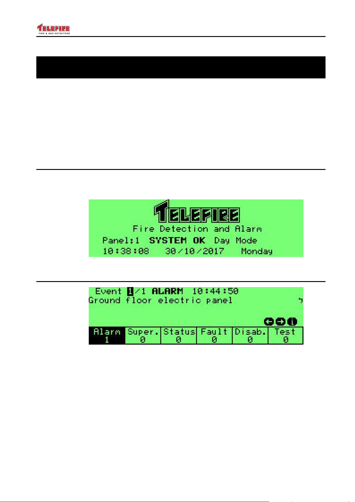
Normal state is a state where no alarm or fault event and all of the inputs and outputs
are enabled. In this state, the green power LED is turned on and the LCD displays
System OK.
Screen 1 Quiescence state
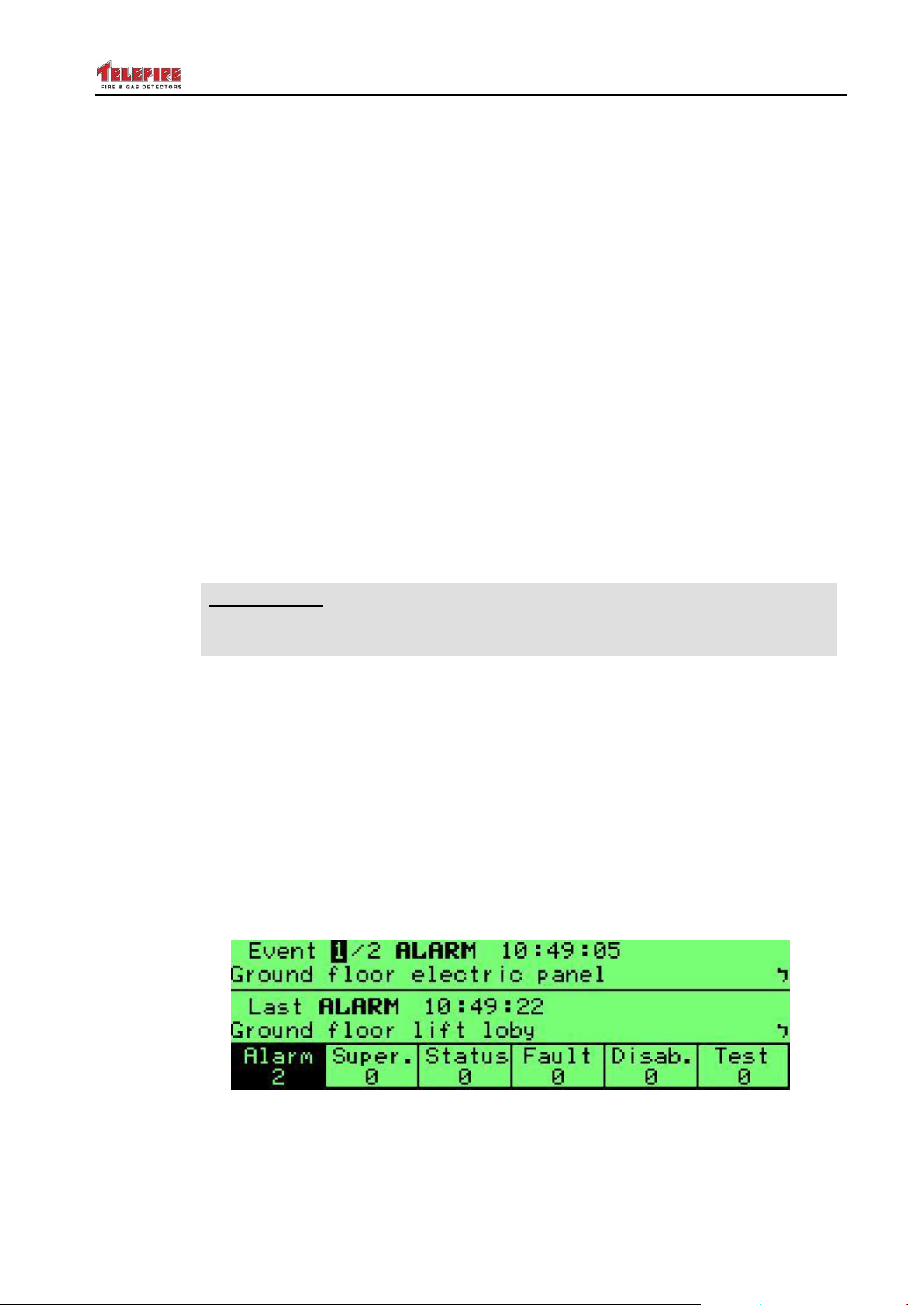
3.2 Alarm State
Screen 2 Alarm state
3.2.1 Alarm Verification
The alarm verification feature allows the control alarm to ignore momentarily false
alarms that may cause a nuisance.
When an address is programmed for alarm verification, the control panel resets the
device in alarm, waits for 0 to 59 seconds (depends on individual address programming)
and rechecks whether the same address is still in alarm. During that time, the control
panel will enter alarm state when receiving an alarm from the same or another address.
During alarm verification time, the control panel will enter alarm state immediately in
case that there is another alarm indication even if that address is programmed as alarm
verification.
– Page 10 of 87 –
Page 17
ADR-7000 / SAVER-7000 / GUARD-7
UL 864
UL Models
For UL models, pressing the Acknowledge key will stop the flashing of the
LEDs and turn them solid on.
© 2017 – Telefire Fire & Gas Detectors Ltd Revision 0.98 October 2017
In case only one alarm triggered the alarm verification clock, during and up to 120
seconds, no additional alarm is received, the clock will be reset and the control panel will
be back in normal mode.
3.2.2 Alarm Operations
During an alarm in one of the addresses, the control panel performs the following
operations
Indicating the address in alarm on the LCD display
Turning on the Fire LEDs in the LCD display and clarification area and the private
alarm zone in the zoning alarm
Displaying the alarm in the remote panel RM-7000 if connected
Logging an event in alarm history
Activating the NAC outputs in the panel
Activating dialer output
Activating internal buzzer
Activating relays that were configured as alarm relays
Activate output addresses as per matrix configuration
3.2.3 Acknowledge / Buzzer Off Operation
Silences the internal buzzer
3.2.4 Acknowledge Operation
3.2.5 Silence Operation
Pressing the Silence key performs the following actions
Stops the action of the horn output
Stops the action of the internal buzzer
Stops the alarm relay if it was programmed as silenceable
Stops outputs that were programmed as silenceable
3.2.6 Action during a Second Alarm (Two Devices in Alarm at the
Same Time)
Screen 3 Two concurrent alarms
When receiving a second alarm, (i.e., two devices are in alarm at the same time), the
control panel perform the following operations
Reactivation of all silenced output
– Page 11 of 87 –
Page 18
ADR-7000 / SAVER-7000 / GUARD-7
© 2017 – Telefire Fire & Gas Detectors Ltd Revision 0.98 October 2017
Increase the event counters on the LCD display.
Activating outputs that were programmed to activate upon an alarm from these
devices
3.2.7 Resetting an Alarm
Resetting an alarm can be done by pressing the Reset key.
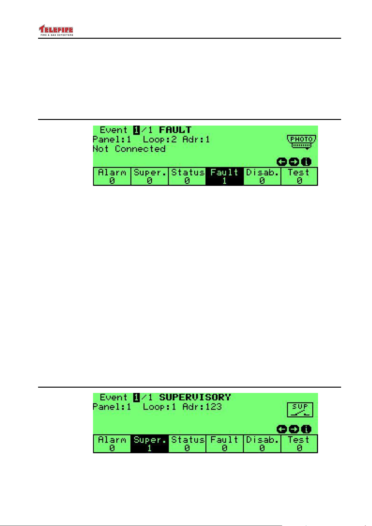
3.3 Fault State
Screen 4 Fault state
A fault in the system will be shown indicated in the system by a flashing yellow LED in
addition to the fault information in the LCD display.
3.3.1 Actions Taken in Fault State
When receiving a fault event at the control panel, the control panel will perform the
following operations
Indicating the fault in the display
Turning on the General Fault LED
Activating the internal buzzer in the control panel
Logging an event in fault history
Activating relays that were configured fault relays
3.3.2 Actions Taken Upon Event Confirmation (Pressing the "#"
Key)
Stopping LED indicator flashing, - the LEDs shall stay on until the issue is resolved
3.3.3 Actions Taken Upon Pressing "Buzzer Off" Key
Silencing the internal buzzer
Stopping the flashing of the LEDs in the general alarm area and turning them solid
on (UL version only)
3.4 Supervisory State
Screen 5 Supervisory state
The ADR-7000 has a supervisory function that conforms to UL and EN standards.
– Page 12 of 87 –
Page 19
ADR-7000 / SAVER-7000 / GUARD-7
UL 864
UL Models
For UL models of the ADR-7000, pressing the Acknowledge key stops the
flashing of the LEDs in the general alarm area, in the LCD display and
clarification area and the private LEDs in the zones and turning them solid on.
© 2017 – Telefire Fire & Gas Detectors Ltd Revision 0.98 October 2017
In certain cases, there is a need to activate an output following a fault such as indication
of low pressure in an extinguishing cylinder, closed sprinkler valve, etc.
The supervisory function answers these need and allows monitoring switch conditions
and reaction according to the state were using the fire alarm infrastructure.
Supervisory fault does not latch – at the end of the event, the system goes back to
normal state without intervention.
3.4.1 Action Taken Upon a Supervisory Event
A supervisory event will cause the following events in the control panel
Turning on the supervisory LED, the supervisory indication in the LCD display
Indicating the fault event in the RM-7000 remote panel if connected
Activating fault buzzer
Logging of the event in the fault history
Activating supervisory outputs that are in the same logical zone as the activated
fault supervisory device, if defined
Activating supervisory relays, if defined
3.4.2 Actions Taken Upon Pressing "Buzzer Off" Key
Silencing the internal buzzer
Stopping the flashing of the LEDs in the general alarm area, in the LCD display and
clarification area and the private LEDs in the zones and turning them solid on
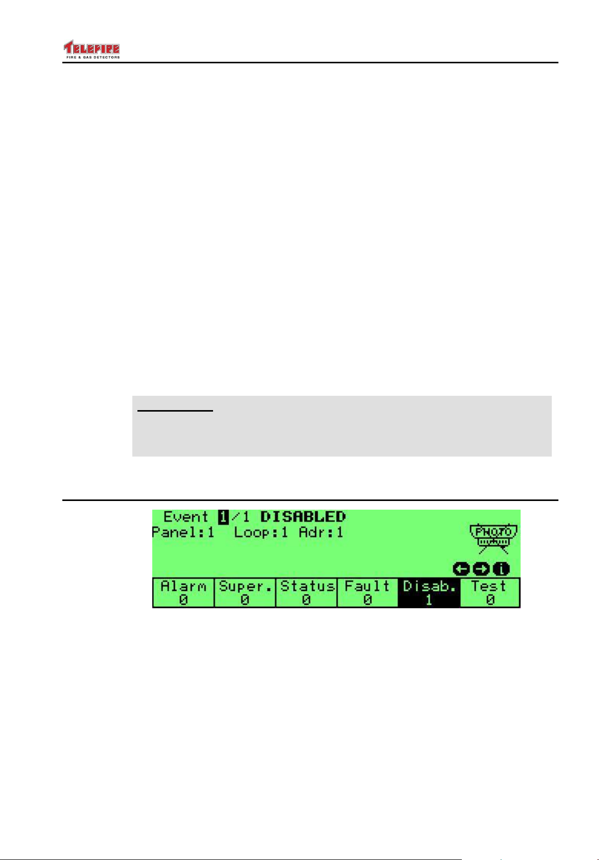
3.5 Disablement State
Screen 6 Disablement state
Sometimes there is temporarily a need to disable a particular input, output, or relay.
The control panel will ignore alarms from disabled devices or zones and will not activate
disabled outputs or relays.
When one of the devices, zones or outputs is disable, the disabled LED is turned on to
indicate this status.
– Page 13 of 87 –
Page 20
ADR-7000 / SAVER-7000 / GUARD-7
© 2017 – Telefire Fire & Gas Detectors Ltd Revision 0.98 October 2017
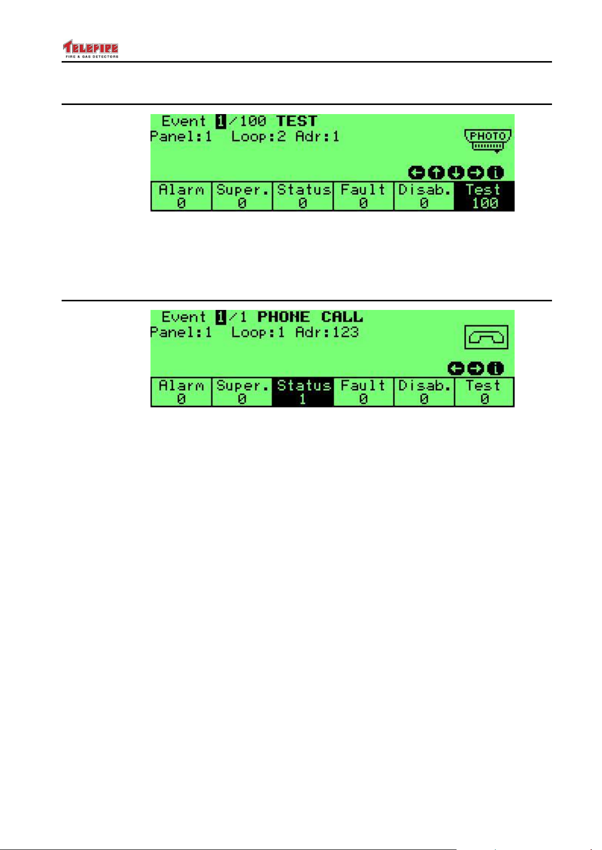
3.6 Test State
Screen 7 Test state
Test state allows testing the control panel without activating outputs. This state is
indicated by the Test LED.
See page Error! Bookmark not defined. for additional information about Field Test.
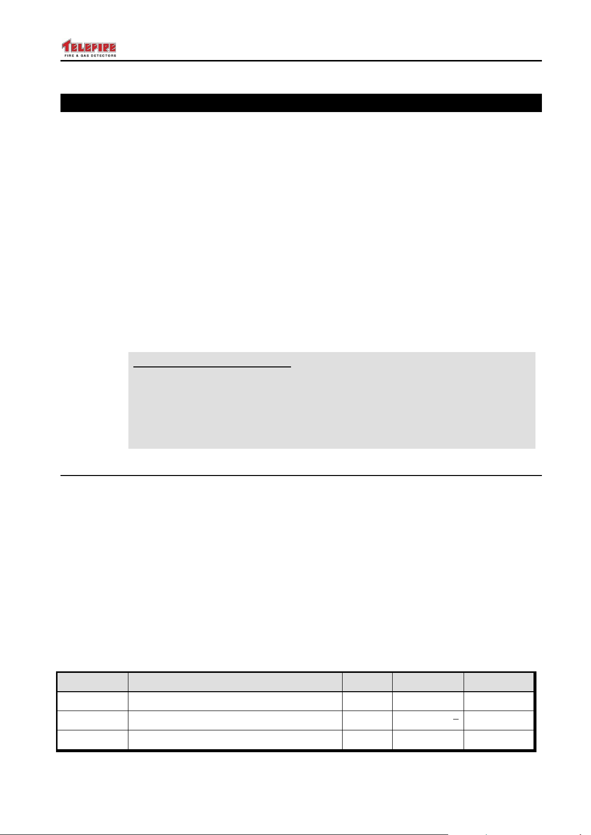
3.7 Status State
Screen 8 Status state
Status state indicates events that are not alarm, supervisory, fault, disablement, or test
states.
These events include:
Evacuation
Pre-alarm
A call on the fireman phone system
Extinguishing abort
A loudspeaker selection switch activation
Status change of a manual selector on a smoke panel
Status report from a blower or damper in a smoke system
– Page 14 of 87 –
Page 21
ADR-7000 / SAVER-7000 / GUARD-7
NFPA 72
NFPA 72 Recommendation
The NFPA (National Fire Protection Association) is the American association
for the fire safety industry. Its guideline, NFPA 72 National Fire Alarm and
Signaling Code specifies "the application, installation, location, performance,
inspection, testing, and maintenance of fire alarm systems, fire warning
equipment and emergency warning equipment, and their components" and is
considered the de-facto standard of fire alarm design and implementation.
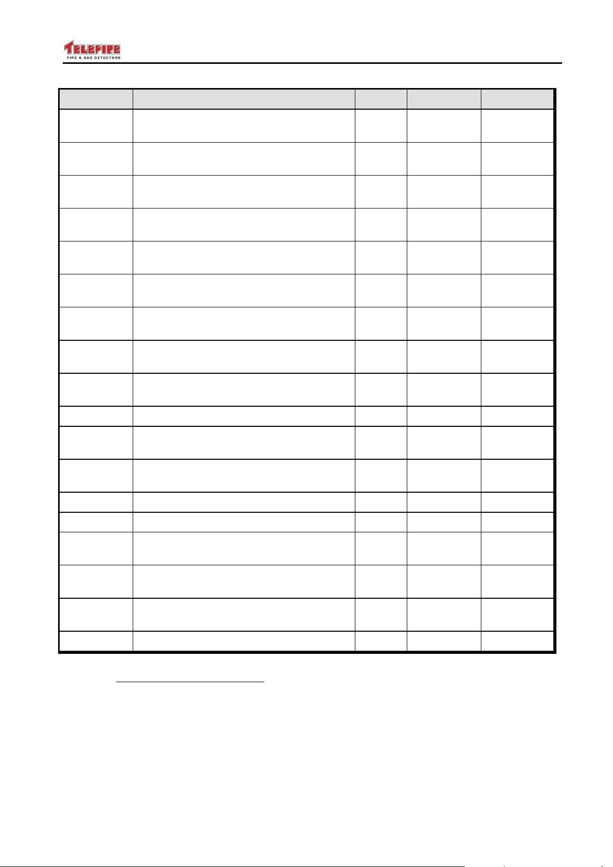
P/N
Description
QTY
Multiply by
Addresses
TFO-480A
Photo-Electric Smoke Detector
1
TFH-280A
Heat Detector
1
TPH-482A
Photo/Heat Detector
1
© 2017 – Telefire Fire & Gas Detectors Ltd Revision 0.98 October 2017
4 Installation
The planning process should take into consideration the entire system.
Start by going over the project plans and determine the quantity and location of various
detectors, call points, sounders, strobes, and other fire-safety devices as required.
Consider the NFPA 72 recommendation, local guidelines and regulations, and specific
requirements set by the fire safety consultant.
Make a list of the equipment required, taking into consideration and additional items
necessary as pre-requisite or optional accessories.
Calculate the number of addresses needed and make sure that there are sufficient
quantities of control panels and loops per control panels and allow for some spare
addresses for future requirements.
Calculate cable lengths – long cable runs may require additional control panels, loops or
auxiliary power supplies.
Calculate the current-draw requirements, both for a quiescent system and in alarm.
Calculate the size of batteries required and additional auxiliary power supplies that may
be needed.
Specify logical zones and activation matrices so that the installing engineer can
configure the control panels as necessary.
4.1 Pre-Installation Planning
Planning of quantity and location of detectors, push buttons, notification appliances and
extinguishing devices shall be done according to the local codes and regulations and in
accordance to the planning consultant's requirements.
4.1.1 Pre-Installation Planning – Capacity Planning
Calculate the number of addresses required by the system's devices.
Round up by 10% to provide sufficient available addresses to allow for future expansion
and divide by 127. Round up to the nearest whole number to calculate the required
number of SLC loops.
Divide the number of loops by 4 and round up to the nearest whole number to calculate
the minimum number of control panels required.
In some cases site-specific requirements may determine the need for more loops and/or
control panels than the minimum.
If you need more than one control panel, you will need to network multiple panels.
– Page 15 of 87 –
Page 22
ADR-7000 / SAVER-7000 / GUARD-7
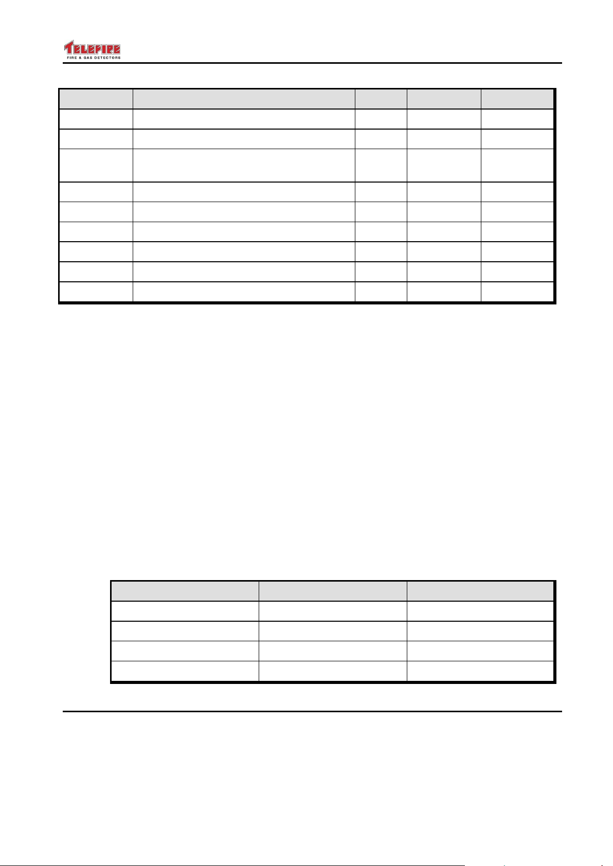
P/N
Description
QTY
Multiply by
Addresses
ADR-705
Dual Switch Interface Module configured
as a single address 1
1
ADR-705
Dual Switch Interface Module configured
as two addresses 2
2
ADR-71x
Multi Input Module configured as a single
address 2
1
ADR-71x
Multi Input Module configured as two
addresses 2
2
ADR-71x
Multi Input Module configured as four
addresses 2
4
ADR-71x
Multi Input Module configured as eight
addresses 2
8
ADR-723
High power output module configured as
a single address 3
81
ADR-723
High power output module configured as
two addresses 3
2
ADR-723
High power output module configured as
three addresses 3
3
ADR-741
Relay module
1
ADR-812A
Two-Channel Input Module configured as
a single input 4
1
ADR-812A
Two-Channel Input Module configured as
two inputs 4
2
ADR-805A
Flow Switch Interface Module
1
ADR-818A
Eight-Channel Input Module
8
ADR-823A
Three-Channel I/O Module – as a single
output 3
1
ADR-823A
Three-Channel I/O Module in
2-address configuration 3
2
ADR-823A
Three-Channel I/O Module – in
3-address configuration 3
3
ADR-828A
Eight-Channel Output Module
8
1
2
3
4
© 2017 – Telefire Fire & Gas Detectors Ltd Revision 0.98 October 2017
The ADR-705 can be configured as a single-address, or two-address module.
The ADR-71x can be configured as a single-address, or two-address module (factory default for
ADR-712) or a four address or eight address module (factory default for ADR-718).
The ADR-723 and ADR-823A can be configured as a single-address, two-address, or three-
address module as required.
The ADR-812A can be configured as a single-address or two-address module as required.
– Page 16 of 87 –
Page 23
ADR-7000 / SAVER-7000 / GUARD-7
P/N
Description
QTY
Multiply by
Addresses
ADR-833A
Extinguishing Control Unit
1
LI-3000
Line Isolation Module for Class A/B
1
TIP-224A
Addressable Indoor Alarm Notification
Sounder
1
TPS-73A
Auxiliary Power Supply
1
TPS-34A
Auxiliary Power Supply
1
TFP-3000
Fireman Phone Control Unit
25
TFP-1CP
Single Handset Fireman Phone Unit
1
TFP-806
Fireman Phone Socket
1
TFP-828A
8-Zone Display Module for the TFP-80C
8
SLC
Outputs
Electric Resistance
Minimal
Very High
Capacitance
High
No Influence
Inductance
High
Minimal
Mechanical Strength
High
High
© 2017 – Telefire Fire & Gas Detectors Ltd Revision 0.98 October 2017
Table 3 Address Requirements
4.1.2 Power Requirement Calculation
Calculate the current consumption of the control panel and attached devices in
quiescence state and during alarm to determine battery capacity and check if any
auxiliary power supplies are required. Please refer to section Error! Reference source
not found., page Error! Bookmark not defined. for additional details.
An external power supply (TPS-74A or TPS-34A) is required if any of the following
conditions are met:
Quiescence (normal) mode current consumption is more than 0.5A
Alarm current is more than 4.0A
Required battery capacity is more than 12AH
Please see section 0 ("When are Auxiliary Power Supplies Needed?") on page 84 for
a detailed explanation about the requirements of auxiliary power supplies.
Please refer to the TPS-34A technical manual for further details.
4.1.3 Pre-Installation Planning – Effect of Cable Characteristics on
System Performance
The following table summarizes wiring characteristics' influence on system performance.
4.2 Cable Planning
4.2.1 Cable Planning – SLC (Loop) Cable
The ADR-7000 allows wiring of the SLC loop in a closed loop (NFPA Style 6 Class A) as
well as branching T-shaped (NFPA Style 4 Class B) wiring configuration.
– Page 17 of 87 –
Page 24
ADR-7000 / SAVER-7000 / GUARD-7
i
Note
Class A is defined per line card in the ADR-7000. In a control panel that has
more than one line card, it is possible to have some of the line cards working
in Class A, and the others working in Class B.
Wire Type
Cross-Section
Maximum SLC Branch Length for given cross-
section
18 AWG
0.8 mm2
950 m
3,130 ft.
16 AWG
1.3 mm2
1,520 m
4,970 ft.
14 AWG
2.1 mm2
2,420 m
7,940 ft.
12 AWG
3.3 mm2
3,830 m
12,580 ft.
© 2017 – Telefire Fire & Gas Detectors Ltd Revision 0.98 October 2017
Class A configuration requires a minimum of one LI-3000 or LI-3000E module per loop.
The outgoing wiring in Class B or Class A cabling should be connected to the SLC Out
terminator on the left (marked as ), and the Class A return wire to the terminator on the
right (marked as ).
A group of devices should be connected in a section between two isolators. Each
section is protected from short-circuit that may occur in other loop sections. Configure
the loop card as Class A.
Configuring a loop as Class A does not reduce loop capacity, other than the addresses
taken by the isolation modules. Each SLC loop is capable of addressing 127 devices,
including the addresses occupied by the LI-3000 modules.
Use up to 20 LI-3000 line isolators per SLC loop.
4.2.2 Cable Planning – SLC (Loop) Cable Selection
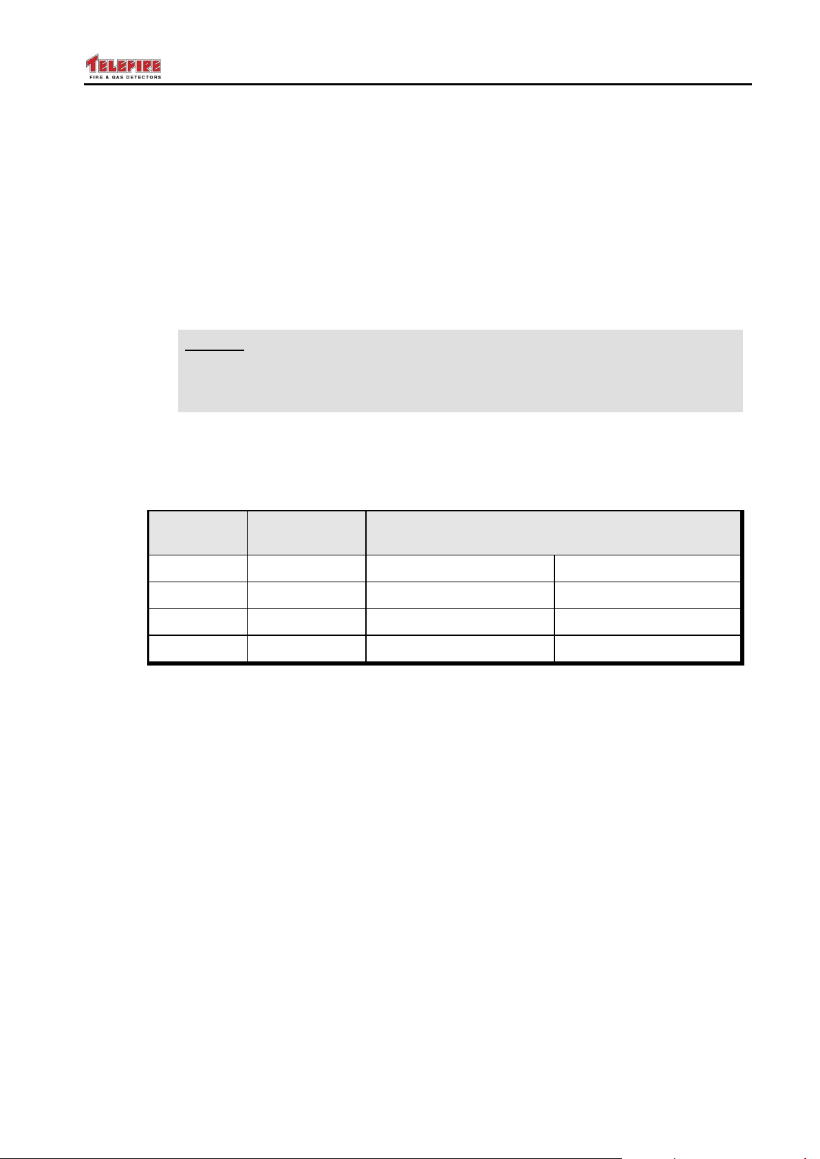
Use a twisted pair wire 18 to 12 AWG and follow the guidelines in the table below for
wire selection.
Table 4 Maximum SLC Loop Length
4.2.3 Cable Planning – 24Vdc Supply to Devices
The length of activation lines and 24Vdc Out cabling depends on the required current
and cable size. Cable resistance running between the 24Vdc source to the I/O module
and from the I/O module to the device should be calculated. Ensure that no device
receives a voltage below its specified minimum operating value and that the total voltage
drop will not exceed 2 volts, (i.e., the last device on the line receives at least 22Vdc
when activated).
4.2.4 Cable Planning – 24Vdc Supply to ADR-823A Modules
It is recommended to use ADR-723 with the ADR-7000. If there is a need to use
ADR-823A modules with the ADR-7000, use an LDO-7000 voltage adaptor connected to
the 24Vdc output on the ADR-7000. Connect the ADR-7000's 24Vdc output to the In TB
of the LDO-7000, and the Out TB of the LDO-7000 to the field.
4.2.5 Cable Planning – NAC Outputs
The length of NAC activation lines cabling depends on the required current and cable
size. Cable resistance running between the NAC outputs to the device should be
calculated. Ensure that no device receives a voltage below its specified minimum
operating value and that the total voltage drop will not exceed 2 volts, (i.e., the last
device on the line receives at least 22Vdc when activated).
– Page 18 of 87 –
Page 25
ADR-7000 / SAVER-7000 / GUARD-7
Wire Type
Belden
85102
Belden
8471
Level IV
22 AWG
JY (St) Y
2*2*0.8
Bus topology:
Maximum bus length (meters)
2,700
2,700
1,400
900
Free topology
Maximum node-to-node distance
(meters)
500
400
400
320
Free topology
Maximum wire length (meters)
500
500
500
500
Resistance (Ω/km)
15
28
55
73
Capacitance (nF/km)
56
72
56 (at 1 MHz)
98
i
Note
Redundant ring topology can be done only via fiber-optic cabling.
© 2017 – Telefire Fire & Gas Detectors Ltd Revision 0.98 October 2017
4.2.6 Cable Planning – Remote Annunciators
RM-7000 remote annunciators are connected to the control panel via a four-wire
connection (two-wire, single-core RS-485 data cable, and two-wire, single-core 24Vdc
supply from either the control panel or an auxiliary power supply).
Cabling will be done as per the recommendation of RS-485 and local fire regulations –
the more stringent of the two. Long distance cables or cables between buildings or
rooftops shall be shielded.
The cabling from the control panel to the remote panels is in linear (bus) topology.
Maximum total cable length (control panel to the last RM-7000) is 1,220 m.
The RS-485 standard does not specify cable characteristics. However, it is based on
the RS-422 standard, which recommends 24 AWG twisted pair cable with a shunt
capacitance of 16 pF per foot and 100 Ohm characteristic impedance. These
recommendations should be used for RS-485 systems as well.
Many available cables are designed specifically to meet the recommendations of
RS-422 and RS-485 specification. Another choice is the same cable commonly used in
the Shielded Twisted Pair Ethernet cabling. This cable, commonly referred to as STP
Category 5 cable, is defined by the EIA / TIA / ANSI 568 specification. The extremely
high volume of Category 5 cable used makes it widely available and very inexpensive,
often less than half the price of specialty RS-422 / 485 cabling. The cable has a typical
capacitance of 14.5pF/ft and characteristic impedance of 100 Ohms.
Maximum total cable length is 4,000’ (1,220m).
4.2.7 Cable Planning – LON-7000 Galvanic Networks
It is possible to extend the ADR-7000's capacity by networking two or more (as many
as 32) control panels in a Master/Slave or Peer-to-Peer network.
In order to maximize the distance between ADR-7000 control panels interconnected in a
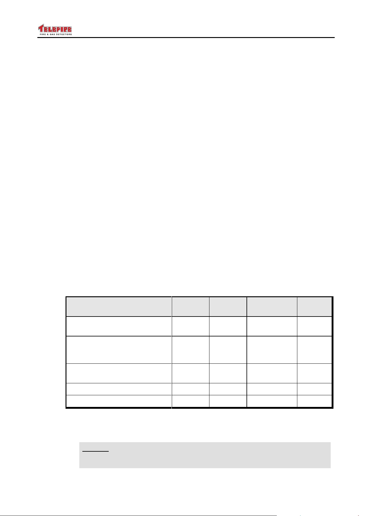
LonWorks network use a twisted pair cable of the types described in the following table.
The wires should enter the cabinet through the "Power Limited" wire entrances on
either the top right or bottom right of the ADR-7000 cabinet.
Table 1 Maximum LON Cabling Length
Cabling topology can be bus, free, redundant ring, or a mixture of any two or all three
topologies.
– Page 19 of 87 –
Page 26

ADR-7000 / SAVER-7000 / GUARD-7
i
Note
Do not activate extinguishing devices by a Global Matrix (activated by logical
zones of devices physically connected to other control panels on the
network).
© 2017 – Telefire Fire & Gas Detectors Ltd Revision 0.98 October 2017
4.2.8 Cable Planning – LON-7000 Fiber Optic Networks
Cable length limitations, requirements for galvanic isolation, or environmental
electromagnetic interference may require network connection via a fiber-optic
connection.
The LRW-102 provides an easy solution for implementation of extending LonWorks
networks. The LRW-102 is completely transparent as far as the LonWorks protocol is
concerned, and does not require any additional addresses. The LRW-102 allows
implementation of fiber-optic networks in point-to-point, bus, or Class A redundant ring
topologies. The LRW-102 has a built-in support for redundant ring topology.
4.2.9 Cabling Planning – ADR-7000 to TFP-3000 Fireman's Phone
Use two-wire cables (twisted-pair is recommended) 18 to 12 AWG (cross section of 0.8
to 3.3 mm2).
Two pairs from the ADR-7000 to the TFP-3000 – one pair for 24Vdc supply and one pair
for SLC communication.
4.2.10 Pre-Installation Planning – Current Consumption and Battery
Capacity
Additional TPS-34A power supplies are required if one or more of the following
conditions is true:
The quiescence 24V current draw exceeds the control panel's power supply
limitations (0.5A for ADR-4004TSW)
The 24V current draw in alarm exceeds the control panel's power supply limitations
(4.0A for ADR-4004TSW)
There is a need for batteries in capacity that exceeds the control panel's power
supply limitations (12AH for ADR-4004TSW)
The voltage drop on the 24V lines exceeds allowed limitation (no more than 2V at
the furthest device, while still leaving sufficient voltage for the device to operate).
Calculate the power requirement for each ADR-7000 control panels to see whether
additional power supplies are needed. See "When are auxiliary power supplies
needed?" on page 86 for current draw calculations.
4.2.11 Pre-Installation Planning – Activation Matrices
Plan the activation logic as specified by the consultant and local standards and
regulations.
4.2.12 Pre-Installation – Releasing Planning
The size and quantity of extinguishing devices shall be calculated by authorized
personnel in accordance to the consultant's requirements and local regulations.
– Page 20 of 87 –
Page 27

ADR-7000 / SAVER-7000 / GUARD-7
© 2017 – Telefire Fire & Gas Detectors Ltd Revision 0.98 October 2017
4.3 Wiring
Cable selection and cabling work shall be done according the rules and regulations
specified by the authority having jurisdiction and planning consultant.
System connections shall be done when power sources are disconnected.
Changing/installing electric activation modules shall be done after the system is in
quiescence state (push buttons and detectors in normal state).
4.4 Installation of Detectors, I/O Modules, and Other Modules
Install detectors, I/O modules, and other equipment as necessary. Program each
device’s address prior to connecting it to the system.
4.4.1 Mounting the Control Panel's Cabinet
The control panel’s cabinet should be installed in a clean, dry, vibration-free indoor
location. Avoid exposure to severe conditions such as high humidity, dust and air
pollution.
The ADR-7000 should be mounted on a solid wall in order to allow easy access for
installation, daily operations and maintenance.
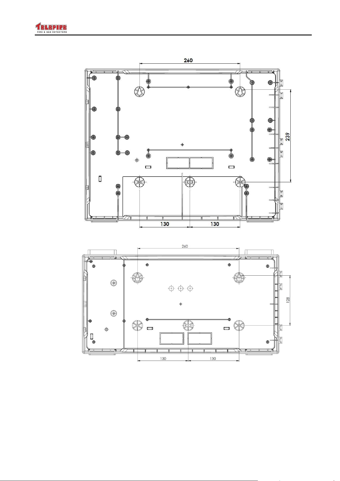
The cabinet should be mounted by using the two sliding slots on the upper back part of it
and a screw hole on the lower part.
Mains input (AC power) should enter the cabinet through either the top left or bottom left
knockout holes. Low voltage connections (SLC loops; 24Vdc; RS-232 to a NET-7000,
printer, or PC; LonWorks connection to other control panels; RS-485 to RM-7000; and
NAC outputs) should be connected through the top right, bottom right, or back knockout
holes – according to the installer’s convenience.
– Page 21 of 87 –
Page 28
ADR-7000 / SAVER-7000 / GUARD-7
© 2017 – Telefire Fire & Gas Detectors Ltd Revision 0.98 October 2017
Figure 4 Mounting holes in the Chassis
– Page 22 of 87 –
Page 29
ADR-7000 / SAVER-7000 / GUARD-7
© 2017 – Telefire Fire & Gas Detectors Ltd Revision 0.98 October 2017
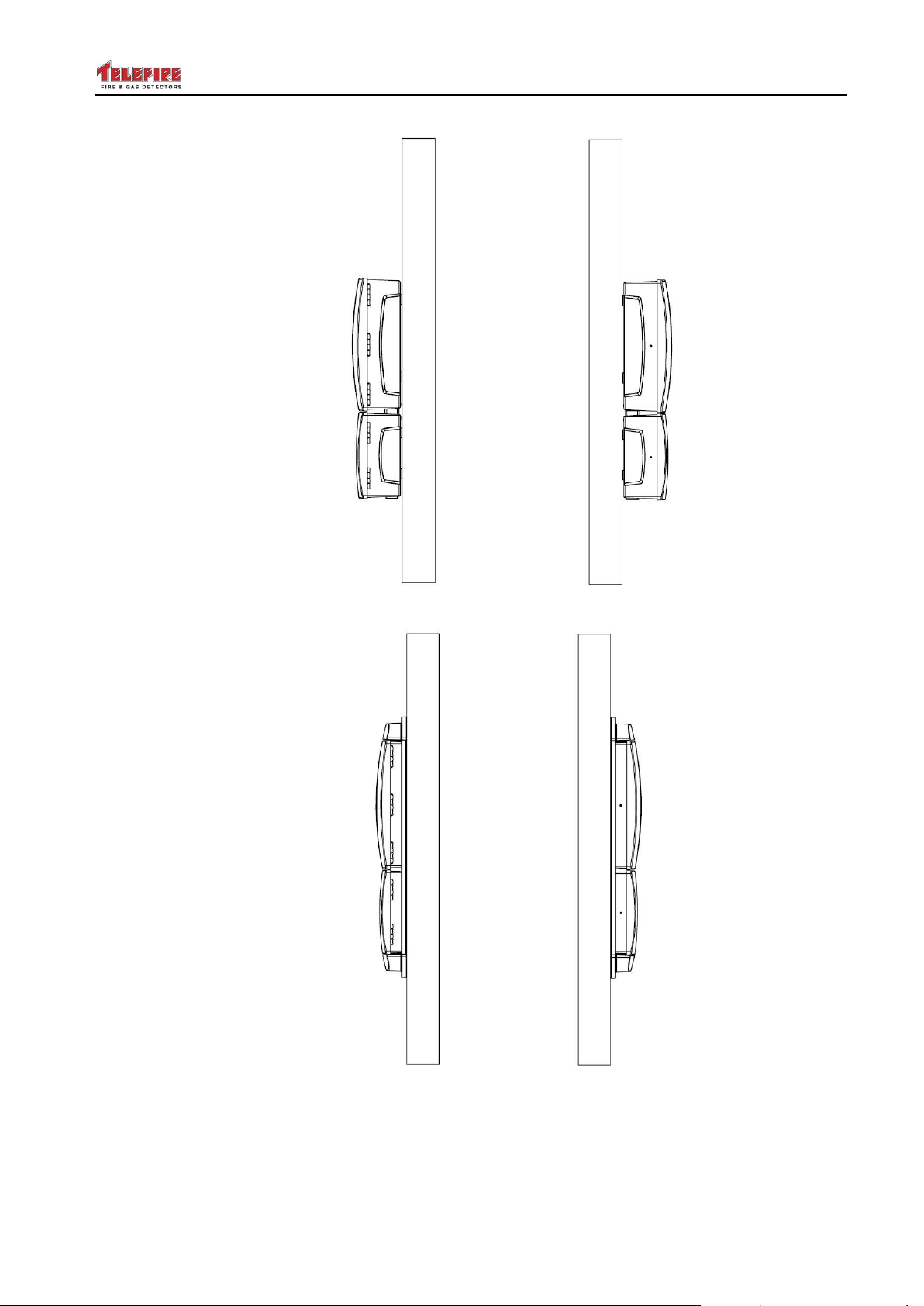
Figure 5 Mounting
Figure 6 Flush Mounting
The wiring opening on the top right of the cabinet should be covered with a metal sheet.
If no wires enter the cabinet through this opening close it with the plain cover, otherwise
use the cover with two round holes and a plastic sealing grommet.
– Page 23 of 87 –
Page 30
ADR-7000 / SAVER-7000 / GUARD-7
i
Note
All power-limited circuit wiring must be at least 0.25" (6.35mm) away from
any non power-limited circuit wiring. Use different entries of the cabinet or
conduits. See Figure 27 on page 11).
© 2017 – Telefire Fire & Gas Detectors Ltd Revision 0.98 October 2017
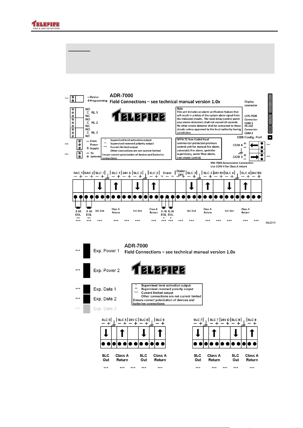
4.4.2 Field Connection Diagram
Figure 7 Connection Diagram – Main Board (ADR-7000 and SAVER-7000)
Figure 8 Connection Diagram – Loop Expansion Board (ADR-7000 only)
– Page 24 of 87 –
Page 31
ADR-7000 / SAVER-7000 / GUARD-7
© 2017 – Telefire Fire & Gas Detectors Ltd Revision 0.98 October 2017
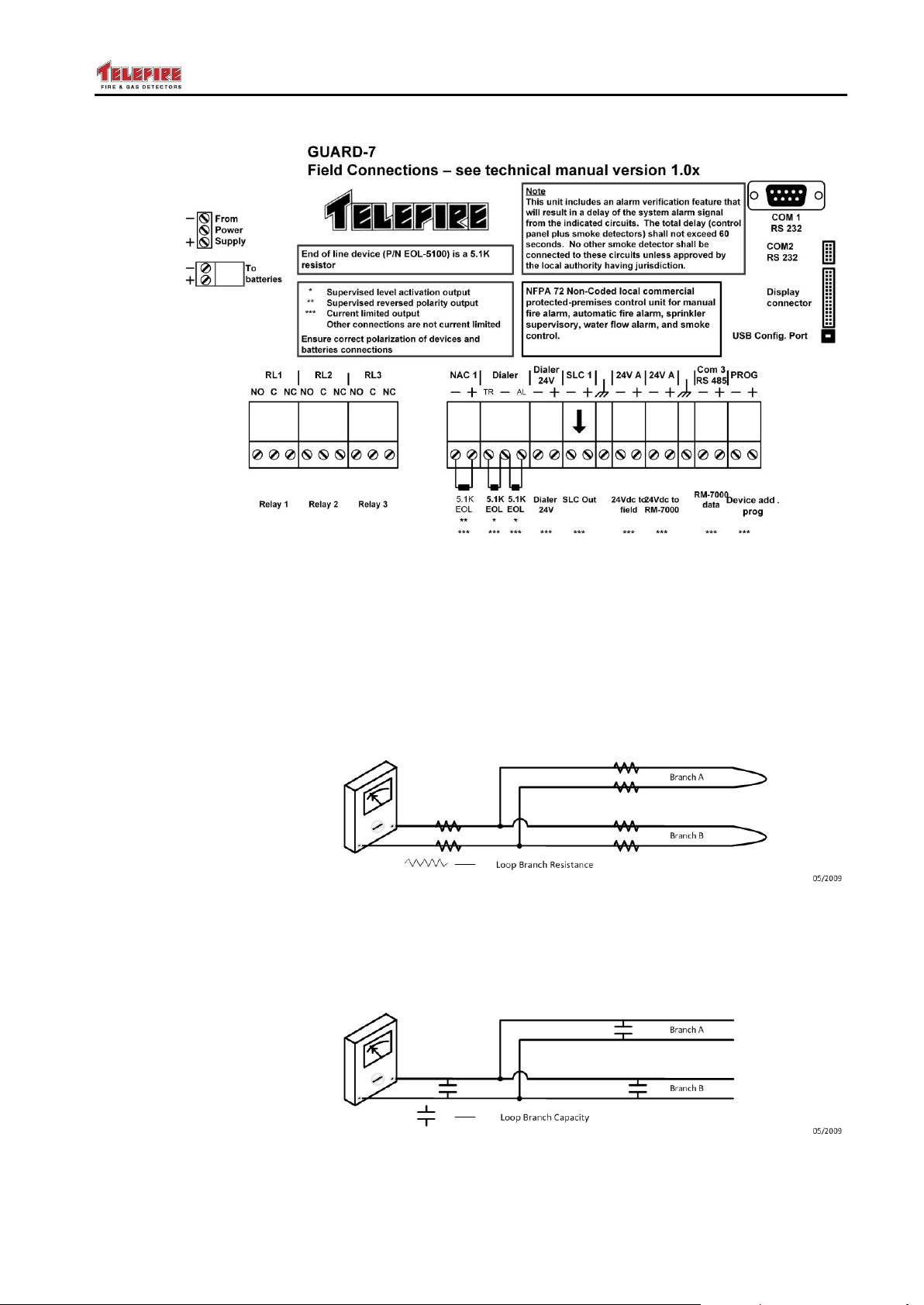
Figure 9 Connection diagram – GUARD-7
4.4.3 Testing the SLC Loops
Resistance measurements:
Short the end of one branch and measure the resistance from the connections of the
loop to the control panel. Make sure that the resistance does not exceed 40Ω. Repeat
for each input or SLC. For systems that have an NFPA SLC style 4 T branching repeat
the test for each branch separately. Make sure that the sum of all branches in a loop
does not exceed 40Ω.
Figure 10 Testing Loop Resistance
Capacitance measurements:
Connect all branches and ensure that the total capacitance of a loop does not exceed
1.0µF
Figure 11 Testing Loop Capacitance
– Page 25 of 87 –
Page 32
ADR-7000 / SAVER-7000 / GUARD-7
!
Warning
Measure the wiring to ensure there are no shorts or ground faults prior
to connecting field cabling to the control panel.
Connection or adding loops, i/o modules, detectors, etc., will be
performed when all power supply sources (mains and batteries) are
disconnected.
© 2017 – Telefire Fire & Gas Detectors Ltd Revision 0.98 October 2017
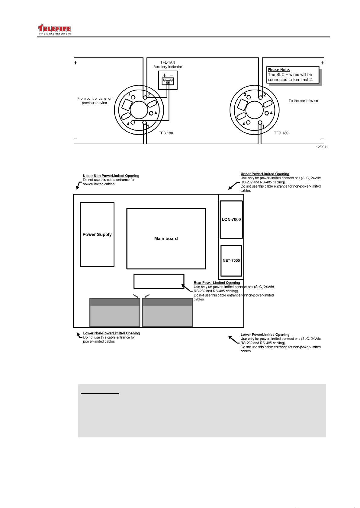
Figure 12 Example connection – detectors
Figure 13 ADR-7000 cable routing
4.4.4 Connecting Low-Voltage Devices
Connect the loops, 24Vdc supply to field, control panel outputs (dialer, NACs, relays),
remote annunciators, and other panels, as applicable. See Figure 7 and Figure 8 for
– Page 26 of 87 –
field connection diagram.
Page 33

ADR-7000 / SAVER-7000 / GUARD-7
!
Warning
Do not connect extinguishing devices at this time. Use a dummy load
to test.
i
Note
Ensure that detector initialization is performed when all detectors are in a
smoke-free condition.
© 2017 – Telefire Fire & Gas Detectors Ltd Revision 0.98 October 2017
4.4.5 Connecting AC Power
Connect the control panel’s AC input line to a dedicated circuit breaker that is not shared
by other appliances or equipment. It is recommended that the circuit breaker shall be
clearly labeled "FIRE ALARM".
The power cable should enter the control panel through either the top left or bottom left
knockout opening and separated from the field wiring Use a plastic bushing that fits the
opening. Connect the Live and Neutral wires to the proper terminal. Connect the
Ground wire directly the panel's chassis using the marked ground screw.
4.4.6 Site-Specific Configuration (Programming)
Control panel programming shall include the control panel's configuration; device
properties and description; and activation matrices.
It can be done in one of two ways:
Pre-planning by using the TCS-7030 software and creating a configuration plan and
downloading it to the control panel. Compare planned and installed configuration
after download.
Perform auto-program by using Error! Reference source not found. (see section
Error! Reference source not found. on page Error! Bookmark not defined.).
The control panel shall scan every address on every loop. Every device that is
physically connected to the control panel shall automatically be enabled, and
configured as the default options for that particular device type. It is possible to
modify parameters and options from the control panel or tcs730.
See chapter Error! Reference source not found. on page Error! Bookmark not
defined. for a detailed description.
4.4.7 Ensure All Devices are identified
Compare the number of devices scanned by the control panel to planned devices to
check for misconfigured or uninstalled devices.
4.4.8 Initialize Detectors
Each smoke detector adjusts itself gradually according to changes of environmental
conditions, by measuring and calculating the new reference value needed for signal
processing.
This process normally requires a period of several hours. When the system is turned on
for the first time, or after installing or changing a detector, it is recommended to perform
the initialization process.
If this action is not performed, the adjustment will be completed automatically within a
few days of operation.
See section Error! Reference source not found. on page Error! Bookmark not
defined. for an explanation on performing detector initialization.
– Page 27 of 87 –
Page 34
ADR-7000 / SAVER-7000 / GUARD-7
!
Warning
Testing detectors with an aerosol spray may cause increased
contamination in the labyrinth chamber due to accumulation of oil
residue and dust. This accumulation may shorten the detectors lifespan and require it to be sent to the factory for cleaning.
© 2017 – Telefire Fire & Gas Detectors Ltd Revision 0.98 October 2017
4.5 Post-Installation
4.5.1 Control Panel Activation
During the first power on you will be asked to key in an activation code. This 8 digit is
unique to each control panel.
You can get the code with a mobile phone application Telefire Reg7 that is available in
Google Play app store for Android phones, or with a phone call to 03 970 0444.
Screen 9 registration screen
4.5.2 Field Test
Perform a Walk Test and activate each initiating device to verify that it is working
properly. See section Error! Reference source not found. on page Error! Bookmark
not defined. for details on performing a Walk Test.
4.5.3 Verification of Conditional Activation
Ensure that extinguishing devices are not armed. Connect a dummy load to
extinguishing device outputs and test activations of all output devices.
When you are satisfied that all activation programming is according to design
specifications and that there are no intermittent errors is the system you can arm the
extinguishing devices.
4.5.4 Arm Extinguishing Systems
Ensure all input devices are in normal state and no devices are in alarm and arm the
extinguishing mechanisms.
4.5.5 Change passwords
It is recommended to change the default passwords after completing the installation and
system testing to prevent unauthorized access. See section Error! Reference source
not found. on page Error! Bookmark not defined. for explanation on changing
passwords.
– Page 28 of 87 –
Page 35

ADR-7000 / SAVER-7000 / GUARD-7
!
Warning
Forgotten passwords require factory reset: if you lose or forget the
password, the panel must be sent back to the factory to be reset. There
is no field option for gaining access to the panel without a valid
password.
Once you have changed the password, it is important that you write it
down somewhere and store it in a safe place.
© 2017 – Telefire Fire & Gas Detectors Ltd Revision 0.98 October 2017
4.5.6 System Documentation
Attach the followings to the system's front panel, or place it in a prominent position
nearby:
A list of areas/zones as installed in the protected premises
Actions to be taken upon events of alarm or fault by the operators
The name of the installing company and the service telephone number should be
clearly marked on the panel itself or on an attached diagram
– Page 29 of 87 –
Page 36
ADR-7000 / SAVER-7000 / GUARD-7
EN 12094
EN 12094 Requirement
See section 14.6 on page 87 for ADR-7000 EN 12094-1 compliance.
UL 864
UL Requirement
UL 864 paragraph 36.1.7 states that "An automatic delay provided prior to
release operation by a system shall be a maximum of 60 seconds, timed from
a release initiation condition, either from the actuation of a single detector, or
from the actuation of the second circuit or detector for cross-zone and singlezone multiple-detector, or a combination of the two operations"
IS 1220
IS 1220 Requirement
Do not combine alarm verification utilizing delay and cross zone verification.
Total delay for activation of extinguishing (detector verification delay and
extinguishing activation delay) shall not exceed 60 seconds.
i
Note
The control panel supports EN 12094 "Hold" function and UL 864 "Abort"
function as per the appropriate standard requirement.
© 2017 – Telefire Fire & Gas Detectors Ltd Revision 0.98 October 2017
5 Automatic Extinguishing
After receiving an alarm from the zone or across zones that belong to the automatic
extinguishing outputs, the extinguishing process starts. If an extinguishing delay was
defined, the delay system starts to operate. At the end of the delay the extinguishing
output (NAC A in ADR-823A or any NAC in the ADR-723) is activated. The default
duration of the extinguishing pulse is 15 seconds.
The extinguishing pulse can be configured from 5 to 55 seconds in 5 second steps; in
steps of 1 minutes between one minute to 239 minutes, or constant (that is, it will stay on
until the control panel is reset).
5.1 Extinguishing Output and Extinguishing Controller
An output device that is configured as an extinguishing controller or an extinguishing
output differs from an output that is configured as an "And" matrix in several ways:
An extinguishing can be configured to provide an extinguishing pulse with a
configurable duration or until the control panel is reset
An extinguishing output has a higher priority when allocating currents
An extinguishing output can be configured to be triggered by a single input
An extinguishing matrix may include inputs (Pressostat, Emergency Abort,
Emergency Hold, Gas flow switch, or Manual Only switch)
Activation of an extinguishing output will result in a notification that extinguishing
was activated in the control panel. Pressing the Reset key will not cancel this
indication in order to ensure extinguishing agent replacement or refill
5.2 Manual Activation
See chapter 8 on page 41 for a detailed explanation about device programming.
5.3 Extinguishing Delay
– Page 30 of 87 –
Page 37
ADR-7000 / SAVER-7000 / GUARD-7
UL 864
UL Requirement
UL 864 requires that extinguishing disconnect shall be a physical switch and
not accomplished by software.
Extinguishing disconnect shall be shown as a supervisory event.
An extinguishing disconnect switch shall be installed near the extinguishing
device.
© 2017 – Telefire Fire & Gas Detectors Ltd Revision 0.98 October 2017
The Control panel supports fire extinguishing Hold (EN 12094) / Abort (UL 864) buttons.
A device defined as a fire extinguishing Hold (EN 12094) / Abort (UL 864) button delays
fire extinguishing activation as long as the button is pressed.
Releasing the button will resume the countdown that had been suspended while the
button was pressed, if the countdown had not ended. If the countdown had ended, fire
extinguishing will activate within 5 seconds after the button was released.
Pressing the Extinguishing activation call point overrides this function.
See chapter 8 on page 41 for a detailed explanation about device programming.
5.4 Extinguishing Disconnect
Activating the cut off extinguishing switch (a key) will cut off the fire extinguishing output
circuit. The fire extinguishing output circuit will be deactivated until the switch is returned
to normal mode – this is intended for use during service and/or maintenance work.
The extinguishing disconnect is displayed on the control panel as a supervisory event.
The extinguishing disconnect switch will be installed near the fire extinguishing device.
Figure 14 Extinguishing disconnect switch
See chapter 8 on page 41 for a detailed explanation about device programming.
5.5 Extinguishing Notification and Action to Perform after Release
After extinguishing activation, the display will indicate that an extinguishing device was
activated.
Pressing the Reset key will not cancel this indication in order to ensure cylinder
replacement or refill.
– Page 31 of 87 –
Page 38
ADR-7000 / SAVER-7000 / GUARD-7
i
Note
Re-fill or replace the extinguishing device, enter programming mode and
return the control panel to normal operation select 5 Utilities on the main
menu and then 2 Clear Activated Extinguisher in order to return the control
panel to normal operation.
This action shall be performed by authorized personnel.
UL 864
UL Requirement
UL 864 paragraph 36.1.7 states that "An automatic delay provided prior to
release operation by a system shall be a maximum of 60 seconds, timed from
a release initiation condition, either from the actuation of a single detector, or
from the actuation of the second circuit or detector for cross-zone and singlezone multiple-detector, or a combination of the two operations"
!
Warning
Connect only extinguishing devices that are authorized by Telefire and
the authority having jurisdiction.
© 2017 – Telefire Fire & Gas Detectors Ltd Revision 0.98 October 2017
Ensure that the control panel is back to normal operation.
– Page 32 of 87 –
Page 39
ADR-7000 / SAVER-7000 / GUARD-7
© 2017 – Telefire Fire & Gas Detectors Ltd Revision 0.98 October 2017
6 Display and Keyboard
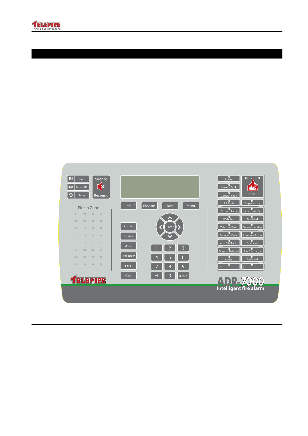
This chapter describes the panel's display, which includes an LCD, LED system
indicators, and keyboard that are used by operators for normal operations and by
programmers during installation and maintenance. A password is required to respond
from the panel keys.
The ADR-7000's user interface panel is divided into three parts:
The leftmost part has four keys to silence and resound alarms, perform practice drills,
silence the buzzer, and reset the control panel. Below these keys in a space for optional
zone display LEDs.
The central part had a 260 by 64 pixel graphical LCD, and various keys for the operator
and allows the system Programmer/Supervisor to execute operations such as changing
detector’s sensitivity, turning devices Enable / Disable, setting operating modes, etc.,
Programmer / Supervisor actions can only be performed after keying in a second-level
password.
On the right are status and informational indicating LEDs.
Figure 15 ADR-7000 Display and Keyboard
6.1 LCD Display
A 260 by 64 pixel graphical LCD is used to indicate clearly system status and events. It
is lit when in use and will stay on for about two minutes after the last keypress. When on
secondary power (batteries) the LCD will be lit for ten seconds after the last keypress.
– Page 33 of 87 –
Page 40
ADR-7000 / SAVER-7000 / GUARD-7
LED
Meaning
Power
Green LED. Indicates the presence of input power (AC or
battery).
Always on in normal operation
Flashes when there is no main power until Acknowledge
key is depressed. Additionally there will be additional
warning in the LCD display. Pressing the Acknowledge
key will turn the LED off.
System Fault
Yellow LED. Indicates a hung processor.
Off during normal operation
Solid on when the processor hangs.
General Fault
Yellow LED. Indicates a fault event or one of the connected
devices – see additional yellow LEDs and the LCD display for
addition display.
Off during normal operation
Flashes to indicate a fault event or one of the connected
devices – see additional yellow LEDs and the LCD display
for addition display. Pressing Acknowledge will turn the
LED solid on until resolution of the problem
PS Fault
Yellow LED. Indicates a power fault (loss of AC power;
Disconnected battery; Weak battery)
Off during normal operation
Flashes to indicate a ground fault. Pressing Acknowledge
will turn the LED solid on until resolution of the problem
Ground Fault
Yellow LED. Indicates a ground leak.
Off during normal operation
Flashes to indicate a ground fault. Pressing Acknowledge
will turn the LED solid on until resolution of the problem
Walk Test
Yellow LED. Indicates test mode.
Off during normal operation,
On during Field Test.
Telecom Fault
Yellow LED. Indicates a fault event in the dialer line.
Additionally a fault alert marks this event.
Solid on in red during dialing
Flashes in yellow when there is a fault event in the dialer.
Pressing the Acknowledge key will turn the LED on until
the fault is resolved
Solid yellow when the dialer is disabled
Sounders Fault
Yellow LED.
Flashes if present fault in general sounders, turns to solid yellow
upon pressing # button.
© 2017 – Telefire Fire & Gas Detectors Ltd Revision 0.98 October 2017
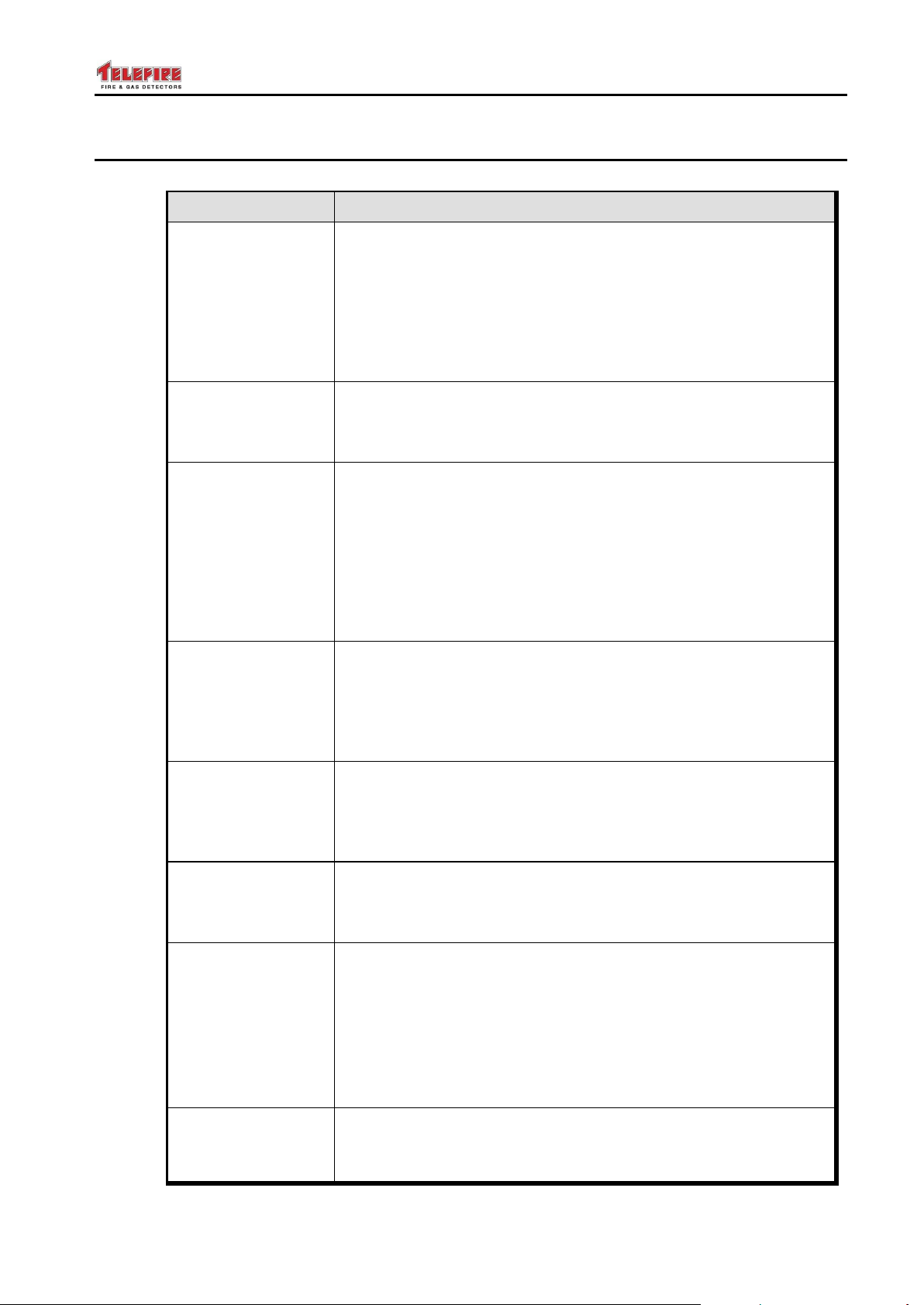
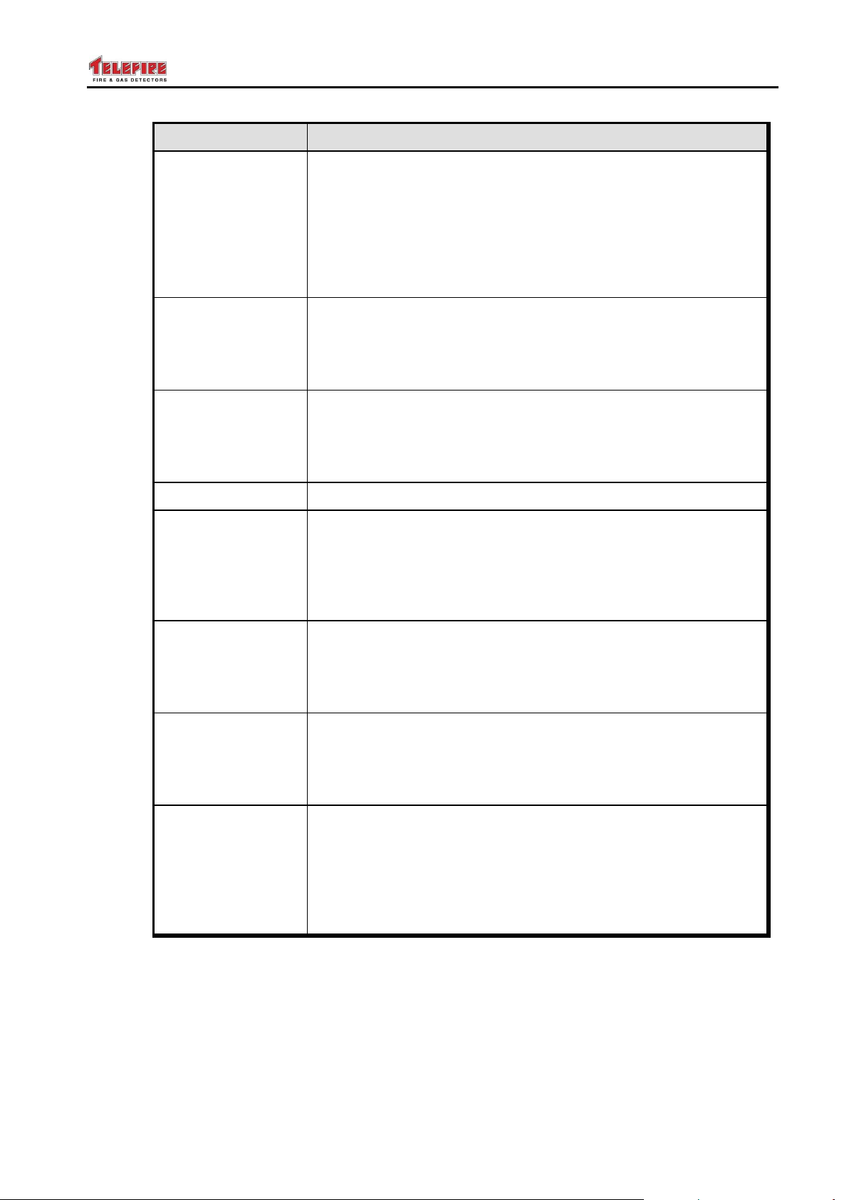
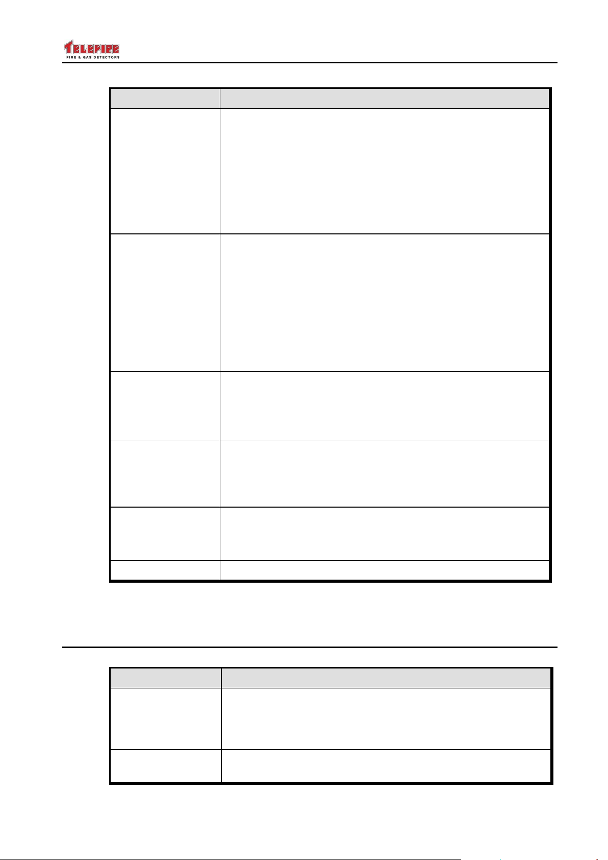
6.2 LEDs
– Page 34 of 87 –
Page 41
ADR-7000 / SAVER-7000 / GUARD-7
LED
Meaning
Aux 24V Fault
Yellow LED. Indicates a fault in the auxiliary 24Vdc outputs.
Additional detail is shown on the LCD display.
Off during normal operation
Flashes on upon a fault event in any output device (other
than Horn and outputs configured as "General, Silenced").
Pressing Acknowledge will turn the LED solid on until
resolution of the problem
Outputs Delayed
Yellow LED. Indicates that an output is delayed and will be
activated once the countdown period is over.
Off during normal operation
On during the countdown process
Abort
Yellow LED. Indicates an aborted extinguishing operation. Off
during normal operation
Off during normal operation
On following an abort
A
Reserved for future use
Fire
Red LED. Indicates fire alarm. The device in alarm is displayed
on the LCD display.
Off in normal state
Flashes during alarm. Pressing the Acknowledge key will
turn the LED on until the control panel is reset
Supervisory
Yellow LED. Indicates a supervisory event.
Off during normal operation
The LED flashes as long as the supervisory event is in
force.
Alarm Verify
Yellow LED. Indicates alarm verification. Also displayed on the
LCD display.
Off in normal operation
Flashes during alarm verification
Disabled
Yellow LED. Indicates a disabled input, or output. Additional
detail is shown on the LCD display.
Off during normal operation
On when one of the inputs or outputs is disabled.
Additional detail is shown on the LCD display. The LED will
stay on until all inputs, and outputs are enabled.
© 2017 – Telefire Fire & Gas Detectors Ltd Revision 0.98 October 2017
– Page 35 of 87 –
Page 42
ADR-7000 / SAVER-7000 / GUARD-7
LED
Meaning
Telecom Active
Yellow LED. Indicates a fault event in the dialer line.
Additionally a fault alert marks this event.
Off in normal operation
Solid on in red during dialing
Flashes in yellow when there is a fault event in the dialer.
Pressing the Acknowledge key will turn the LED on until
the fault is resolved
Solid yellow when the dialer is disabled.
Sounders Active
Red/Yellow LED. Indicates a situation where the horns are
disabled due to a fault in the horn line or disablement of the
horn output.
Off during normal operation
Slid on red during horn activation
Flashes in Yellow when there is a fault in the horn line.
Pressing Acknowledge will turn the LED solid on until
resolution of the problem
Solid yellow when horn output is disabled
Silenced
Red LED.
Yellow LED. Indicates silenced condition.
Off during normal operation and during alarm
Flashes during alarm after silencing.
Pre Discharge
Red LED. Indicates that an extinguishing output is delayed and
will be activated once the countdown period is over.
Off during normal operation
Flashes during the countdown process
Released
Red LED. Indicates that an extinguishing output was activated.
Off during normal operation
Flashes during the countdown process
B
Reserved for future use
Key
Function
Evacuate /
Resound
Allows the Operator to initiate an evacuation procedure.
Requires password.
If a sounders was silenced, pressing Resound renewal all
general sounders. Requires password.
Dialer
Allows the Operator to enable/disable the automatic dialer.
Requires password.
© 2017 – Telefire Fire & Gas Detectors Ltd Revision 0.98 October 2017
Table 1 Operator Panel – Indicating LEDs
6.3 Operator Keys
– Page 36 of 87 –
Page 43
ADR-7000 / SAVER-7000 / GUARD-7
Key
Function
Buzzer Off
Pressing this key silences only internal buzzer.
Recall Memory
In normal mode – used to scan through the existing events.
The top row of the LCD will show the recalled event number
and description. The total number of events will be
displayed on the lower right.
In program mode – moves the address to the next active
device.
Silence
Pressing this key silences the devices connected to the General
Alarm NAC (if defined as Silenced), HORN output, and all
addressable outputs that are defined as "silenced".
Reset
Pressing this key resets and restores the system to normal
operation mode. All NACs are turned off, input and output
modules return to normal operation mode, addressable
detectors receive a reset signal, the LCD displays "System OK"
and history report is updated. The system will resound if any
Alarm or Trouble occurs.
© 2017 – Telefire Fire & Gas Detectors Ltd Revision 0.98 October 2017
Table 2 Operator Panel – Operator Keys
6.4 Numerical and Arrow Keys
6.4.1 Numerical Keys
The numeric keys are used for entering values for system initialization, programming,
daily operation, password entering, and selecting menu field values on the LCD.
6.4.2 Arrow Keys
The arrow keys are used for navigating from field to field on the screen during system
programming and for browsing through the memory.
– Page 37 of 87 –
Page 44
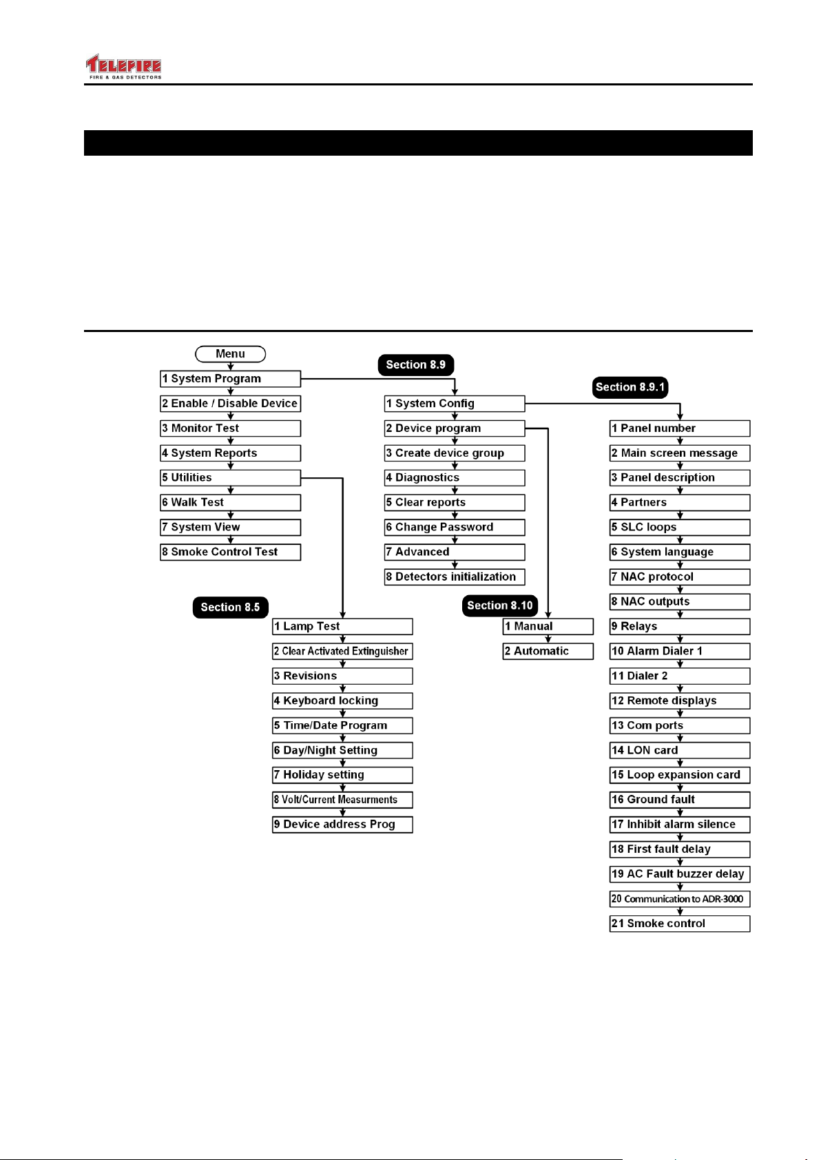
ADR-7000 / SAVER-7000 / GUARD-7
© 2017 – Telefire Fire & Gas Detectors Ltd Revision 0.98 October 2017
7 System Configuration (Programming) Process
The ADR-7000's site-specific data can be programmed and modified on site to respond
to each site's specific requirements.
ADR-3000 programming requires level 3 access.
After entering programming mode it is possible to set system configuration; program
devices, including alarm parameters and activation logic of NACs; create groups;
change passwords; and re-initialize detectors.
7.1 Menu Structure
Figure 16 Menu structure
– Page 38 of 87 –
Page 45
ADR-7000 / SAVER-7000 / GUARD-7
UL
UL 864 paragraph 59.1 Compliance
The ADR-7000 product family is UL 864 complaint, and does not allow setting
that contradict the standard's requirements.
The following products mentioned in this manual were not tested or listed by
UL and should not be installed where UL listing is required:
TFH-280A and TFH-220A (Heat Detectors)
ADR-812A and ADR-818A (Input modules)
TPS-34A (auxiliary power supply – use a UL listed 24Vdc power supply)
TIP-224A (Sounder)
ADR-833A (Extinguishing controller)
TPH-482A and TPH 442A (photo / heat multi-sensor detectors)
i
Note
After about 30 minutes without keyboard activity during programming mode
the control panel's buzzer is activated to remind you not to leave the system
in programming mode.
© 2017 – Telefire Fire & Gas Detectors Ltd Revision 0.98 October 2017
7.2 Entering Configuration State
Press Menu and select 1 System Program. Enter the password and press Enter.
7.3 Configuration Process
Programming the system is in five steps:
Enter programming state
Program control panel general setting
Program device-specific parameters for input devices
Program output devices / NACs operating mode and activation conditions
Save system configuration
7.4 Saving the Configuration and Exit Out of System Configuration
When exiting programming mode the control panel will display a menu with 3 choices:
1 – save and exit
2 – discard changes and exit
# – cancel exit and go back to programming
– Page 39 of 87 –
Select the desired option by pressing the appropriate key.
Page 46

ADR-7000 / SAVER-7000 / GUARD-7
UL 864
UL Requirement
UL 864 paragraph 36.1.7 states that "An automatic delay provided prior to
release operation by a system shall be a maximum of 60 seconds, timed from
a release initiation condition, either from the actuation of a single detector, or
from the actuation of the second circuit or detector for cross-zone and singlezone multiple-detector, or a combination of the two operations"
© 2017 – Telefire Fire & Gas Detectors Ltd Revision 0.98 October 2017
– Page 40 of 87 –
Page 47
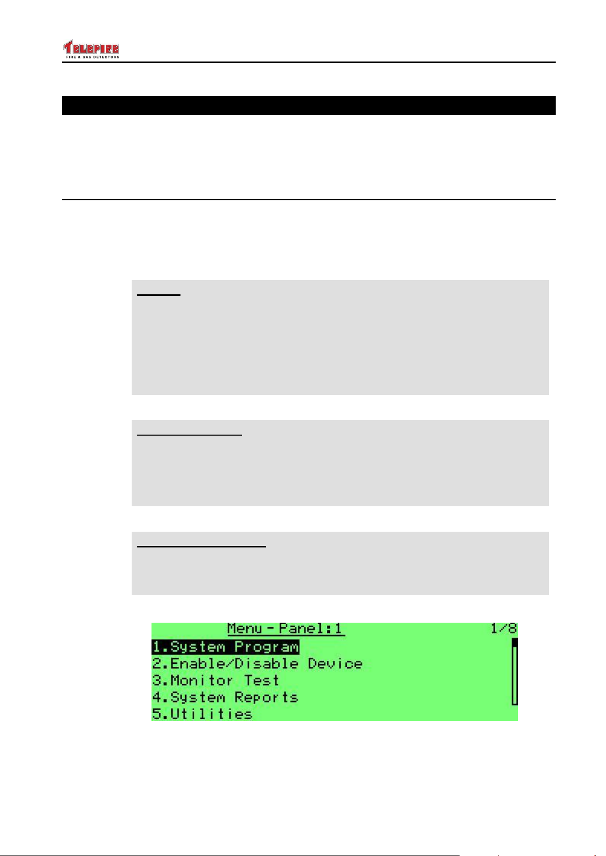
ADR-7000 / SAVER-7000 / GUARD-7
i
Note
Telefire's ADR-7000 product line complies with the requirements of several
standards, including UL 864, IS 1220, EN 54, EN 12094, and GOST, and
may comply with options or requirements of one of the standards and are not
compliant with another standard.
Where the control panel allows setting of a parameter that are outside the
range of one of the standards, we included an appropriate warning in the
relevant area of the manual.
UL 864
UL Requirement
UL 864 paragraph 36.1.7 states that "An automatic delay provided prior to
release operation by a system shall be a maximum of 60 seconds, timed from
a release initiation condition, either from the actuation of a single detector, or
from the actuation of the second circuit or detector for cross-zone and singlezone multiple-detector, or a combination of the two operations"
IS 1220
IS 1220 Requirement
Do not combine alarm verification utilizing delay and cross zone verification.
Total delay for activation of extinguishing (detector verification delay and
extinguishing activation delay) shall not exceed 60 seconds.
© 2017 – Telefire Fire & Gas Detectors Ltd Revision 0.98 October 2017
8 System Configuration (Programming)
Moving between fields is done with the ► and ◄ keys. Changing the field's value is
done with the ▲ and ▼ keys or by entering the value with the numeric keys.
You can select menus by entering the menu number or by scrolling with the ▲ and ▼
keys.
8.1 System Configuration
The system programming menu supports matching the system to the site requirements.
You can set the configure the system, program field devices, check reports, etc..
Please see sections 8.9 onwards starting on page 54 for a detailed explanation of the
system programming.
Screen 10 Main Menu (1 of 2)
– Page 41 of 87 –
Page 48
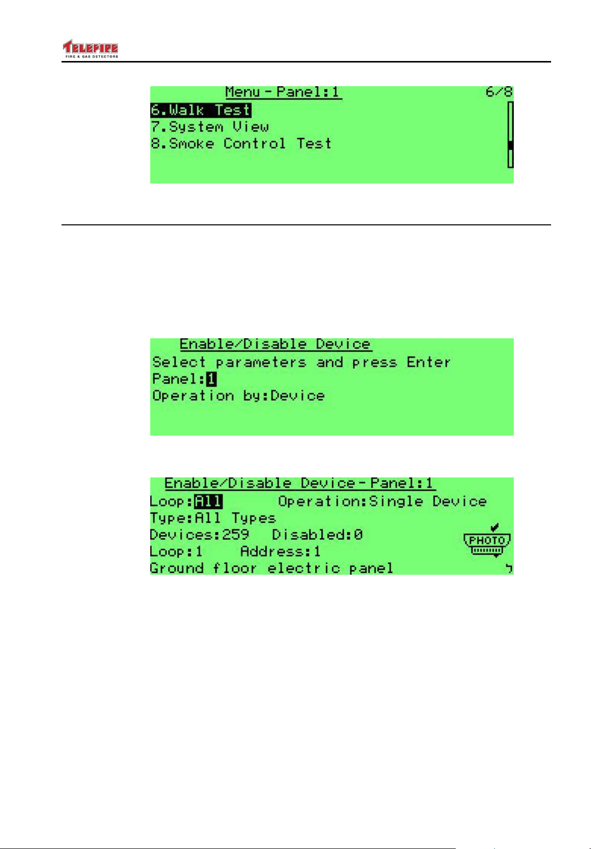
ADR-7000 / SAVER-7000 / GUARD-7
© 2017 – Telefire Fire & Gas Detectors Ltd Revision 0.98 October 2017
Screen 11 Main Menu (1 of 2)
8.2 Enablement / Disablement
8.2.1 Enabling and Disabling a Device
This function is used for temporary disabling a device. A disabled device shall not cause
any fault (with the exception of a Disablement notification); disable input devices shall
not cause an alarm and a disabled output device shall not be activated in case of alarm.
Press Menu to get to the main menu. Select 2. Enable/Disable Device. Select panel
number and whether the operation shall be performed for a device, a Zone, a Group, or
Main Board Outputs.
Screen 12 Enable / Disable primary screen
Press Enter and you can see the following screen:
Screen 13 Enable / Disable Device
Here you can select the device or devices that will be enabled or disabled:
Loop: all loops, or a specific loop (1-8)
Operation: single device or all devices with the following parameters:
Device Type: All Types, or all devices of the following type:
Photoelectric detectors
Heat detectors (select all modes, fixed temp or rate of rise)
Gas detectors
Input modules (all input modules or only those modules who cause the
following: Alarm input; Reset Switch; Silence; Disconnect; Supervisory; Abort;
Release; Alarm Matrix; or Fan FC)
– Page 42 of 87 –
Page 49
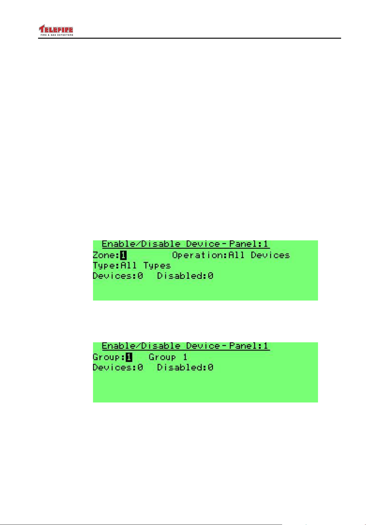
ADR-7000 / SAVER-7000 / GUARD-7
© 2017 – Telefire Fire & Gas Detectors Ltd Revision 0.98 October 2017
Switch (select All Modes; Reset Switch; Silence; Disconnect; Supervisory;
Abort; Release; Alarm Matrix; or Fan FC)
Power Supply
Sounder
Lamp
Extinguisher
Extinguisher Control
Control Output (select All Modes; Alarm; Fault; Fan; or Damper)
Isolator
CO / Heat Detector
Photo / Heat Detector
Supervisory Out
Fire Phone Jack
Fire Phone Lamp
SCM (select all modes; Fan / Damper; or Engage)
After selecting device type you can select the specific device address.
8.2.2 Enabling and Disabling a Zone
Selecting Operation by Zone shall display the following screen:
Screen 14 Enable / Disable Zone
This operation allows the disablement or enablement of devices in a specific logical
zone, rather than a physical loop. Device selection and criteria are identical to the
selection process by loop or address, as detailed in the previous paragraphs.
Screen 15 Enable / Disable Group
This operation allows the disablement or enablement of devices by group, rather than a
physical loop. Device selection and criteria are identical to the selection process by loop
or address, as detailed in the previous paragraphs.
– Page 43 of 87 –
Page 50
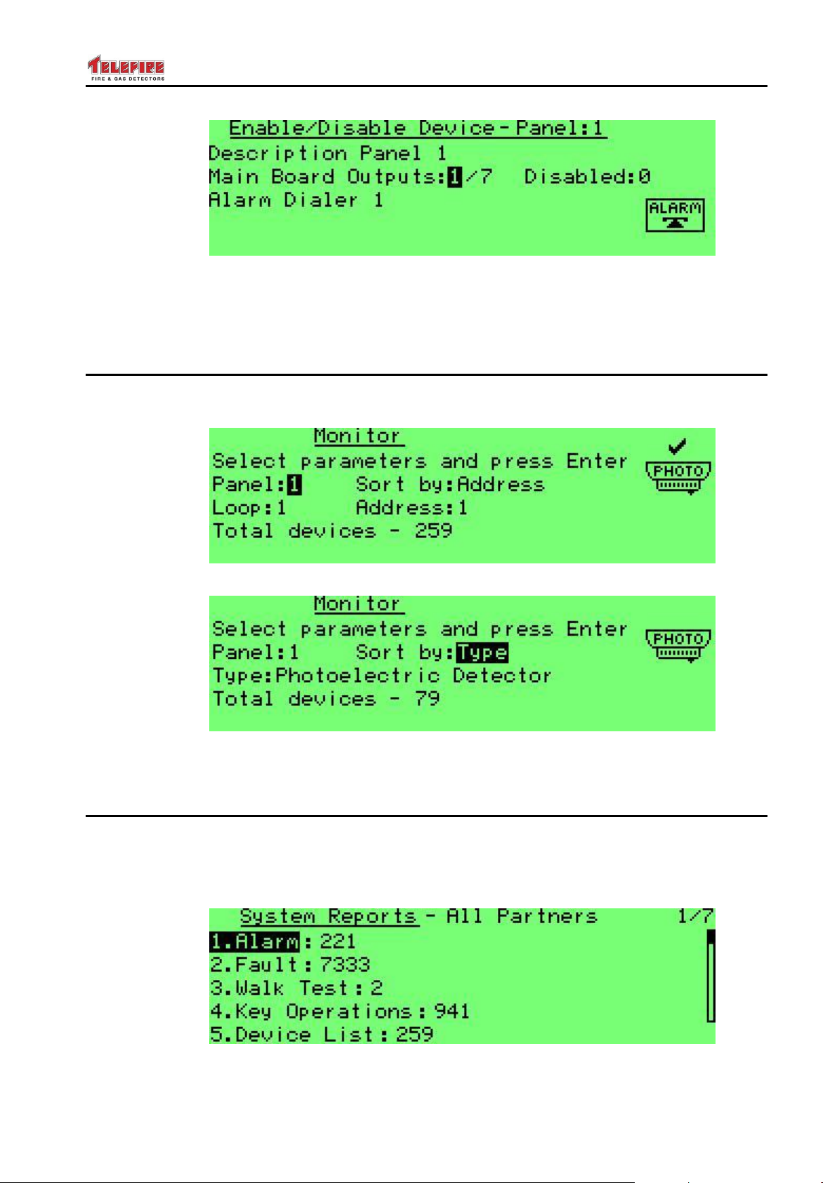
ADR-7000 / SAVER-7000 / GUARD-7
© 2017 – Telefire Fire & Gas Detectors Ltd Revision 0.98 October 2017
Screen 16 Enable / Disable Main Board Outputs
This operation allows the disablement or enablement of main board outputs (Alarm
Dialer; FWRE Dialer; NAC 1; NAC 2; Relay 1; Relay 2; or Relay 3), rather than a
physical loop. Select the specific device using the up / down arrows.
8.3 Monitor
The Monitor feature allows the graphic display of the physical sensor's output of a
selected device. You can also perform a test of the device.
Screen 17 Monitor Screen: Sort by Address
Screen 18 Monitor Screen: Sort by Type
Device selection is similar to device selection in Enable / Disable menu.
8.4 System Reports
System reports allows you to see a detailed report
The System Reports Menu allows you to get details on the number of sirens, faults,
testing the detectors in the field, key actions, the list of devices in the system, active
output circuits, and maintenance recommendations.
Screen 19 System reports
– Page 44 of 87 –
Page 51
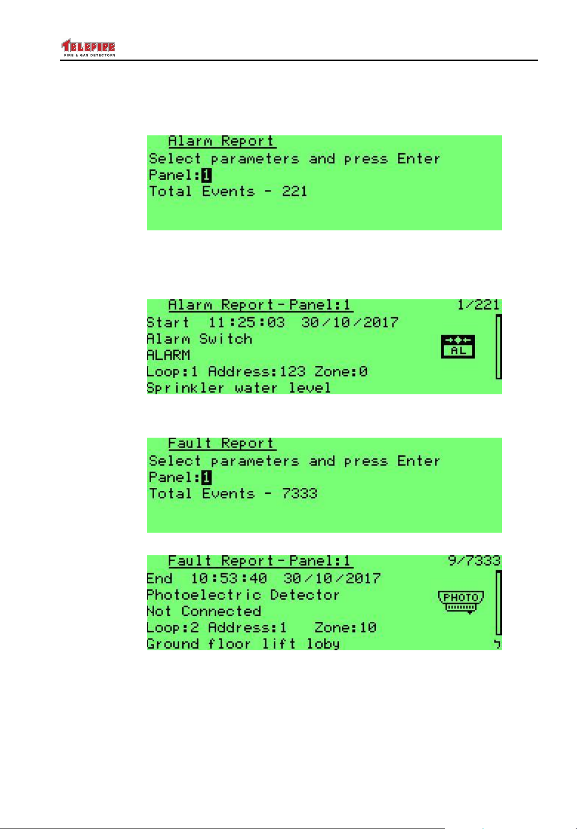
ADR-7000 / SAVER-7000 / GUARD-7
© 2017 – Telefire Fire & Gas Detectors Ltd Revision 0.98 October 2017
8.4.1 Alarms
System reports detail the number of alarms, faults, devices under test, key operations,
device list, active outputs and preventive maintenance recommendations.
Screen 20 System reports – alarms (panel selection)
After selecting the panel it is possible to page though individual alarms with the arrow
keys.
Screen 21 System reports – individual alarm
8.4.2 Faults
Screen 22 System reports – faults (panel selection)
Screen 23 System reports – individual fault
– Page 45 of 87 –
Page 52
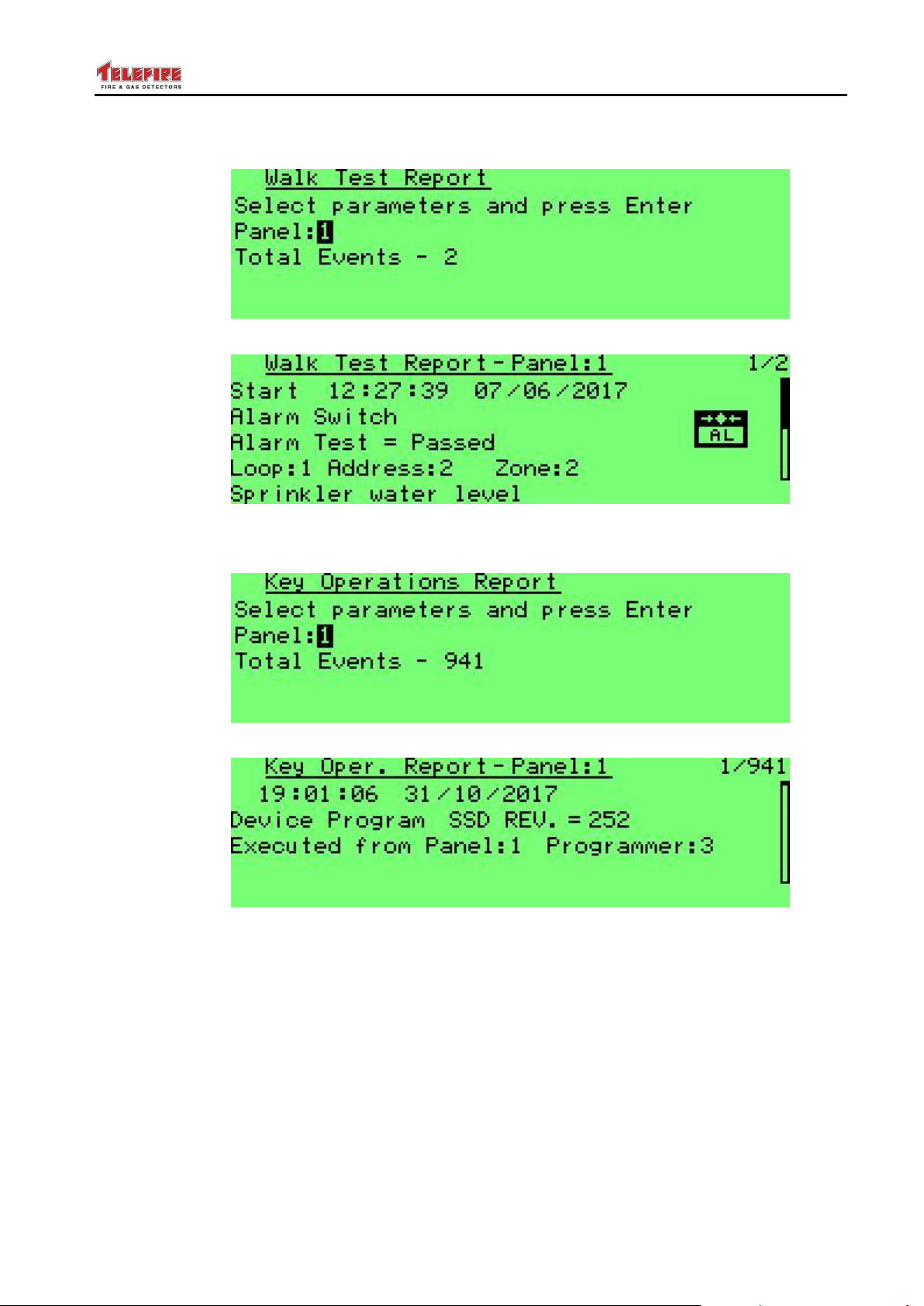
ADR-7000 / SAVER-7000 / GUARD-7
© 2017 – Telefire Fire & Gas Detectors Ltd Revision 0.98 October 2017
8.4.3 Field Test
Screen 24 System reports – walk test (panel selection)
Screen 25 System reports – individual walk test
8.4.4 Key Operations
Screen 26 System reports – Key Operations (panel selection)
Screen 27 System reports – individual key operation
Key Operation report displays activity reports for the following operations: panel
configuration; hardware initialization; advanced configuration; device programming;
creation of a device group; sounder silence; reset after an alarm; enablement or
disablement; evacuation; and time and date configuration.
The report will indicate whether the configuration change was done from a PC or the
control panel itself' and the identity of the person who performed this task).
– Page 46 of 87 –
Page 53
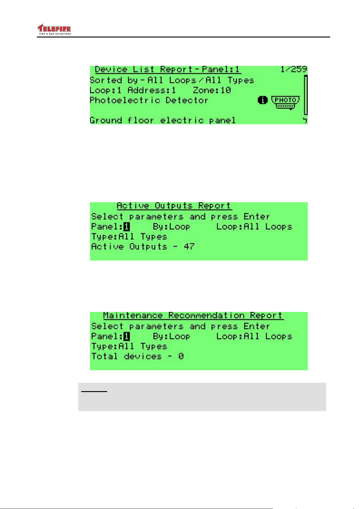
ADR-7000 / SAVER-7000 / GUARD-7
i
Note
It is recommended to replace detectors that are close to maintenance alarm
(detectors whose reference value – Vref – is equal or lower than 65).
© 2017 – Telefire Fire & Gas Detectors Ltd Revision 0.98 October 2017
8.4.5 Device Listing
Screen 28 System reports – device report
Device List report allows you to check device quantities. You can check all loops, a
specific loop, and either all devices or a specific device type, such as heat detector r
sounder. Selection is the same process used in enable / disable device.
8.4.6 Active Output
Active Outputs report indicates outputs that are active at the moment. You can select all
loops, a specific loop, and either all devices or a specific device type (sounder; Lamp;
Extinguisher; Extinguisher Control; Control Out; Supervisory Out; or Fire Phone Lamp).
Screen 29 System reports – active outputs
8.4.7 Maintenance Recommendations
Maintenance recommendation report lists all detectors that are close to maintenance
alarm. You can select all loops; a specific loop; a specific logical zone; and smoke
detectors, photo / heat detectors, or both.
Screen 30 System reports – Maintenance recommendation
– Page 47 of 87 –
Page 54
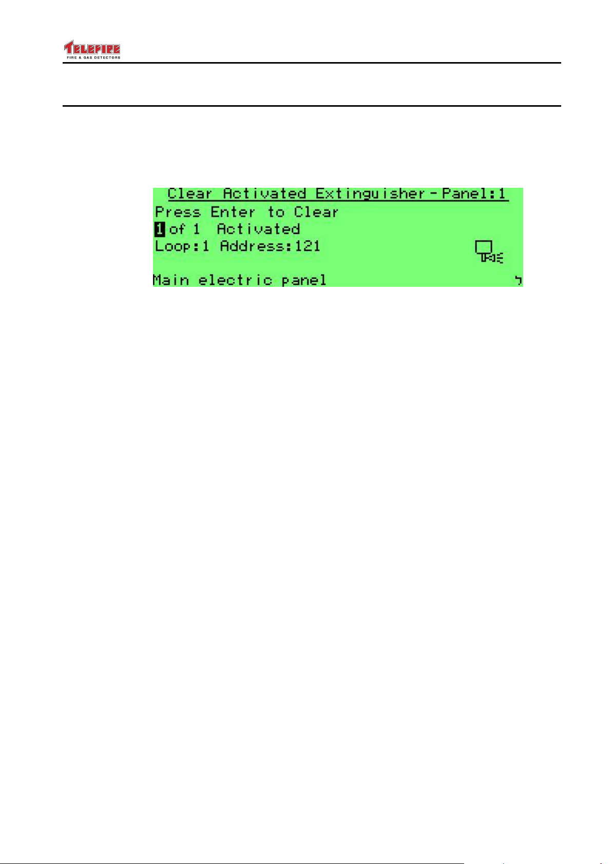
ADR-7000 / SAVER-7000 / GUARD-7
© 2017 – Telefire Fire & Gas Detectors Ltd Revision 0.98 October 2017
8.5 Utilities
8.5.1 Lamp Test
Lamp test turns on all LEDs in the keyboard / display and activates the internal buzzers
for a few seconds.
8.5.2 Clear Activated Extinguisher
Screen 31 Clearing Extinguishing activated indication
Activation of an extinguishing output will result in a notification in the control panel that
extinguishing was activated. Pressing the Reset key will not cancel this indication in
order to ensure extinguishing agent replacement or refill.
To return the control panel to normal operation refill or replace the extinguishing device,
select the clear activated Extinguisher menu by pressing Menu, selecting 5 Utilities,
and selecting 2 Clear Activated Extinguisher. Press Enter and ensure that the control
panel is back to Quiescence state.
This operation shall be performed only by authorized personnel.
8.5.3 Revisions
This option shall display hardware and software revisions of the following modules:
1. CPU Card (ADR-7007)
2. SLC cards (ADR-7002)
3. Main Board (ADR-7021)
4. Display Card (ADR-7003)
5. LON Card (LON-7000)
6. TCP/IP Net Card (NET-7000)
7. Remote Displays (RM-7000)
8. Site Specific Data – Device Configuration
9. Site Specific Data – System Configuration
8.5.4 Keyboard Locking
The Keyboard Locking function prevents unauthorized people from activating functions
by pressing accidentally the operator keys such as silencing an alarm or reset.
When the keyboard is locked, no action can be taken in the system, except
acknowledge, browsing the memory and displaying alarm and trouble events.
The ADR-7000 default configuration is locked keyboard.
To change the keyboard locking mode, go to the Utilities menu and select Keyboard
Locking. You will need to enter the programmer password to access this submenu.
The Up/Down arrow keys change the locking mode.
Changing to Unlocked mode enables the operator/programmer access to silence and
reset functions without entering a password.
The keyboard will stay unlocked until the control panel is powered off.
– Page 48 of 87 –
Page 55
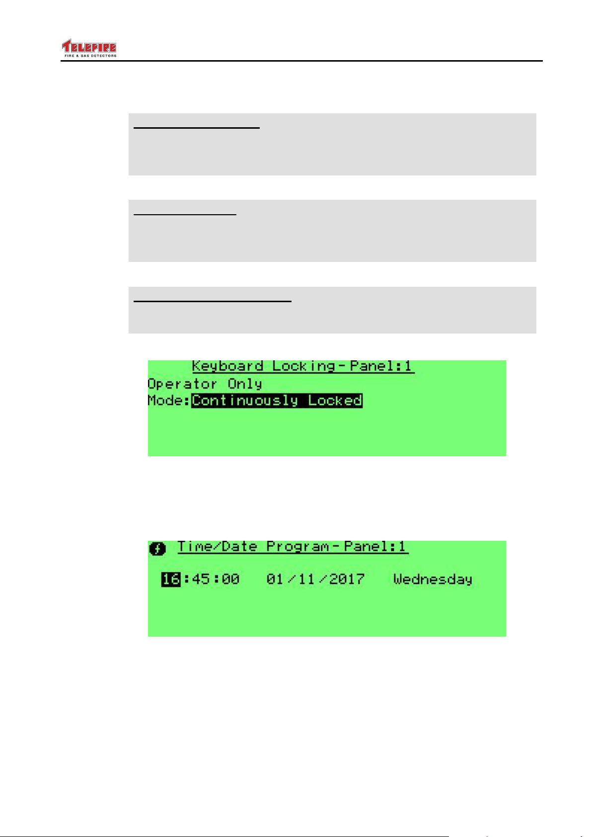
ADR-7000 / SAVER-7000 / GUARD-7
IS 1220
IS 1220 Requirement
IS 1220 requires that auto lock timeout shall not exceed 30 minutes.
Set to auto lock continuously, 10 minutes, or 30 minutes to comply with
IS 1220 requirement.
UL
UL Requirement
UL 864 requires that auto lock timeout shall not exceed 30 minutes.
Set to auto lock continuously, 10 minutes, or 30 minutes to comply with
UL requirement.
NFPA 72
NFPA 72 Recommendation
NFPA recommendation and local regulations in most countries require that
the keyboard be locked.
© 2017 – Telefire Fire & Gas Detectors Ltd Revision 0.98 October 2017
The keyboard can be configured to auto-lock continuously, 10 minutes, 30 minutes, or
one hour after last use.
Screen 32 Keyboard Locking – mode selection
8.5.5 Time / Date Program
Use this menu to set the date and time. Press Function and 1 to copy this value to
other panels on the network. Only those panels that are configured as Partner shall be
updated.
Screen 33 Setting time and date (date is European style – day / month / year)
8.5.6 Day / Night Setting
Here you can set whether the control panel shall work in a time-based
This sub-menu serves for setting system operating modes, by different time settings, to
distinguish between normal operating hours (Day mode) and nighttime hours (Night
mode).
Mode – This field indicates one of three operating modes.
Day – Continuous operation in day mode (without automatic change).
– Page 49 of 87 –
Page 56
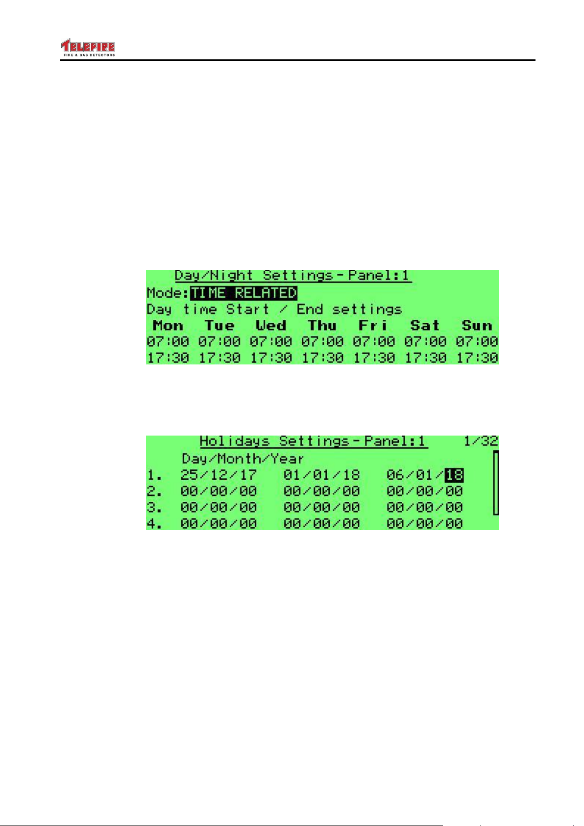
ADR-7000 / SAVER-7000 / GUARD-7
© 2017 – Telefire Fire & Gas Detectors Ltd Revision 0.98 October 2017
Night – Continuous operation in night mode (without automatic change).
Time-Related – Automatic shifting from Day to Night mode and vice versa,
according to time settings.
Select one of the modes by using the Up / Down keys. At Time-Related mode, each
weekday can be programmed by selecting a day and then setting the nighttime between
night start and night end.
Different time settings can be set for each day of the week. Use the arrow keys to toggle
between fields.
Detector sensitivity will change according to the day and night sensitivity settings of each
detector.
The Day / Night modes also affect dialer operation. An alarm that occurs during night
mode will activate the dialer immediately. During day mode operation will be delayed if
programmed thus.
Screen 34 Setting daily night and day times
8.5.7 Holidays Setting
Here you can define public holiday (referred to in some countries as "national holidays"
or "bank holidays") dates. The cont4rol panel shall work as nighttime mode all day.
Screen 35 Setting holiday dates
8.5.8 Volt / Current Measurements
Allow measuring voltages and currents in the control panel:
1. Power and battery: power supply voltage; battery voltage; battery charging current;
charging cycle.
2. NAC Outputs: NAC 1 and NAC 2 voltages and current
3. 24Vdc Outputs – Main board: 24V_A and 24V_B, and Dialer output voltages and
current
4. 24Vdc Outputs – Loop expansion board: 24V_C and 24V_D voltages and current
5. Loop cards: input voltage and current draw
6. Alarm Dialer: voltage and current
7. Fault Dialer: voltage and current
8. Ground Fault graph
– Page 50 of 87 –
Page 57

ADR-7000 / SAVER-7000 / GUARD-7
© 2017 – Telefire Fire & Gas Detectors Ltd Revision 0.98 October 2017
9. 3V Battery: battery voltage (this battery is used for configuration back up when the
control panel is powered off)
10. Total current: total current from all 24Vdc outputs; both NACs and all loops
11. Temperature: main board temperature
12. RM Control:
13. RM Control:
14. RM Control:
15. LON Net Diagnostic: LON communication diagnostics (communication between
control panels in a network)
16. I2C Diagnostics: I2C communication diagnostics (this is the internal communication
between in the control panel)
8.5.9 Device Address Programming
Allows address programming to a detector that is connected to J28 on the main board.
Manual – set an address to each detector
Automatic – increases the address by 1 after each address setting.
8.6 Walk Test
This feature allows the testing of all the initiating devices of the system.
The device test is performed by placing a magnet near the detector’s test point or by
activating the alarm call-points with the test key (supplied with the call-points).
Entering the Walk Test mode is done through the main menu and requires a password.
From the main menu select 6 Walk Test. The following message is displayed:
Key in 1 to select devices for testing. The next menu shall allow the selection of loops;
zones; or groups for testing. Press Enable to add the devices to be tested. Press Exit
and save changes.
The Walk Test LED shall turn on to indicate that a walk test is currently done.
Start testing by initiating the devices. Upon activation of the device, the device alarm
indicating LED will light and the device address will be displayed on the LCD. After 15
seconds the system will perform automatic reset to the device. During the automatic test
no outputs are activated.
An alarm received from a device that is not in Walk Test mode will abort the Walk Test
will activate the alarm.
Two simultaneously alarms from the tested card will abort the Walk Test procedure and
activate the alarm.
A device that is programmed as delayed will respond to the test immediately.
To stop the automatic test process, press the Quit key.
When you complete the testing go to the Walk Test menu and define the devices as
normal operation again.
The system aborts the walk test and returns to normal operation if no devices are tested
for 15 minutes.
8.6.1 Select Devices
Select the loops for testing. Press Enable while selecting the Test field to change field
value from Test Disabled to Test Enabled.
– Page 51 of 87 –
Page 58
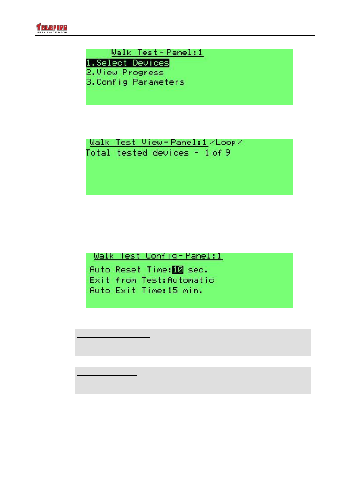
ADR-7000 / SAVER-7000 / GUARD-7
IS 1220
IS 1220 Requirement
IS 1220 requires that exit from Walk Test shall be automatic and within 30
minutes. Ensure you change this setting to comply with IS 1220.
UL
UL Requirement
UL 864 requires that exit from Walk Test shall be automatic and within 30
minutes. Ensure you change this setting to comply with UL 864.
© 2017 – Telefire Fire & Gas Detectors Ltd Revision 0.98 October 2017
Screen 36 Walk test – main screen
8.6.2 View Progress
Selection option 2 View Progress shall show the total number of devices tested.
Screen 37 Walk test – progress report
8.6.3 Config Parameters
This menu allows setting the time until automatic reset during walk test (options are one
second to 30 seconds in 1 second steps. Default: 10 seconds).
It is also possible to set the exit from test mode to be either manual (default) or
automatic (5 to 60 minutes, default: 15 minutes).
Screen 38 Walk test parameter
– Page 52 of 87 –
Page 59
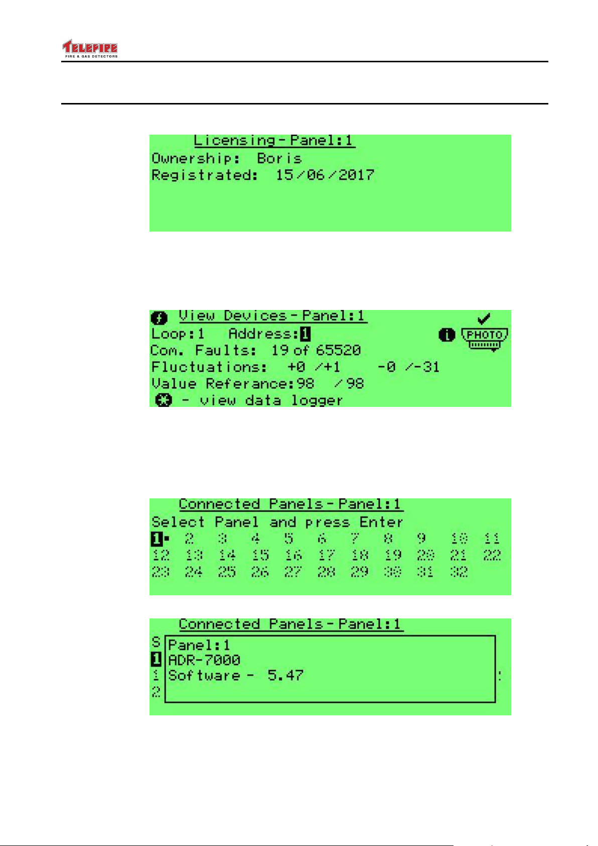
ADR-7000 / SAVER-7000 / GUARD-7
© 2017 – Telefire Fire & Gas Detectors Ltd Revision 0.98 October 2017
8.7 System View
8.7.1 Licensing
Screen 39 System view – panel licensing
See section 4.5.1 on page 28 for explanation about panel registration.
8.7.2 View Devices
Screen 40 System view – view devices
Pressing the Function key will allow to clear the selected device (1) or all devices (2).
You can return to screen 42 by pressing Quit.
8.7.3 Connected Panels
Screen 41 Connected panels
Screen 42 Connected panels – panel details
– Page 53 of 87 –
Page 60
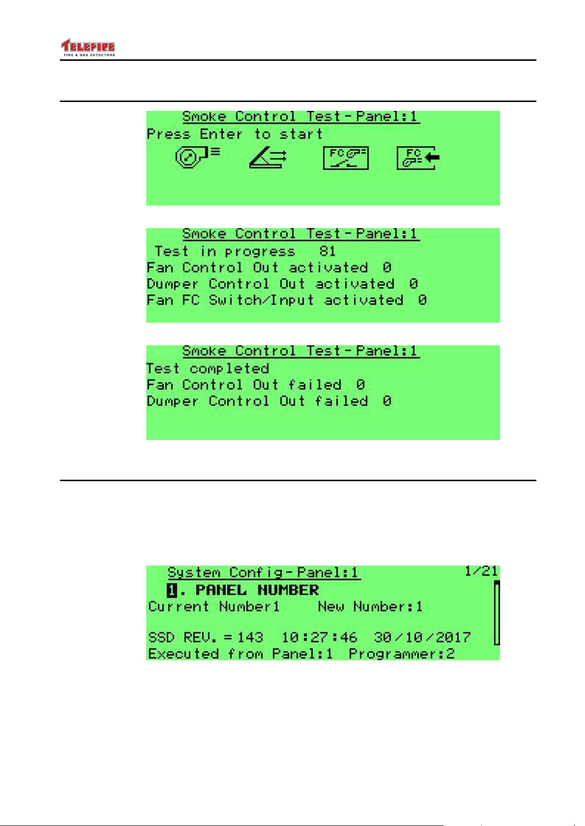
ADR-7000 / SAVER-7000 / GUARD-7
© 2017 – Telefire Fire & Gas Detectors Ltd Revision 0.98 October 2017
8.8 Smoke Control Test
Screen 43 Smoke control test
Screen 44 Smoke control test – test progress
Screen 45 Smoke control test – test report
8.9 System Configuration
This menu allows you to define the behavior of the control panel so that it matches the
specific site requirements.
8.9.1 Panel Number
This menu allows you to change the panel number when working in a networked system.
Select a number from 1 to 32.
Screen 46 System configuration – panel number
Panel No. 1 sets time synchronization to all the panels that are networked via the
LON-7000 module. Make sure one of the panels is set to be No. 1.
SSD Revision (SSD = Site Specific Data) indicates the revision number of control panel
configuration. This number increases by 1 every time the control panel configuration is
updated.
– Page 54 of 87 –
Page 61
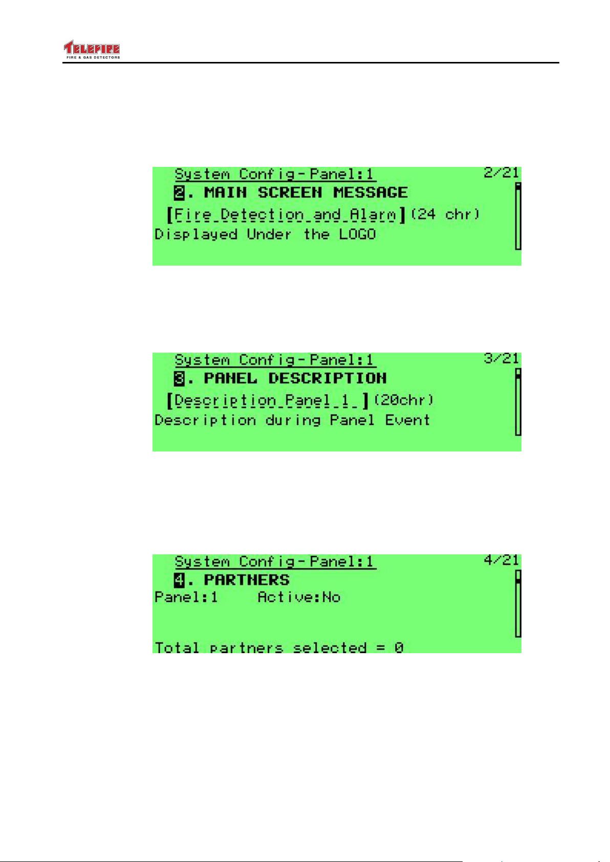
ADR-7000 / SAVER-7000 / GUARD-7
© 2017 – Telefire Fire & Gas Detectors Ltd Revision 0.98 October 2017
8.9.2 Main Screen Message
This option allows to change the message that is displayed under the Telefire logo. You
can key in up to 24 characters to indicate the service company name or phone number.
Use the arrow keys to select each character and Enter to key it in. Quit and save to
keep the new message.
Screen 47 System configuration – main screen message
8.9.3 Panel Description
Used to key a 20 character panel description, such as "Panel 3, manufacturing". This
will be displayed for system faults (such as batteries, ground fault, and AC fault) when
pressing the Info key.
Screen 48 System configuration – panel description
8.9.4 Partners
A networked control panel shall display alarms, faults, and other events that occur on its
partners. Configure the other panel as Active on the current panel to display events.
The following screen shows Panel 2 as an active partner to panel 1 (that is, panel 2
alarms will be displayed on panel 1 as well).
Screen 49 System configuration – partners
Once a panel is selected as partner, you can select which actions can be performed on
the partner panel.
In the example above all events from panel 2 shall be displayed on the current panel (1).
Perfuming Evacuation, Reset, and Silence in panel 1 shall be performed on panel 2 as
well.
– Page 55 of 87 –
Page 62
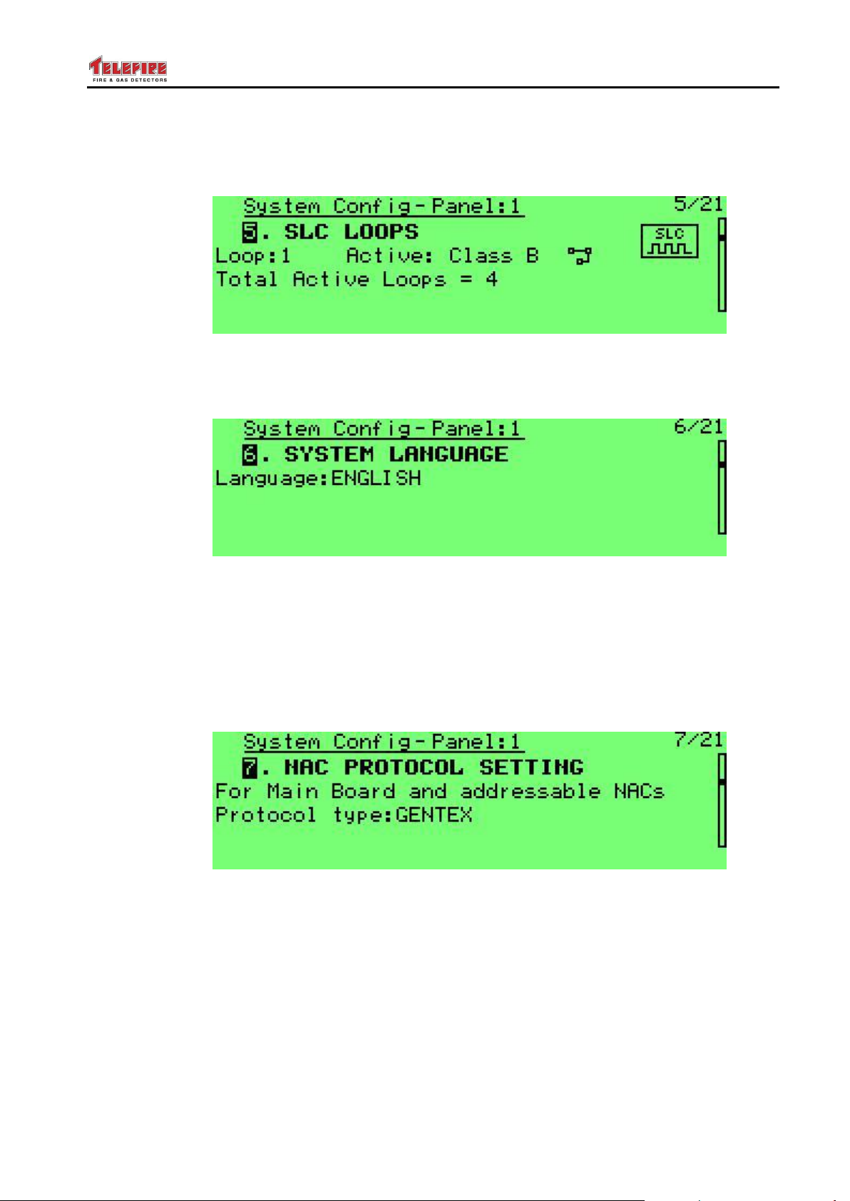
ADR-7000 / SAVER-7000 / GUARD-7
© 2017 – Telefire Fire & Gas Detectors Ltd Revision 0.98 October 2017
8.9.5 SLC Loops
You can define each loop as active or inactive (Active: No), or working in either Class B
or Class A. You can also see the number of loops defined in the panel.
Screen 50 System configuration – SLC Loops
8.9.6 System Language
This will allow you to change between system languages configured in the control panel.
Screen 51 System configuration – system language
8.9.7 NAC Protocol Setting
Here you can select whether NAC outputs shall work in Gentex or Wheelock protocol.
Both system NACs (NAC 1 and NAC 2) and ADR-723 outputs that are configured to
work in protocol operation (jumper setting on the ADR-723) shall work in this protocol.
This protocol synchronizes strobes throughout the system and allows the connection of
a sounder/strobe via 2-wires to the output. When the control panel is silenced, the
sounders shall stop working, but the strobes shall keep on flashing until reset.
Screen 52 System configuration – NAC protocol selection
8.9.8 NAC Outputs
Here you can configure the parameters for NAC 1 and NAC 2. Each can be configured
as Silenced (i.e., will stop operating when the control panel is silenced) or Unsilenced,
(i.e., will continue operating until the control panel is reset). You can also define whether
it operates as a standard output (No Protocol) or with the control panel's protocol
(defined above).
– Page 56 of 87 –
Page 63
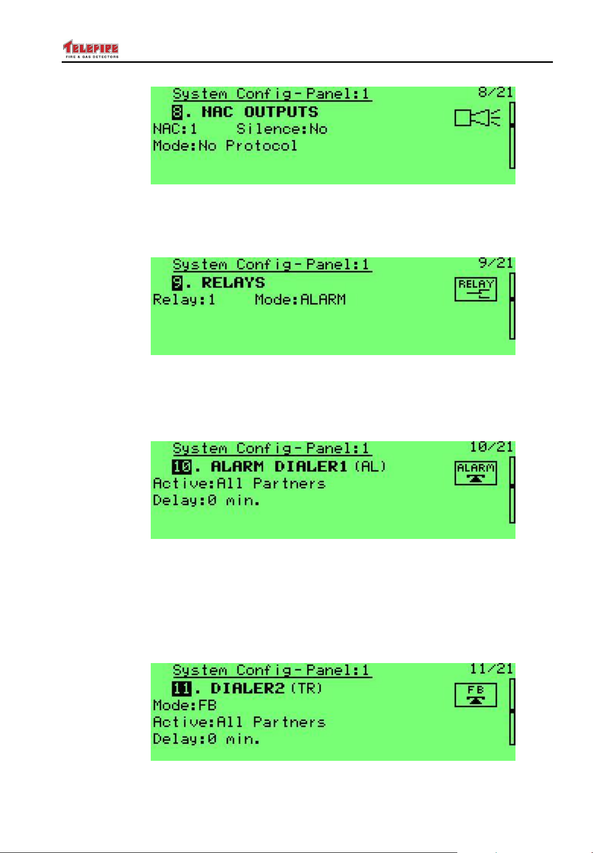
ADR-7000 / SAVER-7000 / GUARD-7
© 2017 – Telefire Fire & Gas Detectors Ltd Revision 0.98 October 2017
Screen 53 System configuration – NAC output
8.9.9 Relays
This menu allows you to configure the operation of the main board's 3 relays. You can
select between Alarm, Supervisory, Fault, and Pre-Alarm.
Screen 54 System configuration – relays
8.9.10 Alarm Dialer 1
This menu allows you to configure the alarm dialer's activation conditions: will it be
activated by any panel on the network that is defined as Partner or only from this panel;
and the activation delay during day time hours (0 – 9 minutes, in 1 minute increments).
Screen 55 System configuration – alarm dialer 1
8.9.11 Dialer 2 (Tr)
This menu allows you to configure the FWRE dialer's activation conditions: will it work as
in FWRE model (Fault Warning Router Equipment – in this mode it is always on and
switches off at any fault), or in FB mode (activated by either 2 detectors or any call
point); will it be activated by any panel on the network that is defined as Partner or only
from this panel; and the activation delay during day time hours (0 – 9 minutes, in 1
minute increments).
Screen 56 System configuration – alarm dialer 2
– Page 57 of 87 –
Page 64
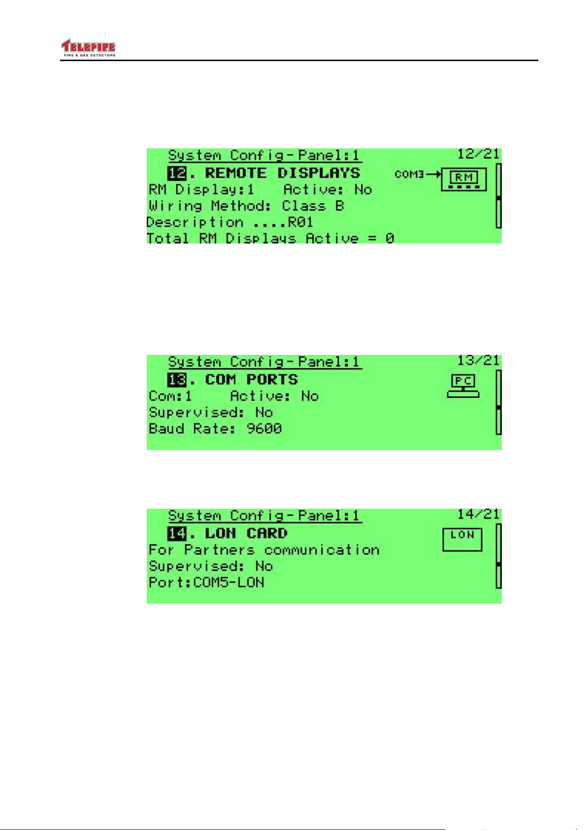
ADR-7000 / SAVER-7000 / GUARD-7
© 2017 – Telefire Fire & Gas Detectors Ltd Revision 0.98 October 2017
8.9.12 Remote Displays
This menu configures the RM-7000 remote anunciators. You can select whether each of
the 16 RM-7000 is active or not; Class A or Class B wiring; and assign a 19 character
description to each RM-7000.
Screen 57 System configuration – remote displays
8.9.13 COM Ports
This menu allows you to select the operation mode of COM1, COM2, and COM5 as
inactive, active an PC communication or NET-7000 TCP/IP interface; whether the
communication is supervised or not; and Baud rate.
COM3 and COM4 are used as RM-7000 connections and can't be configured other than
Class B or Class A operation (see above).
Screen 58 System configuration – com ports
8.9.14 LON Card
This menu allows the configuration of the LON-7000 port.
Screen 59 System configuration – LON cards
8.9.15 Loop Expansion Card
This menu allows you to configure whether an ADR-7022 SLC Expansion Module (for
loops 5 – 8) is installed.
– Page 58 of 87 –
Page 65
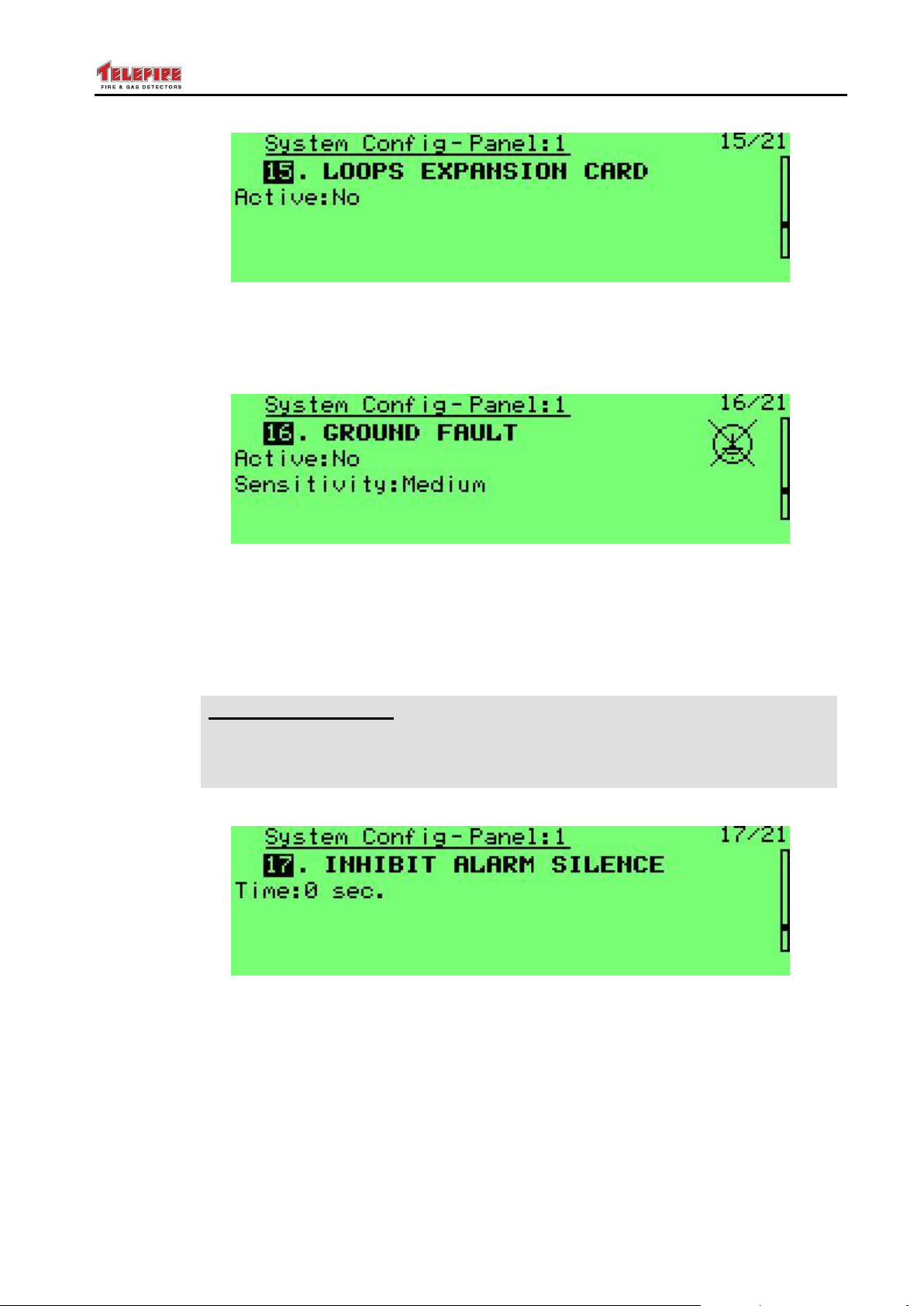
ADR-7000 / SAVER-7000 / GUARD-7
CP 10
CP 10 Requirement
CP 10 requires that under certain conditions alarms should not be silenced
for 3 minutes after first alarm. Change this value to 180 seconds if your local
standard requires it.
© 2017 – Telefire Fire & Gas Detectors Ltd Revision 0.98 October 2017
Screen 60 System configuration – loop expansion card
8.9.16 Ground Fault
This menu allows you to change the control panel's sensitivity to ground faults, or
disable it completely.
Screen 61 System configuration – ground fault
8.9.17 Inhibit Alarm Silence
This menu allows disabling the option to silence alarms for a certain time after alarm
initiation. Leave this option at the default unless required by local standard, regulation,
or authority having jurisdiction.
Screen 62 System configuration – inhibit alarm silence
8.9.18 First Fault Delay
This menu allows delaying first fault indication of addressable devices for a short time to
avoid temporary faults. Applies only to first fault – repeat faults will be displayed
immediately.
Range: 0 – 240 seconds. Default: 0 seconds.
– Page 59 of 87 –
Page 66
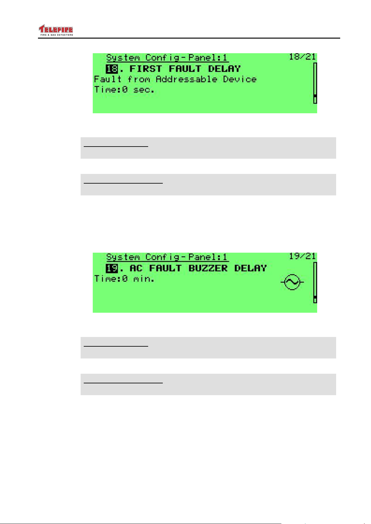
ADR-7000 / SAVER-7000 / GUARD-7
UL
UL Requirement
UL 864 compliance requires this value to be less than 180 seconds.
IS 1220
IS 1220 Requirement
IS 1220 compliance requires this value to be less than 180 seconds.
UL
UL Requirement
UL 864 compliance requires this value to be less than 180 seconds.
IS 1220
IS 1220 Requirement
IS 1220 compliance requires this value to be less than 180 seconds.
© 2017 – Telefire Fire & Gas Detectors Ltd Revision 0.98 October 2017
Screen 63 System configuration – first fault delay
8.9.19 AC Fault Buzzer Delay
This menu allows to delay activating the fault buzzer in case of loss of AC mains supply.
The fault is indicated visually immediately, regardless of this delay.
Range: 0 – 240 minutes. Default: 0 minutes.
Screen 64 System configuration – AC fault buzzer delay
8.9.20 Communication with ADR-3000
When set to Yes (default) the control panel shall warn that passwords were not changed
from the factory set defaults. Warnings start a month after first installation and will
repeat any time a password is required.
– Page 60 of 87 –
Page 67
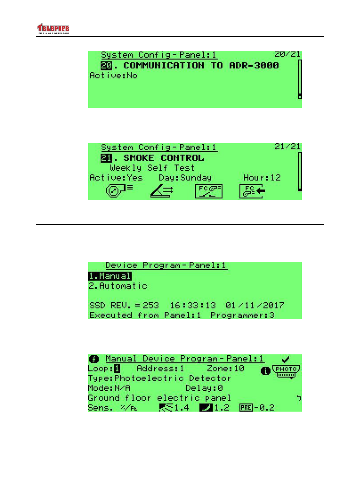
ADR-7000 / SAVER-7000 / GUARD-7
© 2017 – Telefire Fire & Gas Detectors Ltd Revision 0.98 October 2017
Screen 65 System configuration – communication with ADR-3000
8.9.21 Smoke Control
Allows to set the day and time of weekly Smoke Control system test.
Screen 66 System configuration – Smoke control test settings
8.10 Device Program
Select manual or automatic operation. Manual shall allow you to set parameters for a
specific address. Manual shall scan through each possible address at each SLC Line
Card. Each existing device shall be configured with the device's default setting, if it was
not previously configured.
Screen 67 Device programming – main screen
8.10.1 Manual Device Programming
This option allows you to set device parameters manually.
Screen 68 System configuration – manual device program
Loop: loop number (1 – 8)
Address: device address (1 – 127)
Zone: Logical Zone (1 – 511) of the device
– Page 61 of 87 –
Page 68

ADR-7000 / SAVER-7000 / GUARD-7
i
Note
A supervisory input or switch and its related supervisory out should be in the
same logical zone.
© 2017 – Telefire Fire & Gas Detectors Ltd Revision 0.98 October 2017
Device Type: the device type as follows:
Photoelectric Detector: (TFO-480A or TFO-440A)
Heat Detector: (TFH-280A or TFH-220A). Detector mode (Fixed Temperature
(default) or Rate of Rise) is defined in the Mode field.
Gas Detector: reserved for future use
Input Module (ADR-712; ADR-718; ADR-812A or ADR-818A). Mode can be
Alarm; Reset; Silence; Disconnect; Supervisory; Abort; Release; Alarm Matrix;
or Fan PC).
Switch: (a manual call point (TPB-800ASR, TPB-800ASY, or TPB-101ASM),
an input of an ADR-805A or ADR-705; or the IDC input or an ADR-723 or
ADR-823A). Switch operating mode is defined in the Mode field, and can be
Alarm; Reset; Silence; Disconnect; Supervisory; Abort; Release; Alarm Matrix;
or Fan PC.
Power supply: an auxiliary power supply (TPS-34A)
Sounder (TIP-224A, or an ADR-723 or ADR-823A output that activates
sounders). Operation mode is defined in the Mode field and can be No
Protocol or with the Control Panel's protocol.
Lamp: an ADR-723 or ADR-823A output that activates a strobe
Extinguisher: an ADR-723 output that is used to release extinguishant. The
Mode field specifies pulse length (5 seconds to 239 minutes, or continuous until
reset). Default is 15 seconds.
Extinguisher Control: (ADR-833A).
Control Out: the output of an ADR-723 or ADR-823A; or the relay of an
ADR-723, ADR-823A, or an ADR-741). The Mode field defines whether it is
activated by an alarm or a fault.
Isolator: an addressable line isolation module (LI-3000)
CO & Heat Detector: reserved for future use
Photo & Heat Detector: (TPH-482A or TPH-442A)
Supervisory Out: the output of an ADR-723 or ADR-823A; or the relay of an
ADR-723, ADR-823A, or an ADR-741 that is activated as a result of a
Supervisory event.
Fire Phone Jack: (TFP-806)
Fire Phone Lamp: (and address of a TFP-828)
SCM: the relay of an ADR-723, or an ADR-741 that is intended to activate or
stop a smoke control blower.
Zone: the device's logical zone. Can be in the range of 1 – 511.
Mode: the device's operating mode, device dependent.
For heat detectors: fixed temperature or rate of rise
For Input module: Alarm; Reset; Silence; Disconnect; Supervisory; Abort;
Release; Alarm Matrix; or Fan PC
– Page 62 of 87 –
Page 69

ADR-7000 / SAVER-7000 / GUARD-7
i
Note
An input module or switch that are configured as Alarm Matrix will activate a
matrix output even if it requires two or more alarms to activate.
© 2017 – Telefire Fire & Gas Detectors Ltd Revision 0.98 October 2017
For switches: Alarm; Reset; Silence; Disconnect; Supervisory; Abort; Release;
Alarm Matrix; or Fan PC
For sounder / strobe: whether this NAC works as the protocol that is defined in
the control panel or without protocol.
For extinguishers: the extinguishing pulse length
N/A for all other devices
Delay: alarm verification time for detectors, or an output activation delay. Can be
between 0 and 50 seconds.
Silenced: whether this output is silenced
0: not silenced
1: silenced; re-activated by any alarm
2: silenced; re-activated only by devices in this output's matrix
Event Control: activation conditions:
General: activated by any alarm
Device Matrix: a group of input devices should be selected to form a matrix in
order to activate the configured output device. The number of devices in alarm
required to activate the output device must be set between 1 (default) and 6.
Zone Matrix: A Zone Matrix is an activation array of one or several logical
device zones that are assigned to an output device in order to form complex
activation functions.
Alarms from all selected zones: number of alarms from any device in any
of the selected zones (i.e., 2 selected alarms from zones 1, 2, and 3 would
be activated by any 2 alarms from any 2 devices in zones 1, 2, and 3).
Alarms in a selected zone: number of alarms from any device in one of
the selected zones (i.e., both alarms need to be in the same zone).
Zones in alarm: number of zones out of the selected sets that need to be
in alarm (i.e., "2 zones in alarm" from zones 1, 2, and 3) requires that at
least one device in each of two separate zones be in alarm.
8.10.2 Automatic Device Programming
Automatic device programming causes the control panel to scan every possible address
and populate its device map according to whatever devices are installed.
Every connected device shall be configured as “Active” and with the correct device type
and the default configuration of that device type.
Setting logical zones, activation matrices, and other parameters requires operator
intervention (manual programming).
This will allow comparing the system as installed to planned configuration in order to find
any installation-related problems.
– Page 63 of 87 –
Page 70
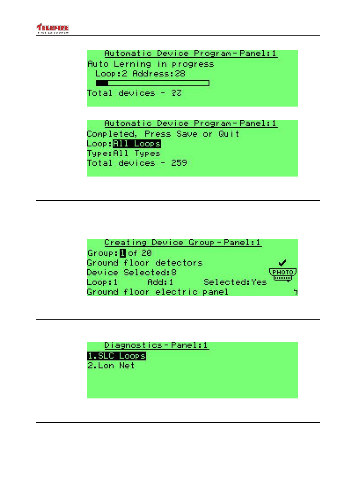
ADR-7000 / SAVER-7000 / GUARD-7
© 2017 – Telefire Fire & Gas Detectors Ltd Revision 0.98 October 2017
Screen 69 Automatic device programming
Screen 70 Automatic device programming – completion message
8.11 Creating Device Groups
Device groups are intended to assign the same entity to several devices without
restrictions of loop, address, or zone in order to perform a single operation such as
disablement in one step. It is possible to assign up to 20 groups.
The second line allows you to assign a name to the group.
Screen 71 Creating groups
8.12 Diagnostics
This option allows you to check validity of device programming or communication
between various control panels.
Screen 72 Diagnostics
8.13 Clear Reports
System reports indicate the total number of alarms, faults, walk tests, and key operations
(silencing, disablement, enablements and resets). Press Enter to clear. Respond with
an asterisk (*) to confirm or hash sign (#) to cancel.
– Page 64 of 87 –
Page 71
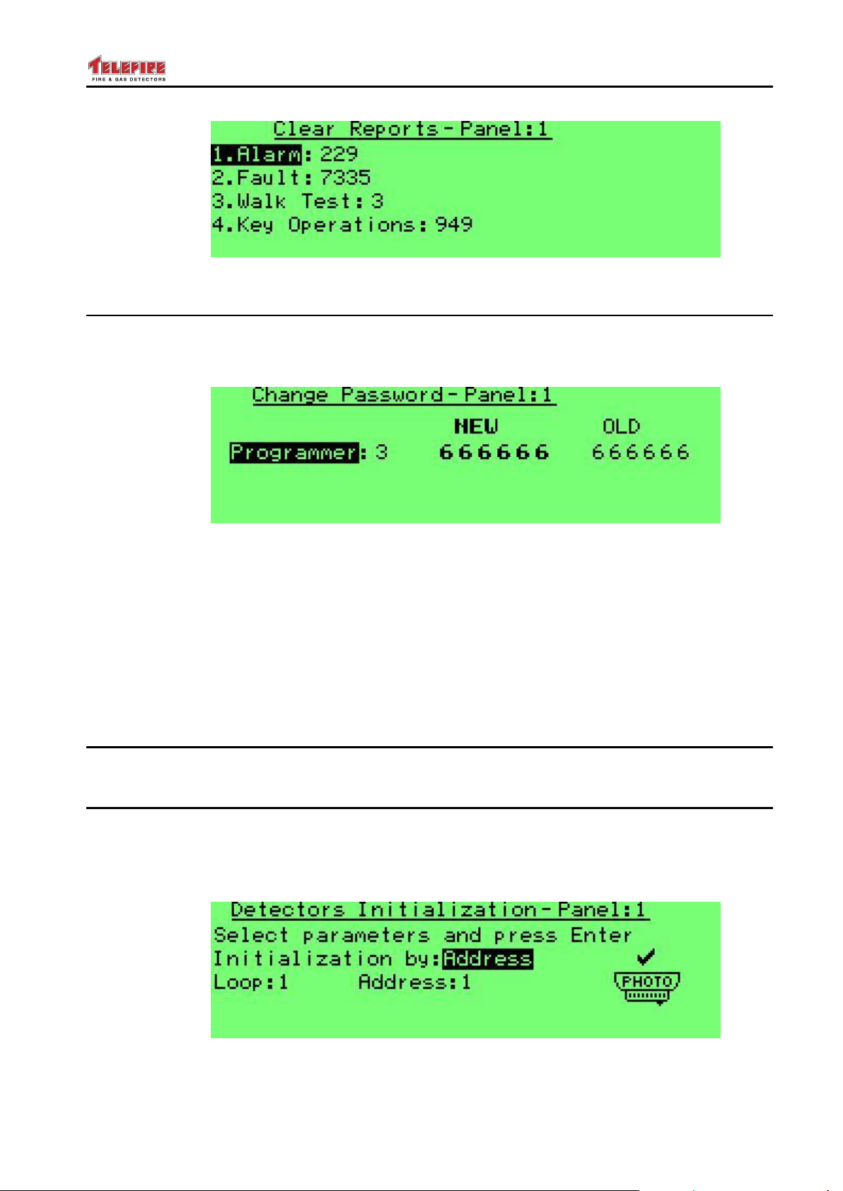
ADR-7000 / SAVER-7000 / GUARD-7
© 2017 – Telefire Fire & Gas Detectors Ltd Revision 0.98 October 2017
Screen 73 Clear reports
8.14 Change Passwords
This menu option allows you to change passwords. There are three IDs for Operator
(EN 54 access level 2) passwords, and three IDs of Programmer (EN 54 access level 3)
passwords.
Screen 74 System Program – Change password
Default passwords are:
Operator 1: 111111
Operator 2: 222222
Operator 3: 333333
Operator 4: 444444
Operator 5: 555555
Operator 6: 666666
8.15 Advanced
Not for field use.
8.16 Detector Initialization
This menu option allows you to force the control panel to perform detector initialization.
It is highly recommended to perform the initialization process when the system is turned
on for the first time, or after installing or changing a detector, as it may take several days
under normal operation.
Screen 75 Detector initialization
– Page 65 of 87 –
Page 72

ADR-7000 / SAVER-7000 / GUARD-7
i
Note
Ensure that detector initialization is performed when all detectors are in a
smoke-free condition.
© 2017 – Telefire Fire & Gas Detectors Ltd Revision 0.98 October 2017
Pressing Enter will activate the fast Initializing. The system will display the message
"DONE!" upon completion. Pressing the Quit key exits this window without performing
the fast update.
– Page 66 of 87 –
Page 73
ADR-7000 / SAVER-7000 / GUARD-7
i
Note
The pound sign (#) in the messages listed in the table of error notices
represents a number that indicates the panel's number, loop card number, or
device address.
Error Messages
Possible Cause
Repair Action
Main Memory is defective
Control panel fault- send the
device to the manufacturer
for repair
Unavailable at this time
Password has been entered
incorrectly 5 times
Wait for half an hour
© 2017 – Telefire Fire & Gas Detectors Ltd Revision 0.98 October 2017
9 Troubleshooting
9.1 LEDs
9.1.1 LEDs on the User Display
See section 6.2 on page 34 for an explanation of LEDs.
9.1.2 LEDs on the Main Board
The red LED light next to the battery connector on the main card turns on when the
charger charges the batteries.
The addressable device communication circuit line (SLC) is electronically protected
against short circuits. The circuit will break the loop if there is a short circuit and it will
return to normal operations automatically upon removal of the short circuit. Each circuit
line includes two LED indicator lights that allow maintenance to distinguish between the
following situations:
Flashing red light (LED 3) indicates that it is addressing an addressable device
Solid yellow light (LED 4) indicates a communication fault, including in the event of a
momentary fault that does not activate a system wide fault mode
9.1.3 LEDs on the Loop Card
The LEDs at the line cards have electronic protection form shorts. The circuitry shall
disconnect the loop if it senses a short and will resume normal operation when the fault
is rectified. Every line card has two LEDs to indicate the following conditions:
A red LED (LED 1) flickers upon every communication with addressable device.
A yellow LED (LED 2) is on whenever there is a communication error, even for a
temporary error
9.2 Control Panel Error Messages
9.3 System Faults
– Page 67 of 87 –
Page 74

ADR-7000 / SAVER-7000 / GUARD-7
Error Messages
Possible Cause
Repair Action
Main circuit <device> "-"
There is a negative line to
earth fault on the indicated
device (NAC1; 24V-A output
circuit; dial-up alarm; dialer
FWRE )dial up connection
failure); batteries' charger; a
loop; or the annunciator
panel
Find the source of the fault
–damaged wire or a water
leak – and fix it.
Main circuit <device> "+"
There is a positive line to
earth fault line on the
designated device (NAC1;
24V-A output circuit; dial-up
alarm; dialer FWRE (dial up
failure); battery charger; or
loop
Find the source of the fault
–damaged wire or a water
leak – and fix it.
Main circuit <device>
limited current
The current has been limited
on the designated device
(AC1N; 24V-A output circuit;
dial-up alarm; dialer FWRE
dial up connection failure);
battery charger; or a loop
Find the source of the fault
–damaged wire or a water
leak – and fix it.
Main circuit <device> low
voltage
The voltage is low on the
designated device (AC1N;
24V-A output circuit; dial-up
alarm; dialer FWRE )dial up
connection failure); battery
charger; circuit loop; 3V
battery backup or batteries
If the device is the battery or
backup battery (3V): replace
the battery or backup
battery (R2032C).
Control panel fault – send to
the manufacturer for repairs
Main circuit <device>
disconnect
The designated device is
disconnected (NAC1; 24V-A
output circuit; dial-up alarm;
dialer FWRE )dial up
connection failure)
Check line continuity and
connect an end of line
resistor (5.1KΩ) at the
output circuit connectors.
Main circuit <device> short
There is a short circuit on
the designated device
(NAC1; 24V-A output circuit;
dial-up alarm; dialer FWRE
)dial up connection failure)
battery charger; or loop
Find the cause of the short
circuit and remove it
Main circuit <device>
exists, not programmed
The designated device (the
annunciator panel; detector;
button; or an input or output
module) is present in the
system, but it has not been
defined as yet.
Define the device
© 2017 – Telefire Fire & Gas Detectors Ltd Revision 0.98 October 2017
– Page 68 of 87 –
Page 75
ADR-7000 / SAVER-7000 / GUARD-7
Error Messages
Possible Cause
Repair Action
<address> "-"
There is a negative line to
earth fault at the indicated
address
Find the source of the fault –
damaged wiring or water
leak – and fix it
<address> "+"
There is a positive line to
earth fault at the indicated
address
Find the source the fault –
damaged wiring or water
leak – fix it
<address> limited
current
A short circuit at the
designated address
associated with an input or
output circuit
Find the cause of the short
circuit, remove the problem
and replace the fuse
<address> loop with
short
Find the source of the fault –
damaged wire or a water leak
– and fix it.
<address> low 24V
voltage
Low or missing voltage; an
card's input circuit voltage
fault
Check the input voltage and
its supply sources
<address> low voltage
Find the source of the fault –
damaged wire or a water leak
– and fix it.
<address> Blown fuse
A blown fuse in a 24V device
Find the cause of the short
circuit, remove it, and replace
the fuse
<address> disconnect
An input/output circuit in a
device is disconnected
Check the line for
breaks/damage and connect
a resistor at the end of the
line on the input/output
connectors
<address> code not
valid
Illegal Opcode
Replace the device indicated
in the message
<address> short
A short circuit in an
input/output device
Find the cause of the short
circuit and remove it
<address> wrong
answer
Trouble address
Trouble address place
Trouble opcode place
Trouble opcode
Replace the device indicated
in the message
<address> extinguishing
circuit is disconnected
The extinguishing circuit is
disconnected at the
extinguishing controller
<address> short in
extinguishing circuit
A short circuit in an
extinguishing circuit at the
extinguishing controller
© 2017 – Telefire Fire & Gas Detectors Ltd Revision 0.98 October 2017
9.4 Addressable Device Faults
– Page 69 of 87 –
Page 76
ADR-7000 / SAVER-7000 / GUARD-7
Error Messages
Possible Cause
Repair Action
<address> sirens circuit
is disconnected
The siren circuit is
disconnected at the
extinguishing controller
Reconnect
<address> output
evacuation circuit is
disconnected
The output evacuation circuit
is disconnected at the
extinguishing controller
Reconnect
<address> a short in the
output evacuation circuit
A short circuit in an output
evacuation circuit at the
extinguishing controller
Reconnect
<address> disconnect
on manual override
Manual override is
disconnected at the
extinguishing controller
Reconnect
<address> Short on
manual override
Short circuit on Manual
override at the extinguishing
controller
Reconnect
<address> pressure
switch is disconnected
Pressure switch is
disconnected at the
extinguishing controller
Reconnect
<address> short circuit
on the pressure switch
Short circuit on pressure
switch at the extinguishing
controller
Reconnect
<address> abort
extinguishing is
disconnected
Abort extinguishing is
disconnected at the
extinguishing controller
Reconnect
<address> short circuit
on abort extinguishing
Short circuit on abort
extinguishing at the
extinguishing controller
Reconnect
<address> empty
extinguishing container
Empty extinguishing
container is disconnected at
the extinguishing controller
Reconnect
<address> extinguishing
circuit is disconnected
The extinguishing circuit is
disconnected at the
extinguishing controller
Reconnect
<address> short in
extinguishing circuit
A short circuit in an
extinguishing circuit at the
extinguishing controller
Resolve
<address> sirens circuit
is disconnected
The siren circuit is
disconnected at the
extinguishing controller
Reconnect
<address> output
evacuation circuit is
disconnected
The output evacuation circuit
is disconnected at the
extinguishing controller
Reconnect
© 2017 – Telefire Fire & Gas Detectors Ltd Revision 0.98 October 2017
– Page 70 of 87 –
Page 77
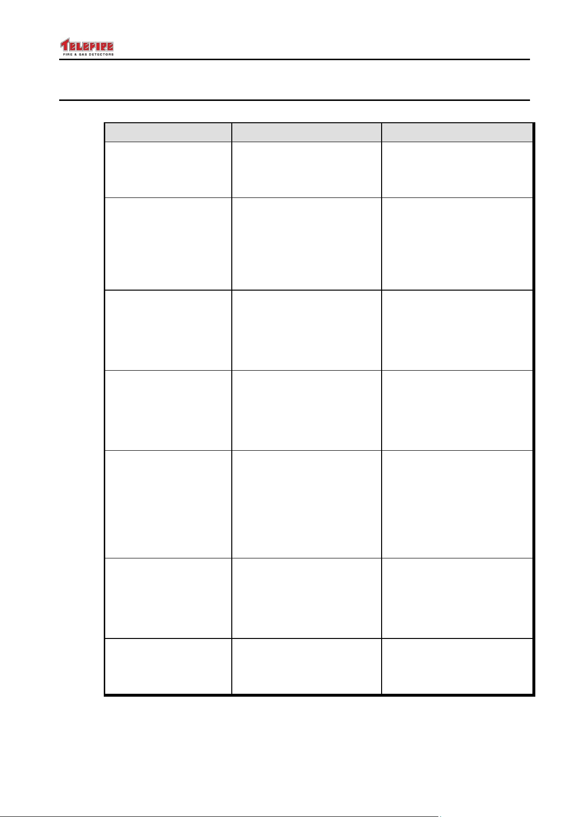
ADR-7000 / SAVER-7000 / GUARD-7
Error Messages
Possible Cause
Repair Action
<address> exists, not
programmed
There is a device attached to
the addressable circuit that
was not programmed
Program the device in, open
system programming,
programming devices, and
add the device.
<address> same
address
There are two devices with
the same address
Run diagnostics. The control
panel will turn on a red
indicator light on all the
devices with the same
address. Change
the address for one of the
devices using PROG 4000.
Device Matrix: the
number of devices is
lower than the number
of alarms
Alarm conditions cannot be
met because the requirement
is that there have to be more
alarms than the number of
devices defined within the
matrix
Reduce the number of input
devices required activate the
output or add input devices to
the operation matrix
Input device listed in
matrix has been
cancelled
This message will be
received when the one of the
system's input devices is
removed, but the device still
belongs to the activation
matrix of the output device
Disabled
A device or area is disabled
If you want to turn on the
device:
Open start/stop device menu
from the main menu, select
the device or the
area indicated in
the message, and click
Enable.
Supervisory output
circuit without a
supervisory switch in a
selected area
An output circuit has been
defined as a Supervisory
output circuit, but a
supervisory switch has not
been defined in the same
area
Define a supervisory switch in
the same area as a
supervisory output circuit
define the switch as an
ordinary switch (siren,
light, etc.)
The extinguishing output
circuit cannot be
programmed as a
general output circuit
A mistake in the
extinguishing output circuit
definitions
Define the operating
conditions as a matrix
© 2017 – Telefire Fire & Gas Detectors Ltd Revision 0.98 October 2017
9.5 Programming Faults
– Page 71 of 87 –
Page 78

ADR-7000 / SAVER-7000 / GUARD-7
Error Messages
Possible Cause
Repair Action
The area matrix includes
a region that was
removed from the
programming
This message will be
received when a region's
definitions are changed in an
input device or when an input
device is cancelled in a way
that causes a region that was
previously defined for
activation of an output device
is no longer active.
Reactivate the disabled
detectors or remove the
missing from output device's
list of areas
The device matrix
includes a device which
has been removed from
programming
Restore the device to the
programming matrix or
change the matrix settings
The number of sirens
cannot be greater than
the number of
the selected alarm areas
An alert that the number of
areas enabled to activate an
output device is larger than
the total number of areas in
the matrix
Reduce the number of areas
under alarm necessary to
activate the output device or
add areas so that their
number will be higher than
the necessary minimum for
activation
The number of sirens
cannot be greater than
the number of devices in
the selected areas
An alert that the selected
number of alerts required to
activate an output device is
greater than the total number
of input devices in the
selected under the matrix
Reduce the number of input
devices required to activate
the output device or add
devices in the area so that
the number is larger than the
necessary minimum for
activation
The number of alarms
cannot be greater than
the number of alarm
devices in the area: #
An alert that the selected
number of alarms necessary
in one area to activate an
output device is larger than
the total number of input
devices in one of the areas
selected to activate the
device matrix
Reduce the number of input
devices required to activate
an output device or
add devices the area where
the number of devices is too
low under the activation
matrix
The number of alarms
cannot be greater than
the number of selected
alarm devices
Activate the device or
remove the device from the
output device operational
matrix
The wrong device type
The type of device in the field
does not match the
programmed definition
A locked control panel with
unlocked detectors or an
unlocked control panel with
locked detectors
Correct the device definitions
(programming) or adjust the
type of device to match the
instructions
Replace the control panel or
the detectors
© 2017 – Telefire Fire & Gas Detectors Ltd Revision 0.98 October 2017
– Page 72 of 87 –
Page 79

ADR-7000 / SAVER-7000 / GUARD-7
Error Messages
Possible Cause
Repair Action
Panel #
communication
error
A control panel that is defined
as Partner is disconnected or
powered off
Ensure that the control panel
is on and verify connection
© 2017 – Telefire Fire & Gas Detectors Ltd Revision 0.98 October 2017
9.6 Status Messages
These messages show a system status such as a phone call on a fireman phone system
or Extinguishing Abort or Extinguishing Hold in progrees. Information only – no need for
any action.
9.7 Control Panel Network Faults
– Page 73 of 87 –
Page 80

ADR-7000 / SAVER-7000 / GUARD-7
© 2017 – Telefire Fire & Gas Detectors Ltd Revision 0.98 October 2017
10 Periodic Tests
Periodic maintenance shall be, as a minimum, performed per NFPA 72. Maintenance
shall be performed by a trained or authorized Telefire representative.
The system should be inspected entirely at least twice a year, or as required by national
and/or local fire codes. All devices, system wiring and component functions should be
tested and maintained. These inspections should be performed in addition to the routine
maintenance activities such as cleaning the detectors (which should be performed in
accordance with Telefire's instructions).
Maintenance and test actions shall be conducted by a company or service technician
authorized by Telefire.
Records of all inspection and maintenance activities should be kept.
10.1 Weekly Test – Done by Site Supervisor
The site's safety supervisor should inspect the control panel weekly and verify that all of
the following conditions exist:
The green LED is on and is not blinking
None of the yellow or red LEDs are on or blinking
The control panel's trouble buzzer does not sound
The LCD display states SYSTEM OK and the correct time
Open the control panel's front door and verify that the red LEDs on the line card flash
occasionally.
Call your service company if any of these conditions is not met.
10.2 Battery Test
The battery supervising and charging circuitry includes a battery supervision and battery
test that are managed by the control panels' microprocessor. This includes
disconnection, charging current, battery voltage, and the batteries' ability to supply the
required current under load. If any of the parameters is outside the required parameters
will cause a detailed fault indication.
Replace the battery if you encounter an error indicating inability to supply sufficient
current.
Ensure that the battery connectors are clean and free of corrosion and that there is a
proper (mechanically secure) connection. Tighten as needed.
– Page 74 of 87 –
Page 81

ADR-7000 / SAVER-7000 / GUARD-7
i
Note
Fire alarm systems are composed and assembled of different devices and
subsystems, such as control panels, annunciators, smoke detectors, heat
detectors, manual call points, extinguishing activation devices, and
annunciating devices intended to alert to fire / smoke.
Using this system does not ensure protection from or prevention of fire and/or
smoke damages, but proper use of the system may reduce fire and smoke
damages.
Proper system configuration design, including all of its components
and infrastructure, as well as proper installation according to the
manufacturers' instructions and the applicable standards – are a
conditioned precedent for the proper and efficient function of the
system.
The designer and installer should have the appropriate skills and
qualifications for performing said installation and all damages or losses
resulting from improper design and/or installation lie with the designer and/or
installer alone.
All loss or damage caused by improper action shall lie with the
originator of said improper action.
The manufacturer shall not be liable for any fire and/or fire damages caused
by fire in location where fire systems are installed and or results of direct or
indirect fire damage that may be caused to any persons and/or property
and/or third parties as a result of using the ADR-7000 and/or resulting from its
inaction.
i
Note
Do not install, operate, or maintain this ADR-7000 before fully reading this
manual.
© 2017 – Telefire Fire & Gas Detectors Ltd Revision 0.98 October 2017
11 Warnings and Limitations
– Page 75 of 87 –
Page 82

ADR-7000 / SAVER-7000 / GUARD-7
© 2017 – Telefire Fire & Gas Detectors Ltd Revision 0.98 October 2017
12 Compatibility
The ADR-7000 control panel is compatible with all of the following devices:
12.1 Input Devices
12.1.1 Direct Attachment to the SLC Loop
ADR-7xx Addressable Multi Input Module
ADR-805A Addressable Flow Switch Interface Module
ADR-812A Addressable Two-Channel Input Module
ADR-818A Addressable Eight-Channel Input Module
TFH-280A Addressable Heat Detector
TFO-480A Addressable Photo-Electric Smoke Detector
TPH-482A Addressable Photo/Heat Detector
12.1.2 Connection via an Input Module
TPH-482 and TPH-442 conventional smoke/heat detectors
TFO-480 and TFH-440 conventional smoke detectors
TFH-280F, TFH-281F, TFH-281R, TFH-282F, TFH-282R, TFH-283F, TFH-283R
and TFH-220F conventional heat detectors
TPB-10R, TPB-10Y and TPB-10B conventional call points
TXB-435 barrier
12.1.3 Connection via a TRA-1 Adaptor and an Input Module
TBD-50, TBD-100, TBD-40, and TBD-8100 beam detectors
LASD-1 and LASD-2 aspirating detectors
Sensitron Smart 3 gas detectors
OSID –TRALIS camera detector
12.2 Output Modules
12.2.1 Direct Attachment to the SLC Loop
ADR-723 Addressable High power output module
ADR-741 Addressable relay module
ADR-742 Addressable speaker switching
ADR-823A Addressable Three-Channel I/O Module
ADR-828A Addressable Eight-Channel Output Module
TIP-224A Addressable Indoor Alarm Notification Sounder
TFP-3000 fireman phone
12.2.2 Connection via an Output Module or Directly to NACs
TIP-224 and TIP-114 sounders
TFS-214S and TFS-214 sounder / strobes
TFS-4406a and TFS-4460– waterproof sounders
TFS-4484 – waterproof sounder strobe
TES-553 – extinguishing activated signs
– Page 76 of 87 –
Page 83

ADR-7000 / SAVER-7000 / GUARD-7
UL
UL Certification
Please note that the ADR-7000 was certified to UL 864 with the following
devices:
TFO-480A and TFO-440A Photoelectric Smoke Detectors
ADR-705 and ADR-805A Addressable Switch Input
ADR-712 and ADR-718 Input Modules
ADR-723 and ADR-823A Output Modules
LI-3000, LI-3000C, and LI-3000E sort circuit isolators
TPS-73A Addressable Auxiliary Power Supply
© 2017 – Telefire Fire & Gas Detectors Ltd Revision 0.98 October 2017
TES-553B – extinguishing activated signs / sounders
TDH-315 and TDH-369 – door magnets
12.2.3 Extinguishing devices
SAFE (older series) gas cylinders via TLA-110 adaptor
SAFE (TFN series) gas cylinders via TLA-115 adaptor
Fike FIRERASER gas cylinders via TLA-130 adaptor
Fike GCA gas cylinders via TLA-22 adaptor
Fike Impulse gas cylinders via TLA-23 adaptor
Firepro aerosol generators via TLA-44 adaptor
Greenex aerosol generators via TLA-33 adaptor
12.2.4 Other devices
LI-3000, LI-3000C, and LI-3000E short circuit isolators
TPS-74A and TPS-34A auxiliary power supplies
12.3 UL Listing
– Page 77 of 87 –
Page 84

ADR-7000 / SAVER-7000 / GUARD-7
© 2017 – Telefire Fire & Gas Detectors Ltd Revision 0.98 October 2017
13 Specification
13.1 General Specification
Dimensions (W / H / D) ................................................. 140 / 332 / 505 mm
Operating Temperature range ....................................... -10°C – +60°C (14°F – 140°F)
Operating Voltage ......................................................... 230 Vac
Mains AC Current Consumption
basic configuration (1 loop) ................................ .... 60.0mA
each additional loop card ....................................... 17.0mA
LON-7000 .............................................................. 10.0mA
NET-7000 .............................................................. 120.0mA
Mains AC Current Consumption – 2 devices in alarm (control panel only)
basic configuration (1 loop) ................................ .... 280.0mA
each additional loop card ....................................... 17.0mA
LON-7000 .............................................................. 10.0mA
NET-7000 .............................................................. 120.0mA
Ground fault resistance
low sensitivity ......................................................... 14kΩ - 30KΩ
medium sensitivity .................................................. 30K Ω - 60KΩ
high sensitivity ....................................................... 50KΩ - 90KΩ
Event log
9,999 alarms / 9,999 faults
Drift compensation update time .................................... 3 hours
13.2 Power Supply
The ADR-7000 contains a 150W power supply. The SAVER-7000 and GUARD-7
contain a 100W power supply.
Battery charging ............................................................ automatic, variable current
automatically controlled. Max charging current 1,500mA ±10%
Batteries
two sealed lead-acid batteries, total voltage 24Vdc (two 12V batteries in series) with
a max capacity of 18AH (ADR-7000) or 12AH (SAVER-7000 or GUARD-7)
Battery capacity shall be determined according to the authority having jurisdiction.
13.3 Remote Anunciators
Remote annunciators
ADR-7000 .............................................................. up to 16 RM-7000 annunciators
SAVER-7000 / GUARD-7 ....................................... up to 3 RM-7000 annunciators
13.4 Main Board – Field Connection
NAC 1
Activation mode ..................................................... Reversed polarity, silenceable
NFPA classification ................................ ................ NFPA 72 Style Y
Activation condition ................................................ any alarm, silenceable
Current protection .................................................. electronic current limit
Max Current: .......................................................... 1.0A 24Vdc
EOL Resistor ......................................................... 5.1 KΩ
– Page 78 of 87 –
Page 85

ADR-7000 / SAVER-7000 / GUARD-7
5
© 2017 – Telefire Fire & Gas Detectors Ltd Revision 0.98 October 2017
NAC 2 – See NAC 1
unavailable for SAVER-7000
SLC card 1
NFPA classification: Class B (NFPA style 4) or Class A (NFPA style 6 or 7)
Class B or Class A is configurable at single loop level
current protection ................................................... electronic
max loop current .................................................... 400mA
Nominal loop voltage ............................................. 21V, modulated
Maximum loop impedance ..................................... 40Ω
Maximum loop capacitance .................................... 1.0 µF
left connector (marked SLC ) is used for outgoing (Class B or Class A)
right connector (marked as SLC ) is used for return (Class A only)
24V_A auxiliary output
Activation condition ................................................ always on
Current protection .................................................. electronic current limit
Max Current: .......................................................... 2.0A 24Vdc
SLC card 2 – see SLC card 1
24 V_A Dialer
mode ...................................................................... constant voltage supply
current protection ................................................... electronic
max current ............................................................ 0.3A @ 24Vdc
Dialer activation
mode ...................................................................... level activation
max current AL output ............................................ 70mA @ 24Vdc
max current TR output ........................................... 70mA @ 24Vdc
SLC card 3 – see SLC card 1
inactive in SAVER-7000
24V_B1 auxiliary output5
Activation condition ................................................ always on
Current protection .................................................. electronic current limit
Max Current: .......................................................... 2.0A 24Vdc
SLC card 4 – see SLC card 1
inactive in SAVER-7000
24V_B2 auxiliary output5
Activation condition ................................................ always on
Current protection .................................................. electronic current limit
Max Current: .......................................................... 2.0A 24Vdc
13.5 Main Board – Relays
Relays........................................................................... 3, unsupervised
Relay activation ..................................................... programmable, silenceable
Max rating .............................................................. 1.5A 48Vdc
Relay contacts are unsupervised and are intended for same room connection
only.
All values are nominal. Specifications are subject to change without prior notice
Combined 24V_B1 and 24V_B2 output current shall not exceed 2.0A
– Page 79 of 87 –
Page 86

ADR-7000 / SAVER-7000 / GUARD-7
© 2017 – Telefire Fire & Gas Detectors Ltd Revision 0.98 October 2017
14 Certification
Telefire’s ADR-7000 Addressable Control Panels have the following approvals:
EN 54 Approved
UL 864 Edition 10 Listed
GOST Approved
CP 10 Compliant
IS 1220 Approved
CE Marked
– Page 80 of 87 –
Page 87
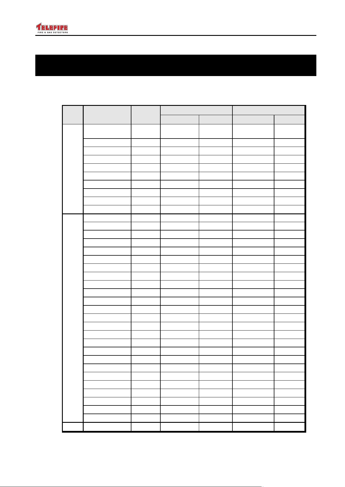
ADR-7000 / SAVER-7000 / GUARD-7
Quiescence
Alarm
Device
QTY
Current
Total
Current
Total
Internal modules and
NACs
ADR-7000/1
(single loop)
{ } X
76.00 mA
=
280.0 mA
=
Additional loops
{ } X
17.00 mA
=
17.0 mA
=
LON-7000
{ } X
10.00 mA
=
10.0 mA
=
NET-7000
{ } X
120.00 mA
=
120.0 mA
=
GIM-232
{ } X
1.50 mA
=
1.5 mA
=
TDM-500i
{ } X
20.00 mA
=
300.0 mA
=
TIP-224
{ } X
0 mA
= 0
40.0 mA
=
Other NAC
{ } X
mA
=
mA
=
Other NAC
{ } X
mA
=
mA
=
Other NAC
{ } X
mA
=
mA
=
Current to loops
TFO-480A / 440A
{ } X
0.29 mA
=
2.6 mA
=
TFH-280A / 220A
{ } X
0.20 mA
=
2.6 mA
=
TPH-482A / 442A
{ } X
0.29 mA
=
2.6 mA
=
TFL-1AN
{ } X
0 mA
= 0
10.0 mA
=
TPB-800ASR
{ } X
0.12 mA
=
2.0 mA
=
TPB-800ASY
{ } X
0.12 mA
=
2.0 mA
=
LI-3000C
{ } X
2.20 mA
=
4.0 mA
=
LI-3000E
{ } X
0.5 mA
=
4.0 mA
=
ADR-712
{ } X
0.3 mA
=
15.0 mA
=
ADR-718
{ } X
0.3 mA
=
15.0 mA
=
ADR-723
{ } X
0.2 mA
=
2.8 mA
=
ADR-741
{ } X
0.3 mA
=
3.2 mA
=
ADR-805A Rev B
{ } X
0.26 mA
=
3.0 mA
=
ADR-805A Rev C
{ } X
0.20 mA
=
2.0 mA
=
ADR-812A
{ } X
0.15 mA
=
2.1 mA
=
ADR-818A
{ } X
0.26 mA
=
2.1 mA
=
ADR-823A
{ } X
0.30 mA
=
2.8 mA
=
ADR-828A
{ } X
0.39 mA
=
3.0 mA
=
ADR-833A
{ } X
6.50 mA
=
6.5 mA
=
TIP-224A
{ } X
0.12 mA
=
5.0 mA
=
TPS-34A
{ } X
0.34 mA
=
0.5 mA
=
TFP-3000
{ } X
15.00 mA
=
70.0 mA
=
TFP-1CP
{ } X
0.25 mA
=
2.8 mA
=
TFP-806
{ } X
0.25 mA
=
2.8 mA
=
TFP-828
{ } X
0.39 mA
=
3.0 mA
=
Totals (a)
=
(b)
=
© 2017 – Telefire Fire & Gas Detectors Ltd Revision 0.98 October 2017
Appendix A – Current Consumption and Battery Capacity
Calculation
Repeat this process separately for each control panel.
Fill in the following table to calculate the total load on the system’s power supply during
quiescence (standby) state and alarm.
– Page 81 of 87 –
Table 3 Power Requirement – Internal and SLC
Page 88
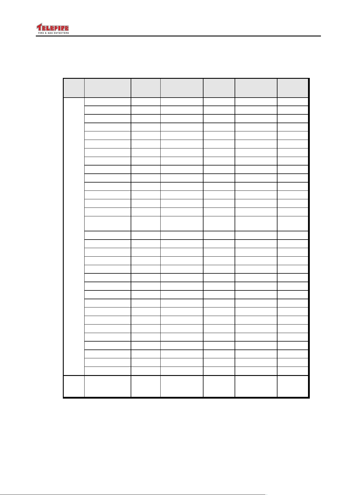
ADR-7000 / SAVER-7000 / GUARD-7
Quiescence
Alarm
Device
QTY
Current
Total
Current
Total
SLC connected modules and devices
ADR-712
{ } X
50 mA
=
mA
=
ADR-718
{ } X
50 mA
=
mA
=
ADR-723
{ } X
0.9 mA
=
mA
=
ADR-812A
{ } X
11.5 mA
=
80.0 mA
=
ADR-818A
{ } X
40.0 mA
=
100.0 mA
=
ADR-823A
{ } X
4.0 mA
=
32.0 mA
=
ADR-828A
{ } X
10.0 mA
=
125.0 mA
=
ADR-833A
{ } X
20.0 mA
=
120.0 mA
=
TIP-224A
{ } X
0.1 mA
=
45.0 mA
=
RM-4005
{ } X
40.0 mA
=
70.0 mA
=
TLA-22
{ } X
2.0 mA
=
0.0 mA
=
TLA-23
{ } X
2.0 mA
=
0.0 mA
=
TLA-33
{ } X
3.0 mA
=
0.0 mA
=
TLA-42
{ } X
2.0 mA
=
0.0 mA
=
TLA-44/1 or
TLA-44
{ } X
5.0 mA
=
0.0 mA
=
TLA-110
{ } X
1.5 mA
=
0.0 mA
=
TLA-120
{ } X
1.5 mA
=
0.0 mA
=
TLA-130
{ } X
1.5 mA
=
0.0 mA
=
TLA-140
{ } X
1.5 mA
=
0.0 mA
=
TLA-150
{ } X
1.5 mA
=
0.0 mA
=
TLA-160
{ } X
1.5 mA
=
0.0 mA
=
TLA-165
{ } X
1.5 mA
=
0.0 mA
=
TLA-170
{ } X
1.5 mA
=
0.0 mA
=
TLA-180
{ } X
1.5 mA
=
0.0 mA
=
TLA-190
{ } X
1.5 mA
=
0.0 mA
=
TFP-3000
{ } X
34.0 mA
=
80.0 mA
=
TFP-1CP
{ } X
0.0 mA
=
2.0 mA
=
TFP-806
{ } X
0.0 mA
=
2.0 mA
=
TFP-828
{ } X
10.0 mA
=
125.0 mA
=
Other NAC
{ } X
mA
=
mA
=
Other NAC
{ } X
mA
=
mA
=
Other NAC
{ } X
mA
=
mA
=
Total 24Vdc
current
consumption
(c) (d)
© 2017 – Telefire Fire & Gas Detectors Ltd Revision 0.98 October 2017
At least one and no more than two line cards (ADR-3002 and ADR-3002C) of any
combination can be installed in the ADR-7000.
Only one module (NET-7000 or GIM-232) can be installed in the lower expansion slot.
– Page 82 of 87 –
Table 4 Power Requirement – 24Vdc
First fill in the quantities of devices attached to the system in Table 3 and calculate total
current load of the internal configuration and load on the SLC loop.
Secondly calculate the power draw from the system’s 24V output (Table 4).
Page 89
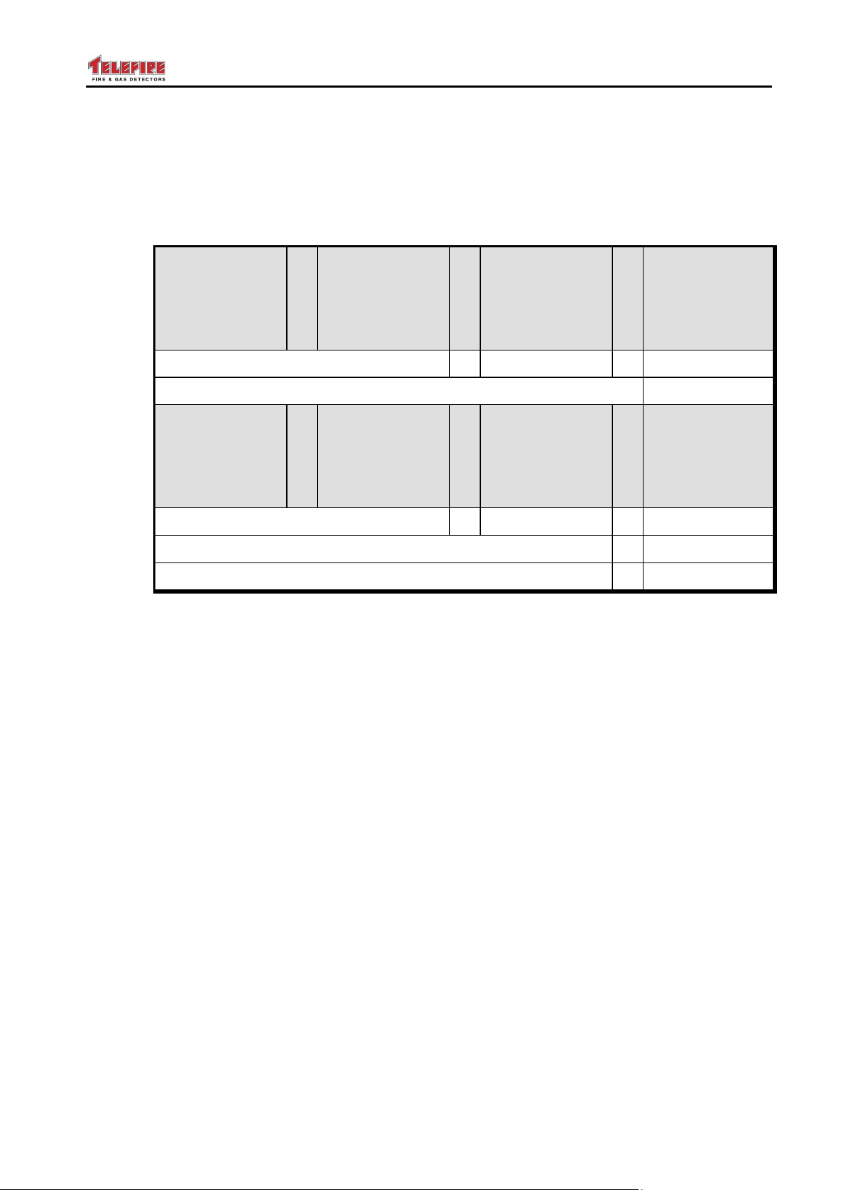
ADR-7000 / SAVER-7000 / GUARD-7
Standby Mode
Current from
Control Panel
(A)
(a)
+
Standby Mode
Current from
the 24Vdc
source (A)
(c)
X
24 Hours
60 Hours
4 Hours
=
Standby Mode
Amp Hr.
({ } + { })
X
{ } =
+
Alarm Mode
Current from
Control Panel
(A)
(b)
+
Alarm Mode
Current from
the 24Vdc
source (A)
(d)
X
5 Minutes
(0.084H)
=
Alarm Mode
Amp Hr.
({ } + { })
X
{ } =
Ampere Hours Sum
=
Ampere Hours Sum X 1.2 derating factor
=
© 2017 – Telefire Fire & Gas Detectors Ltd Revision 0.98 October 2017
Thirdly copy the appropriate fields into Table 5 and calculate battery requirement and
system load.
Multiply the number of devices of each type with the current and calculate the total
current.
When connecting indicating output devices such as horns and bells to output modules,
add their current to the total current for both standby mode and alarm mode.
Table 5 Power Requirement – Final Calculation
The ADR-7000’s power supply module can charge batteries in capacity of up to 12AH.
The battery enclosure can contain two 12V sealed lead-acid batteries, up to 20 (W) by
7 (D) by 12 (H) cm each.
For fire alarm control panels requiring larger batteries use the BC-3000 external battery
enclosure. This enclosure can contain two 12V sealed lead-acid batteries, up to 20 (W)
by 10 (D) by 15 (H) cm each.
If the system requires larger battery capacity than 12 AH add the TPS-34A Auxiliary
Power Supply with its own batteries. Please refer to the TPS-34A manual for additional
details about the TPS-34A auxiliary power supply.
Additional TPS-34A power supplies are required if one or more of the following
conditions is true:
The quiescence 24V current draw exceeds the control panel's power supply
limitations (0.5A for ADR-4004TSW)
The 24V current draw in alarm exceeds the control panel's power supply limitations
(4.0A for ADR-4004TSW)
There is a need for batteries in capacity that exceeds the control panel's power
supply limitations (12AH for ADR-4004TSW)
The voltage drop on the 24V lines exceeds allowed limitation (no more than 2V at
the furthest device, while still leaving sufficient voltage for the device to operate).
– Page 83 of 87 –
Page 90

ADR-7000 / SAVER-7000 / GUARD-7
i
Note
TPS-34A Addressable Auxiliary Power Supplies should be installed as close
as possible to the devices they provide power to in order to reduce power
loss.
TPS-34A auxiliary power supplies should not be shared between multiple
control panels or between line cards on the same control panel. TPS-34A
auxiliary power supplies may be shared between the two loops of a single
ADR-3002C line card.
© 2017 – Telefire Fire & Gas Detectors Ltd Revision 0.98 October 2017
When are Auxiliary Power Supplies Needed?
Large fire detection and alarm systems that require high current 24Vdc power may be
expanded by installing TPS-34A auxiliary power supplies. These power supplies may be
used to add 24Vdc power to the system.
Auxiliary power supplies are requires if at least one of the following conditions are met:
Current draw from the 24Vdc outputs is more than 0.5A in quiescence mode or 1.5A
in alarm
The total power consumption of the control panel (the control panel itself and
devices attached and powered by it) is more than 4.0A in alarm
There is a requirement for batteries with more than 12AH capacity
Voltage drop to the last device fed by the 24Vdc output is more than 2V, or does not
allow high enough voltage at the last device to operate it
Auxiliary power supplies should be installed in the field as close as possible to the
devices that they supply 24Vdc to, thereby saving both cabling cost and power losses.
This provides high resilience as the power supplies are distributed and a problem with
one power supply will not affect the rest of the system.
There is no limit to the quantity of power supplies that can be added to the system, up to
hundreds of amperes.
The power supplies are fed from a 230Vac input and include a power supply, battery
charger, and control circuitry. Communication and reporting to the control panel is done
via the SLC, with the power supply occupies a single address.
The power supply can supply up to 4A during alarm. Please see the power supply
manual for further details.
– Page 84 of 87 –
Page 91
ADR-7000 / SAVER-7000 / GUARD-7
Sensitivity
Least
Sensitive
Day
Default
Night
Default
Most
Sensitive
Obscuration
(% per foot)
2.0
1.8
1.6
1.4
1.2
1.0
0.8
Sensitivity
Least Sensitive
Default
Most Sensitive
Fixed Temperature
90°C
50°C
50°C
Rate of Rise
13°C per minute
9°C per minute
7°C per minute
UL
UL Compliance
Please note:
Configure the heat detector as Rate of Rise in the range of 8-13°C per minute
or as Fixed Temperature in the range of 58-70°C to comply with UL 521.
Sensitivity
Least Sensitive
Default
Most Sensitive
Multi-sensor setting
10 5 2
© 2017 – Telefire Fire & Gas Detectors Ltd Revision 0.98 October 2017
Appendix B – Detector Sensitivity Selection
14.1 Smoke Detector Sensitivity Settings
Table 1 Smoke Detector Sensitivity
14.2 Heat Detector Sensitivity Settings
Heat Detectors can be set in two modes:
Fixed temperature – The alarm point can be set between 50°C – 90°C in steps of
1°C.
Rate of rise – The detector will alarm when the rate of temperature rise is equal or
higher than the setting in the Sensitivity Field, in the range of 7°C/minute –
13°C/minute in 1°C/minute steps.
Table 2 Heat Detector Sensitivity
14.3 Multi-Sensor Detectors Sensitivity Setings
A smart algorithm is used by the TPH-482A’s powerful processor to analyze the ambient
temperature, its rate of rise and the trend of these parameters. It then passes a value to
the control panel.
Set the detector’s sensitivity between 2 (most sensitive) and 10 (least sensitive).
Table 3 Multisensor Detector Sensitivity
– Page 85 of 87 –
Page 92
ADR-7000 / SAVER-7000 / GUARD-7
UL
UL 864 Compliance
The ADR-7000 is a UL 864 compliant system that can be used as a standard
fire detection and alarm system including sprinkler supervision; fire detection
and extinguishing release system; fireman phone system; a compliant smoke
control.
Please see section 12.3, UL Listing on page 77 for a list of devices tested for
UL compliance with the ADR-7000.
EN 54
EN 54-2 Compliance
The ADR-7000 complies with all EN 54-2 mandatory functions and the
following options with requirements:
Section 7.8: Output to alarm devices
Section 7.9: Control of fire alarm routing equipment
Section 7.10: Outputs to fire protection equipment
Section 7.11: Delays to outputs
Section 7.12: Dependencies on more than one alarm signal
Section 7.13: Alarm counter
Section 8.3: Fault signals from points
Section 8.4: Total loss of the power supply
Section 8.9: Output to fault warning routing equipment
Section 9.5: Disablement of addressable points
EN 54-4 Compliance
The ADR-7000 complies with EN 54-4 requirements.
Ancillary Functions
The ADR-7000 provides the following additional features:
Auxiliary 24Vdc outputs
View and change user and programmer passwords
Lamp test
View event list
View software and hardware versions
Restore defaults
© 2017 – Telefire Fire & Gas Detectors Ltd Revision 0.98 October 2017
Appendix C – Standards Compliance
14.4 UL 864 Compliance
14.5 EN 54 – Options with Requirements
– Page 86 of 87 –
The ADR-7000 conforms fully to European standards BS EN 54-2:1998 and
BS EN 54-4:1998 and the following optional features:
Output to fire alarm devices – EN 54-2 Section 7.8 option with requirements
Page 93

ADR-7000 / SAVER-7000 / GUARD-7
EN 12094
EN 12094 Compliance
The ADR-7000 complies with EN 12094-1 mandatory functions and the
following options with requirements:
Section 4.17: Delay of extinguishing signal
Section 4.18: Signal representing the flow of extinguishing agent
Section 4.19: Monitoring of the status of components
Section 4.20: Emergency hold device
Section 4.21: Control of flooding time
Section 4.22: Initiating of flooding time
Section 4.23: Manual only mode
Section 4.24: Triggering signals to equipment within the system
Section 4.25: Extinguishing signals to spare cylinders
Section 4.26: Triggering signals to equipment outside the system
Section 4.27: Emergency abort device
Section 4.28: Control of extended discharge
Section 4.29: Release of the extinguishing media for selected flooding zones
Section 4.30: Activation of alarm devices with different signals
CP 10
CP 10 Compliance
The ADR-7000 complies with CP 10:2005 requirements and includes the
following features:
Fire alarm sounder silencing – Clause 2.5.8
Fire alarm buzzer silencing – Clause 2.5.9
Alarm verification feature (AVF) – Clause 2.5.11
© 2017 – Telefire Fire & Gas Detectors Ltd Revision 0.98 October 2017
Output to fire alarm routing equipment – EN 54-2 Section 7.9 option with
requirements
Output to fire protection equipment – EN 54-2 Section 7.10 option with requirements
Alarm Counter – EN 54-2 Section 7.13 option with requirements
Total loss of power supply – EN 54-2 Section 8.4 option with requirements
Output to fault warning routing equipment – EN 54-2 Section 8.9 option with
requirements
Test condition – EN 54-2 Section 10 option with requirements
14.6 EN 12094-1 Compliance
14.7 CP-10
– Page 87 of 87 –
 Loading...