


RX800 Series
Ultra-high Resolution
Video Recording Server
RX806 / RX812 / RX816
User Guide


Table of Contents
Section 1: Introduction...................................................................................................................................7
1.1.Functional Features.........................................................................................................................8
1.2.Package Contents.............................................................................................................................9
1.3.Hardware Feature..........................................................................................................................11
1.Notification LEDs.............................................................................................................................11
2.Main control buttons.........................................................................................................................11
3.Menu control / local playback control buttons.................................................................................12
4.Front USB port.................................................................................................................................12
1.4.Convention Used in This Manual..................................................................................................13
Section 2: Hard Disk Installation, Formatting and Scanning.......................................................................14
2.1.Hard Disk Installation....................................................................................................................14
2.2.Format Hard Disk..........................................................................................................................17
2.3.Hard Scan Hark Disks...................................................................................................................18
Section 3: Setup for Local and Remote Monitoring....................................................................................19
3.1.Setup for Local Monitor................................................................................................................19
3.2.Setup for LAN Connection............................................................................................................20
3.3.Setup for Broadband Internet Connection.....................................................................................24
Section 4: Local Operation..........................................................................................................................27
4.1.Icons Description...........................................................................................................................27
4.2.OSD Menu.....................................................................................................................................28
4.2.1.OSD Menu Operation.................................................................................................................28
4.2.2.OSD Menu Structure..................................................................................................................30
4.3.Basic Operation.............................................................................................................................76
4.3.1.View Live Video.........................................................................................................................76
4.3.2.Recording...................................................................................................................................77
4.3.3.Playback.....................................................................................................................................81
4.3.4.PTZ.............................................................................................................................................82
4.4.Advanced Operation......................................................................................................................85
4.4.1.Install Alarm Sensors and Relay Control Port............................................................................85
4.4.2.Install Tamper Circuit and External Resistors............................................................................86
4.4.3.Event Handling...........................................................................................................................89
4.4.3.1.Arm/Disarm ............................................................................................................................89
4.4.3.2.Security Switch .......................................................................................................................94
4.4.3.3.Alarm ......................................................................................................................................96
4.4.3.4.Motion ..................................................................................................................................103
4.4.3.5.Video Loss ............................................................................................................................106

4.4.3.6.System Tamper .....................................................................................................................107
4.4.3.7.Power Failure ........................................................................................................................108
4.4.3.8.Disk Usage ............................................................................................................................109
4.4.3.9.HDD Fault ............................................................................................................................109
4.4.4.Event Action.............................................................................................................................110
4.4.4.1.Recording...............................................................................................................................110
4.4.4.2.Switch....................................................................................................................................112
4.4.4.3.Dialback.................................................................................................................................113
4.4.4.4.E-mail....................................................................................................................................114
4.4.4.5.SMS.......................................................................................................................................115
4.4.4.6.Buzzer....................................................................................................................................116
4.4.4.7.Event LED.............................................................................................................................117
4.4.4.8.Live Camera..........................................................................................................................117
4.4.4.9.PTZ........................................................................................................................................117
4.4.5.Footage Extraction....................................................................................................................119
4.4.6.Throughput Control..................................................................................................................120
4.4.7.Switch Control..........................................................................................................................121
4.4.8.Time Synchronisation...............................................................................................................122
4.4.9.Import and Export.....................................................................................................................124
4.4.10.User Account..........................................................................................................................125
4.4.11.SMS .......................................................................................................................................129
Section 5: Remote Operation.....................................................................................................................131
5.1.Network Setup.............................................................................................................................131
5.1.1.Port Mapping Setup..................................................................................................................131
5.1.2.sureLINK Setup........................................................................................................................131
5.2.Icons Description.........................................................................................................................132
5.3.Basic Operation...........................................................................................................................134
5.3.1.View Live Video.......................................................................................................................134
5.3.2.Recording.................................................................................................................................136
5.3.3.Playback...................................................................................................................................137
5.4.Advanced Operation....................................................................................................................138
5.4.1.Hard Disk Formatting...............................................................................................................138
5.4.2.Hard Disk Scanning..................................................................................................................138
5.4.3.Hard Disk Turn On/OFF...........................................................................................................138
5.4.4.Event Handling.........................................................................................................................139
5.4.4.1.Arm/Disarm...........................................................................................................................139
5.4.4.2.Security Switch......................................................................................................................140
5.4.4.3.Alarm.....................................................................................................................................141

5.4.4.4.Motion...................................................................................................................................142
5.4.4.5.Video Loss.............................................................................................................................142
5.4.4.6.System Tamper......................................................................................................................142
5.4.4.7.Power Failure.........................................................................................................................142
5.4.4.8.Disk Usage.............................................................................................................................143
5.4.4.9.HDD Fault.............................................................................................................................144
5.4.4.10.System restart......................................................................................................................145
5.4.5.Event Action.............................................................................................................................146
5.4.5.1.Recording..............................................................................................................................146
5.4.5.2.Switch....................................................................................................................................146
5.4.5.3.Dialback.................................................................................................................................146
5.4.5.4.E-mail....................................................................................................................................147
5.4.5.5.SMS.......................................................................................................................................147
5.4.5.6.Buzzer....................................................................................................................................147
5.4.5.7.Event LED.............................................................................................................................147
5.4.5.8.Live Camera..........................................................................................................................148
5.4.5.9.PTZ........................................................................................................................................148
5.4.6.Pan Tilt Zoom (PTZ) ...............................................................................................................148
5.4.7.Footage Extraction....................................................................................................................150
5.4.8.Throughput Control..................................................................................................................151
5.4.9.Time Synchronisation...............................................................................................................151
5.4.10.Import and Export...................................................................................................................151
5.4.11.User Account..........................................................................................................................153
5.4.12.Maintenance Log Backup.......................................................................................................153
Appendix A : Safety Instruction.................................................................................................................154
Appendix B : Limited Warranty.................................................................................................................155
Appendix C : sureLINK Technology.........................................................................................................156
Appendix D : Firmware Upgrade..............................................................................................................162
Appendix E : Security Mode......................................................................................................................163
Appendix F : General Terms Discussion...................................................................................................166
Appendix G : Audit Trail Log Description................................................................................................167
Appendix H : Specifications......................................................................................................................171

Notice:
Signal Communications Limited reserves the right to make improvements to the product described in this manual at
any time and without notice.
This manual is copyrighted. All rights are reserved. This manual should not be copied, reproduced or translated in
whole or part without prior consent from Signal Communications Limited.
TeleEye is a trademark of Signal Communications Limited and is registered in China, European Communities, Hong
Kong, US and other countries.
All other trademarks are the property of their respective owners.
Copyright (c) 2014 Signal Communications Limited (A member of TeleEye Group). All rights reserved.
Version 1.00
Limits of Liability and Disclaimer of Warranty
Signal Communications Limited has taken care in preparation of this manual, but makes no expressed or implied
warranty of any kind and assume no responsibility for errors or omissions. No liability is assumed for incidental or
consequential damages in connection with or arising out of the use of the information or accessories contained
herein.
Features and specifications are subject to change without prior notice.

Section 1: Introduction
TeleEye RX800 Series is a range of 6-, 12- and 16-channel ultra high resolution video recording servers
designed for professional video surveillance and event management applications. With its state-of-art
video compression engine supporting dual compression
algorithms, TeleEye RX800 series delivers both video streaming and recording performance with a truly
“no compromise” approach.
With the high resolution footages recorded, it is equally important to ensure the security of the
information. TeleEye Hacker Resistant technology is able to prevent any unauthorised access into the
video surveillance systems.
1. Max. resolution: 960x576 (PAL) and 960x480 (NTSC) (33% higher than D1)
2. Real-time recording up to 400fps (PAL) and 480fps (NTSC)
3. Dual compressions: SMAC-M and H.264
4. 4 video streams with independent recording stream
5. Hacker Resistant
6. Excellent video streaming performance via LAN, broadband & mobile network
7. Main (HD/VGA) + Spot (BNC) video outputs
8. Video loop-through
9. Support 4 internal SATA Hard Drives
10. USB Port for fast video extraction
11. Up to 16-channel audio input
12. British Standard BS8418 compliant
RX800
Model Description
RX806 6-Video, 16-Alarm, Max. Recording: 150 / 180fps, 4 Internal SATA, BS 8418
Compliant, Ultra Hi-Res Video Recording Server
RX812 12-Video, 16-Alarm, Max. Recording: 300 / 360fps, 4 Internal SATA, BS 8418
Compliant, Ultra Hi-Res Video Recording Server
RX816 16-Video, 16-Alarm, Max. Recording: 400 / 480fps, 4 Internal SATA, BS 8418
Compliant, Ultra Hi-Res Video Recording Server
Accessories
Model Description
RX-KB03 TeleEye RX & DM Keyboard with Joystick
RX-ALM TeleEye Alarm Break-Out box
LTV-8A /
LTV-8B
TeleEye Video Loop through cable
AIC-16 TeleEye Audio input cable

1.1. Functional Features
1. Dual codec operation for recording and streaming
2. Real-time video recording
3. Configurable recording frame rate
4. Supporting up to 4 SATA hard drives
5. USB video extraction
6. Flexible connections: LAN, broadband & mobile network
7. Support both static & dynamic IP
8. IP filtering
9. Mobile video monitoring
10. Triplex operation: simultaneous video monitoring, recording & playback
11. HD video output
12. Multiple login accounts
13. Compliance with BS 8418
14. Sophisticated event management
15. Multi-language OSD
16. Mouse control

1.2. Package Contents
Make sure the following items are included within the package
TeleEye RX800 HD Video Recording Server
Item Description Item Description
Quick start guide Power adaptor
Registration code sheet HDD screws

HDD recommendation
sheet
Straight-through
Ethernet cable
Warranty card Alarm port connector
& alarm port cover
Software CD Resistors
(for tamper detection)
Mouse

1.3. Hardware Feature
Front View
1. Notification LEDs
LED Description
Light up when power on
Light up when performing recording
Blink when an event is triggered
2. Main control buttons
Button Description
Select camera /
Enter password
Quick button for recording
Display next camera /
Start sequential mode

Change to next screen mode
(e.g. Full 2x2)
Open main OSD menu /
Back to previous menu
3. Menu control / local playback control buttons
Button Description
Menu mode Playback mode
Up Pause
Down Stop
Left Rewind
Right Fast forward
Enter Play
4. Front USB port

Back View
1. Power input (16V DC)
2. Power switch
3. RS-485 in/out port
4. USB ports
5. Ethernet jack (10/100 Base-T)
6. VGA output
7. HDTV output
8. SPOT video output
9. Audio in/out port, PA
10. External Audio input (require optional cable)
11. Video input ports (BNC)
12. Video loop-through outputs (require optional cable)
13. Alarm/switch port
1.4. Convention Used in This Manual
[ ] Menu or buttons in On Screen Display (OSD) menu or software
“ “
Option in On Screen Display (OSD) menu or software
Remarks
1 3 4
5
6
7
9
2
8
10
13
11
12

Section 2: Hard Disk Installation, Formatting
and Scanning
2.1. Hard Disk Installation
1. Make sure that the video recording server is turned off.
2. Loosen the screws that hold the cover.
3. Pull the cover off.

4. Loosen the screws of the hard disk holder and take them out.
5. Insert HDD into one of the available holders. Maximum 4 HDD can be installed.

6. Mount the HDD to holder with attached screws.
7. Remount the hard disk holder to TeleEye RX.
8. Connect the SATA cable to the HDD.

2.2. Format Hard Disk
Formatting is required when the format of an installed hard disk cannot be recognised by
the video recording server, most likely a hard disk that has not been used by the video
server. Another purpose of disk formatting is to clean up recording space and redeem the
file allocation.
An unrecognised hard disk will be formatted automatically after TeleEye RX starts up.
Formatting will erase all data inside the disk. Hence make sure that important data has
been backed up before performing this function. Once it is reconstructed, it would be
readable and writable by the video recording server.
User can also perform disk formatting manually. The function can be found in the OSD
menu: [Main Menu] [HDD/Recording] [Disk Management]
Format: Format the selected hard disk
Format All: Format all installed hard disks

2.3. Hard Scan Hark Disks
Hard disk scanning is a maintenance function similar to the Scan Disk function provided by the
operating system of a personal computer. This function is provided in an attempt to rescue the
hard disk in case errors are found, and to enhance its performance and reliability.
The function can be found in the OSD menu: [Main Menu] à [HDD/Recording] à [Disk
Management]. Clicking on the [Scan All] button will start scanning all installed hard disk.

Section 3: Setup for Local and Remote
Monitoring
3.1. Setup for Local Monitor
Equipment:
- TeleEye RX HD video recording server and its power adaptor
- Cameras and their power adaptors
- Coaxial cable
- VGA / TV monitor
- VGA / HDTV cable
Setup Procedures:
1. Install a hard disk to the TeleEye RX
If there is no hard disk installed, Recording and Playback are not functional
2. Connect cameras to the video ports of TeleEye RX
3. Connect a monitor to the TV output of TeleEye RX
4. Plug in the power adaptors to TeleEye RX, cameras and monitors.
5. Switch on the power of TeleEye RX. A startup screen will appear on the connected monitor.
6. If all installed hard disks are not in TeleEye RX recognised format, they will be formatted
automatically when startup is completed.
7. TeleEye RX is ready for operation. Live video should appear on the monitor. By default,
manual recording will be started automatically.

3.2. Setup for LAN Connection
Equipment:
- TeleEye RX HD video recording server and its power adaptor
- Cameras and their power adaptors
- Coaxial cable
- Network switch or router
- PC
PC Requirements:
- CPU: Intel ® Core i3 Processor
- RAM: 2 GB
- HDD: 10 GB free space
- Display: Direct 3D, Nvidia GeForce GT 220 / ATI Radeon HD 5450 or above
- OS: Windows XP, Windows Vista or Windows 7
Other Requirements:
- Java: Sun Microsystems Java 2 runtime Version 1.5.0 or above
- IE: Windows Internet Explorer Version 6 or above
Setup Procedures on RX Side:
1. Install a hard disk to the TeleEye RX
If there is no hard disk installed, Recording and Playback are not functional
2. Connect cameras to the video ports of TeleEye RX
3. Plug in the power adaptors to TeleEye RX and cameras.
4. Connect TeleEye RX to the network switch.

5. Switch on the power switch of TeleEye RX.
6. If all installed hard disks are not in TeleEye RX recognised format, they would be formatted
automatically when startup completes.
Setup Procedures on PC Side:
1. Install TeleEye IP Setup Utility. .NET framework is also needed for the operations. Both can be
found in the included software CD.
2. Run IP Setup Utility.
3. Find the TeleEye RX according to the serial number provided by the provider.
4. By default, TeleEye RX obtains the IP address, netmask and gateway automatically through
DHCP. To assign a static value, deselect the “Obtain an IP address automatically” checkbox and
enter the corresponding information. The gateway should be the IP address of the router.
The DNS setting is used for sureLINK, time synchronisation and e-mail notification.
5. To access the TeleEye RX, double click the row representing the video recording server. A web
browser should be opened automatically.
The first 3 fields of IP address of the PC should be the same as that of TeleEye RX.
6. Besides accessing through IP Setup Utility, user can also open a web browser and type the IP
address plus port number in the format http://IPAddress:PortNumber (e.g.

http://192.168.0.12:1024) or sureLINK address in address bar directly.
Enter user name and password and press [Connect]. (Default user name and password can be
found in the registration code sheet)
7. Live video is shown after successful connection.

3.3. Setup for Broadband Internet Connection
Equipment:
- TeleEye HD RX video recording server and its power adaptor
- Cameras and their power adaptors
- Coaxial cable
- Network switch or router
- PC
PC Requirements:
- CPU: Intel ® Core i3 Processor
- RAM: 2 GB
- HDD: 10 GB free space
- Display: Direct 3D, Nvidia GeForce GT 220 / ATI Radeon HD 5450 or above
- OS: Windows XP, Windows Vista, Windows 7 or Windows 8
Other Requirements:
- Java: Sun Microsystems Java 2 runtime Version 1.6.0 or above
- IE: Windows Internet Explorer Version 8 or above
Setup Procedures on RX Side:
1. Install a hard disk to the TeleEye RX
If there is no hard disk installed, Recording and Playback are
not functional
2. Connect cameras to the video ports of TeleEye RX
3. Plug in the power adaptors to TeleEye RX and cameras.
4. Connect TeleEye RX to the network switch.
5. Switch on the power of TeleEye RX.
6. If all installed hard disks are not in TeleEye RX recognised format, they would be formatted
automatically when startup completes.
Setup Procedures on PC Side:

1. Configure the network settings of TeleEye RX through PC with LAN connection.
2. Install TeleEye IP Setup Utility. .NET framework is also needed for the operations. Both can be
found in the included software CD.
3. Run IP Setup Utility.
4. Find the TeleEye RX according to the serial number provided by the provider.
5. By default, TeleEye RX obtains the IP address, netmask and gateway automatically through
DHCP. To assign a static value, deselect the “Obtain an IP address automatically” checkbox and
enter the corresponding information. The gateway should be the IP address of the router.
The DNS setting is used for sureLINK, time synchronisation and
e-mail notification.
6. Reconnect the video recording server to the Internet network.
7. Configure other network settings for TeleEye RX and the PC if necessary, such as router port
mapping, firewall, etc. Please refer to the manual of the router.
8. Open a web browser and type the IP address plus port number in the format
http://IPAddress:PortNumber (e.g. http://192.168.0.12:1024) or sureLINK address in address bar
directly.
9. Enter user name and password and press [Connect]. (Default user name and password can be
found in the registration code sheet)

10. Live video is shown after successful connection.

Section 4: Local Operation
4.1. Icons Description
When observing video from local monitor, icons may be shown on the screen. Each of the icons
has its special meaning. A summary of their meanings can be found in the following table :
Icon Representation Icon Representation
Tamper event
Arm/disarm control
Alarm event
Security switch control
Motion event Recording
Video loss event Playback
Power failure event Pause in playback
Disk usage alert event Fast Forward in playback
HDD fault event Backward in playback
Audio enabled Digital /Analogue PTZ
control
PTZ tilt up PTZ tilt down
PTZ pan left PTZ pan right
PTZ function (only for
analogue PTZ)
PTZ command subtract (only
for analogue PTZ)
PTZ command add (only
for analogue PTZ)
PTZ command up (only for
analogue PTZ)
PTZ command down (only
for analogue PTZ)
OSD object selection
PTZ command box
(only for analogue PTZ)
Disk scanning
Disk formatting Recovering recording

4.2. OSD Menu
Most local operations are controlled through the on screen display (OSD) menu. A detail
explanation on its operation and structure will be given in this section.
4.2.1. OSD Menu Operation
User can connect a mouse to the USB port or use the control buttons on the front panel to
perform different operations.
A. By Front Panel Buttons
Press button 1 to 9 to select Camera 1 to 9.
Press button 0 first, then press button 0 to 6 to select Camera 10 to 16.
Quick button to change recording to on, off or schedule.
Display next page of cameras (e.g. Cam 2 Cam 3).
Hold down the button for a few seconds to start sequential mode.
Switch to next screen mode (e.g. Full 2x2).
Menu button: used to open and close main OSD menu, or navigate backward
to previous menu.
Select a menu item.
Selected item will be highlighted.
Select a value for the menu option.
Enter a sub-menu.
Confirm the selection.

B. By Mouse
(Left click)
Enter a sub-menu.
Select a value for menu option.
Double click on a recording log to select playback cameras.
Double click on a system log to perform searching.
Double click on an IP filtering entry to edit.
(Right click)
Used to open and close the OSD menu, or navigate backward to previous
menu.
When getting through the OSD, user will see different types of item. Their properties are listed one
by one below:
Item Name Description
Yes/No box: 2 options only
Click on it to toggle the option
Spin box: 3 or more options available
Click on the arrows to choose another option
Drop down box: Multiple options available
Click on it to show all available options
Click on an option to select it
Edit box: Require user to enter a value
Click on it to prompt a virtual keypad for inputting
Link: Click on it to enter a sub-menu
Tick box Click on it to toggle the option

4.2.2.OSD Menu Structure
Local operations are performed through the OSD Menu. The menu architecture and brief
description on each option will be given in this section.
[Screen Selection]
This menu is for mouse operations and can only be opened by right clicking the mouse.
Camera Selection Panel Show currently displaying cameras
Click to display selected camera in full screen
All Display all cameras on screen
Mode Change display mode
Next Change next page of videos in same display mode
Sequential Start sequential mode
Switch 1 – Switch 4 Toggle the status of the switch
Playback Display recording log
Recording Change recording to on, off or schedule
OSD Menu Open main OSD menu
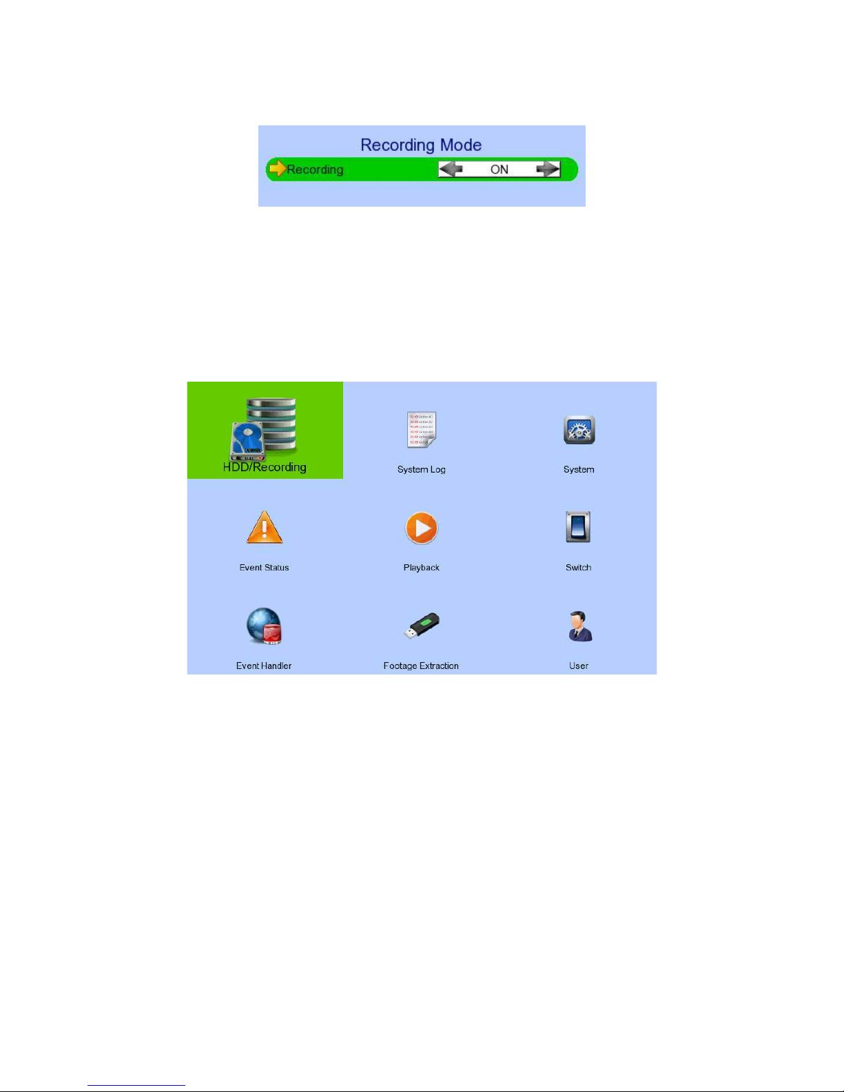
[Screen Selection] [Recording]
Recording Quick menu for selecting recording mode
- Off: Disable recording
- On: Enable recording of all cameras
- Schedule: Enable schedule recording
[Main Menu]
HDD/Recording Change recording and hard disk settings
System Log Display event, connection, operation and setting log
System View server information
Change system settings (e.g. IP, date time, language)
Event Status Display event status
Clear event status
Playback Display recording log
Start video playback
Switch Control the switches
Change switch settings
Event Handler Change event settings
Footage Extraction Extract recorded video to USB flash device
User Change security mode
Change user settings

[Main Menu] [HDD/Recording]
Disk Management View hard disk information
Format, scan or turn on/off disk
Recording Mode Select recording mode
- Off: Disable recording
- On: Enable recording of all cameras
- Schedule: Enable schedule recording
Image Size Set recording resolution
- Ultra High : 960 x 576
- QUAD: 320 x 240
Video Quality Set video quality
Frame Rate Set recording frame rate, applied to all cameras
- Auto: Record at highest achievable frame rate
- X fps: Record at X frames per second
- Custom: Enable custom frame rate for individual camera
Custom Frame Rate Set recording frame rate of individual cameras
Disk Mode Set disk mode
- Cyclic: Remove oldest data when hard disk full
- Fixed: Stop recording when hard disk full
Schedule Recording View or change recording schedules
Recording Retention Set recording retention settings
Recover Recording Recover damaged recorded video

[Main Menu] [HDD/Recording] [Disk Management]
Format Format the selected hard disk *
Enable/ Disable Enable hard disk for recording purpose *
Scan All Scan all installed hard disks *
Format All Format all installed hard disks *
(*
local password of current user required
)
[Main Menu] [HDD/Recording] [Schedule Recording]
Add Add a new recording schedule
Edit Edit the selected schedule
Delete Delete selected schedule
Delete Day Delete all schedules on the same day as the selected schedule

[Main Menu] [HDD/Recording] [Schedule Recording] [Add]
Weekdays Select the weekdays to apply the schedule
Start Time Set the start time of the schedule
End Time Set the end time of the schedule
Frame Rate Set recording frame rate of the schedule
(not applicable for Custom frame rate)
Recording Type Type of recording schedule
- Normal: Record when within schedule
- Motion: Record when motion detected and within
schedule
- Custom: Record based on individual camera setting
Camera Select the cameras to apply the schedule
ADD Confirm add the schedule setting
Motion Setting Set motion detection settings
[Main Menu] [HDD/Recording] [Schedule Recording] [EDIT]
Most settings are the same as [Add] menu.
EDIT Confirm EDIT the schedule setting

[Main Menu] [HDD/Recording] [Recording Retention]
Enable Enable / disable recording retention
Retention Period Remove recorded video after selected days
Schedule Time for Retention Remove recorded video at selected time
[Main Menu] [HDD/Recording] [Recover Recording]
Press “MENU” button can hide or display progress bar during recovering.
OK Start recover (local password of current user is required )
CANCEL Back to previous page
[Main Menu] [System Log]
Event Log Display event log
Connection Log Display remote connection log
Setting Log Display setting log
Operation Log Display operation log

[Main Menu] [System Log] [Event Log]
Date/Time Show event date and time
Ch Show event channel number
Status Show event status
- Trigger: Event triggered
- Reset: Event reset
- Tamper: Event tampered
- Arm: System armed
- Disarm: System disarmed
- Secu Switch On: Security switch turned on
- Secu Switch Off: Security switch turned off
- Entry: Event trigger within entry
delay
- Exit: Event trigger within exit delay
Action Show event associated actions
Show previous / next page of log
Show different types of event log

[Main Menu] [System Log] [Connection Log]
Date/Time Show connection date and time
Access Show IP of the remote host
Status Show connection status
Remark Show type of connection
- Dial in: Triggered by user
- Dial back: Triggered by dialback action
User Show the user connected to video server through remote
software
Show previous / next page of log

[Main Menu] [System Log] [Setting Log]
Date/Time Show date and time of the change
Setting Show setting that is changed
Ch Show channel number of setting if available
Remark Show new value of the setting
Access Show IP of the remote host or “Local” for local host
User Show the user performed the change
Show previous / next page of log
[Main Menu] [System Log] [Operation Log]
Date/Time Show date and time of the operation
Operation Show operation that is done
Access Show IP of the remote host or “Local” for local host
User Show the user performed the operation
Show previous / next page of log

[Main Menu] [System Log] Any Log [Search Log]
Press enter or double click on any log entry to enter [Search Log] menu.
Date Set the search date
Time Set the search time
Search Search for log closest to the date and time
[Main Menu] [System Log] [Event Log] [Log Option]
If an event log entry is associated with the recording action, pressing enter or double clicking will
enter [Log Option] menu.
Enter [Search Log] menu
Enter [Recording Log] menu with date and time of event log

[Main Menu] [System]
Information Display general information of the video recording server
Registration Checking Enable / disable remote registration check
Built In Web Server Enable / disable built in web server
Language Set display language
Camera Setting Change camera settings
Date Time Change date and time settings
Network Change connection, throughput and 3G modem settings
External Keyboard Set external keyboard settings
PTZ Set PTZ arguments
Display Change local monitoring and audio settings
Audio Setting Set audio input and output
Lock Keys Change key lock settings
System Upgrade Upgrade firmware from USB device
Import Export Import or export setting files
Restore Factory Restore default settings

[Main Menu] [System] [Information]
Server Name Display name of the video recording server
Model Name Display model of the video recording server
Serial Number Display serial number of the video recording server
Firmware Version Display firmware version of the video recording server
CPLD Version Display CPLD version
IP Display IP address of the video recording server
Port Display port number of the video recording server
Subnet Display subnet mask of the video recording server
Gateway Display gateway of the video recording server
Primary DNS Display primary DNS of the video recording server
Secondary DNS Display secondary DNS of the video recording server

[Main Menu] [System] [Date/Time]
Time Synchronisation Enable Enable / disable time synchronisation
Time Zone Set the time zone
Country Select a country
Date Set system date (Time sync disabled only)
Time Set system time (Time sync disabled only)
CHANGE TIME Save the time settings (Time sync disabled only)
Primary Time Server Set the primary time server (Time sync enabled only)
Secondary Time Server Set the secondary time server (Time sync enabled only)
Synchronise Time Perform time synchronisation (Time sync enabled only)

[Main Menu] [System] [Network]
Auto IP Enable / disable auto IP from DHCP
IP Address Set IP address of the video recording server
Port Set port number of the video recording server
Subnet Set subnet mask of the video recording server
Gateway Enable Enable / disable the gateway
Gateway Set gateway of the video recording server
Auto DNS Enable / disable auto DNS
Primary DNS Set primary DNS of the video recording server
Secondary DNS Set secondary DNS of the video recording server
LAN Stream Throughput Set the data rate of LAN connection
Broadband Stream Throughput Set the data rate of broadband connection
Narrowband Stream Throughput Set the data rate of narrowband connection
Mobile Stream Throughput Set the data rate of mobile connection
sureLINK Setting Change sureLINK settings
IP Filtering Change IP filtering settings
3G USB Modem Change 3G modem settings
[Main Menu] [System] [Network] [sureLINK Setting]
Enable Enable / disable sureLINK function
sureLINK Address Set the sureLINK address of video recording server
Refresh Period Set the sureLINK refresh rate

[Main Menu] [System] [Network] [IP Filtering]
Mode Set the IP filtering mode
- Disable: Disable IP filtering
- Allow: Only allow selected IP address to connect
- Deny: Disallow selected IP address to connect
Filtered IP Address Set the IP range to be filtered
[Main Menu] [System] [Network] [IP Filtering] [Filtered IP Address]
No. Show the IP filtering entry number
Start IP Address Show starting IP of the filtered IP range
End IP Address Show ending IP of the filtered IP range
Add Add an IP filtering entry
Delete Delete the selected IP filtering entry
Delete All Delete all IP filtering entries
Show previous / next page of filtered IP address

[Main Menu] [System] [Network] [IP Filtering] [Filtered IP Address]
[Add]
Start IP Address Set starting IP to be filtered
End IP Address Set ending IP to be filtered
Add Add the filter entry
[Main Menu] [System] [Network Setting] [IP Filtering] [Filtered IP Address]
[Edit IP Filter]
Press enter or double click on an existing entry to enter [Edit IP Filter] menu.
Start IP Address Change starting IP of the filtering range
End IP Address Change ending IP of the filtered range
Edit Edit the filter entry

[Main Menu] [System] [Network] [3G USB Modem]
Manufacturer Manufacturer name
Model Model
Revision Firmware version
Operator 3G network operator
Signal Strength 3G network signal strength from 0 to 100
IP Address 3G network IP
Driver Version Modem driver version
Enable Enable/ disable 3G modem
Dialup By Set dialup mode
- SMS EVENT: Dialup triggered by sms message
- STARTUP: Dialup after GX startup
Active Profile Set profile for 3G dialup
Profile Setting Change profiles settings
Dialup Test Start dialup test
UPGRADE DRIVER Upgrade 3G modem driver from USB device

[Main Menu] [System] [Network] [3G USB Modem] [Profile Setting]
Access Point Name Dialup Access Point Name
Dial Number Dialup Number
User Name 3G network login user name
Password 3G network login password
[Main Menu] [System] [External Keyboard]
Support External Keyboard Display support of external keyboard
Server ID Set DVR id for PTZ control
Mode Select to set PTZ or server mode

[Main Menu] [System] [Camera Setting]
Camera Select a camera
Installed Enable / disable the video channel
Name Change the name of camera
Brightness Set video brightness
Contrast Set video contrast
Saturation Set video saturation
Sharpness Set the sharpness to make video more sharp
Undo Undo current change
[[Main Menu] [System] [PTZ]

Camera Selected video channel
Pan Speed Set pan speed
Tit Speed Set tilt speed
Patrol Speed Set patrol speed
Dwell Time Set dwell time for patrol
[Main Menu] [System] [Display]
Server Name Set name of video server
Date Time Position Set the position for displaying system time
Camera Name Enable Display / hide camera name
Sequential Time Set the switch time between cameras in sequential mode
Sequential Camera Choose cameras displayed in full screen sequential mode
Default Display Mode Set the default display mode
OSD Font Color Set the font color of OSD items
Fit Screen Set to fit screen or keep aspect ratio
Video Out Resolution Set the output display resolution
Change Resolution Confirm the change in output resolution
Display Refresh Refresh the display in case something goes wrong

[Main Menu] [System] [Audio Setting]
Hardware Support Display audio feature is supported by video server
Channel Set input audio channel
Channel Installed Enable /disable audio selected input channel
PA Channel Set PA channel
PA Installed Enable /disable PA channel
Live Output Enable /disable audio live output channel

[Main Menu] [System] [System Upgrade]
Progress Bar Display the upgrade progress
Upgrade Upgrade the firmware from USB flash device
[Main Menu] [System] [Import Export]
Import Import settings from USB flash device
Export Export settings to USB flash device

[Main Menu] [System] [Import Export] [Export]
Video Export camera settings if selected
Recording Export recording settings if selected
Switch Export switch settings if selected
Date/Time Export date/time settings if selected
Connection Export network settings if selected
Event Handler Export event settings if selected
E-mail/SMS/Dialback Export e-mail, SMS and dialback settings if selected
Server Export server settings if selected
OSD Export OSD settings if selected
Select/Deselect All Select / deselect all settings
Export Export the selected settings to USB flash device

[Main Menu] [Event Status]
Alarm Trigger Show alarm trigger status
Alarm Tamper Show alarm tamper status
Motion Show motion status
Video Loss Show video loss status
Arm/Disarm Tamper Show arm/disarm tamper status
Security Switch Tamper Show security switch tamper status
System Tamper Show system tamper status
Power Failure Show power failure input status
Disk Full Show hard disk usage status
HDD Fault Show hard disk available status
System Restart Show system restart status
Clear Event Clear event that has already reset

[Main Menu] [Playback]
Date Show date of recording log
Time Show time of recording log
1, 2, ... 16 Show cameras that performed recording in red bars
Event Select Display detail of the selected event
Show previous / next page of recording log
Display recording log in smaller time scale
Display recording log in bigger time scale
Search recording log by date and time
Extract video from selected time slot
Set Spot Search View

[Main Menu] [Playback] [Playback Search]
Date Set the search date
Time Set the search time
Today Set date and time to current time
OK Search for log closest to the date and time
[Main Menu] [Switch]
Switch 1 – Switch 4 Toggle the status of the switch
Switch Setting Change switch settings

[Main Menu] [Switch] [Switch Setting]
ID Select switch X to edit
Switch X Name Change the name of switch X
Switch X Type Change the type of switch X
- Latching: Turn on for a period of time
- Push button: Turn off 1 second after it is turned on
Switch X Normal State Change the normal state of switch X
- N.O.: Normal open
- N.C.: Normal close
Action Delay Action setting - set the time between turning off and on
Latch Duration Action setting - set the time for turning on the switch

[Main Menu] [Event Handler]
Arm/Disarm Change arm/disarm settings
Security Switch Change security switch settings
(Arm/Disarm enabled with Hardware Arm mode only)
Alarm Change individual alarm settings
Motion Change motion detection settings
Video Loss Change video loss event settings
System Tamper Change system tamper event settings
Power Failure Change power failure event settings
Disk Usage Change disk usage warning event settings
HDD Fault Change HDD fault event settings
System Restart Change system restart event settings

[Main Menu] [Event Handler] [Arm/Disarm]
Enable Enable / disable the arm/disarm control
Mode Select the arm/disarm mode
Arm State Select circuit open/close as system armed (Hardware Arm only)
Tamper Type Set the tamper detection type (Hardware Arm only)
Tamper Action Set actions taken when arm input tampered (Hardware Arm only)
Associate Switch Associate switch 1 to arm/disarm control status
Schedule Arm/Disarm Enable / disable schedule arm/disarm (Schedule Arm only)
Normal Arm Schedule Set weekly arm/disarm schedule (Schedule Arm only)
Holiday Arm Schedule Set holiday arm/disarm schedule (Schedule Arm only)
[Main Menu] [Event Handler] [Arm/Disarm] [Normal Arm Schedule]
No. Show the schedule number
Start Time Show the start time of system armed
End Time Show the end time of system armed
Weekdays Show the weekdays the schedule applied to
Add Add a normal arm schedule
Delete Delete the selected normal arm schedule
Show previous / next page of schedules
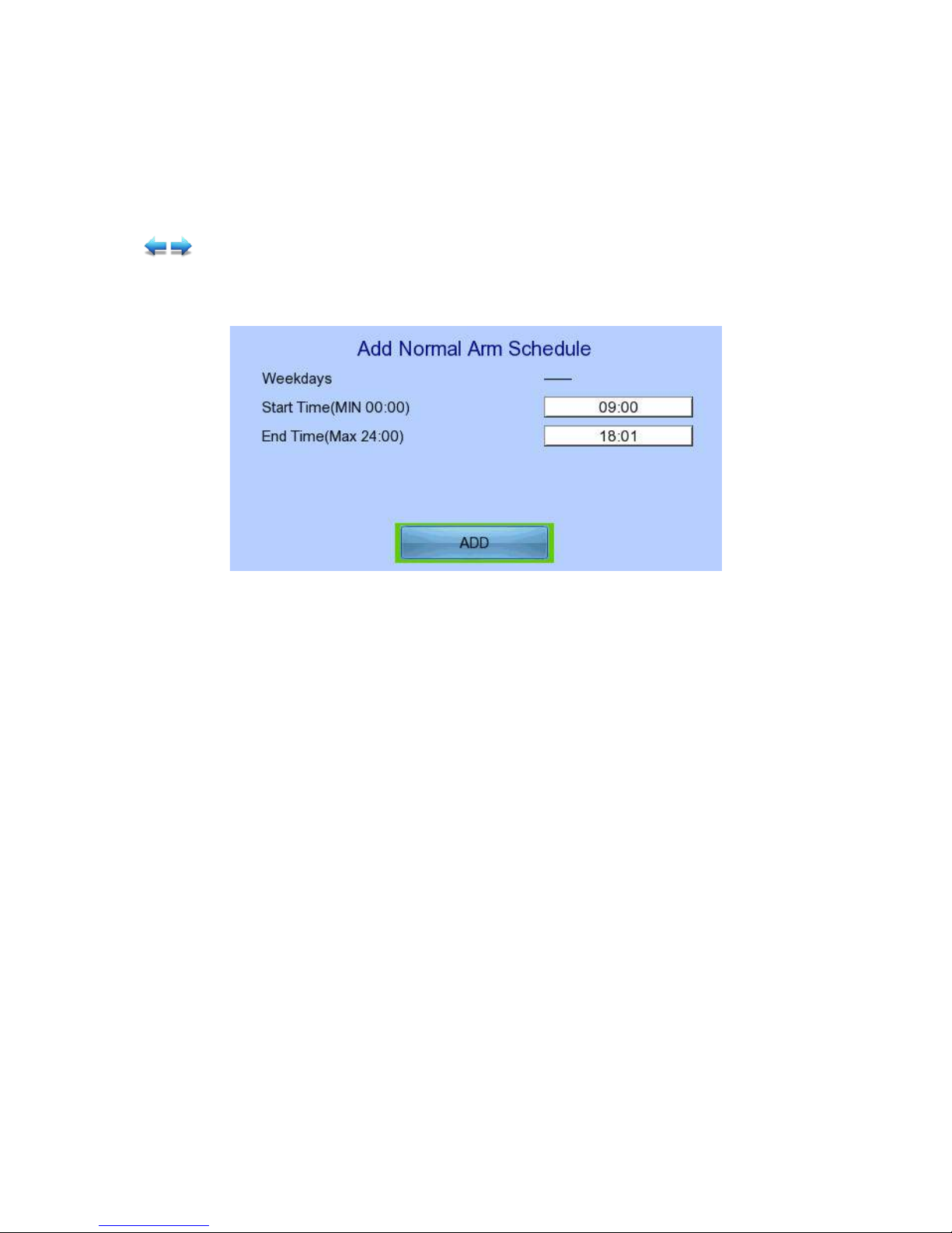
[Main Menu] [Event Handler] [Arm/Disarm] [Normal Arm Schedule] [Add]
Weekdays Set the weekdays the new schedule applied to
Start Time Set the start time of new schedule
End Time Set the end time of new schedule
Add Add the new normal arm schedule

[Main Menu] [Event Handler] [Arm/Disarm] [Holiday Arm Schedule]
No. Show the schedule number
Start Date Show the start date of schedule
End Date Show the end date of schedule
Start Time Show the start time of system armed
End Time Show the end time of system armed
Add Add a holiday arm schedule
Delete Delete the selected holiday arm schedule
Show previous / next page of schedules
[Main Menu] [Event Handler] [Arm/Disarm] [Holiday Arm Schedule] [Add]
Start Date Set the start date of new schedule
End Date Set the end date of new schedule
Start Time Set the start time of new schedule
End Time Set the end time of new schedule
Add Add the new holiday arm schedule

[Main Menu] [Event Handler] [Security Switch]
Enable Enable / disable the security switch
On State Select circuit open/close as security switch on
Tamper Type Set the tamper detection type
Associate Switch Associate switch 2 to security switch status
Tamper Action Set actions taken when security switch is tampered
[Main Menu] [Event Handler] [Alarm]
Alarm Select an alarm
Enable Enable / disable selected alarm
Name Change the name of alarm
Source Type Select source of alarm
- BUILT IN: use video server on board alarm
- CAMERA: use external camera alarm

Sensor Type Select circuit open/close as normal alarm state
Tamper Type Set the tamper detection type
Zone Type Set the zone type:
Entry Delay Set the entry delay time (Entry/Exit Zone only)
Exit Delay Set the exit delay time (Entry/Exit Zone only)
Action Set actions taken when alarm is triggered or tampered
ENABLE/DISABLE ALL Enable / disable all alarm
[Main Menu] [Event Handler] [Motion]
Camera Select a camera
Enable Enable / disable motion event
Motion Detection Setting Set motion detection settings
Zone Set the zone type:
Entry Delay Set the entry delay time (Entry/Exit Zone only)
Exit Delay Set the exit delay time (Entry/Exit Zone only)
Action Set actions taken when motion is detected
ENABLE/DISABLE ALL Enable / disable all motion

[Main Menu] [Event Handler] [Motion] [Motion Detection Setting]
Select Select motion blocks
Deselect Deselect motion blocks
Select All Select all motion blocks
Deselect All Deselect all motion blocks
Sensitivity Set the sensitivity level
Area Set the area sensitivity (Custom sensitivity only)
Level Set the light sensitivity (Custom sensitivity only)
OK Save the motion detection settings
[Main Menu] [Event Handler] [Video Loss]
Camera Select a camera
Enable Enable / disable video loss event
Action Set actions taken when video loss is detected

[Main Menu] [Event Handler] [System Tamper]
Enable Enable / disable system tamper event
Sensor Type Select circuit open/close as normal state
Action Set actions taken when system tamper is triggered
[Main Menu] [Event Handler] [Power Failure]
Enable Enable / disable power failure event
Sensor Type Select circuit open/close as normal state
Action Set actions taken when power failure is detected
[Main Menu] [Event Handler] [Disk Usage]
Enable Enable / disable disk full event
Warning Level Set the warning level
Action Set actions taken when disk usage exceeds warning level

[Main Menu] [Event Handler] [HDD Fault]
Enable Enable / disable the HDD Fault event
Action Set actions taken when disk failure or lost
[Main Menu] [Event Handler] [System Restart]
Enable Enable / disable the system restart available event
Action Set actions taken when system restart abnormally
[Main Menu] [Event Handler] Any Event [Action]
Recording Change event recording settings
Switch Change event switch settings
Dial Back Change dialback settings
E-mail Change e-mail settings

SMS Change SMS settings
Buzzer Change buzzer settings
Event LED Change event LED settings
Live Camera Change event associated live camera settings
PTZ Change event associated PTZ camera settings
[Main Menu] [Event Handler] Any Event [Action] [Recording]
Enable Enable / disable event recording of that event
Recording Mode Set event recording frame rate
- Auto: Record at highest achievable frame rate. The
storage size is large.
- 1 fps: Record at 1 frame per second. Storage size is
comparably small
Duration After Event Clear Set the post-event recording time
Recording Camera Select cameras performing event recording
[Main Menu] [Event Handler] Any Event [Action] [Switch]
Enable Enable / disable switch action of that event
Switch Select switches turning on when event triggers
General Switch Setting Set the latch duration and action delay

[Main Menu] [Event Handler] Any Event [Action] [Dialback]
Enable Enable / disable dialback action of that event
Retry Duration (Sec) Set the time between each dialback retrial
Retry Count Set the number of retrial if dialback fails
Entry X Change the settings of dialback entry X
Dial Back Test Start the dial back test
[Main Menu] [Event Handler] Any Event [Action] [Dialback]
[Dialback Entry]
Enable Enable / disable the dialback entry
IP Address Set the dialback IP address when event triggers
Port Set the dialback port when event triggers

[Main Menu] [Event Handler] Any Event [Action] [E-mail]
Enable Enable / disable e-mail action of that event
Image Attachment Associate
Camera
Change event associated camera for image attachment
SMTP Server Change SMTP settings
E-mail X Set the e-mail address of recipient X
Sender E-mail Set the e-mail address of sender
Action Delay Set the minimum time between 2 e-mails of the same event
Max Number of E-mail Set the maximum e-mails of an event until event clear
E-mail Test Start the e-mail test

[Main Menu] [Event Handler] Any Event [Action] [E-mail] [SMTP Server]
Server Address Set the SMTP server address
Port Set the SMTP server port
Authentication Is authentication required for the SMTP server
User Name Set user name used in authentication
Password Set password used in authentication
Network Setting Change the network settings
Time Out Set the allowed time of sending an e-mail in each trial (in
minute)
Retry Set the number of retrial if fails to send the mail
[Main Menu] [Event Handler] Any Event [Action] [SMS]
Enable Enable / disable SMS action of that event

Phone Number Set recipient phone number
Action Delay Set the minimum time between 2 SMS of the same event
Max SMS Set the maximum SMS of an event until event clear
Voice Call Dial to the phone number while sending SMS notification
SMS Test Start the SMS test
[Main Menu] [Event Handler] Any Event [Action] [Buzzer]
Enable Enable / disable buzzer action of that event
Action Delay Set the time between turning off and next turning on
Duration Set the time for turning on the buzzer
[Main Menu] [Event Handler] Any Event [Action] [Event LED]
Enable Enable / disable LED action of that event
[Main Menu] [Event Handler] Any Event [Action] [Live Camera]
Enable Enable / disable live camera action of that event
Associate Camera Select cameras to be displayed when event triggers

[Main Menu] [Event Handler] Any Event [Action] [PTZ]
Enable Enable / disable live camera action of that event
Associate Camera Select PTZ cameras to be displayed when event triggers
Preset Number Select preset position of PTZ camera when event triggers
[Main Menu] [Footage Extraction]
USB Storage Device Select device for saving the footage
FORMAT Format the selected USB device
Mode Set extraction mode
- Normal: Extract at the same recording frame rate, with
audio
- Quick: Extract selected cameras at low frame rate, no
audio

Channel Choose video channels to extract (Select or Quick mode only)
Start Date Set start date of the footage
Start Time Set start time of the footage
Duration Set video length of the footage
Protection Enable / disable password protection
Password Set extraction password (Password protection enabled only)
EXTRACT Start backup using above settings
[Main Menu] [User]
Current User Display current log in user
Add Account Add new account
Edit/Delete Account Edit or remove an account
Power On Default Right Access right when not logged in
Log out User log out
Log In As Other User User log in

[Main Menu] [User] [Add Account]
User Name User name of new account (4 – 16 characters)
Local Password Password for local log in (4 – 10 characters)
Retype Local Password Confirming the password
Local Time Out Set the auto log out time when no local operation
Account Setting Enable Access right setting
System Setting Enable Access right setting
Recording Setting Enable Access right setting
Video Backup Enable Access right setting
Event Control Enable Access right setting
Camera Control Enable Access right setting
Playback Enable Access right setting
Audio Enable Access right setting
Video Monitoring Enable Access right setting
Switch Enable Access right setting
CONFIRM Create the account

[Main Menu] [User] [Edit/Delete Account]
Most settings are the same as [Add Account] menu.
Local Log in Enable Enable / disable local log in (with remote log in right only)
SAVE Save the account settings
DELETE Delete the account
Show settings of previous / next account

[Main Menu] [User] [Power On Default Right]
Most settings are the same as [Add Account] menu.
SAVE Save the access rights when server startup or local user log out

4.3. Basic Operation
4.3.1. View Live Video
Depends on the model of the TeleEye RX HD video recording server, user can view up to 16
live videos at the same time. User can also choose to supervise the video channel one by one
using the sequential mode function.
A. By Front Panel Buttons
Press button 1 to 9 to select Camera 1 to 9.
Press button 0 first, then press button 0 to 6 to select Camera 10 to 16.
Hold down button 0 for a few seconds to change the display resolution.
Display next page of cameras (e.g. Cam 2 Cam 3).
Hold down the button for a few seconds to start sequential mode.
Switch to next screen mode (e.g. Full 2x2).
Hold down both buttons for a few seconds to refresh the local display.
When OSD menu is opened, the control buttons won’t take effect
B. By Mouse
(Right click)
Open the [Screen Selection] menu

(Left click)
[1] to [16] to display that camera in full screen.
[Mode] to toggle display in 2x2, 3x3 and 4x4 mode respectively
[Next] to show next set of cameras
[Sequential] to start sequential mode.
4.3.2. Recording
To suit different situations, TeleEye RX supports 3 recording modes: manual recording, schedule
recording and event recording. When a camera is recording, the icon will be shown next to its name
and the LED will light up in red color.
- Manual Recording: The start/stop operation is controlled manually by operator.
Recording will be performed on all cameras once started. When
manual recording is on, schedule recording will be disabled.
- Schedule Recording: Recording will be started and stopped according to user defined
schedules. Schedules are set on a weekly basis. When schedule
recording is enabled, manual recording will be disabled.
- Event Recording: Event recording will be activated if an event is triggered with its
recording action enabled. It can be performed with manual recording
or schedule recording simultaneously. Detail description and setup
procedure will be given later in the Advanced Operation section.
To change recording mode quickly, either press on the front panel, or right click mouse to open
[Screen Selection] and click [Recording]
Recording Quick menu for selecting recording mode
- Off: Disable recording
- On: Enable recording of all cameras
- Schedule: Enable schedule recording

To change other recording settings or edit recording schedules, go to the following menus:
[Main Menu] [HDD/Recording]
Disk Management View hard disk information
Format and scan disk
Recording Select the recording mode
Image Size Set recording resolution
- Ultra-high: 960 x 576
- QUAD: 360 x 288
Video Quality Set video quality
Frame Rate Set recording frame rate, applied to all cameras
- Auto: Record at highest achievable frame rate
- X fps: Record at X frames per second
- Custom: Enable custom frame rate for individual camera
Custom Frame Rate Set recording frame rate of individual cameras
Disk Mode Set disk mode
- Cyclic: Remove oldest data when hard disk full
- Fixed: Stop recording when hard disk full
Schedule Recording View or change recording schedules
Recording Retention Set recording retention settings
Recover Retention Recover damaged recorded video

[Main Menu] [HDD/Recording] [Schedule Recording]
Add Add a new recording schedule
Edit Edit the selected schedule
Delete Delete selected schedule
Delete Day Delete all schedules on the same day as the selected schedule

[Main Menu] [HDD/Recording] [Schedule Recording] [Add]
Recording Type Type of recording schedule
- Normal: Record when within schedule
- Motion: Record when motion detected and within
schedule
- Custom: Record based on individual camera setting
Weekdays Select the weekdays to apply the schedule
Start Time Set the start time of the schedule
End Time Set the end time of the schedule
Camera Select the cameras to apply the schedule
Frame Rate Set recording frame rate of the schedule
(not applicable for Custom frame rate)
ADD Confirm add the schedule setting
Motion Setting Set motion detection settings
[Main Menu] [HDD/Recording] [Schedule Recording] [EDIT]
Most settings are the same as [Add] menu.
EDIT Confirm EDIT the schedule setting

4.3.3. Playback
TeleEye RX supports user to view recorded video while not affecting the recording process. A maximum
of 4 video channels can be played at the same time.
[Main Menu] [Playback]
Date Show date of recording log
Time Show time of recording log
1, 2, ... 16 Show cameras that performed recording in red bars
Event Select Display detail of the selected event
Show previous / next page of recording log
Display recording log in smaller time scale
Display recording log in bigger time scale
Search recording log by date and time
Extract selected time slot on the log

[Main Menu] [Playback] [Search By Date]
Date Set the search date
Time Set the search time
Today Set date and time to current time
OK Search for log closest to the date and time
4.3.4. PTZ
When observing video from local monitor, user can select individual video channel by using panel keys
, , , or (mouse left click). Selected video channel will be pointed by icon. User can
press or (mouse left click) to take PTZ control, then the selected channel will be highlighted by
icon (Only digital PTZ control can be taken, or If the video channel not support analogue PTZ
control). For analogue PTZ supported channel, User can click or for taking PTZ command after
the command box pop-up on video monitoring screen. User can deselect the PTZ control channel by
using or , then the video channel will be pointed by icon.
OSD object selection Digital /Analogue PTZ
control
PTZ tilt up
PTZ tilt down
PTZ pan left
PTZ pan right

PTZ function (only for
analogue PTZ)
PTZ command subtract (only
for analogue PTZ)
PTZ command add
(only for analogue PTZ)
PTZ command box
(only for analogue PTZ)
PTZ command down
(only for analogue PTZ)
PTZ command up
(only for analogue PTZ)
For analogue PTZ control, user can select different PTZ command by buttons, and control
the value by buttons.
ZOOM Control zoom in or out
RECALL PRESET:X Recall saved preset position
PROGRAM PRESET:X Edit preset position
AUTO PAN Start auto pan
FOCUS Control focus near or far
IRIS Control iris on or off
RECALL PATROL:X Recall saved patrol
STOP PATROL Stop patrol
CLEAR PATROL Clear patrol 1
START TOUR REC Start tour recording
STOP TORU REC Stop tour recording
SET LIFT LIMIT Set life limit position for auto pan
SET RIGHT LIMIT Set right limit position for auto pan

[Main Menu] [System] [General PTZ Setting]
Camera Selected video channel
Pan Speed Set pan speed
Tit Speed Set tilt speed
Patrol Speed Set patrol speed
Dwell Time Set dwell time for patrol
[Main Menu] [System] [External Keyboard]
Support External Keyboard Display support of external keyboard
Server ID Set DVR id for PTZ control
RS-485 Baud Rate Set RS-485 input baud rate
4.4. Advanced Operation
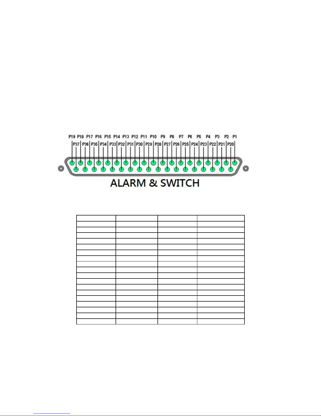
4.4.1. Install Alarm Sensors and Relay Control Port
TeleEye RX supports up to 16 alarm ports with tamper detection for connecting with alarm sensors, 4
additional input sensors and 4 relay ports for control. The definitions of alarm and relay control ports are
shown in the following diagram.
Pin assignment for TeleEye RX
Pin 1 Alarm 1 Pin 20 GND
Pin 2 Alarm 2 Pin 21 GND
Pin 3 Alarm 3 Pin 22 GND
Pin 4 Alarm 4 Pin 23 GND
Pin 5 Alarm 5 Pin 24 GND
Pin 6 Alarm 6 Pin 25 GND
Pin 7 Alarm 7 Pin 26 GND
Pin 8 Alarm 8 Pin 27 GND
Pin 9 Alarm 9 Pin 28 Arm/Disarm
Pin 10 Alarm 10 Pin 29 Security Switch
Pin 11 Alarm 11 Pin 30 Power Failure
Pin 12 Alarm 12 Pin 31 System Tamper
Pin 13 Alarm 13 Pin 32 Alarm 14
Pin 14 Alarm 15 Pin 33 Alarm 16
Pin 15 Relay 0a Pin 34 Relay 0b
Pin 16 Relay 1a Pin 35 Relay 1b
Pin 17 Relay 2a Pin 36 Relay 2b
Pin 18 Relay 3a Pin 37 Relay 3b
Pin 19 N/A

4.4.2. Install Tamper Circuit and External Resistors
TeleEye RX supports tamper detection on all alarm inputs including arm/disarm input, security switch
input, system tamper and power failure input.
DEOL : Dual End of Line termination with NC and NO connection
SEOL : Single End of Line termination with NC and NO connection
NC/NO : Alarm and other input ports without tamper detection circuit connection
For example: By connecting the tamper circuit with DEOL, the circuit is in the normal close condition if
the resistance between point A and B detects 1.2kΩ (shown as below), whereas the circuit is in normal
open condition if the resistance between point A and B detects 7.2kΩ. The resistance transition from
1.2kΩ to 7.2kΩ is generated by an alarm tamper event for normal close circuit. The setup configuration of
those alarms and input ports are shown in the following diagrams. The circuit debouncing time between
each sensor is 20 milliseconds.
Dual End of Line Configuration
Normal Close (NC)
Normal Open (NO)
Term Status Description
S/C Tamper Wire short (point A and B)
LoZ Normal Sensor drive output close
(point B and C)
HiZ Alarm Sensor drive output open
(point B and C)
O/C Tamper Wire open (point A and B)
Term Status Description
S/C Tamper Wire short (point A and B)
LoZ Normal Sensor drive output close
(point B and C)
HiZ Alarm Sensor drive output open
(point B and C)
O/C Tamper Wire open (point A and B)

Single End of Line Configuration
Normal Close (NC)
Normal Open (NO)
Without Tamper Detection Circuit Configuration
Normal Close (NC)
Normal Open (NO)
Legend
NO Normally open alarm
NC Normally close alarm
O/C Open circuit
S/C Close circuit
LoZ Low impedance
HiZ High impedance
Term Status Description
S/C Tamper Wire short (point A and B)
LoZ Normal Sensor drive output close
(point B and C)
O/C Alarm Sensor drive output open
(point B and C)
Term Status Description
S/C Alarm Sensor drive output close
(point A and B)
LoZ Normal Sensor drive output open
(point A and B)
O/C Tamper Wire open (point A and B)
Term Status Description
S/C Normal Sensor drive output close
(point A and B)
O/C Alarm Sensor drive output open
(point A and B)
Term Status Description
S/C Alarm Sensor drive output close
(point A and B)
O/C Normal Sensor drive output open
(point A and B)

The table below shows the summary between the resistance network and the condition result.
This table is provided as a reference. There may be a 10% tolerance for the resistance value.
Condition Resistance (Ω)
0 - 400 401 - 2780 2781 – 29.5k 29.5k - infinity
DEOL (Normal
Close)
Tamper Short Normal (Close) Alarm (Open) Tamper Open
DEOL (Normal
Open)
Tamper Short Alarm (Close) Normal (Open) Tamper Open
SEOL (Normal
Close)
Tamper Short Normal (Close) Alarm (N/A) Alarm (Open)
SEOL (Normal
Open)
Alarm (Close) Normal (Open) Alarm (N/A) Tamper Open
NC without
tamper
Normal (Close) Alarm (N/A) Alarm (N/A) Alarm (Open)
NO without
tamper
Alarm (Close) Alarm (N/A) Alarm (N/A) Normal (Open)
Alarm (N/A): Alarm is not applicable

4.4.3. Event Handling
4.4.3.1.
Arm/Disarm
Arm/Disarm input is used for enhancing security level of the surveillance area. This input introduces the
concept of 3 zone types of alarm and motion: fire zone, normal and entry/exit zone.
Armed
If the system is armed, alarm sensor and motion that is set as normal zone can be triggered immediately if
someone triggers the sensor or motion detected. It is usually used when there is no operator at
surveillance area.
Disarmed
If the system is disarmed, alarm and motion events detected from sensors will not result in an alarm and
motion except the fire zone type alarm, motion and arm/disarm tamper. If there are operators at
surveillance area, it is usually disarmed.

Arm/Disarm Mode
TeleEye RX supports 3 different modes of arm/disarm operation:
- Hardware: Use Arm input to arm/disarm, suitable for local operation
- Software: Use software to arm/disarm, suitable for remote operation
- Schedule: Follow preset schedule to arm/disarm, suitable for unmanned location
Under software and schedule mode, the security switch is not applicable.
There are 2 types of arm schedules:
- Normal Schedule: User can set the arm period in terms of weekday.
The system would arm according to this weekly
schedule.
- Holiday Schedule: User can set the arm date and period for specially
handled holiday. If the date is set to holiday
schedule, it will follow holiday schedule instead
of normal schedule.
Arm/Disarm Tamper Type
Arm/Disarm tamper event triggers if someone cuts the wire between the arm/disarm input and the video
recording server. This event can be triggered once the wire is being cut. Arm/Disarm tamper type has
choice of none, SEOL and DEOL.
Arm State
If arm state is set to close, it indicates arm of TeleEye RX when the state of the circuit is close and disarm
of TeleEye RX when the circuit is open. Oppositely, if arm state is set to open, it indicates arm and disarm
of TeleEye RX when the state of the circuit is open and close respectively.
Physical Configuration for Arm/Disarm
The arm/disarm input and ground of TeleEye RX video recording server needs to connect to a control unit
which is commonly a switch or password panel for arm/disarm input.

[Main Menu] [Event Handler] [Arm/Disarm]
Enable Enable / disable the arm/disarm control
Mode Select the arm/disarm mode
Arm State Select circuit open/close as system armed (Hardware Arm only)
Tamper Type Set the tamper detection type (Hardware Arm only)
Tamper Action Set actions taken when arm input tampered (Hardware Arm only)
Associate Switch Associate switch 1 to arm/disarm control status
Schedule Arm/Disarm Enable / disable schedule arm/disarm (Schedule Arm only)
Normal Arm Schedule Set weekly arm/disarm schedule (Schedule Arm only)
Holiday Arm Schedule Set holiday arm/disarm schedule (Schedule Arm only)

[Main Menu] [Event Handler] [Arm/Disarm] [Normal Arm Schedule]
No. Show the schedule number
Start Time Show the start time of system armed
End Time Show the end time of system armed
Weekdays Show the weekdays the schedule applied to
Add Add a normal arm schedule
Delete Delete the selected normal arm schedule
Show previous / next page of schedules
[Main Menu] [Event Handler] [Arm/Disarm] [Normal Arm Schedule] [Add]
Weekdays Set the weekdays the new schedule applied to
Start Time Set the start time of new schedule
End Time Set the end time of new schedule
Add Add the new normal arm schedule

[Main Menu] [Event Handler] [Arm/Disarm] [Holiday Arm Schedule]
No. Show the schedule number
Start Date Show the start date of schedule
End Date Show the end date of schedule
Start Time Show the start time of system armed
End Time Show the end time of system armed
Add Add a holiday arm schedule
Delete Delete the selected holiday arm schedule
Show previous / next page of schedules
[Main Menu] [Event Handler] [Arm/Disarm] [Holiday Arm Schedule] [Add]
Start Date Set the start date of new schedule
End Date Set the end date of new schedule

Start Time Set the start time of new schedule
End Time Set the end time of new schedule
Add Add the new holiday arm schedule
4.4.3.2.
Security Switch
It is an input to the video recording server for wiring a security switch. The purpose of the security switch
is to terminate the exit delay for exit zone alarm. If the security switch is on and the system is armed, all
exit delay will be terminated. If the security switch is off and an entry alarm is triggered, entry delay will
start.
Security Switch Tamper Type
Security switch tamper event triggers if someone cuts the wire between the security switch input and the
video recording server. This event can be triggered once the wire is being cut. Security switch tamper type
has choice of none, SEOL and DEOL.
On State
If security switch on state is set to close, it indicates security switch on and off of TeleEye RX when the
state of the circuit is closed and open respectively. Oppositely, if security switch on state is set to open, it
indicates security switch on and off of TeleEye RX when the state of the circuit is open and closed
respectively.
Physical Configuration for Security Switch
The security switch input and ground of TeleEye RX video recording server needs to connect to a control
circuit which is commonly the lock of the surveillance area for security switch input.
[Main Menu] [Event Handler] [Security Switch]

Enable Enable / disable the security switch
On State Select circuit open/close as security switch on
Tamper Type Set the tamper detection type
Associate Switch Associate switch 2 to security switch status
Tamper Action Set actions taken when security switch is tampered

4.4.3.3.
Alarm
It is an input to the video recording server from external alarm sensors. Alarm can be used to detect many
events occur at the surveillance area, such as fire and illegal entering by someone. The alarm event
supports BS 8418:2003 which has arm/disarm and security switch functions.
Sensor Tamper Type
Alarm tamper event will be triggered if someone cuts the wire between the alarm input and the video
recording server. This event behaves as fire zone type that can be triggered once the wire is being cut.
Alarm tamper type has choice of none, SEOL and DEOL.
Sensor Type
If the alarm sensor input circuit type is normal close (NC), when the state of the circuit is opened, it
indicates alarm trigger of TeleEye GX, while nothing happens when the state of the circuit is closed. If the
alarm sensor input circuit type is normal open (NO), when the state of the circuit is closed, it indicates
alarm trigger of TeleEye GX, while nothing happens when the state of the circuit is open.
Zone Type
All alarm sensors can be associated with zone types if Arm/Disarm input is installed.
- Normal Zone: This zone allows alarms to be triggered after system armed.
- Fire Zone: This zone allows alarms to be triggered no matter which arm state of the
system is, i.e. armed or disarmed. It is suitable for installation of fire
detectors
- Entry/Exit Zone: This zone allows user to set the delay time for entering or leaving the
surveillance area without triggering any alarm event. If alarm recording
action is enabled, recording starts at entry or exit time throughout the delay.

Example of Entry/Exit Zone WITH Security Switch Usage
For Entry Zone:
The entry delay is the period of time between entering the surveillance zone and reaching the video
recording server. In order to disarm the system for maintenance or repair, user / installer needs to turn off
the security switch and enter the surveillance zone. The delay timer starts from the 1st trigger by the 1st
alarm sensor (i.e. Alarm 4). Note that if user enables recording action, recording action is automatically
activated during entry delay.
The detail description is shown as follows:
1. User turns off security switch
2. The alarm is set at entry delay
3. The 1st trigger is made by Alarm 4 (i.e. user enters the surveillance zone and the entry delay time
begins)
4. 2nd, 3rd and 4th trigger are made and each entry delay starts respectively
5. User disarms the system for maintenance
For example: If the time for going from security switch to video recording server is about 8 minutes,
Delay 4 should be around 8 minutes, while Delay 3 should be longer than the time for going from security
switch to Alarm 3, and so on.

For Exit Zone:
The exit delay is the period of time for leaving a surveillance zone without making false alarm (i.e. Alarm
1 to Alarm 4). The purpose is to let the user / installer have enough time to leave the surveillance zone
after the video recording server is armed. User / installer can set the delay time for each alarm. Note that
if user enables recording action, recording will be activated when an alarm is triggered during exit delay.
The detail description is shown as follows:
1. User arms the system
2. The alarm is set at exit delay and timer of all alarms begin
3. The 1st trigger is made by Alarm 1 (i.e. user leaves the surveillance zone)
4. 2nd, 3rd and 4th triggers are made respectively
5. User turns on the security switch or waits for all alarm exit delays to expire
For example, if the time for leaving the surveillance zone is about 8 minutes, user should adjust the delay
time so that Delay 1 = leaving time between video recording server and Alarm 1, Delay 2 = leaving time
between video recording server and Alarm 2, Delay 3 = leaving time between video recording server and
Alarm 3 and Delay 4 should be 8 minutes. The alarm will be activated after the exit delay expired.

Example of Entry/Exit Zone WITHOUT Security Switch Usage
For Entry Zone:
The entry delay is the period of time between entering the surveillance zone and reaching the video
recording server. In order to disarm the system for maintenance or repair, user / installer enters the
surveillance zone. The delay timer starts from the 1st trigger by the 1st alarm sensor (i.e. Alarm 4). Note
that if user enables recording action, recording action is automatically activated during entry delay.
The detail description is shown as follows:
1. The alarm is set at entry delay
2. The 1st trigger is made by Alarm 4 (i.e. user enters the surveillance zone and the entry delay time
begins)
3. 2nd, 3rd and 4th trigger are made and each entry delay starts respectively
4. User disarms the system for maintenance
For example: If the time for going from security switch to video recording server is about 8 minutes,
Delay 4 should be around 8 minutes, while Delay 3 should be longer than the time for going from security
switch to Alarm 3, and so on.

For Exit Zone:
The exit delay is the period of time for leaving a surveillance zone without making false alarm (i.e. Alarm
1 to Alarm 4). The purpose is to let the user / installer have enough time to leave the surveillance zone
after the video recording server is armed. User / installer can set the delay time for each alarm. Note that
if user enables recording action, recording will be activated when an alarm is triggered during exit delay.
The detail description is shown as follows:
1. User arms the system
2. The alarm is set at exit delay and timer of all alarms begin
3. The 1st trigger is made by Alarm 1 (i.e. user leaves the surveillance zone)
4. 2nd, 3rd and 4th triggers are made respectively
5. User waits for all alarm exit delays to expire
For example, if the time for leaving the surveillance zone is about 8 minutes, user should adjust the delay
time so that Delay 1 = leaving time between video recording server and Alarm 1, Delay 2 = leaving time
between video recording server and Alarm 2, Delay 3 = leaving time between video recording server and
Alarm 3 and Delay 4 should be 8 minutes. The alarm will be activated after the exit delay expired.

Different Combination of Cases of Arm/Disarm, Security Switch and Alarm for the 3 Zone Type
Initial State Step 1 Step 2 Step 3 Result
Alarm Arm Security
Switch
Fire Zone
No trigger Arm On Trigger alarm \ \ Alarm trigger
Arm Off Trigger alarm \ \ Alarm trigger
Arm Uninstall Trigger alarm \ \ Alarm trigger
Disarm \ Trigger alarm \ \ Alarm trigger
Uninstall \ Trigger alarm \ \ Alarm trigger
Uninstall Uninstall Trigger alarm \ \ Alarm trigger
Normal Zone
No trigger Arm On Trigger alarm \ \ Alarm trigger
Arm Off Trigger alarm \ \ Alarm trigger
Arm Uninstall Trigger alarm \ \ Alarm trigger
Disarm \ Trigger alarm \ \ No alarm trigger
Uninstall \ Trigger alarm \ \ Alarm trigger
Uninstall Uninstall Trigger alarm \ \ Alarm trigger
Entry/Exit Zone
No trigger Arm On Trigger alarm \ \ Alarm trigger
Disarm Off Arm.
Exit delay starts
Trigger alarm.
Recording starts
if action enabled
Security switch
on.
Exit delay ends.
Recording stops
Alarm can be
triggered any
time after that
Exit delay ends
after preset exit
time.
Recording stops
Alarm can be
triggered any
time after that
Arm On Security switch
off
Trigger alarm.
Entry delay starts.
Recording starts
if action enabled
Disarm No alarm trigger.
Recording stops
Entry delay ends
after preset entry
time
Alarm trigger.
Recording don’t
stop unless
disarm
Disarm Uninstall\ Arm.
Exit delay starts
Trigger alarm.
Recording starts
if action enabled
Exit delay ends
after preset exit
time.
Recording stops
System enter
entry delay
automatically
after next alarm
trigger
Arm Uninstall Trigger alarm.
Entry delay starts.
Recording starts
if action enabled
Disarm \ No alarm trigger.
Recording stops
Entry delay ends
after preset entry
time
\ Alarm trigger.
Recording don’t
stop unless
disarm
Disarm Trigger alarm \ \ No alarm trigger
Uninstall Trigger alarm \ \ Alarm trigger
Uninstall Uninstall Trigger alarm \ \ Alarm trigger
 Loading...