

Page 1

TeleEye RX Series
Mobile Video Recording Server
RX504
User Guide
Page 2

Notice:
Signal Communications Limited reserves the right to make improvements to the product
described in this manual at any time and without prior notice.
This manual is copyrighted. All rights are reserved. This manual should not be copied,
reproduced or translated in whole or part without prior consent from Signal Communications
Limited.
TeleEye is a trademark of Signal Communications Limited and is registered in China,
European Communities, Hong Kong, US and other countries.
All other trademarks are the property of their respective owners.
Copyright (c) 2007 Signal Communications Limited (A member of TeleEye Group). All rights
reserved.
Release Version 1.1
Limits of Liability and Disclaimer of Warranty
Signal Communications Limited has taken care in preparation of this manual, but makes no
expressed or implied warranty of any kind and assume no responsibility for errors or omissions.
No liability is assumed for incidental or consequential damages in connection with or arising out
of the use of the information or accessories contained herein.
Features and specifications are subject to change without prior notice.
Page 3

Table of content
SECTION 1................................................................................................................................................................ 1
INTRODUCTION.........................................................................................................................................................1
1. Introduction...............................................................................................................................................1
2. Features.....................................................................................................................................................1
3. Package Contents......................................................................................................................................1
4. Front panel description .............................................................................................................................2
5. Rear panel description ..............................................................................................................................2
SECTION 2................................................................................................................................................................ 3
INSTALLATION ..........................................................................................................................................................3
1. Install Hard Disk....................................................................................................................................... 3
2. Remove Hard Disk .....................................................................................................................................4
3. Mobile data modem installation................................................................................................................5
4. Wireless LAN adaptor installation.............................................................................................................6
5. Mount to vehicle........................................................................................................................................6
6. Video installation.......................................................................................................................................8
7. Alarm installation......................................................................................................................................8
8. Power connection......................................................................................................................................9
SECTION 3.............................................................................................................................................................. 10
BASIC SETUP ..........................................................................................................................................................10
1. Before setup.............................................................................................................................................10
2. Format Hard Disk ...................................................................................................................................10
3. Hard Disk available event.......................................................................................................................11
4. Network setup..........................................................................................................................................12
5. Mobile data modem setup........................................................................................................................13
SECTION 4.............................................................................................................................................................. 15
OPERATION.............................................................................................................................................................15
1. Live operation through mobile data modem ............................................................................................15
2. Live operation through LAN / wireless LAN............................................................................................16
3. Recording ................................................................................................................................................17
4. Video extraction.......................................................................................................................................18
APPENDIX 1 ...........................................................................................................................................................20
LIMITED WARRANTY ..............................................................................................................................................20
APPENDIX 2 ...........................................................................................................................................................21
sureLINK TECHNOLOGY ........................................................................................................................................ 21
APPENDIX 3 ...........................................................................................................................................................25
FIRMWARE UPGRADE.............................................................................................................................................. 25
APPENDIX 4 ...........................................................................................................................................................26
SECURITY MODE .................................................................................................................................................... 26
APPENDIX 5 ...........................................................................................................................................................30
SPECIFICATION........................................................................................................................................................30
Page 4
TeleEye RX504 User Guide Page 1
Section 1
Introduction
1. Introduction
TeleEye RX504 is a robust video recording server designed for fleet security applications.
By using the award-winning SMAC-M multi-streaming video compression technology,
TeleEye RX504 delivers no compromise performance on simultaneous recording and
transmission via mobile network.
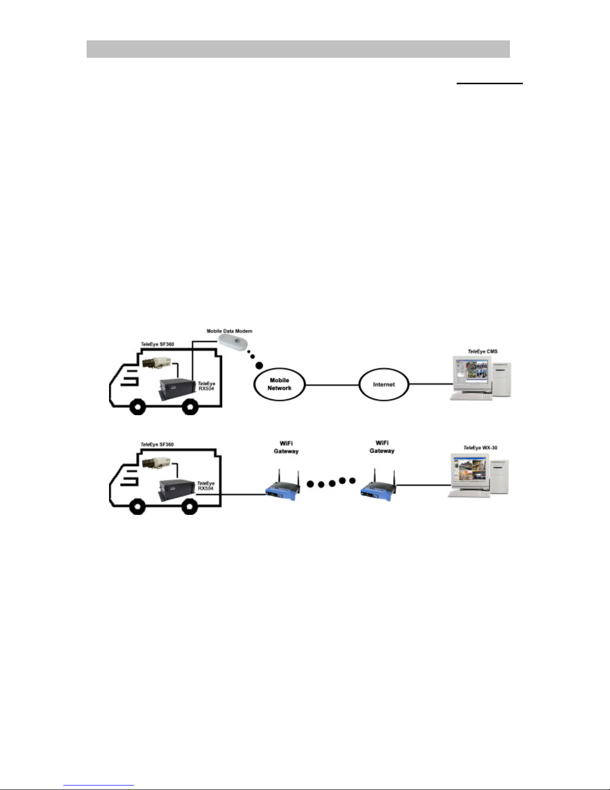
TeleEye RX504 can continuously record videos of every single detail during the vehicle
in service. By connecting TeleEye RX504 to a mobile data modem, the driver can push
a button to trigger the TeleEye RX504 to send an alarm and seamless video back to the
central monitoring station via mobile networks such as HSDPA, UMTS, EDGE or GPRS in
an emergency situation. In conjunction to a WiFi gateway, the recorded data can be
reviewed and extracted to the central storage server via a WiFi network after the vehicle
returning back to the depot.
Live monitoring using mobile network
Video extraction and playback via WiFi
2. Features
l 4 video, 16 alarm inputs; 4 relay outputs
l Recording up to 25/30fps on D1; 100/120fps on CIF resolution
l Live monitoring via HSDPA, UMTS, EDGE and GPRS (require mobile data modem)
l Playback and video extraction via WiFi (require WiFi gateway)
l Fast detachment and shock protection design
3. Package contents
1. TeleEye RX504
2. NULL modem cable C03FF
3. WX-30 installation CD version 3.10.04
4. Hard disk mounting screws with rings
Page 5
TeleEye RX504 User Guide Page 2
5. User manual
6. Hard disk recommendation list
7. Warranty card
8. Registration card
9. R-E220 mobile data modem (optional)
10. Wireless LAN adaptor (optional)
11. Vibration bracket (optional)
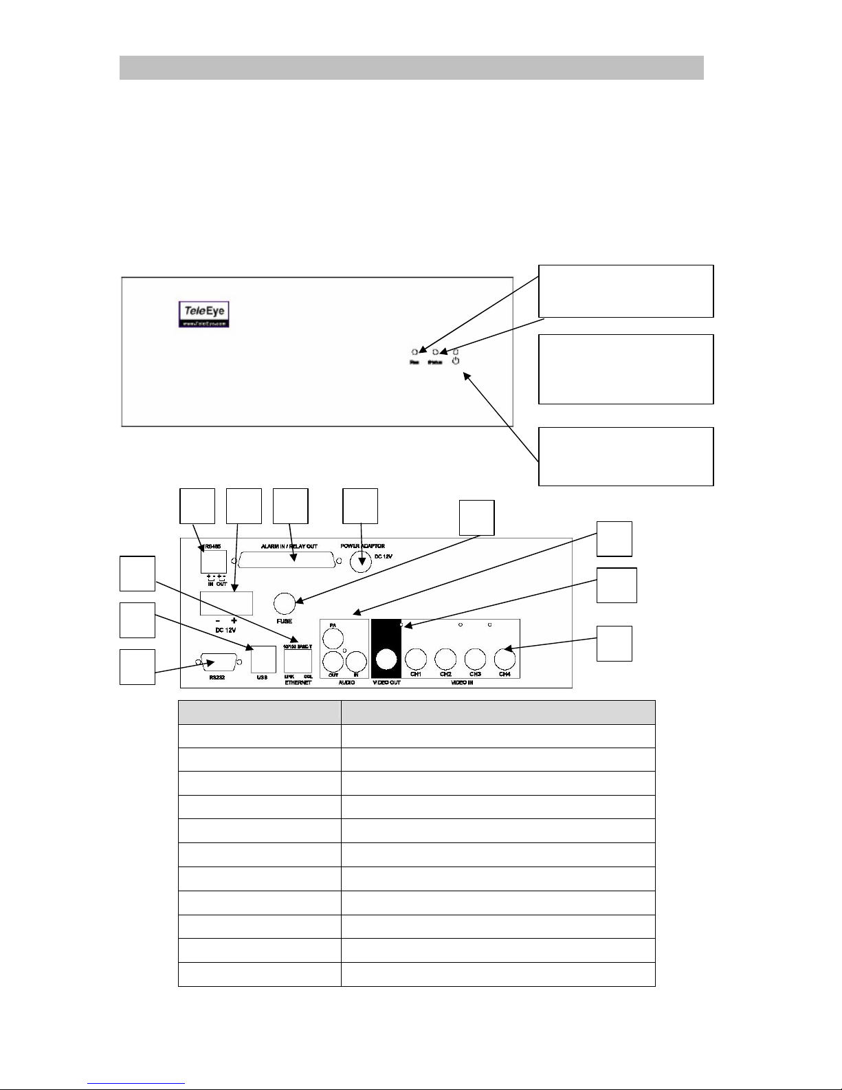
4. Front panel description
5. Rear panel description
Item Description
1. RS-485 (IN / OUT) For telemetry use
2. Power terminal Connect to input power (10-24V DC)
3. Alarm IN Relay Out External alarm input and relay output
4. Power adaptor Reserved
5. FUSE 3Amp protection fuse socket
6. Ethernet RJ45 socket for network connection
7. USB For connecting 3G USB modem
8. RS-232 Connect NULL modem cable for setup use
9. Audio Reserved
10. Video Out Video output BNC type connector
11. Video In Video input BNC connectors
1. REC LED:
On when recording
3. Power LED
On when power up
2. Status LED:
Blinks at event trigger
1
3 2 4 5 6 7 8 9 11 10
Page 6
TeleEye RX504 User Guide Page 3
Section 2
Installation
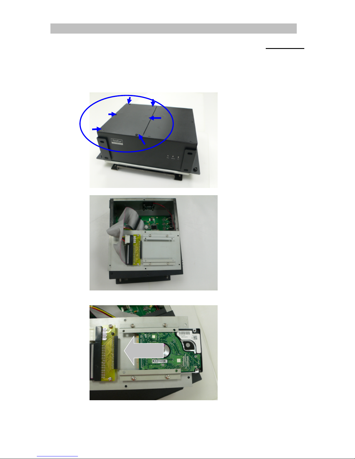
1. Install Hard Disk
1. Remove left cover screw
2. Turn the left cover over
3. Slide the HDD into the slot. Take care for the hard disk pins, make sure all pins be
inserted to connector properly
Page 7
TeleEye RX504 User Guide Page 4
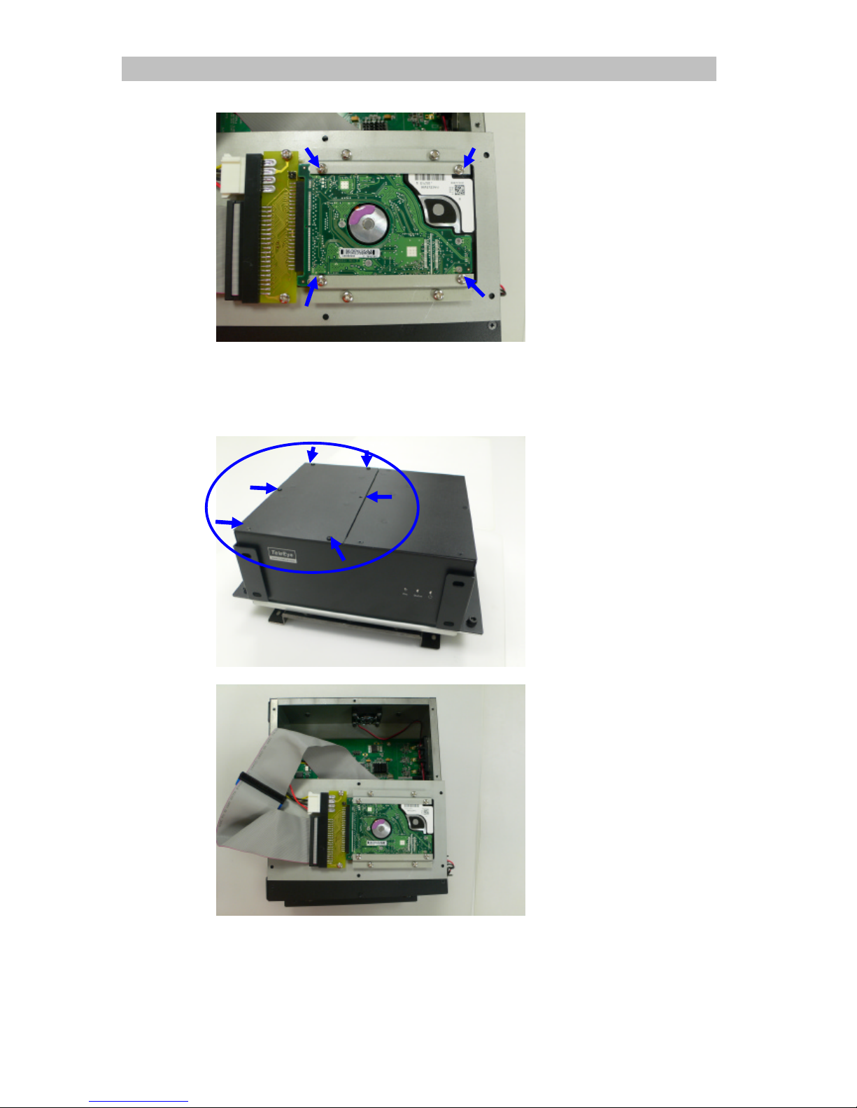
4. Screw the HDD screws with provided screws and rings.
5. Restore and screw up the left cover
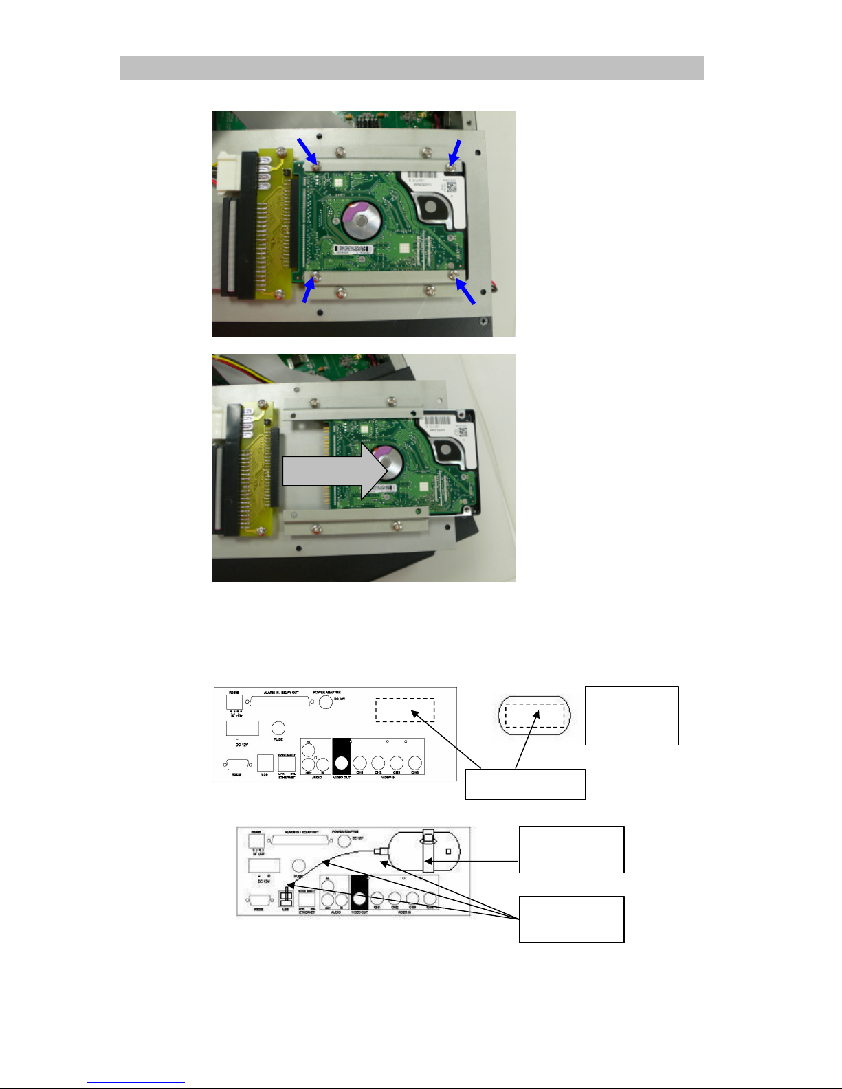
2. Remove Hard Disk
1. Remove left cover screw as shown in following figure
2. Turn the left cover over as shown in the following figure
Page 8
TeleEye RX504 User Guide Page 5
3. Remove HDD screws
4. Slide the Hard disk out
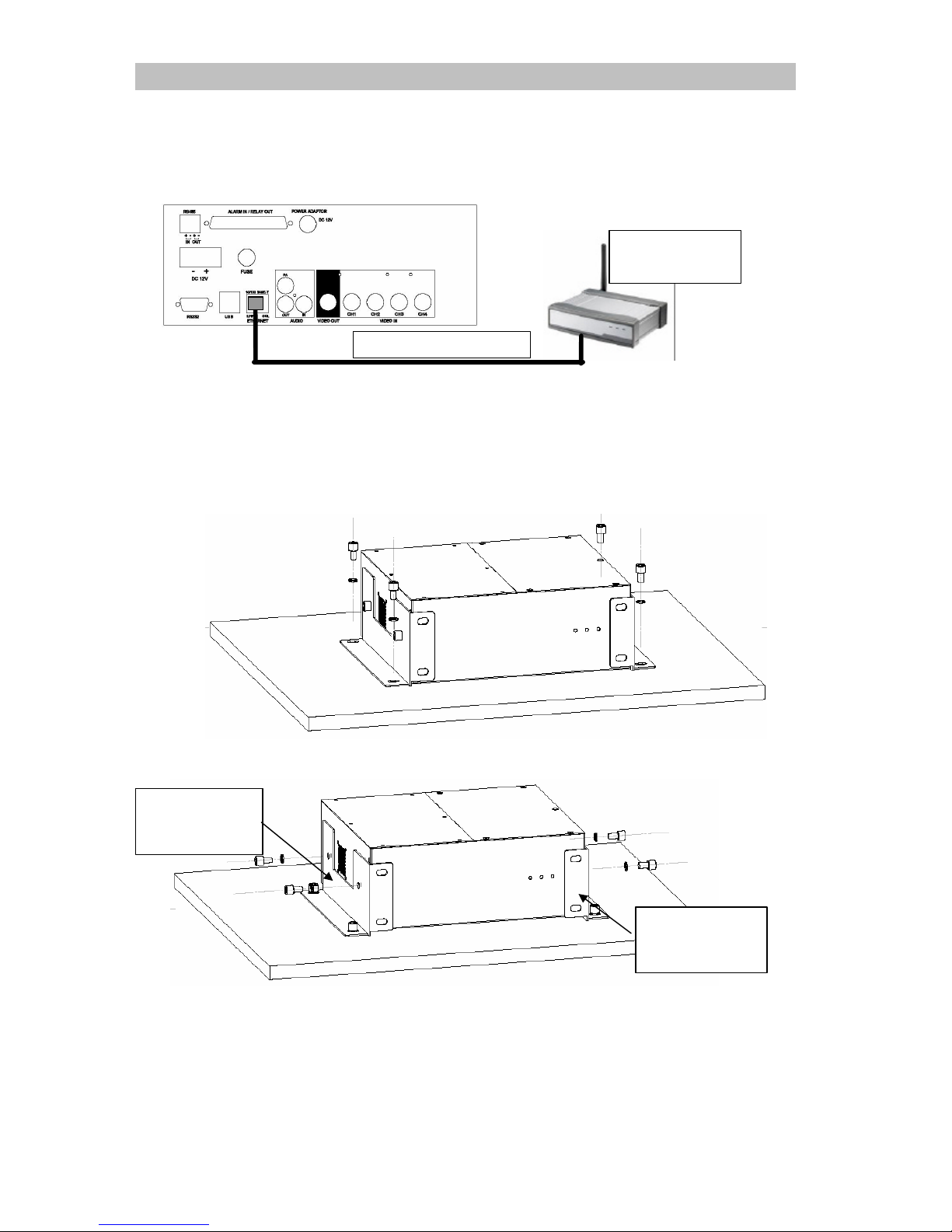
3. Mobile data modem installation
1. Stick provided Velcro to R-E220 and RX504’s rear panel, then stick together as
following figure:
2. Tighten the mounting tape at RX504 real panel
3. Use provided cable tie to fix USB cable on RX504’s rear panel
Mounting
Tape
Cable tie
position
Rear side
of R-E220
Velcro position
Page 9
TeleEye RX504 User Guide Page 6
4. Wireless LAN adaptor installation
1. Only use Wireless LAN Client with CAT5 cable interface, connect the Wireless
Client to RX504’s Ethernet socket.
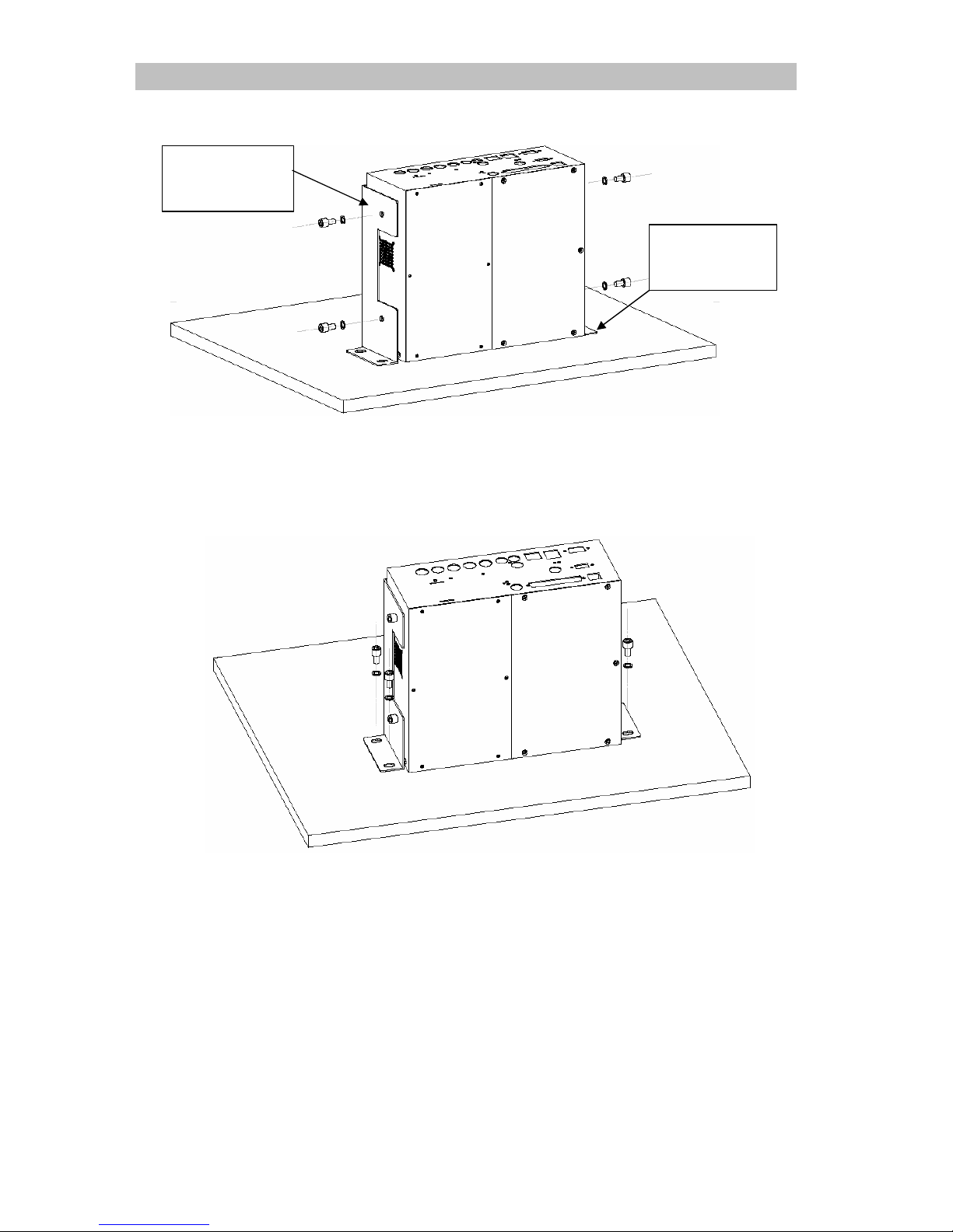
5. Mount to vehicle
1. Horizontal mount
i. Measure the position of the mounting screws and drill holes on the mounting
surface
ii. Screw up the screws on the mounting surface
2. Vertical mount
i. Remove four side mounting screws on RX504 as shown follow
CAT5 Ethernet Cable
Wireless LAN
adaptor
Left mounting
plate
Right
mounting plate
Page 10
TeleEye RX504 User Guide Page 7
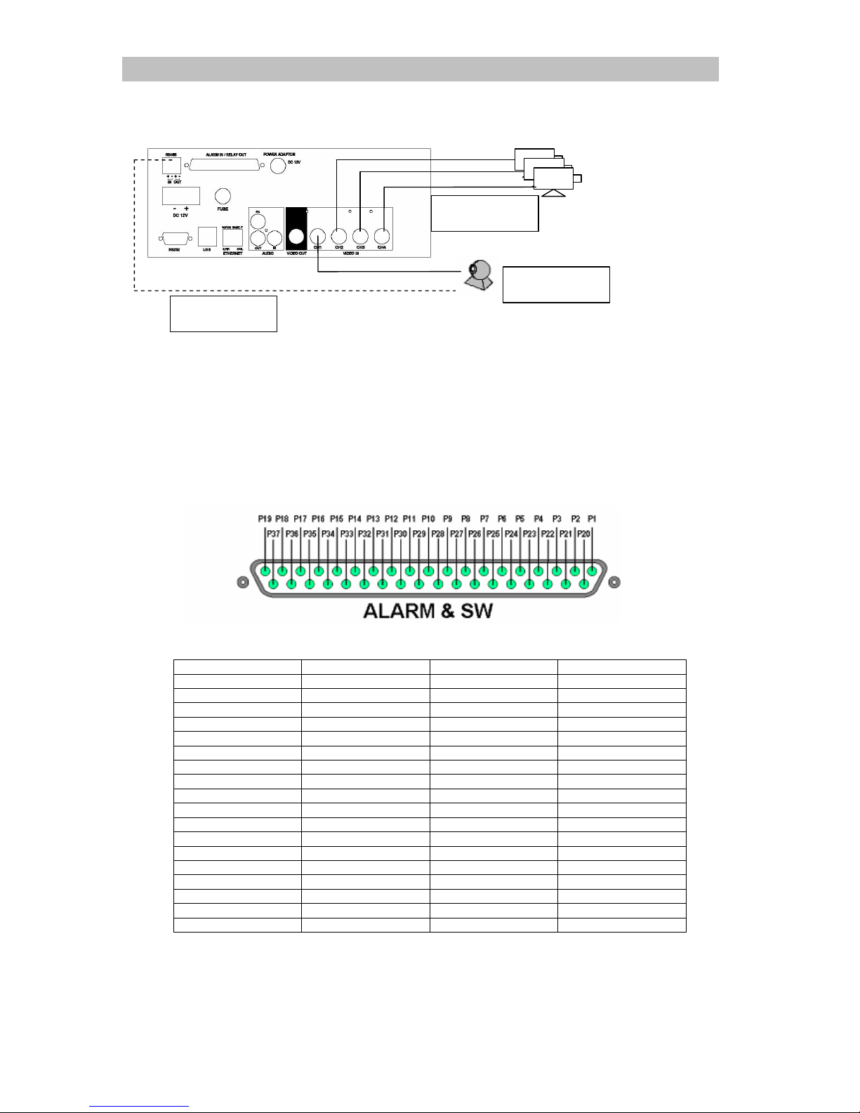
ii. Switch left and right mounting plate as shown in the following figure
iii. Rotate to RX504 front panel face down and screw up the side mounting
screw to RX504
iv. Measure the position of the mounting screws and drill holes on the mounting
surface
v. Screw up the screws on the mounting surface
Right
mounting plate
Left mounting
plate
Page 11
TeleEye RX504 User Guide Page 8
6. Video installation
For fix cameras, connect cameras to video inputs using RG59 cable. For PTZ cameras,
connect camera’s video output to RX504’s video input using RG59 cable, and connect
RS-485 to RX504’s RS-485 out.
7. Alarm installation
TeleEye RX supports up to 16 alarm ports in that order with tamper detection for
connecting with alarm sensors, 4 additional input sensors and 4 relay ports for control.
The definitions of alarm and relay control ports are shown in the following diagram.
Pin assignment for TeleEye RX
Pin 1 ALARM 1 Pin 20 GND
Pin 2 ALARM 2 Pin 21 GND
Pin 3 ALARM 3 Pin 22 GND
Pin 4 ALARM 4 Pin 23 GND
Pin 5 ALARM 5 Pin 24 GND
Pin 6 ALARM 6 Pin 25 GND
Pin 7 ALARM 7 Pin 26 GND
Pin 8 ALARM 8 Pin 27 GND
Pin 9 ALARM 9 Pin 28 ARM/DISARM
Pin 10 ALARM 10 Pin 29 SECURITY SWITCH
Pin 11 ALARM 11 Pin 30 POWER FAILURE
Pin 12 ALARM 12 Pin 31 SYSTEM TAMPER
Pin 13 ALARM 13 Pin 32 ALARM 14
Pin 14 ALARM 15 Pin 33 ALARM 16
Pin 15 RELAY 0a Pin 34 RELAY 0b
Pin 16 RELAY 1a Pin 35 RELAY 1b
Pin 17 RELAY 2a Pin 36 RELAY 2b
Pin 18 RELAY 3a Pin 37 RELAY 3b
Pin 19 N/A
Cameras
RG59 Cable
RS-485 bus
PTZ camera
Page 12
TeleEye RX504 User Guide Page 9
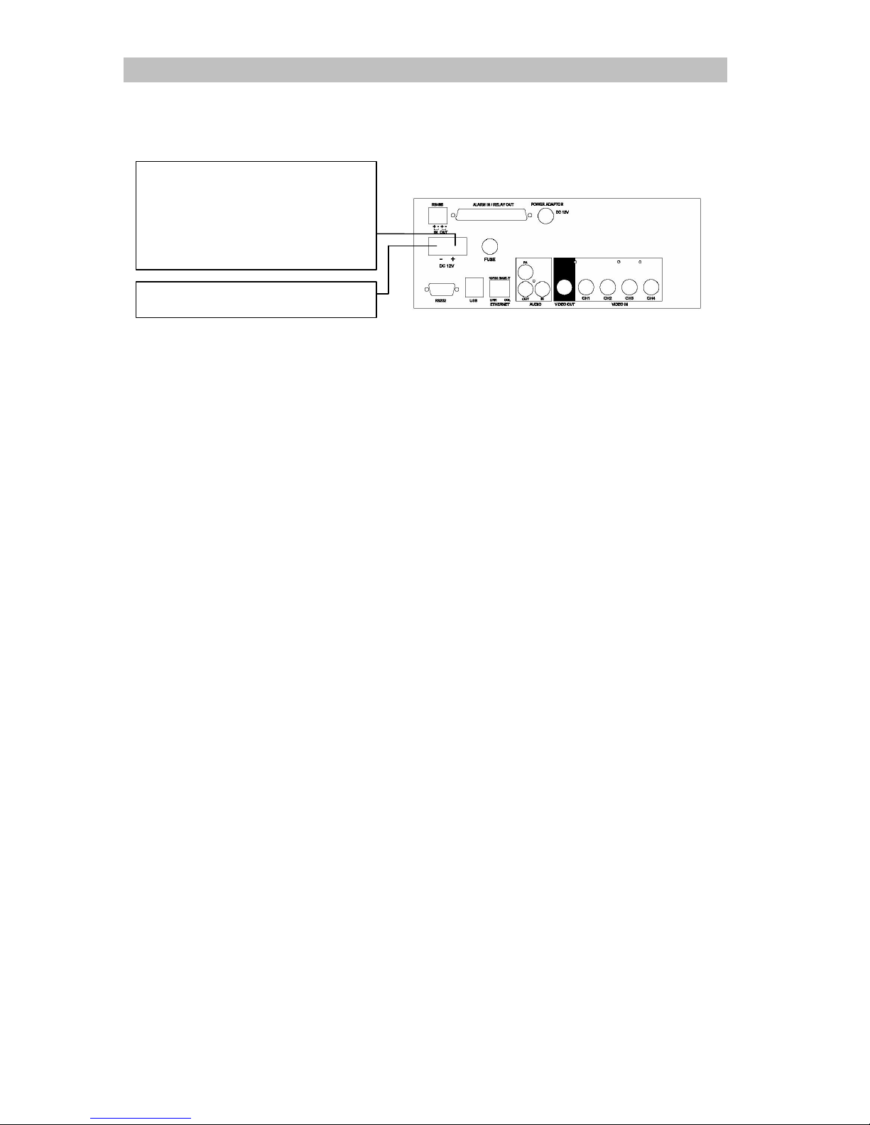
8. Power connection
1. Connect RX504 Ground terminal to car ground.
2. Connect RX504 +12 V terminal to the +12 V power terminal which is
energized in the accessory position of the ignition key.
Connect to the +12 V power
terminal which is energized in the
accessory position of the ignition
key. Be sure to connect the
Ground first
Connect to ground
Page 13
TeleEye RX504 User Guide Page 10
Section 3
Basic Setup
1. Before setup
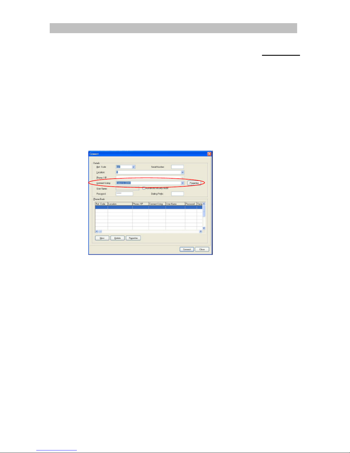
1. Prepare a Laptop with COM port which running Windows XP
2. Install provided TeleEye WX-30 software
3. Power up RX504
4. Connect RX504 to PC by using provided NULL modem cable
5. Run TeleEye WX-30
6. Click Connections > Connect
7. Click Properties, select 57600 bit rate
8. Connect to RX504 by selecting Direct COM 1 connection
2. Format Hard Disk
New Hard Disk need to be formatted before use.
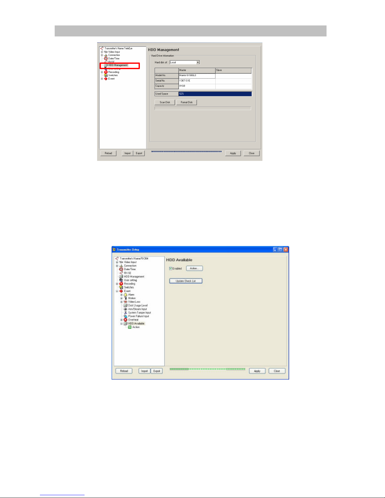
1. Click Transmitter -> Settings
2. Click [HDD Management] option on {Transmitter Setup} panel to enter {HDD
Management} panel.
Page 14
TeleEye RX504 User Guide Page 11
3. Click [Format Disk] to start format the Hard Disk.
4. RX504 will need to restart after Hard Disk format.
3. Hard Disk available event
Hard Disk available event triggers when any HDD failure or HDD changes happen. It
is recommended to enable this event after format Hard Disk. Like other events, it can
associate with dialback, E-mail and buzzer action etc.
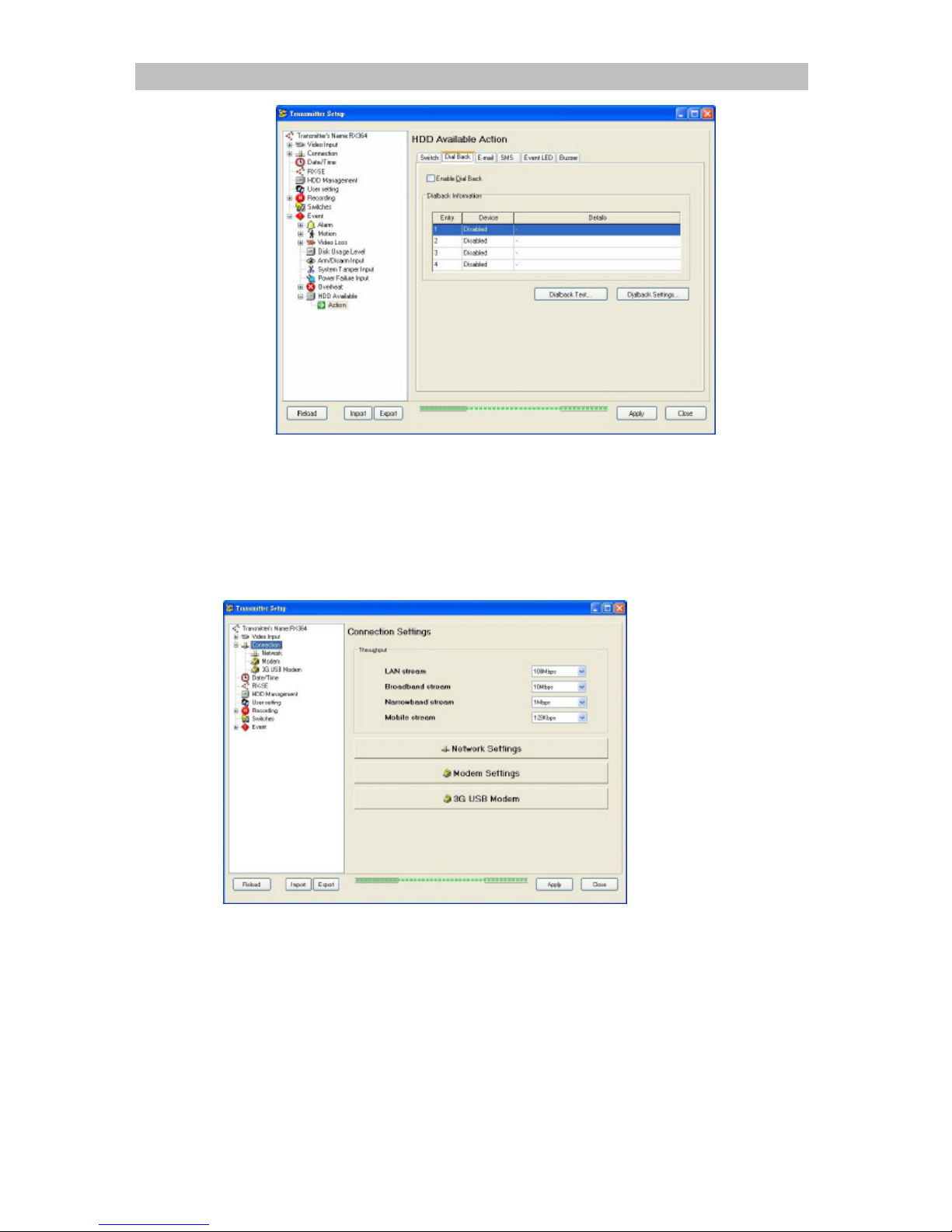
1. Click Transmitter > Settings
2. Click Event > HDD Available
3. Check Enable
4. Click Action
Page 15
TeleEye RX504 User Guide Page 12
5. Setup desired action in this panel, for details please refer to WX-30 User
manual.
6. Click [Update Check List] after change or format Hard Disk.
4. Network setup
1. Click Transmitter > Settings
2. Click Connection
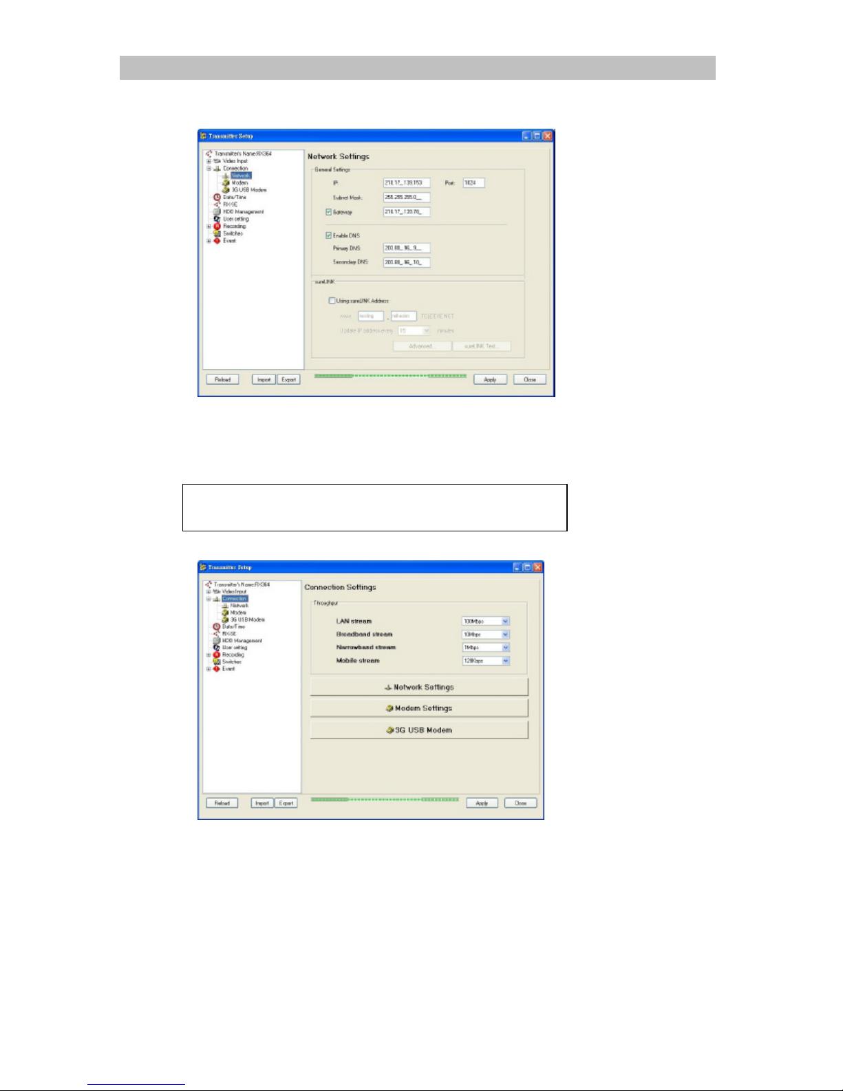
3. Throughput setting is used to limit RX504’s output data rate at individual video
stream.
4. Select 100Mbps for LAN stream
5. Narrowband throughput, following are suggested initial throughput for reference
only.
l HSDPA / UMTS: 512kbps
l EDGE: 64kbps
l GPRS: 19.2kbps
Noted that mobile data rate varies with different environment. If video delayed,
please select lower throughput.
6. Click Network Settings
Page 16
TeleEye RX504 User Guide Page 13
7. Set IP, port, subnet mask and gateway
8. DNS must be enabled for mobile connection, please enter valid DNS addresses.
5. Mobile data modem setup
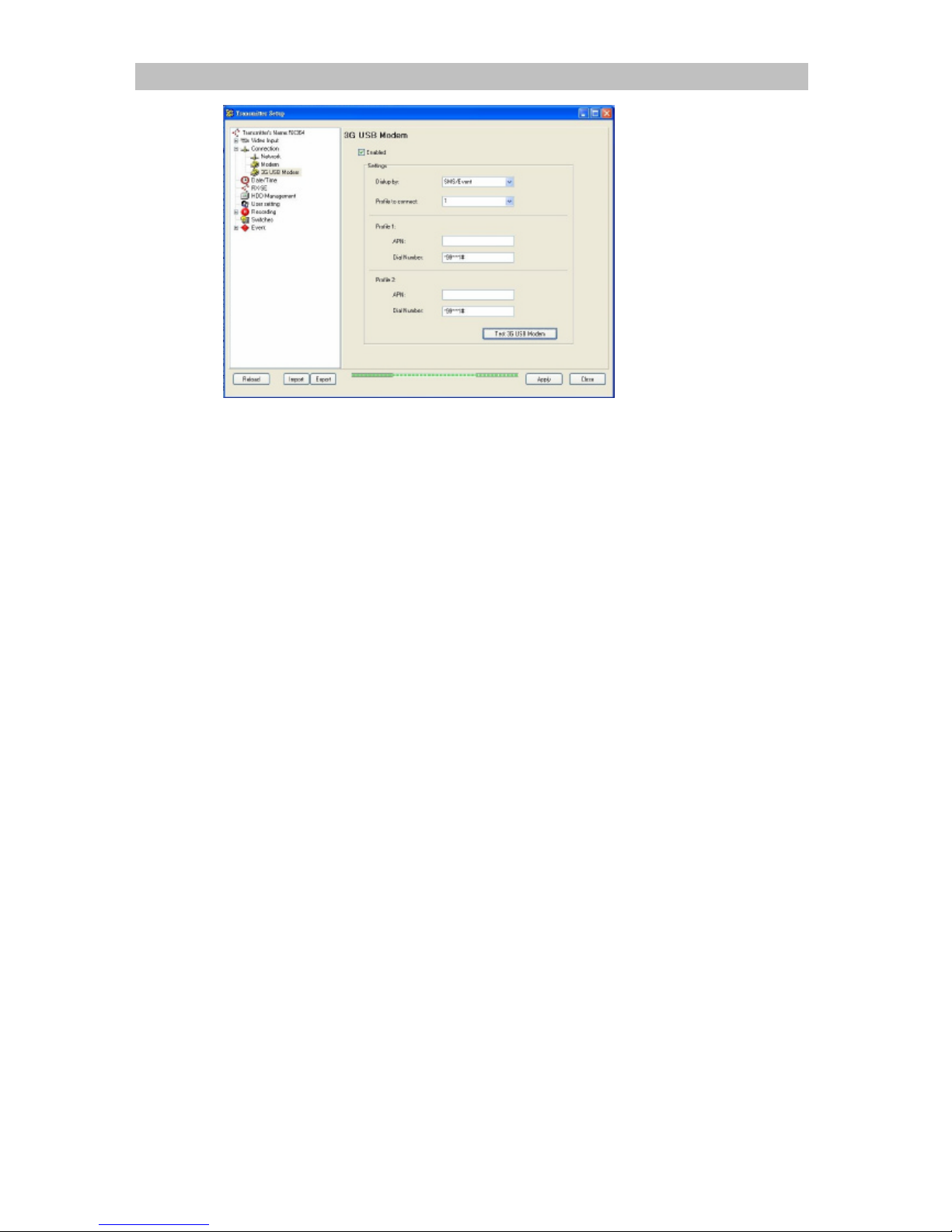
1. Click Connection Setup
2. Click 3G USB Modem
Make sure the mobile service provider support
streaming at Internet connection.
Page 17
TeleEye RX504 User Guide Page 14
3. Click enable
4. Set dialup mode: Start up and SMS / Event
1. In SMS / Event mode, RX504 will dial up to Internet only when event
trigger a dialback action or receive a valid dialback SMS message. This
mode is recommended to user who do not has real IP for mobile network
connection
2. Startup mode will dial up to Internet when RX504 power up. This mode is
only suitable for user who has real IP for mobile network connection.
5. RX504 support 2 profiles, select desired profile according to the SIM card.
6. Enter APN and dial number of the SIM card, according to telecom service
provider’s setting
7. Click Test 3G USB Modem to test the configuration
8. Click Apply to save settings
Page 18
TeleEye RX504 User Guide Page 15
Section 4
Operation
1. Live operation through mobile data modem
1. SMS / Event mode
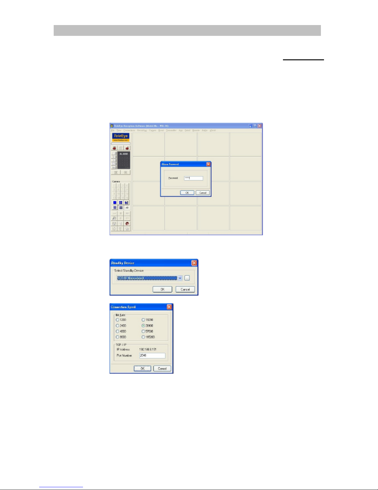
1. Run TeleEye WX-30
2. Click standby and enter password
3. Select Narrowband
4. Click … button and set listen port
5. Click OK
6. Send SMS to the SIM card’s number using the following format:
7. teip<space><dialback ip><space><port><space>endip
e.g. teip 202.73.90.90 2048 endip
8. RX504 will dialback to the given IP once received the SMS.
2. Startup mode
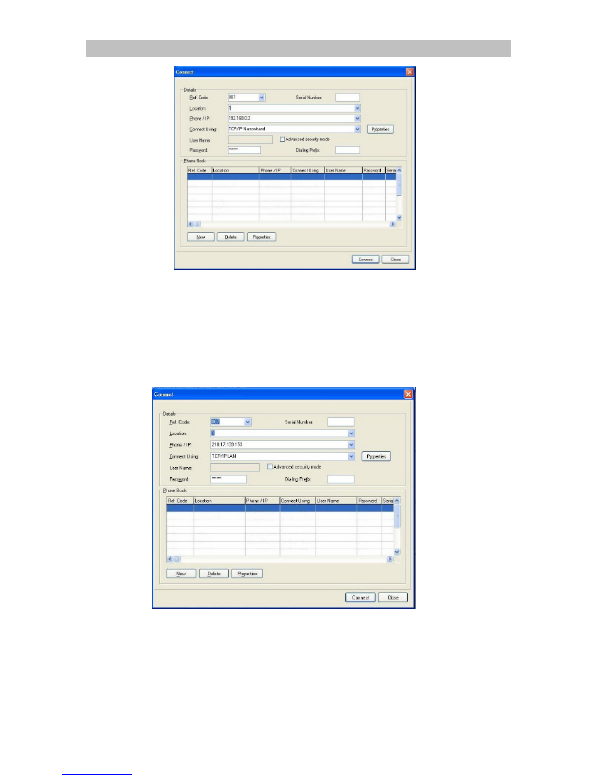
1. Run TeleEye WX-30
2. Click connect
Page 19
TeleEye RX504 User Guide Page 16
3. Enter sureLINK address or IP address
4. Select TCP/IP Narrowband
5. Enter password
6. Click Connect
2. Live operation through LAN / wireless LAN
1. Run TeleEye WX-30
2. Click connect
3. type sureLINK address or IP address
4. Select TCP/IP LAN
5. Enter password
6. Click Connect
Page 20
TeleEye RX504 User Guide Page 17
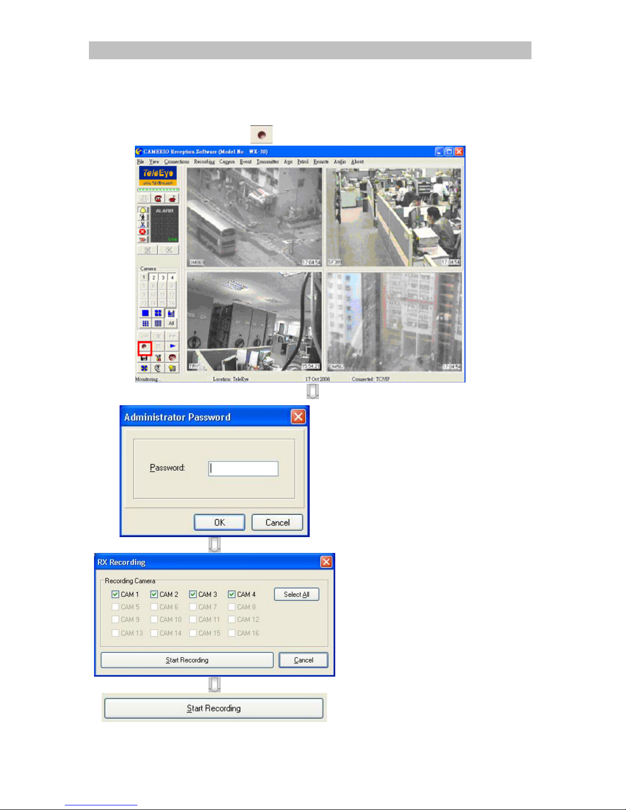
3. Recording
Manual Recording Procedure :
Step 1 : Click [Record] icon on the main panel as shown follow.
Step 2 : Enter the administrator
password.
Step 3 : {RX Recording} panel
pop up. Click the
checkbox to select the
camera for recording.
[Select All] is to select
all cameras for recording.
Step 4 : Press [Start Recording]
to start recording now.
Page 21
TeleEye RX504 User Guide Page 18
4. Video extraction
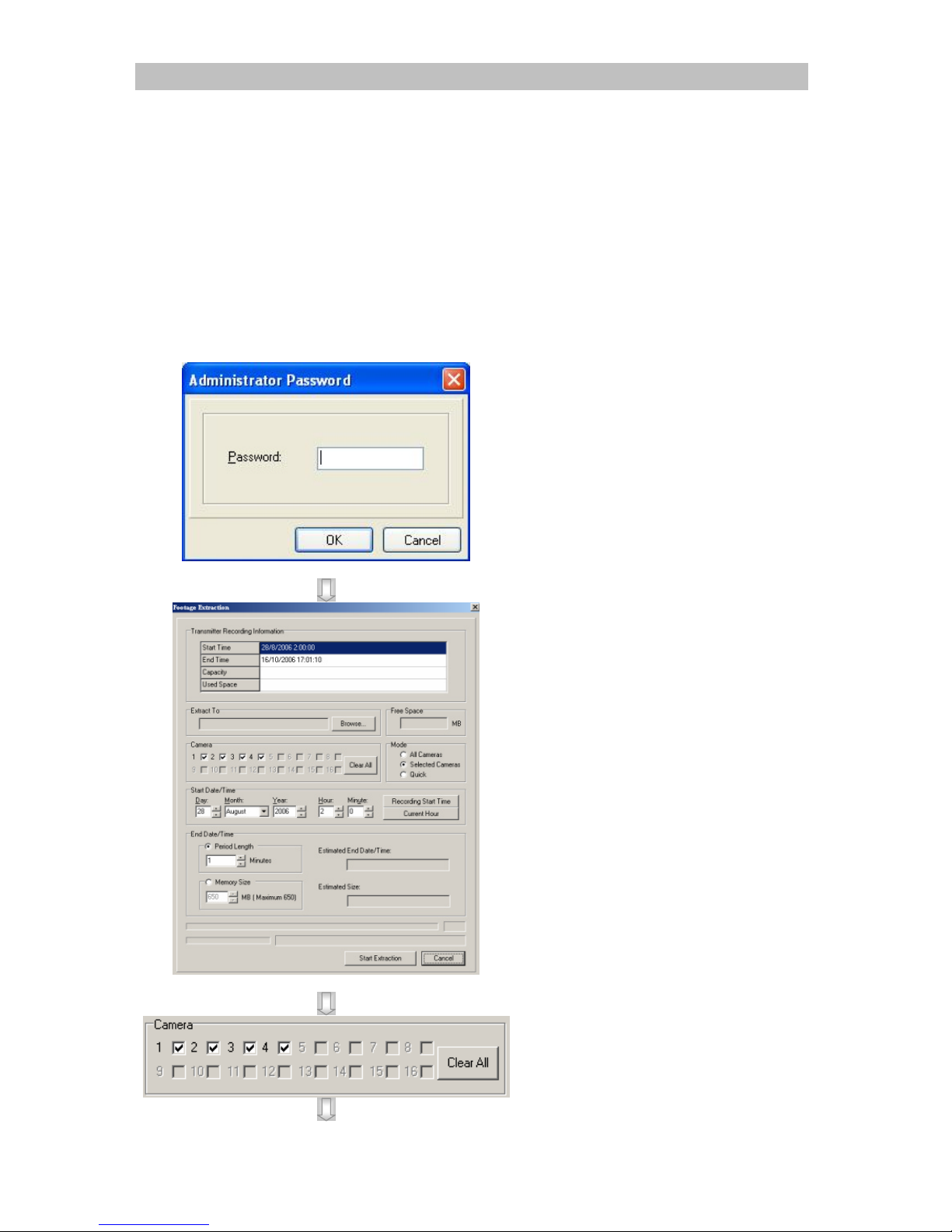
Extract footage for back up purpose. This function can back up the data stored in the
transmitter into local hard disk. User only need to select the amount of memory and
starting time for back up and the function will calculate the end time automatically.
It is recommended to use LAN / wireless LAN connection to achieve maximum
extraction speed. See Section 4.2.
Step 1: Click [Transmitter] > [Setup] > [recording]
Step 2: Click on [Footage Extraction] button
Step 3 :
{Administrator
Password} panel will
pop up. Input the
administrator password
and click [OK].
Step 4 :
{Footage Extraction}
panel will pop up. Click
[Browse…] to choose a
folder for extraction.
Step 5: In {Footage Extraction}
panel, select camera(s)
for footage extraction.
Page 22
TeleEye RX504 User Guide Page 19
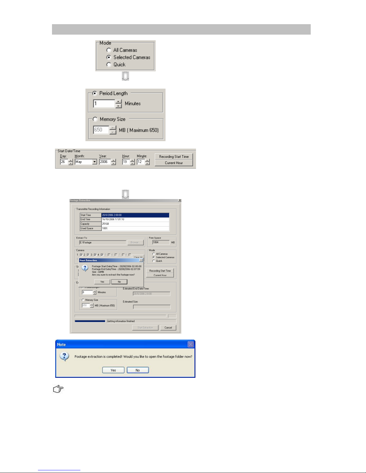
Step 6: Select mode for footage
extraction.
Note: Lower frame rate
for quick mode.
Step 7 : Input Start Date / Time
and Period Length /
Footage Size in the boxes
provided.
(Note(Optional):
1. Click [Recording
Start Time] to select
start time of the
recording log.
2. Click [Current Hour]
to select current hour of
the transmitter.)
Click [Start Extraction]
to start.
Step 8 : A {Format} panel will
pop up. Click [Yes] to
continue
Step 9 : When the extraction is
finished, {Note} will pop
up. Click [Yes] or [No]
to choose open the
footage folder or not.
Backup will not be successful if --
1. Two sites carrying out backup process in the remote site at the same time.
2. Recording retention process carrying out at the same time.
Page 23

TeleEye RX504 User Guide Page 20
Appendix 1
Limited Warranty
Conditions, Limitations and Liabilities of This Warranty:
1. Signal Communications Ltd. (hereinafter called TeleEye) provides free repairing
labour and free repairing parts for the first 12 months. Please present the Warranty
Card and the original invoice when you are asking for service support.
2. In case of applicable, TeleEye staff shall request a remote access inspection or
trouble shooting through internet, PSTN, ISDN, or mobile media.
3. When service is required, the Customer is responsible for all the transportation costs.
4. Outdoor services are not included. Subject to TeleEye, outdoor services will be
provided at extra charges.
5. This warranty does not extend to cover any damages or malfunction resulting from
disaster, environmental factor, abnormal humidity/temperature, improper voltage,
electrostatic discharge, misuse, negligence, ignorance, accident, mold, or repairs
/modifications made by any person(s) other than the authorized personnel of
TeleEye.
6. TeleEye reserves the right to charge Customer an inspection fee, on-site service fee
or cost of parts if (i) no fault in the equipment can be found during inspection or (ii)
the defect is caused at conditions those mentioned in point 5 above or (iii) Customer
fail in providing access methods to the site or the equipment, e.g. specified access
permit or key. Such determination is up to the sole discretion of TeleEye.
7. The warranty is void if any of the cabinet seal has been removed or opened if there is
any such sign not being made by any authorized personnel of TeleEye.
8. Under no circumstance shall TeleEye be liable for any damages to any parties so
caused by the usage of the above specified equipment or so caused during service
provision.
9. The conditions, limitations and liabilities of this warranty card may be extended to
further terms and conditions or superseded by other terms and conditions when
otherwise specified on any of the products.
10. Customer shall be responsible for backing up the data contained in the disk products.
11. TeleEye shall have no responsibility arising out of any damage to, or loss of the data
contained in the disk products.
12. All the above determinations are up to the sole discretion of TeleEye.
Page 24

TeleEye RX504 User Guide Page 21
Appendix 2
sureLINK Technology
sureLINK technology is available in TeleEye RX, which enables you to connect to the
TeleEye RX with broadband dynamic IP Internet connection. If you can only use broadband
dial-up account to connect to the Internet through your computer, sureLINK provides a solution
for sharing the Internet connection between your computer and the TeleEye RX.
sureLINK is a group of additional functions, services and software provided for the TeleEye
RX so as to make it connect to the Internet in any connection methods. Such function can only
be used if you have applied for this service. After you have done so, you also need to configure
the TeleEye RX to make sureLINK available. This section will help you to configure and use
it.
By using of sureLINK technology, the powerful TeleEye RX can work on broadband
Internet economically. You can perform a cost effective and convenient remote live video
monitoring anytime and anywhere.
sureLINK Address
You can apply for a sureLINK address (domain name), such as
www.hkpublic.teleeye.teleeye.net, for your TeleEye RX. You can use this name to login or
browse the built-in web server **. One of the advantages is that you are not required to
memorize the IP address (e.g. 210.177.50.156) of the TeleEye RX. Since the sureLINK
address is fixed while the IP address may change periodically (in case when dynamic IP is used),
you do not need to worry about the expiration of the IP address. The sureLINK address can also
be used in TeleEye RX web browsing to see live video on standard web browser (e.g. IE,
Netscape).
Refreshing Rate
When sureLINK address feature is enabled, the TeleEye RX will periodically update its
current IP address to our database to ensure that the sureLINK address is always forwarded to a
valid IP. You can set this update period through WX-30 software.
DNS Services:
Assigned when the TeleEye RX can directly access the Internet without the help of TeleEye
Proxy Server
Page 25
TeleEye RX504 User Guide Page 22
How to Apply for sureLINK Address
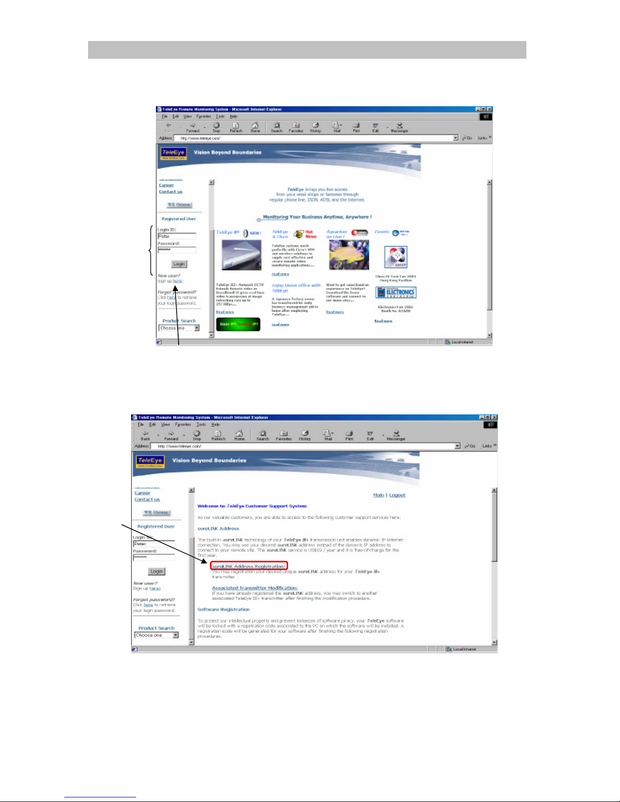
You can apply for sureLINK by visiting our web site at http://www.TeleEye.com
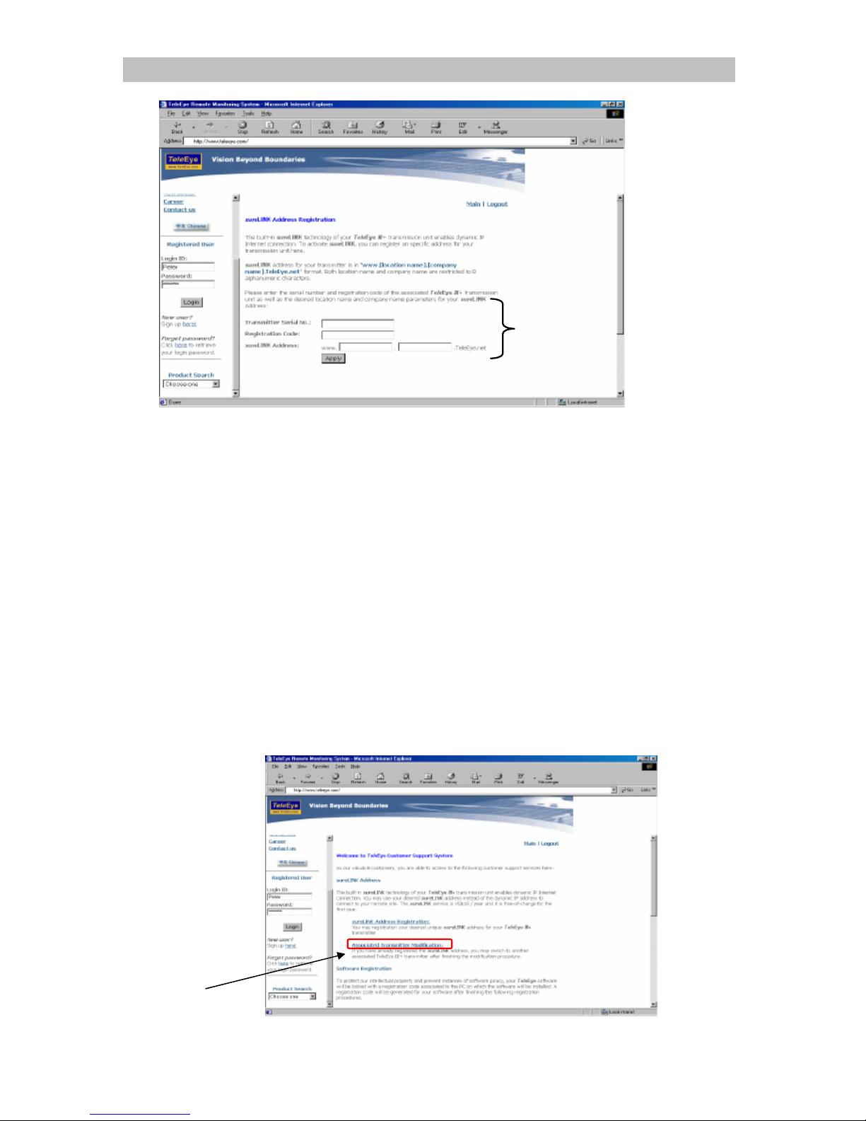
1. Sign up to create your user account
2. Login the page using your registered name and password.
3. Click sureLINK Address Registration button
Step 3
Step
Step 1
Page 26
TeleEye RX504 User Guide Page 23
4. Enter a sureLINK address (Domain Name), your TeleEye RX Serial No. and
Registration Code in the fields provided respectively. Then click the Apply button. The
process is then completed.
After we receive your domain name registration for your TeleEye RX, your application will be
processed. Normally, it requires about 2 to 3 working days to activate sureLINK for your
TeleEye RX. You will receive a notification e-mail when your sureLINK service is ready.
Video Server Modification
Since the sureLINK (Domain name) address corresponds to a single transmitter, if you change
from one transmitter to another one, you have to inform us to update our database record. To do
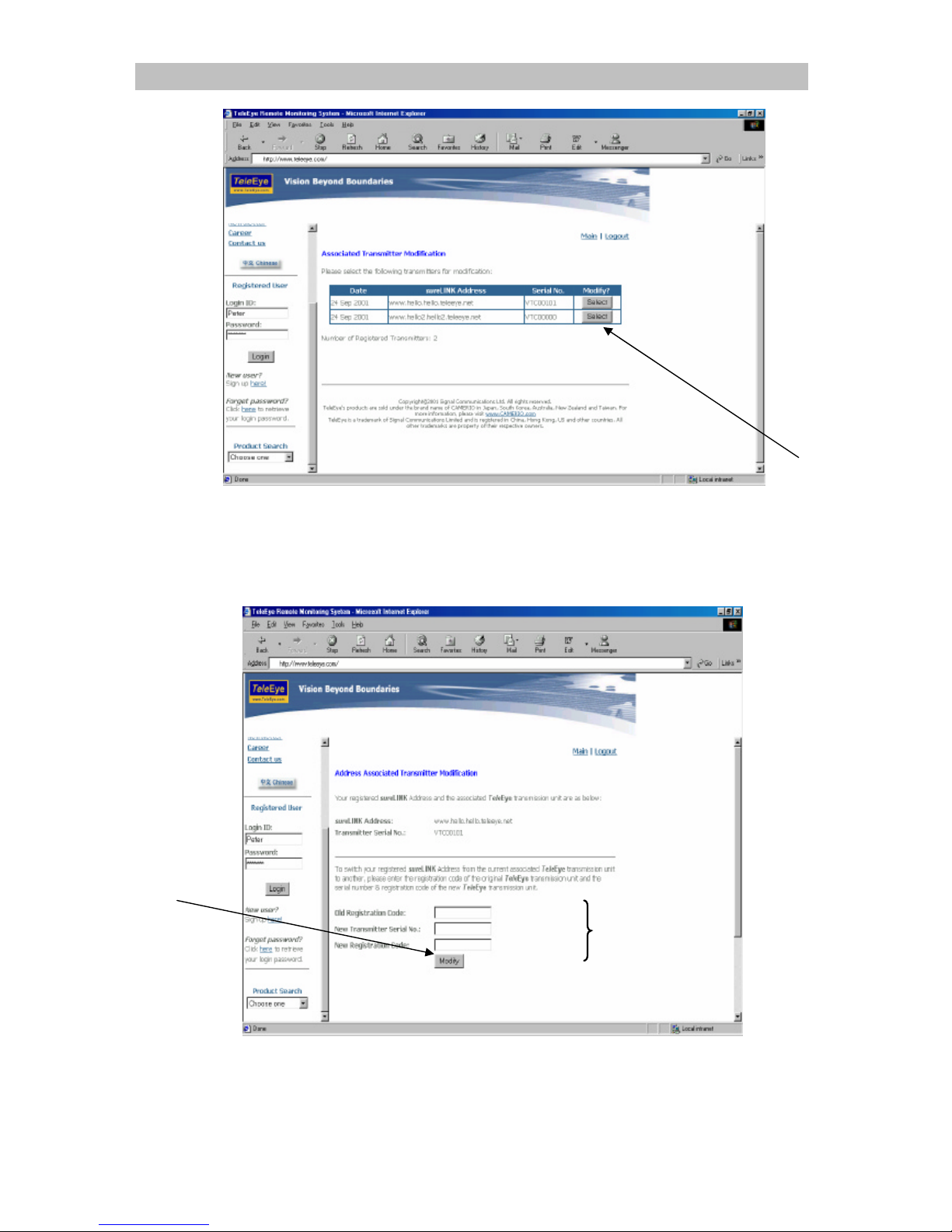
this, you can visit our TeleEye Product Support again and follow the steps as below:
1. Transmitter Modification > Select a sureLINK address (Domain Name) you want to
modify
Step 1
Step 4
Page 27
TeleEye RX504 User Guide Page 24
2. Enter the Old Registration Code, New Transmitter Serial Number and New
Registration Code at each field provided. Click Modify button to submit the form.
If the above procedure is completed successfully, the sureLINK will be effective immediately.
Step 2
Step 3
Step 4
Page 28
TeleEye RX504 User Guide Page 25
Appendix 3
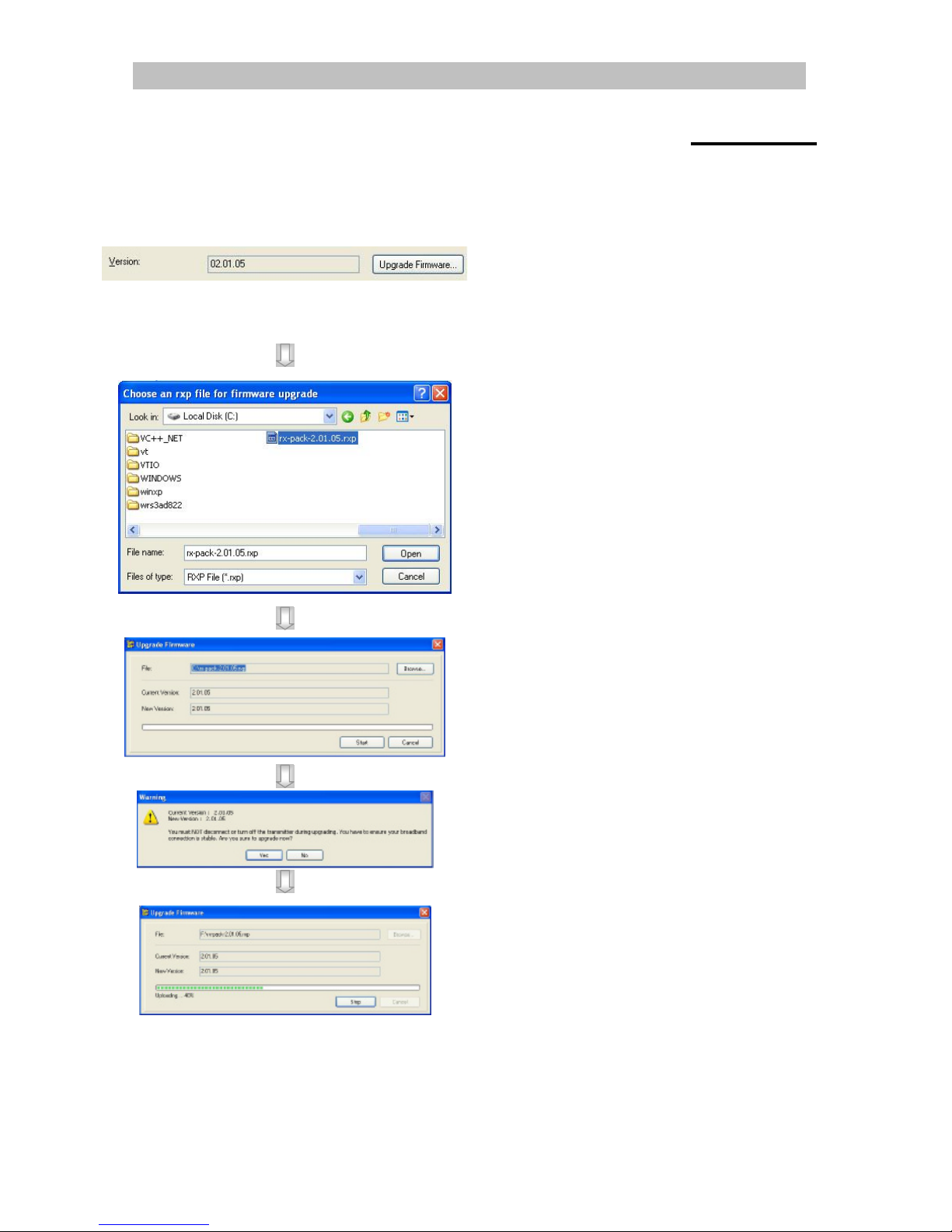
Firmware Upgrade
Step 1 : Click Transmitter -> Settings
On {Transmitter
Information} panel, click
[Upgrade Firmware]
Step 2 :
A panel [Choose an RX file
for firmware upgrade] will
pop up.
Choose the rxp file and click
[Open].
Step 3:
A panel [Upgrade
Firmware] will pop up and
click [Start] to start
upgrading.
Step 4: A warning message will pop
up, click [Yes] to continue
Step 5: Wait until the progress bar
became full.
**Do not close the panel
until upgrading finished.
Page 29
TeleEye RX504 User Guide Page 26
Appendix 4
Security Mode
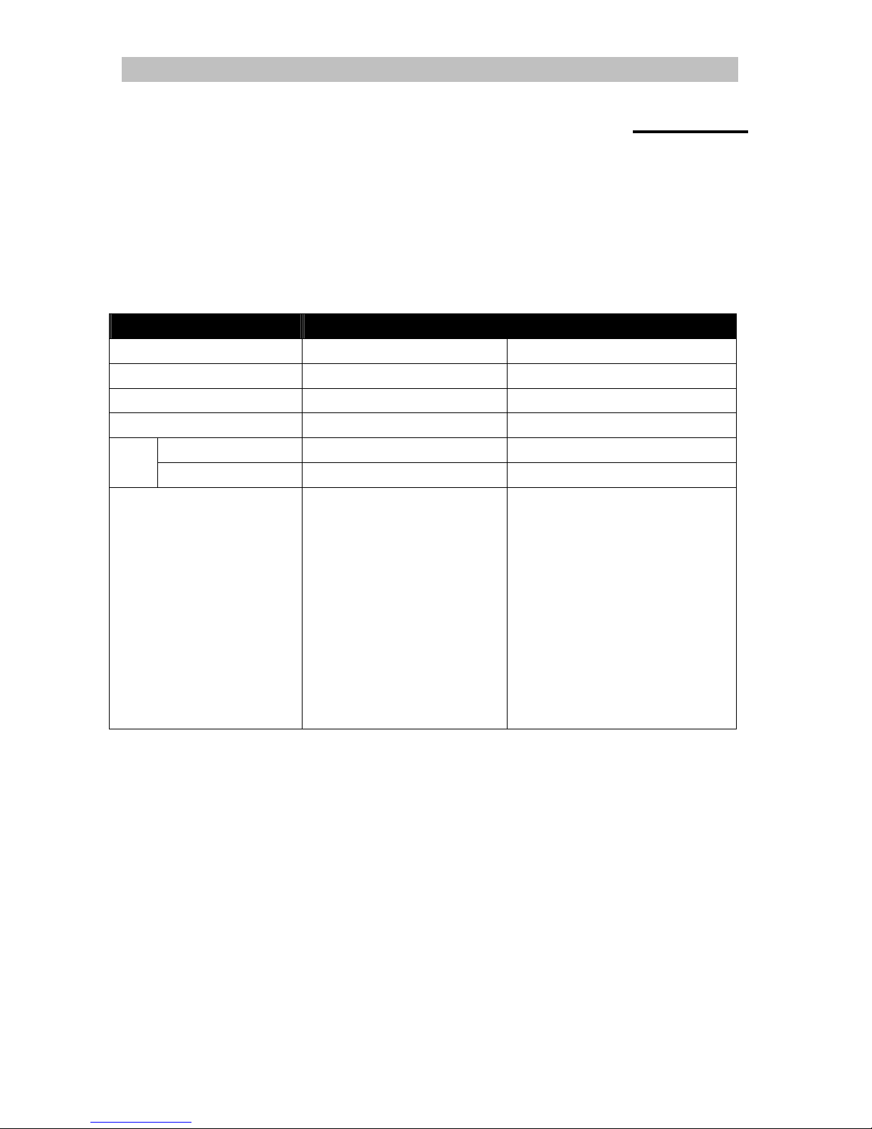
On RX504, there are 2 security modes: BASIC and ADVANCED. User can either choose
BASIC security mode for simple usage or ADVANCED security mode for multiple user
accounts and flexible access right. The comparison of the security modes can be found in the
following table:
Description Basic Security Mode Advanced Security Mode
Number of account 2 20
Account apply on reception software reception software and local OSD
Password length 6 4 – 10
Password encryption No Yes
Reception software Only password User name and password Login
Local menu - - Only password
Access right Operation
System setting
Video monitoring
Audio monitoring and PA
Playback
Camera Control
Event Control
Switch Control
Video backup
Recording
System setting
User account
l 6 concurrent users in both security modes
Page 30
TeleEye RX504 User Guide Page 27
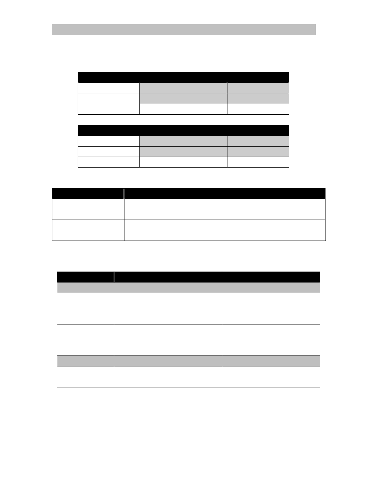
Basic security mode -- User account
ADMINISTRATOR
Type Default Remark
User name ADMINISTRATOR FIXED
Access right Operation and System setting FIXED
Network password 000000 Available to change
USER
Type Default Remark
User name USER FIXED
Access right Operation FIXED
Network password 123456 Available to change
Basic security mode -- Access right
Group Features Involved
Operation Video/audio monitoring, PTZ, Playback, Switch control
System setting Start/stop recording, Video backup, System setting, Restart transmitter
Firmware upgrade
Advanced security mode -- User account
Account structure
Type Description Remark
General setting
User name Login user name from remote
software
4-16 characters
case insensitive
unique between each account
Account type LOCAL / NETWORK / BOTH allow user to login from local
OSD / remote software / both
Access right Access right of the user account (Access right)
Network account type setting
Network password Login password from remote software 4-10 characters
case insensitive
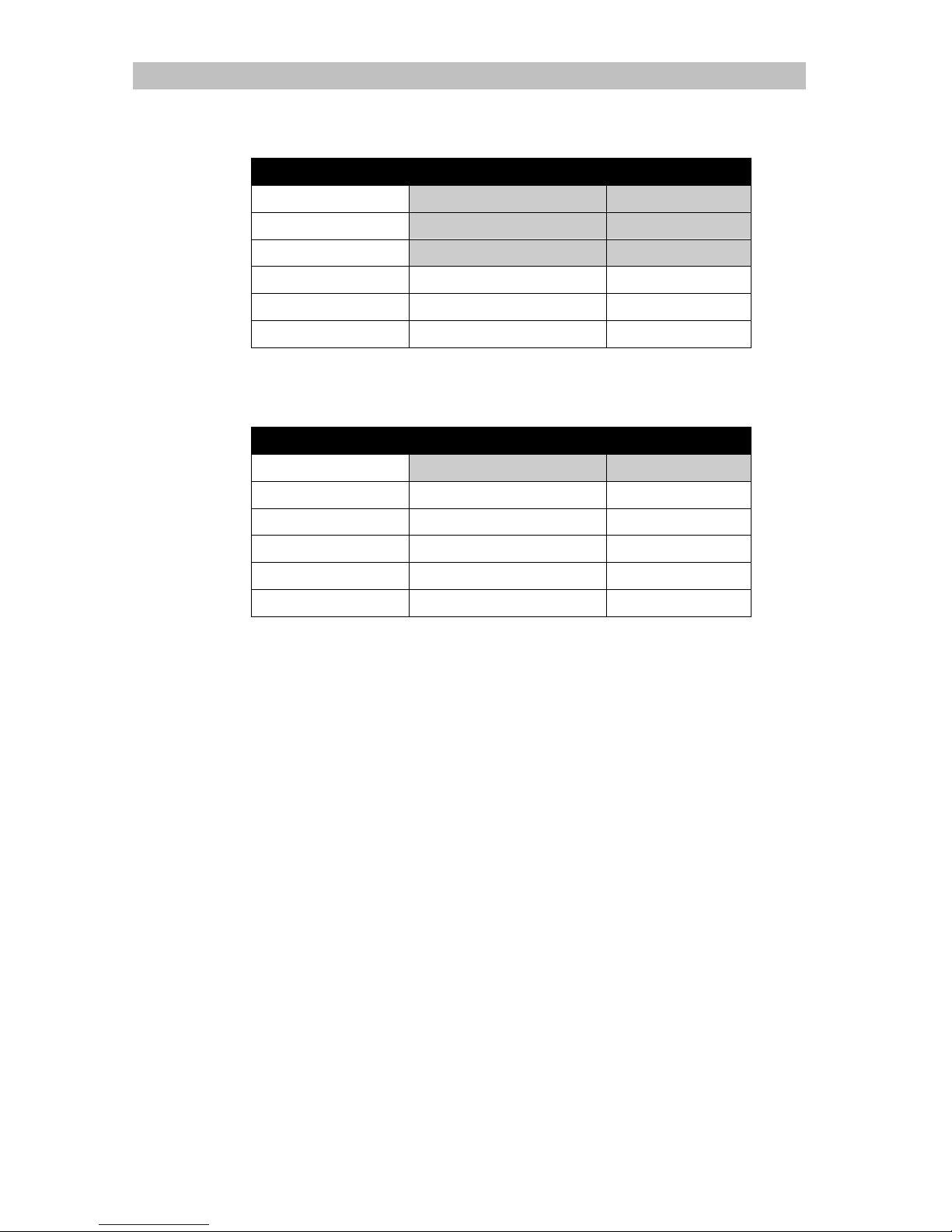
In factory default, 2 preset accounts: ADMINISTRATOR and USER1 are stored in the
transmitter.
Page 31
TeleEye RX504 User Guide Page 28
Administrator account: ADMINISTRATOR**
Type Default Remark
User name ADMINISTRATOR FIXED
Account type BOTH FIXED
Access right ALL FIXED
Network password 000000 Available to change
Local password 111111 Available to change
Local time out 15 MINS Available to change
**Administrator account cannot be removed
Normal account: USER1
Type Default Remark
User name USER1 FIXED
Account type BOTH Available to change
Access right VIDEO MONITORING Available to change
Network password 123456 Available to change
Local password 123456 Available to change
Local time out 15 MINS Available to change
Page 32

TeleEye RX504 User Guide Page 29
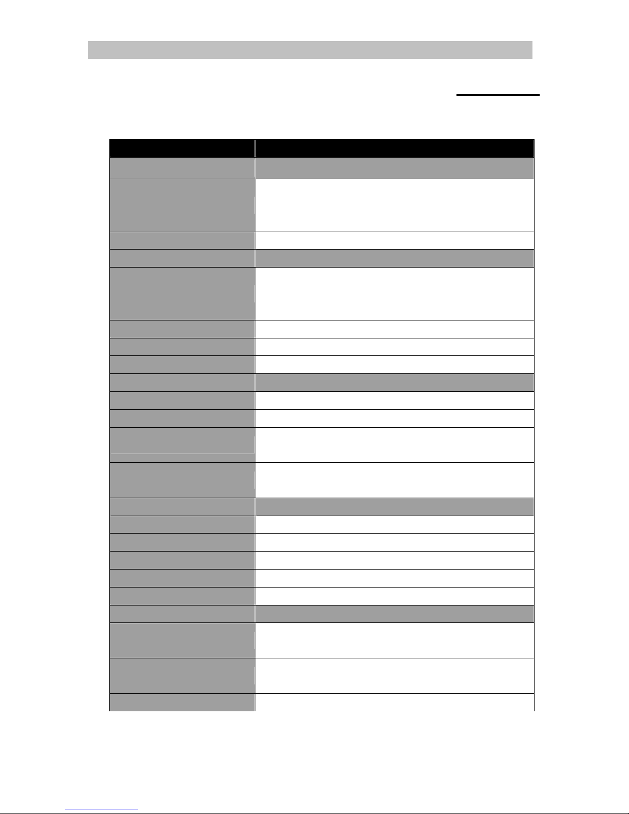
Advanced security mode -- Access right
Group Features Involved
VIDEO MONITORING
#
basic video monitoring with fixed cameras
browsing the event status**
AUDIO MONITORING
and PA
audio monitoring**
PA with microphone, PA with pre-recorded voice clips
PLAYBACK video playback**
browsing event logs , connection log, setting log and operation log
CAMERA CONTROL PTZ**
EVENT CTRL clear event
SWITCH CONTROL switch control
{All video monitoring}, {audio monitoring} & {playback} access right group will be enabled
VIDEO BACKUP1 video extraction and backup
RECORDING1 start/stop recording
start/stop schedule recording
SYSTEM SETTING1 video format, camera installation, throughput control setting
change live video quality, brightness, contrast
network and modem setting
data/time setting
hard-disk formatting
recording setting
switch setting
event setting
firmware upgrade
shutdown/restart
All access right group will be enabled
USER ACCOUNT2 setting import/export
user account setting
switch transmitter security mode
restore factory setting
# at least one camera should be selected
** Video monitoring dependence. For example, if user has no access right on camera 2
monitoring, he cannot browse event status, control PTZ and playback on this camera.
1
Automatic enable all video monitoring, audio monitoring and playback permission
2
Automatic enable all access right permission
Page 33
TeleEye RX504 User Guide Page 30
Appendix 5
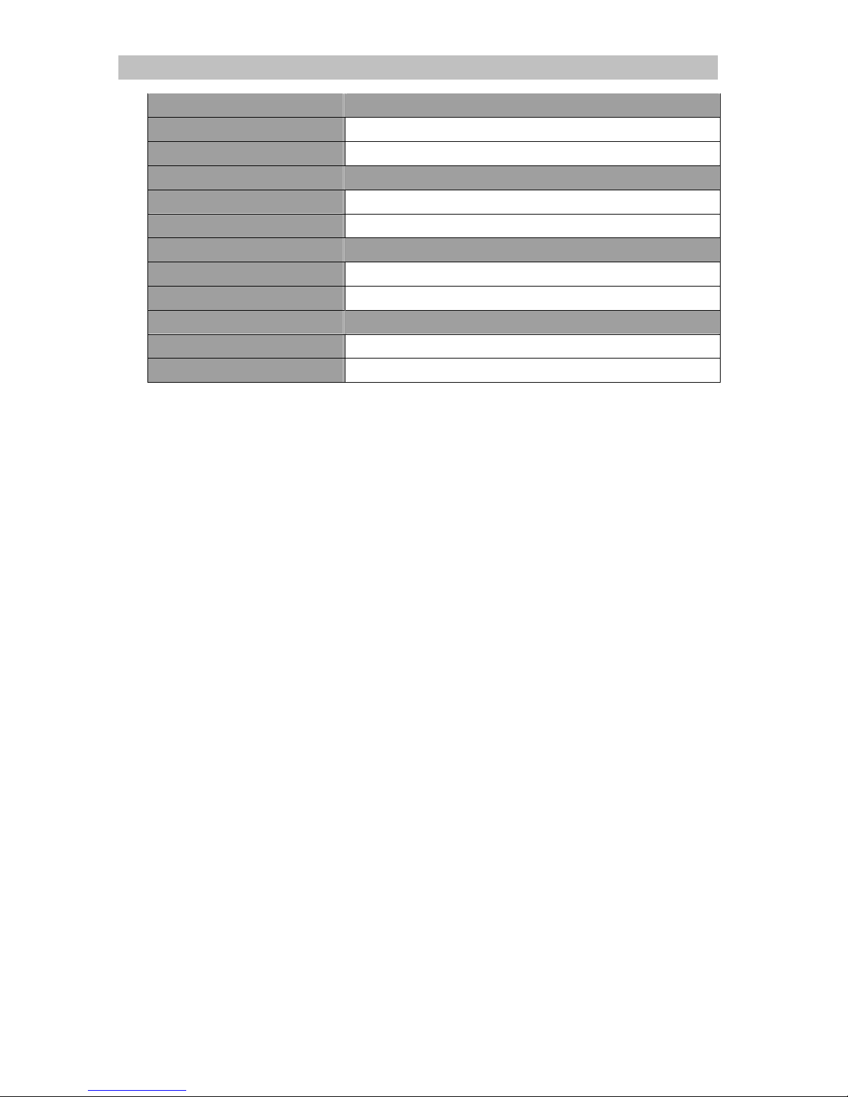
Specification
MODEL
RX504
VIDEO INPUT
STANDARD
(P): PAL/CCIR, 625 lines, 25 frames per second
(N): NTSC/EIA, 525 lines, 30 frames per second
composite video, 1 Vp-p, BNC
NO. OF CHANNELS 4
VIDEO OUTPUT
STANDARD
(P): PAL/CCIR, 625 lines, 25 frames per second
(N): NTSC/EIA, 525 lines, 30 frames per second
composite video, 1 Vp-p, BNC
NO. OF CHANNELS 1
DISPLAY SCREEN Full, Quad
DISPLAY FRAME RATE 25/30fps D1, 100/120fps CIF
RECORDING
MODE
Manual, event-driven
HD TYPE
2.5 Inch IDE interface
MAX. RECORDING RATE
(P) : 25fps at 720 X 576 pixels; 100fps at 360 X 288 pixels
(N) : 30fps at 720 X 480 pixels; 120fps at 360 X 240 pixels
PLAYBACK
Forward, Backward, Pause, Step Forward, Step Backward, x10 Fast Forward, x100 Fast
Forward
COMMUNICATION
NETWORK RJ-45, 10/100 Base-T Ethernet (auto-sensing)
MAX. TRANSMISSION FRAME RATE
25/30fps D1, 50/60fps CIF
VIDEO COMPRESSION SMAC-M
USB
USB 2.0, 12Mbps
WIRELESS COMMUNICATION
HSDPA, UMTS, EDGE, GPRS, IEEE 802.11b / 802.11g
EVENT HANDLING
EVENT TYPE
External alarm, tamper, video motion detection, video loss,
disk full, power interruption, system fail, disk usage, overheat
ACTION TYPE
Live camera, buzzer, dial back, recording,
relay control, PTZ, email notification, SMS
EXTERNAL ALARM INPUTS
16 x NC/NO
Page 34
TeleEye RX504 User Guide Page 31
RELAY SWITCH
NO. OF CHANNELS
4
MAX. RATING
24V AC, 1000mA
POWER
VOLTAGE
10-24V DC (12V typical)
MAX. RATING
15W
OPERATING ENVIRONMENT
AMBIENT TEMPERATURE
5°C - 40°C
RELATIVE HUMIDITY
< 85% (no condensation)
MECHANICAL DESIGN
DIMENSION
295mm (L) x 227mm(W) x 100mm (H)
NET WEIGHT
2.68kg
 Loading...