


GX Series
HD Digital Video Recorder
GX684 / GX689 / GX6816
User Guide

Contents
1.Introduction...............................................................................................................................1
1.1. Package Contents.............................................................................................................2
1.2.Functional Features............................................................................................................3
1.3. Convention Used in This Manual.......................................................................................3
1.4. Hardware Feature..............................................................................................................4
1.4.1. Front View.............................................................................................................4
1.4.2. Back View.............................................................................................................5
2. Hard Disk Installation, Formatting and Scanning................................................................7
2.1. Hard Disk Installation.........................................................................................................7
2.2. Hard Disk Formatting.......................................................................................................10
2.3. Hard Disk Scanning.........................................................................................................10
3. Setup for Local and Remote Monitoring.............................................................................11
3.1. Setup for Local VGA Monitor...........................................................................................11
3.2. Setup for LAN Connection...............................................................................................12
3.3. Setup for Broadband Internet Connection.......................................................................16
4. Local Operation.....................................................................................................................20
4.1. Icons Description.............................................................................................................20
4.2. OSD Menu.......................................................................................................................21
4.2.1. OSD Menu Operation.........................................................................................21
4.2.2. OSD Menu Structure..........................................................................................23
4.3. Basic Operation...............................................................................................................65
4.3.1. View Live Video...................................................................................................65
4.3.2. Recording............................................................................................................66
4.3.3. Playback..............................................................................................................69
4.3.4. PTZ.....................................................................................................................70
4.4. Advanced Operation........................................................................................................73
4.4.1. Install Alarm Sensors and Relay Control Port.....................................................73
4.4.2. Install Tamper Circuit and External Resistors.....................................................73
4.4.3. Event Handling....................................................................................................76
4.4.3.1. Arm/Disarm.............................................................................................76
4.4.3.2. Security Switch.......................................................................................80
4.4.3.3. Alarm.......................................................................................................81
4.4.3.4. Motion.....................................................................................................88
4.4.3.5. Video Loss..............................................................................................89
4.4.3.6. System Tamper.......................................................................................90
4.4.3.7. Power Failure..........................................................................................91
4.4.3.8. Disk Usage.............................................................................................92

4.4.3.9. HDD Fault...............................................................................................92
4.4.3.10. System Restart.....................................................................................92
4.4.4. Event Action........................................................................................................93
4.4.4.1.Recording ...............................................................................................93
4.4.4.2. Switch.....................................................................................................94
4.4.4.3.Dialback...................................................................................................95
4.4.4.4. E-mail......................................................................................................96
4.4.4.5. SMS .......................................................................................................97
4.4.4.6. Buzzer ....................................................................................................97
4.4.4.7. Event LED...............................................................................................97
4.4.4.8. Live Camera...........................................................................................98
4.4.4.8. PTZ.........................................................................................................98
4.4.5. Footage Extraction.............................................................................................99
4.4.6. Throughput Control..........................................................................................100
4.4.7. Switch Control..................................................................................................101
4.4.8. Time Synchronization.......................................................................................101
4.4.9. Import and Export.............................................................................................103
4.4.10. User Account..................................................................................................104
4.4.11. SMS................................................................................................................107
5. Remote Operation...............................................................................................................108
5.1. Remote Operation.........................................................................................................108
5.1.1. Port Mapping Setup..........................................................................................108
5.1.2. sureLINK Setup................................................................................................108
5.2. Icons Description...........................................................................................................109
5.3.Basic Operation...............................................................................................................111
5.3.1. View Live Video.................................................................................................111
5.3.2. Recording..........................................................................................................113
5.3.3. Playback............................................................................................................115
5.4.Advanced Operation.......................................................................................................116
5.4.1. Hard Disk Formatting........................................................................................116
5.4.2. Hard Disk Scanning...........................................................................................116
5.4.3. Hard Disk Turn On/Off.......................................................................................116
5.4.4. Event Handling..................................................................................................117
5.4.4.1. Arm/Disarm...........................................................................................117
5.4.4.2. Alarm.....................................................................................................119
5.4.4.3. Motion...................................................................................................120
5.4.4.4. Video Loss............................................................................................121
5.4.4.5. System Tamper.....................................................................................122

5.4.4.6. Power Failure........................................................................................122
5.4.4.7. Disk Usage...........................................................................................123
5.4.4.8. Disk Fault..............................................................................................123
5.4.4.9. System Restart.....................................................................................124
5.4.5. Event Action......................................................................................................124
5.4.5.1. Recording.............................................................................................125
5.4.5.2. Switch...................................................................................................125
5.4.5.3. Dialback................................................................................................126
5.4.5.4. E-mail....................................................................................................127
5.4.5.5. SMS......................................................................................................127
5.4.5.6. Buzzer ..................................................................................................128
5.4.5.7. Event LED.............................................................................................128
5.4.5.8. Live Camera.........................................................................................128
5.4.5.9. PTZ.......................................................................................................129
5.4.6. Pan Tilt Zoom....................................................................................................129
5.4.7. Footage Extraction............................................................................................132
5.4.8. Throughput Control...........................................................................................132
5.4.9. Switch Control...................................................................................................133
5.4.10. Time Synchronization......................................................................................134
5.4.11. Import and Export............................................................................................135
5.4.12. User Account...................................................................................................136
5.4.13. Maintenance Log Backup...............................................................................137
Appendix A: Safety Instruction..............................................................................................138
Appendix B: Limited Warranty...............................................................................................139
Appendix C: sureLINK Technology........................................................................................140
Appendix D: Firmware Upgrade.............................................................................................145
Appendix E: Security Mode....................................................................................................146
Appendix F: General Terms Discussion................................................................................149
Appendix G: Audit Trail Log Description..............................................................................150
Appendix H: Specification......................................................................................................154

Notice:
Signal Communications Limited reserves the right to make improvements to the product
described in this manual at any time and without notice.
This manual is copyrighted. All rights are reserved. This manual should not be copied,
reproduced or translated in whole or part without prior consent from Signal
Communications Limited.
TeleEye is a trademark of Signal Communications Limited and is registered in China,
European Communities, Hong Kong, US and other countries.
All other trademarks are the property of their respective owners.
Copyright (c) 2015 Signal Communications Limited (A member of TeleEye Group). All
rights reserved.
Version 1.00
Limits of Liability and Disclaimer of Warranty
Signal Communications Limited has taken care in preparation of this manual, but makes
no expressed or implied warranty of any kind and assume no responsibility for errors or
omissions. No liability is assumed for incidental or consequential damages in connection
with or arising out of the use of the information or accessories contained herein.
Features and specifications are subject to change without prior notice.

User Guide PAGE 1
Section 1: Introduction
TeleEye GX680 is a range of HD digital video recorders, which is specially designed for
dedicated and shared network architecture. All GX models support real-time HD recording
up to the maximum frame rate of 480 fps.
TeleEye GX680 provides faster transmission and longer recording utilizing our proprietary
HD SMAC-M compression technology. HD SMAC-M compresses video with 50% smaller
in size compared to H.264*, leading to faster transmission and requires less storage. Its
multi-stream architecture generates 4 independent data streams to assure optimized video
recording and transmission performance across different environments.
TeleEye GX680 has developed special video streaming protocols that provide extra
security during Internet transmission. The 5 protection layers incorporated in the TeleEye
video surveillance solutions are able to shield off hacker's attacks via the Internet.
TeleEye GX680 Series HD digital video recorder works with TeleEye cameras and third
party ONVIF Profile S cameras, providing extra protection on the video data for safer
transmission across any public networks.
**Data quote from : Secutech Camera Excellence Award 2011 ;Compression rate depends
on actual scene under measurement and different results maybe obtained due to motion
or scene changes.

User Guide PAGE 2
1.1. Package Contents
Make sure the following items are included within the package.
5. Mouse
6. Power Adaptor
3. Registration
code sheet
10. HDD
screws
11. Straight-through
Ethernet cable
2. Warranty
card
9. Software CD
7. Resistors
(for tamper
detection)
1. TeleEye GX HD digital
video recorder
8. Alarm port
connector & alarm port
cover
4. HDD recommendation
sheet

User Guide PAGE 3
1.2. Functional Features
•
Independent & efficient HD recording stream
•
1080p/720p HDTV resolution
•
Support TeleEye MX, MP and NX series, IP cameras conform to ONVIF profile S
•
Video recording up to 400/480 fps
•
Configurable recording frame rate
•
Supporting up to 4 SATA HDDs
•
USB video extraction
•
Flexible connections: LAN, broadband & mobile network
•
Support both static & dynamic IP
•
Independent video network: require only one IP for up to 16 MX HD Video Cameras
•
IP filtering
•
Single point video throughput control
•
Mobile video monitoring
•
Triplex operation: simultaneous video monitoring, recording & playback
•
HD video output
•
Multiple login accounts
•
Compliance with BS 8418
•
Sophisticated event management
•
Multi-language OSD
•
Mouse control
1.3. Convention Used in This Manual
[ ] Menu or buttons in On Screen Display (OSD) menu or software
“ “ Option in On Screen Display (OSD) menu or software
Remarks

User Guide PAGE 4
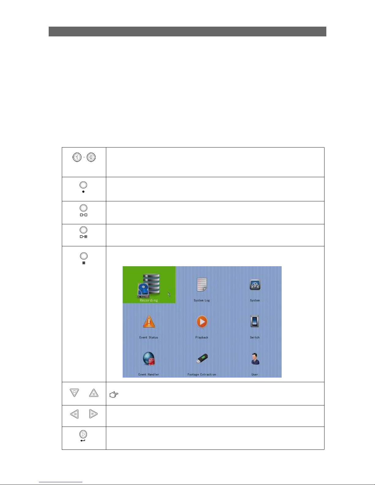
1.4. Hardware Feature
1.4.1. Front View
1. Notification LEDs
LED Description
Light up when power on
Light up when performing recording
Blink when an event is triggered
2. Main control buttons
Button Description
Select camera /
Enter password
Quick button for recording
Display next cameras /
Start sequential mode
Change to next screen
mode
(e.g. Full Quad)
Open main OSD menu /
Back to previous menu
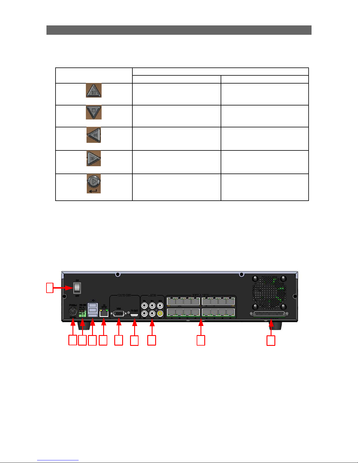
User Guide PAGE 5
3. Menu control / local playback control buttons
Button Description
Menu mode Playback mode
Up Pause
Down Stop
Left Rewind
Right Forward
Enter Play
4. Front USB port
For mouse control, firmware upgrade, footage extraction, setting import/export
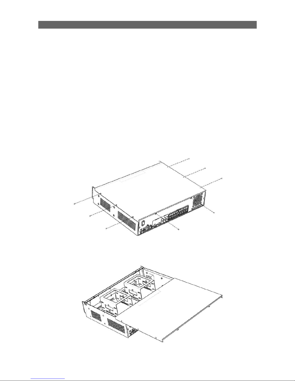
1.4.2. Back View
1. Power switch
•
Switch on or off the TeleEye GX HD Digital Video Recorder
2. Power input (16V DC)
•
Power supply to TeleEye GX
1
2
3
4
5
6
7
8
9
10

User Guide PAGE 6
3. RS-485 in/out port
•
In : 2-way terminal block for connecting a keyboard controller to control a PTZ
camera
•
Out : 2-way terminal block for connecting a PTZ camera
4. Rear USB port
•
For mouse control, firmware upgrade, footage extraction, setting import/export
5. Ethernet jack (10/100/1000 Base-T)
•
Connect to the corporate computer network (e.g. LAN)
6. VGA output
•
Standard VGA connector
7. TV output
•
HDTV output connector
8. Audio in/out port, PA
•
Audio In : Connect to audio input device (e.g. amplified microphone) for
recording
•
Audio Out : Connect to audio output device (e.g. amplified speaker) to generate
output audio signal
•
Audio PA : Connect to audio output device (e.g. amplified speaker) to facilitate
remote public addressing
9. Digital video input ports
•
RJ-45 connectors for video source input
10.Alarm/switch port
•
16 alarm inputs: NC/NO type and none/SEOL/DEOL tamper type
•
4 special inputs: Arm/disarm, security switch, system tamper, power failure
•
4 relay outputs: Latching or push-button type
User Guide PAGE 7
Section 2: Hard Disk Installation,
Formatting and Scanning
2.1. Hard Disk Installation
Hard disk is required in recording, video playback and keeping different types of log.
Follow the steps below for disk installation. A hard disk recommendation list has been
included in the package as a reference.
1. Make sure that the digital video recorder is turned off.
2. Loosen the screws that hold the cover.
3. Pull off the cover.

User Guide PAGE 8
4. Loosen the screws of the hard disk holder.
5. Insert HDD into one of the available holders. Maximum 4 HDD can be installed.
6. Mount the HDD to the holder with attached screws.

User Guide PAGE 9
7. Remount the hard disk holder to TeleEye GX.
8. Connect the SATA cable to the HDD.

User Guide PAGE 10
2.2. Hard Disk Formatting
Formatting is required when the format of an installed hard disk cannot be recognized by
the digital video recorder, most likely a hard disk that has not been used by the video
server. Another purpose of disk formatting is to clean up recording space and redeem the
file allocation.
An unrecognized hard disk will be formatted automatically after TeleEye GX starts up.
Formatting will erase all data inside the disk. Hence make sure that important data has
been backed up before performing this function. Once it is reconstructed, it would be
readable and writable by the digital video recorder.
User can also perform disk formatting manually. The function can be found in the OSD
menu: [Main Menu] [HDD/Recording] [Disk Management]
Format: Format the selected hard disk
Format All: Format all installed hard disks
2.3. Hard Disk Scanning
Hard disk scanning is a maintenance function similar to the Scan Disk function provided by
the operating system of a personal computer. This function is provided in an attempt to
rescue the hard disk in case errors are found, and to enhance its performance and
reliability. The function can be found in the OSD menu:
[Main Menu] [HDD/Recording] [Disk Management]. Clicking on the
[Scan All] button will start scanning all installed hard disk.

User Guide PAGE 11
Section 3: Setup for Local and
Remote Monitoring
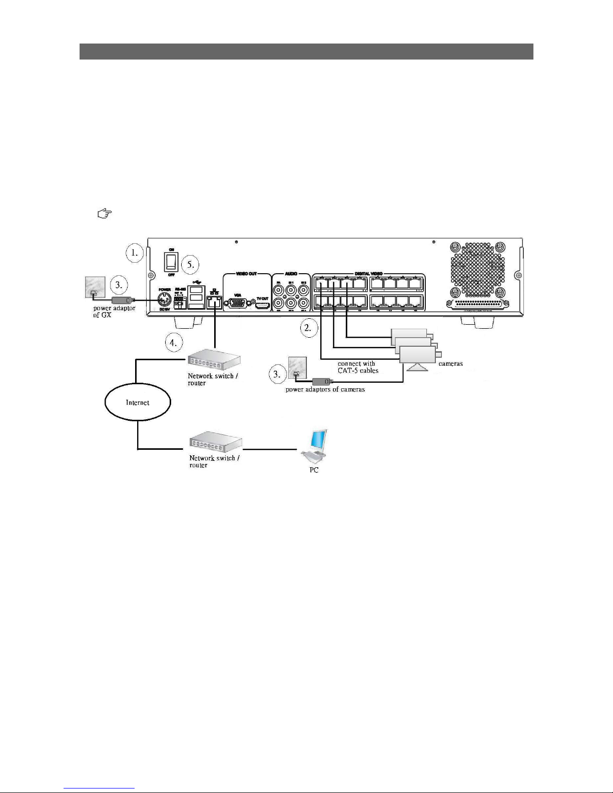
3.1. Setup for Local VGA Monitor
Equipment:
•
TeleEye GX HD Digital Video Recorder and its power adaptor
•
Cameras and their power adaptors
•
CAT-5 cable
•
VGA / TV monitor
•
VGA / HDTV cable
Setup Procedures:
1. Install a hard disk to the TeleEye GX
If there is no hard disk installed, Recording and Playback are not functional
2. Connect cameras to the video ports of TeleEye GX
3. Connect a monitor to the VGA output of TeleEye GX
4. Plug in the power adaptors to TeleEye GX, cameras and monitors.

User Guide PAGE 12
5. Switch on the power of TeleEye GX. A startup screen will appear on the connected
monitor.
6. If all installed hard disks are not in TeleEye GX recognized format, they would be
formatted automatically when startup completes.
7. TeleEye GX is ready for operation. Live video should appear on the monitor. By default,
manual recording will be started automatically.
3.2. Setup for LAN Connection
Equipment:
•
TeleEye GX HD Digital Video Recorder and its power adaptor
•
Cameras and their power adaptors
•
CAT-5 cable
•
Network switch or router
•
PC

User Guide PAGE 13
PC Requirements:
•
CPU : Intel ® Core i3 Processor
•
RAM : 2 GB
•
HDD : 10 GB free space
•
Display : Direct 3D, Nvidia GeForce GT 220 / ATI Radeon HD 5450 or above
•
OS : Windows XP, Windows Vista or Windows 7
Other Requirements:
•
Java : Sun Microsystems Java 2 runtime Version 1.5.0 or above
•
IE : Windows Internet Explorer Version 6 or above
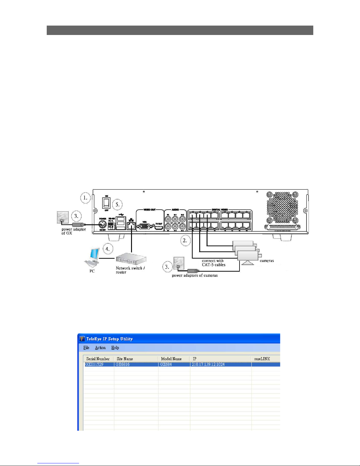
Setup Procedures on GX Side:
1. Install a hard disk to the TeleEye GX
If there is no hard disk installed, Recording and Playback are not functional
2. Connect cameras to the video ports of TeleEye GX
3. Plug in the power adaptors to TeleEye GX and cameras.
4. Connect TeleEye GX to the network switch.
5. Switch on the power switch of TeleEye GX.
6. If all installed hard disks are not in TeleEye GX recognized format, they would be
formatted automatically when startup completes.
Setup Procedures on PC Side:
1. Install TeleEye IP Setup Utility. .NET framework is also needed for the operations. Both
can be found in the included software CD.
User Guide PAGE 14
2. Run IP Setup Utility.
3. Find the TeleEye GX according to the serial number provided by the provider.
4. By default, TeleEye GX obtains the IP address, netmask and gateway automatically
through DHCP. To assign a static value, deselect the “Obtain an IP address
automatically” checkbox and enter the corresponding information. The gateway should
be the IP address of the router.
The DNS setting is used for sureLINK, time synchronization and e-mail notification.
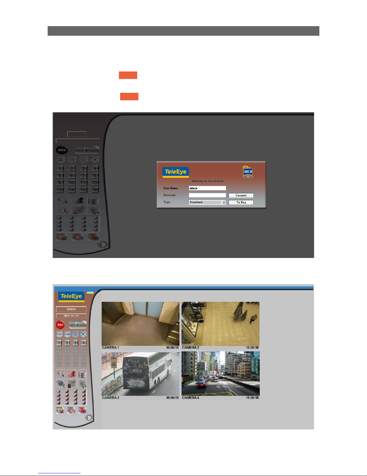
5. To access the TeleEye GX, double click the row representing the digital video recorder.
A web browser should be opened automatically.
The first 3 fields of IP address of the PC should be the same as that of TeleEye
GX.
6. Besides accessing through IP Setup Utility, user can also open a web browser and type
the IP address plus port number in the format http://IPAddress:PortNumber (e.g.
http://192.168.0.12:1024) or sureLINK address in address bar directly.

User Guide PAGE 15
7. By default, user name is “admin”. Enter password and press [Connect].
(The default administrator password is “0”+“digits of serial number”. There is an
example:
Serial Number :GXS11529
User Name : admin
Default Password : 011529
Details can be found in the registration code sheet)
8. Live video is shown after successful connection.

User Guide PAGE 16
3.3. Setup for Broadband Internet Connection
Equipment:
•
TeleEye GX HD Digital Video Recorder and its power adaptor
•
Cameras and their power adaptors
•
CAT-5 cable
•
Network switch or router
•
PC
PC Requirements:
•
CPU: Intel ® Core i3 Processor
•
RAM: 2 GB
•
HDD: 10 GB free space
•
Display:Direct 3D, Nvidia GeForce GT 220 / ATI Radeon HD 5450 or above
•
OS: Windows XP, Windows Vista or Windows 7
Other Requirements:
•
Java: Sun Microsystems Java 2 runtime Version 1.5.0 or above
•
IE: Windows Internet Explorer Version 6 or above
Setup Procedures on GX Side:
1. Install a hard disk to the TeleEye GX
If there is no hard disk installed, Recording and Playback are not functional
User Guide PAGE 17
2. Connect cameras to the video ports of TeleEye GX.
3. Plug in the power adaptors to TeleEye GX and cameras.
4. Connect TeleEye GX to the network switch.
5. Switch on the power of TeleEye GX.
6. If all installed hard disks are not in TeleEye GX recognized format, they would be
formatted automatically when startup completes.
Setup Procedures on PC Side:
1. Configure the network settings of TeleEye GX through PC with LAN connection.
2. Install TeleEye IP Setup Utility. .NET framework is also needed for the operations. Both
can be found in the included software CD.
3. Run IP Setup Utility.
User Guide PAGE 18
4. Find the TeleEye GX according to the serial number provided by the provider.
5. By default, TeleEye GX obtains the IP address, netmask and gateway automatically
through DHCP. To assign a static value, deselect the “Obtain an IP address
automatically” checkbox and enter the corresponding information. The gateway should
be the IP address of the router.
The DNS setting is used for sureLINK, time synchronization and e-mail notification.
6. Reconnect the digital video recorder to the Internet network.
7. Configure other network settings for TeleEye GX and the PC if necessary, such as
router port mapping, firewall, etc. Please refer to the manual of the router.
8. Open a web browser and type the IP address plus port number in the format
http://IPAddress:PortNumber (e.g. http://192.168.0.12:1024) or sureLINK address in
address bar directly.
User Guide PAGE 19
9. By default, user name is “admin”. Enter password and press [Connect]. (The default
administrator password is “0”+“digits of serial number”. There is an example:
Serial Number :GXS11529
User Name : admin
Default Password : 011529
Details can be found in the registration code sheet)
10.Live video is shown after successful connection.

User Guide PAGE 20
Section 4: Local Operation
4.1. Icons Description
When observing video from local monitor, icons may be shown on the screen. Each of the
icons has its special meaning. A summary of their meanings can be found in the following
table.
Icon Representation Icon Representation
Tamper event
Arm/disarm control
Alarm event
Security switch control
Motion event Recording
Video loss event Playback
Power failure event Pause in playback
Disk usage alert event Fast Forward in playback
HDD fault event Backward in playback
Audio enabled Digital /Analog PTZ
control
PTZ tite up PTZ tite down
PTZ pan left PTZ pan right
PTZ function (only for
analog PTZ)
PTZ command subtract
(only for analog PTZ)
PTZ command add
(only for analog PTZ)
PTZ command up (only
for analog PTZ)
PTZ command down
(only for analog PTZ)
OSD object selection
PTZ command box
(only for analog PTZ)
Disk scanning
Disk formatting Recovering recording
User Guide PAGE 21
4.2. OSD Menu
Most local operations are controlled through the on screen display (OSD) menu. A detail
explanation on its operation and structure will be given in this section.
4.2.1. OSD Menu Operation
User can connect a mouse to the USB port or use the control buttons on the front panel to
perform different operations.
A. By Front Panel Buttons
Press button 1 to 9 to select Camera 1 to 9.
Press button 0 first, then press button 0 to 6 to select Camera 10 to
16.
Quick button to change recording to on, off or schedule.
Display next page of cameras (e.g. Cam 2, Cam 3).
Hold down the button for a few seconds to start sequential mode.
Switch to next screen mode (e.g. Full 2x2).
Menu button: used to open and close main OSD menu, or navigate
backward to previous menu.
Select a menu item.
Selected item will be highlighted.
Select a value for the menu option.
Enter a sub-menu.
Confirm the selection.

User Guide PAGE 22
B. By Mouse
(Left click)
Enter a sub-menu.
Select a value for menu option.
Double click on a recording log to select playback cameras.
Double click on a system log to perform searching.
Double click on an IP filtering entry to edit.
(Right click)
Used to open and close the OSD menu, or navigate backward to
previous menu.
When getting through the OSD, user will see different types of item. Their properties are
listed below:
Item Name Description
Yes/No box: 2 options only
Click on it to toggle the option
Spin box: 3 or more options available
Click on the arrows to choose another option
Drop down box: Multiple options available
Click on it to show all available options
Click on an option to select it
Edit box: Require user to enter a value
Click on it to prompt a virtual keypad for
inputting
Link: Click on it to enter a sub-menu
Tick box Click on it to toggle the option
User Guide PAGE 23
4.2.2. OSD Menu Structure
Local operations are performed through the OSD Menu. The menu architecture and brief
description on each option will be given in this section.
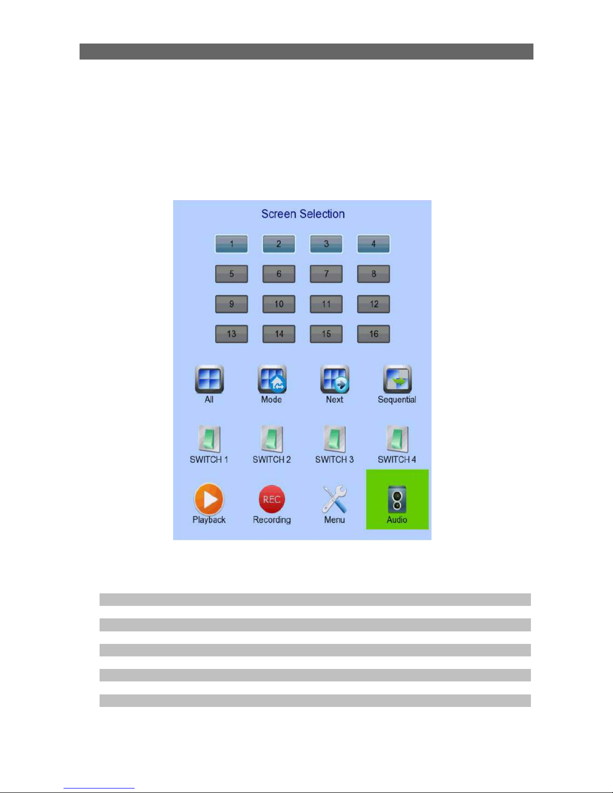
[Screen Selection]
This menu is for mouse operations and can only be opened by right clicking the mouse.
Camera Selection Panel Show currently displaying cameras
Click to display selected camera in full screen
All Display all cameras
Mode Select the display mode
Next Display next camera
Sequential Start sequential mode
Switch 1 – Switch 4 Toggle the status of the switch
Playback Display recording log
Recording Change recording to on, off or schedule
OSD Menu Open main OSD menu
Audio Select audio channel
User Guide PAGE 24
[Screen Selection] [Recording]
Recording Quick menu for selecting recording mode
•
Off :Disable recording
•
On :Enable recording of all cameras
•
Schedule :Enable schedule recording
[Main Menu]
HDD/Recording Change recording and hard disk settings
System Log Display event, connection, operation and setting log
System View server information
Change system settings (e.g. IP, date time, language)
Event Status Display event status
Clear event status
Playback Display recording log
Start video playback
Switch Control the switches
Change switch settings
Event Handler Change event settings
Footage Extraction Extract recorded video to USB flash device
User Change security mode
Change user settings
User Guide PAGE 25
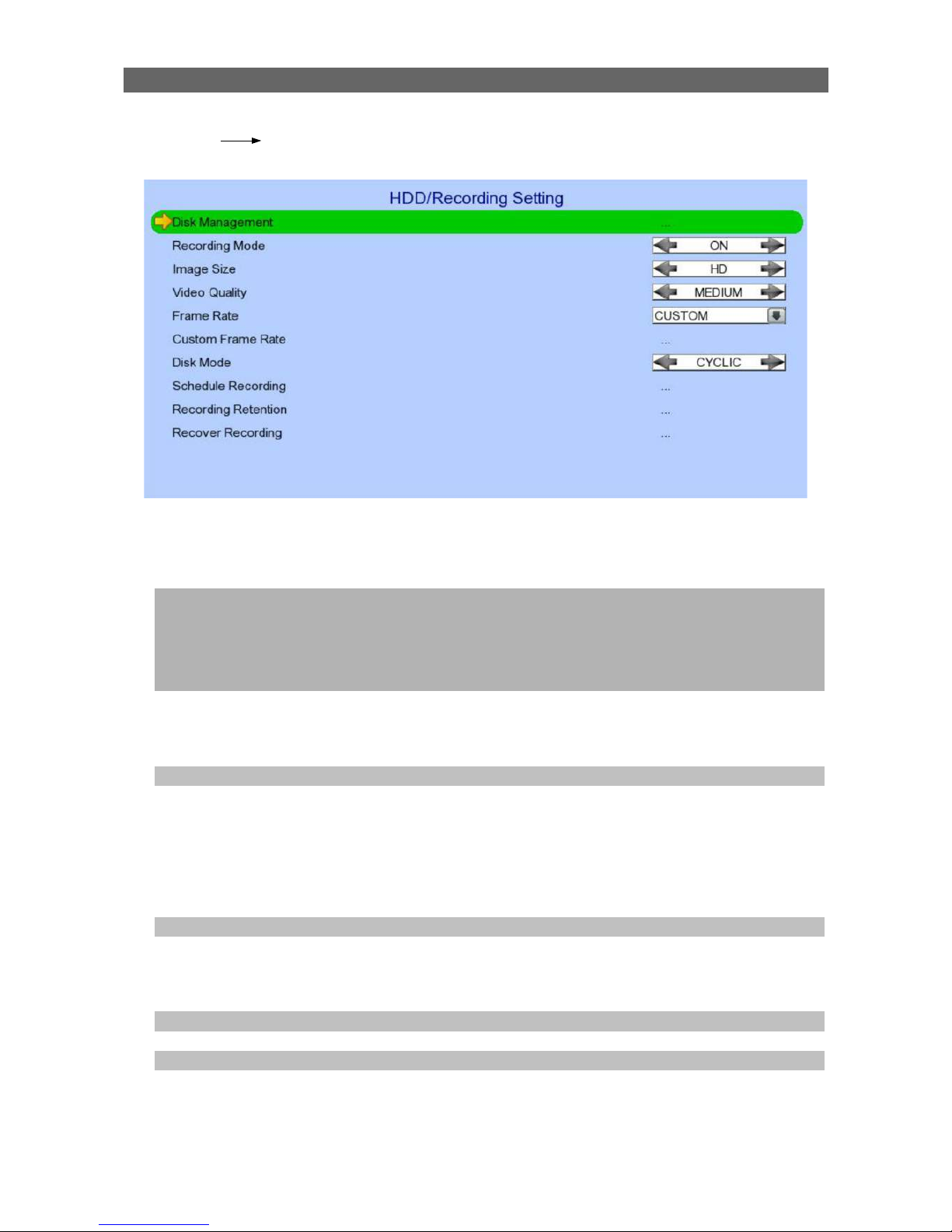
[Main Menu] [HDD/Recording]
Disk Management View hard disk information
Format, scan or turn on/off disk
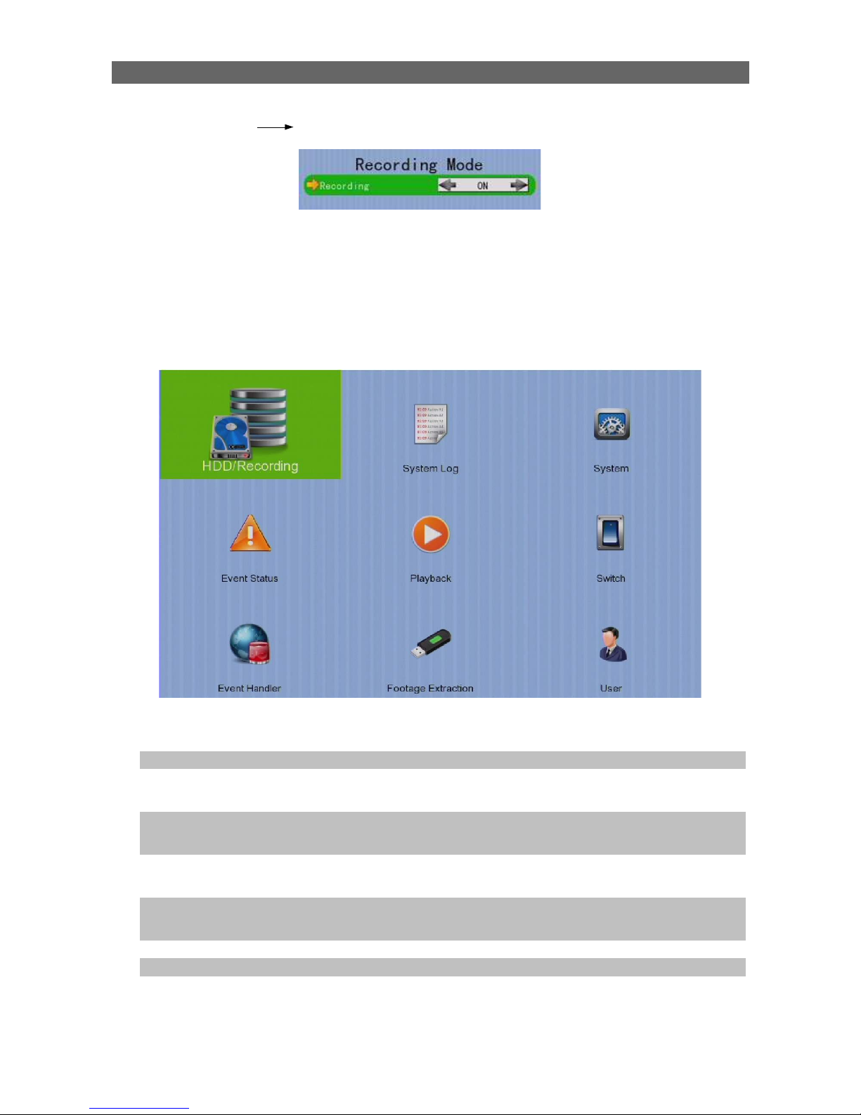
Recording Mode Select recording mode
•
Off :Disable recording
•
On :Enable recording of all cameras
•
Schedule :Enable schedule recording
Image Size Set recording resolution
•
HD :1920x1080 or 1280x720
•
QHD :640x360
Video Quality Set video quality
Frame Rate Set recording frame rate, applied to all cameras
•
Auto :Record at highest achievable frame rate
•
1 fps :Record at 1 frames per second
•
Custom :Enable custom frame rate for individual
camera
Custom Frame Rate Set recording frame rate of individual cameras
Disk Mode Set disk mode
•
Cyclic :Remove oldest data when hard disk full
•
Fixed :Stop recording when hard disk full
Schedule Recording View or change recording schedules
Recording Retention Set recording retention settings
Recover Recording Recover damaged recorded video

User Guide PAGE 26
[Main Menu] [HDD/Recording] [Disk Management]
Format Format the selected hard disk *
Turn on/off Turn on hard disk for recording purpose *
Scan All Scan all installed hard disks *
Format All Format all installed hard disks *
*
For execution, a local password of current user is required in advanced mode
[Main Menu] [HDD/Recording] [Schedule Recording]
Add
Add a new recording schedule
Edit Edit the selected schedule
Delete Delete selected schedule
Delete Day Delete all schedules of a day as the selected schedule

User Guide PAGE 27
[Main Menu] [HDD/Recording] [Schedule Recording] [Add]
Weekdays Select the weekdays to apply the schedule
Start Time Set the start time of the schedule
End Time Set the end time of the schedule
Camera Select the cameras to apply the schedule
Frame Rate Set recording frame rate of the schedule
(not applicable for Custom frame rate)
Recording Type Type of recording schedule
•
Normal :Record when within schedule
•
Motion :Record when motion detected and
within schedule
•
Custom :Record based on individual camera
setting
ADD Confirm add the schedule setting
Motion Setting Set motion detection settings
[Main Menu] [HDD/Recording] [Schedule Recording] [EDIT]
Most settings are the same as [Add] menu.
EDIT Confirm EDIT the schedule setting
User Guide PAGE 28
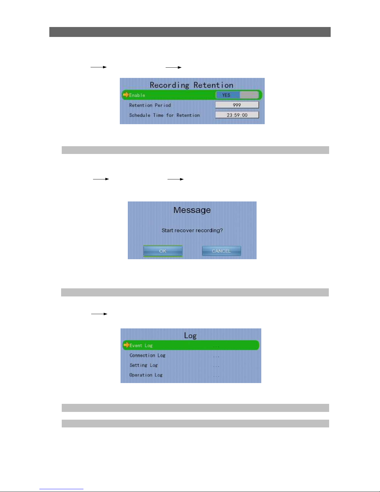
[Main Menu] [HDD/Recording] [Recording Retention]
Enable Enable / disable recording retention
Retention Period Remove recorded video after selected days
Schedule Time for Retention Remove recorded video at selected time
[Main Menu] [HDD/Recording] [Recording Recording]
Press “MENU” button can hide or display progress bar during recovering.
OK Start recover (local password of current user is required
in advanced mode )
CANCEL Back to previous page
[Main Menu] [System Log]
Event Log Display event log
Connection Log Display remote connection log
Setting Log Display setting log
Operation Log Display operation log

User Guide PAGE 29
[Main Menu] [System Log] [Event Log]
Date/Time Show event date and time
Ch Show event channel number
Status Show event status
•
Trigger :Event triggered
•
Reset :Event reset
•
Tamper :Event tampered
•
Arm :System armed
•
Disarm :System disarmed
•
Secu Switch On :Security switch turned on
•
Secu Switch Off :Security switch turned off
•
Entry :Event trigger within entry delay
•
Exit :Event trigger within exit delay
Action Show event associated actions
Show previous / next page of log
Show different types of event log

User Guide PAGE 30
[Main Menu] [System Log] [Connection Log]
Date/Time Show connection date and time
Access Show IP of the remote host
Status Show connection status
Remark Show type of connection
•
Dial in :Triggered by user
•
Dial back :Triggered by dialback action
User Show the user connected to video server through remote
software
Show previous / next page of log
User Guide PAGE 31
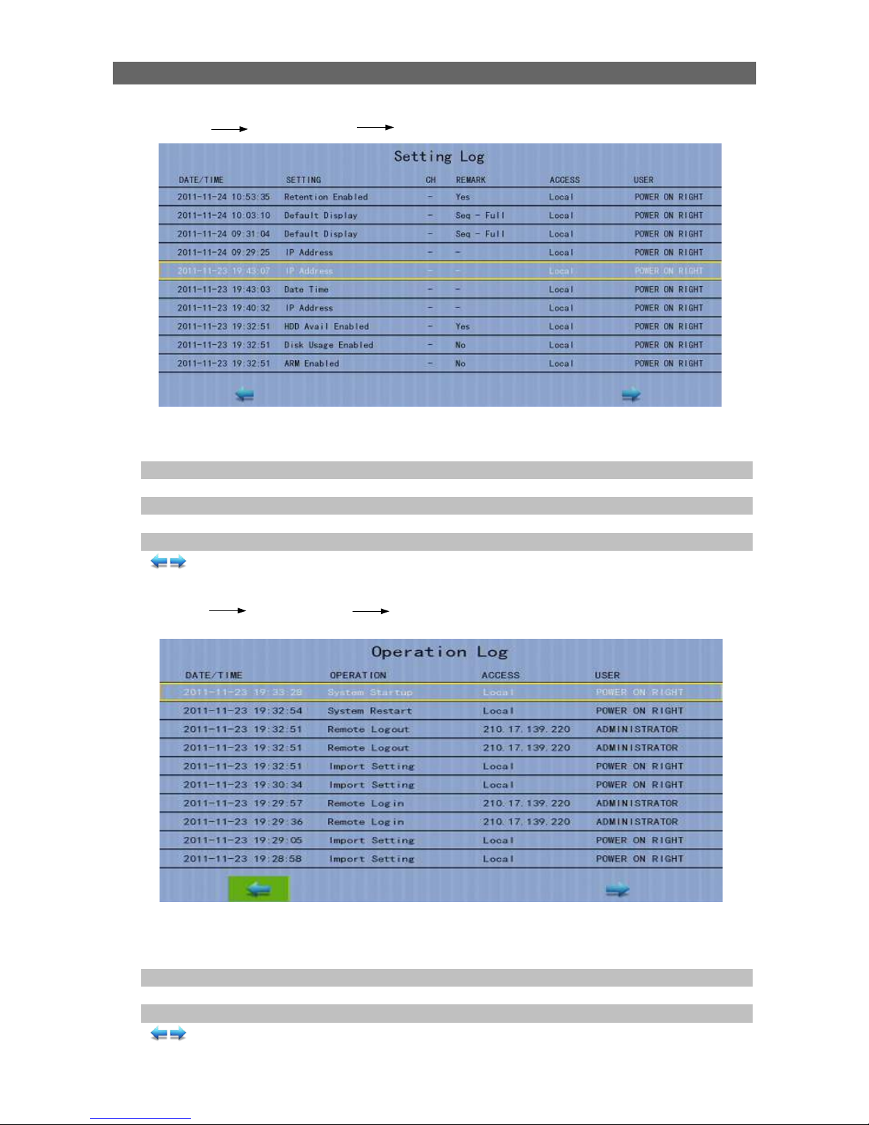
[Main Menu] [System Log] [Setting Log]
Date/Time Show date and time of the change
Setting Show setting that is changed
Ch Show channel number of setting if available
Remark Show new value of the setting
Access Show IP of the remote host or “Local” for local host
User Show the user performed the change
Show previous / next page of log
[Main Menu] [System Log] [Operation Log]
Date/Time Show date and time of the operation
Operation Show operation that is done
Access Show IP of the remote host or “Local” for local host
User Show the user performed the operation
Show previous / next page of log
User Guide PAGE 32
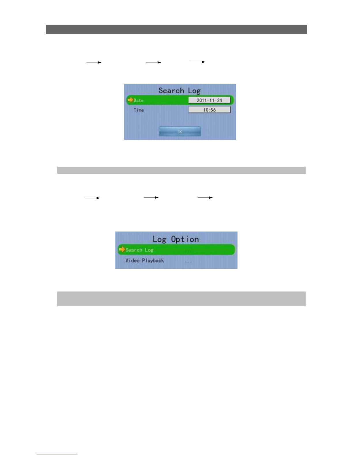
[Main Menu] [System Log] Any Log [Search Log]
Press enter or double click on any log entry to enter [Search Log] menu.
Date Set the search date
Time Set the search time
OK Search for log closest to the date and time
[Main Menu] [System Log] [Event Log] [Log Option]
If an event log entry is associated with the recording action, pressing enter or double
clicking will enter [Log Option] menu.
Search Log Enter [Search Log] menu
Video Playback Enter [Recording Log] menu with date and time of event
log
User Guide PAGE 33
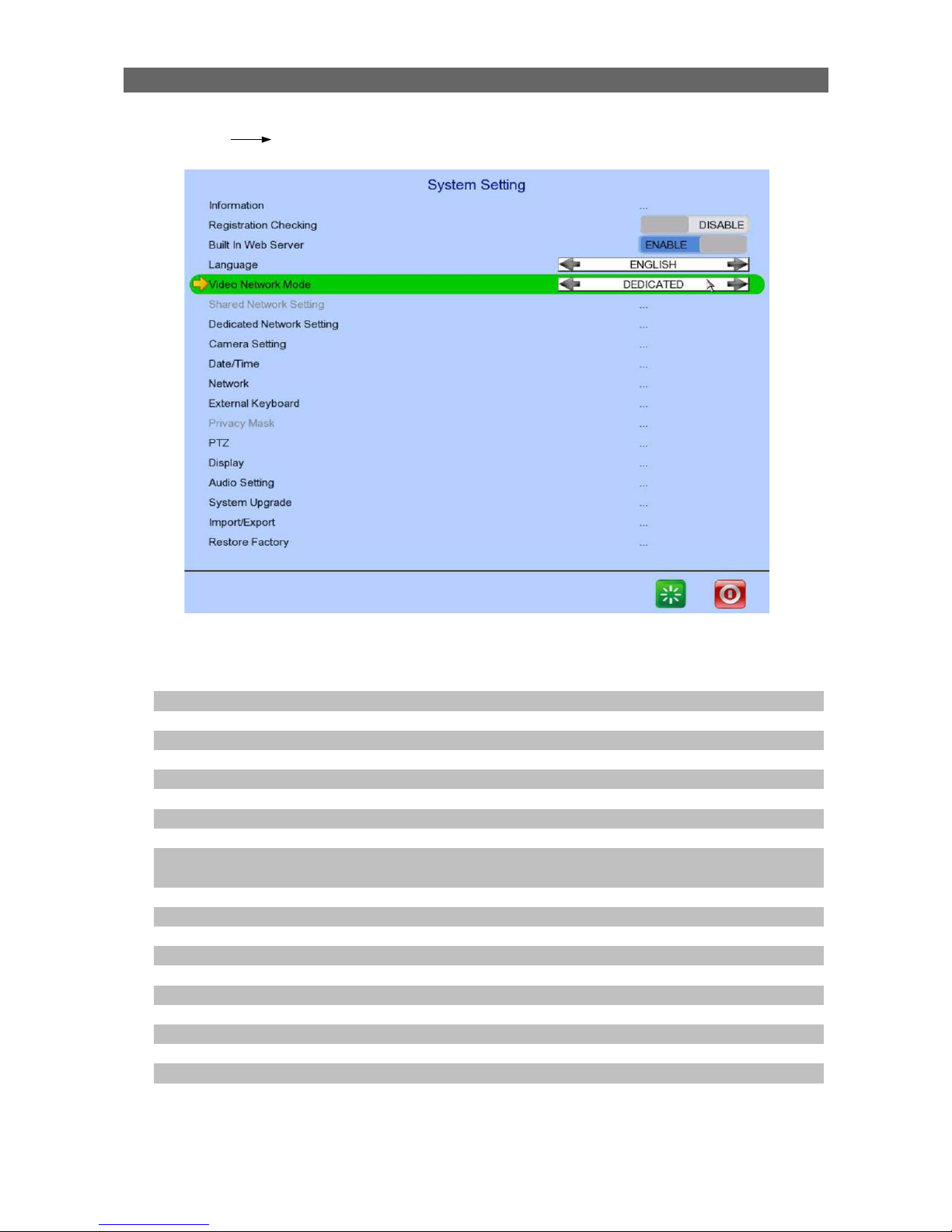
[Main Menu] [System]
Information Display general information of the digital video
recorder
Registration Checking Enable / disable remote registration check
Built In Web Server Enable / disable built in web server
Language Set display language
Video Network Mode Change video network mode
Shared Network Setting Change shared network mode settings
Dedicated Network Setting Change dedicated network settings
Camera Setting Change camera settings
Date /Time Change date and time settings
Network Change connection, throughput and 3G modem
settings
External Keyboard Set external keyboard settings
Privacy Mask Set PTZ privacy mask
PTZ Set PTZ arguments
Display Change local monitoring and audio settings
Audio Setting Set audio input and output
System Upgrade Upgrade system from USB device
Import /Export Import or export setting files
Restore Factory Restore default settings
Restart System Button Restart the system
Shutdown System Button Safe shutdown the system

User Guide PAGE 34
[Main Menu] [System] [Server Information]
Server Name Display name of the digital video recorder
Model Name Display model of the digital video recorder
Serial Number Display serial number of the digital video recorder
Firmware Version Display firmware version of the digital video recorder
CPLD Version Display CPLD version
IP Display IP address of the digital video recorder
Port Display port number of the digital video recorder
Subnet Mask Display subnet mask of the digital video recorder
Gateway Display gateway of the digital video recorder
Primary DNS Display primary DNS of the digital video recorder
Secondary DNS Display secondary DNS of the digital video recorder

User Guide PAGE 35
[Main Menu] [System] [Camera Setting]
Camera Select a camera
Installed Enable / disable the video channel
Name Change the name of camera
Swap Position Adjust the swap position
Brightness Set video brightness
Contrast Set video contrast
Saturation Set video saturation
Sharpness Set the sharpness to make video more sharp
Exposure Set the exposure when video is too dark
Mirror Set video mirroring to display image in different way
•
Normal :Normal display
•
H Flip :Left/right flip
•
V Flip :Top/down flip
•
HV Flip :Left/right flip + top/down flip
White Balance Set the white balance when video color displayed is not
correct
Flickerless Set the flickerless to match the environment

User Guide PAGE 36
Day Night Set the day night mode to match the environment
•
Auto :Auto adjustment
•
Day :Day mode only (color)
•
Night :Night mode only (black and white)
Sense Up Set video to sense up
Lens Zoom Set camera lens zoom
• OPTICAL ZOOM :support optical zoom only
• OPTI & DIGI ZOOM :support optical and
digital zoom
Vari-Focal [+/-] Adjust the focal
AI Sensitivity Set AI sensitivity
Iris Set video iris
DC Level Adjust the DC level
Focus [+/-] Adjust the focus
HD Resolution Adjust the resolution (702p/1080p)
Restore Default Restore camera factory settings
Undo Undo current change
[Main Menu] [System] [Date/Time]
Time Synchronization Enable Enable / disable time synchronization
Time Zone Set the time zone
Country Select a country
Date Set system date (Time sync disabled only)
Time Set system time (Time sync disabled only)
CHANGE TIME Save the time settings(Time sync disabled only)
Primary Time Server Set the primary time server(Time sync enabled only)
Secondary Time Server Set the secondary time server(Time sync enabled only)
Synchronize Time Perform time synchronization(Time sync enabled only)
User Guide PAGE 37
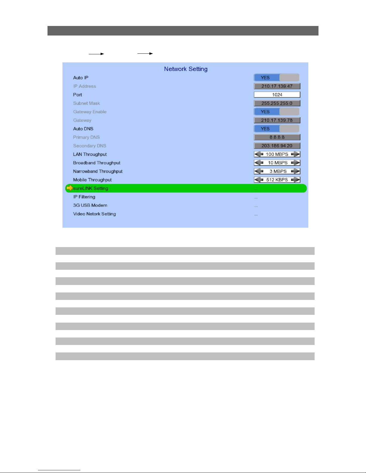
[Main Menu] [System] [Network Setting]
Auto IP Enable / disable auto IP from DHCP
IP Address Set IP address of the digital video recorder
Port Set port number of the digital video recorder
Subnet Mask Set subnet mask of the digital video recorder
Gateway Enable Enable / disable the gateway
Gateway Set gateway of the digital video recorder
Auto DNS Enable / disable auto DNS
Primary DNS Set primary DNS of the digital video recorder
Secondary DNS Set secondary DNS of the digital video recorder
Broadband Stream Throughput Set the data rate of broadband connection
Narrowband Stream Throughput Set the data rate of narrowband connection
Mobile Stream Throughput Set the data rate of mobile connection
sureLINK Setting Change sureLINK settings
IP Filtering Change IP filtering settings
3G USB Modem Change 3G modem settings
Video Network Setting Change video network settings

User Guide PAGE 38
[Main Menu] [System] [Network Setting] [sureLINK Setting]
Enable Enable / disable sureLINK function
sureLINK Address Set the sureLINK address of the digital video recorder
Refresh Period Set the sureLINK refresh rate
[Main Menu] [System] [Network Setting] [IP Filtering]
Mode Set the IP filtering mode
•
Disable :Disable IP filtering
•
Allow :Only allow selected IP address to connect
•
Deny :Disallow selected IP address to connect
Filtered IP Address Set the IP range to be filtered

User Guide PAGE 39
[Main Menu] [System] [Network Setting] [IP Filtering]
[Filtered IP Address]
No. Show the IP filtering entry number
Start IP Address Show starting IP of the filtered IP range
End IP Address Show ending IP of the filtered IP range
Add Add an IP filtering entry
Delete Delete the selected IP filtering entry
Delete All Delete all IP filtering entries
Show previous / next page of filtered IP address
[Main Menu] [System] [Network Setting] [IP Filtering]
[Filtered IP Address] [Add]
Start IP Address Set starting IP to be filtered
End IP Address Set ending IP to be filtered
Add Add the filter entry
User Guide PAGE 40
[Main Menu] [System] [Network Setting] [IP Filtering]
[Filtered IP Address] [Edit IP Filter]
Press enter or double click on an existing entry to enter [Edit IP Filter] menu.
Start IP Address Change starting IP of the filtering range
End IP Address Change ending IP of the filtered range
Edit Edit the filter entry
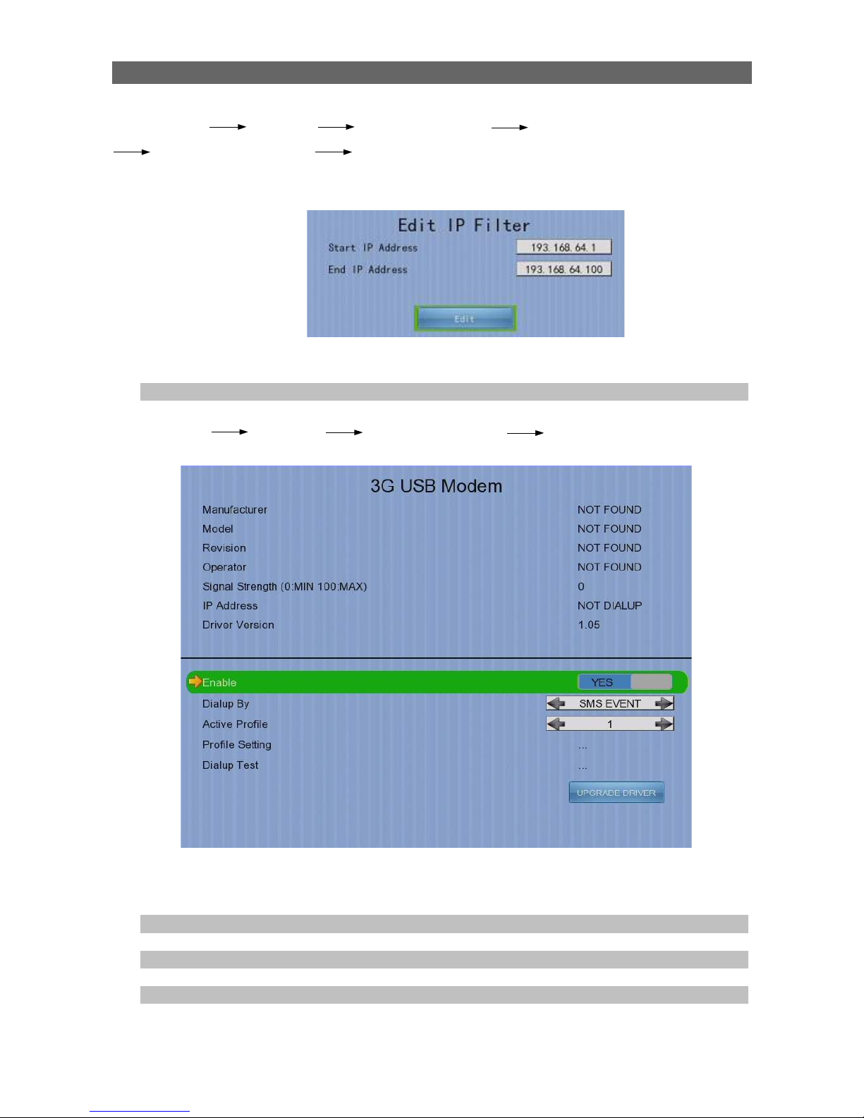
[Main Menu] [System] [Network Setting] [3G USB Modem]
Manufacturer Manufacturer name
Model Model
Revision Firmware version
Operator 3G network operator
Signal Strength 3G network signal strength from 0 to 100
IP Address 3G network IP
Driver Version Modem driver version
User Guide PAGE 41
Enable Enable/ disable 3G modem
Dialup By Set dialup mode
•
SMS EVENT :Dialup triggered by sms message
• STARTUP :Dialup after GX startup
Active Profile Set profile for 3G dialup
Profile Setting Change profiles settings
Dialup Test Start dialup test
UPGRADE DRIVER Upgrade 3G modem driver from USB device
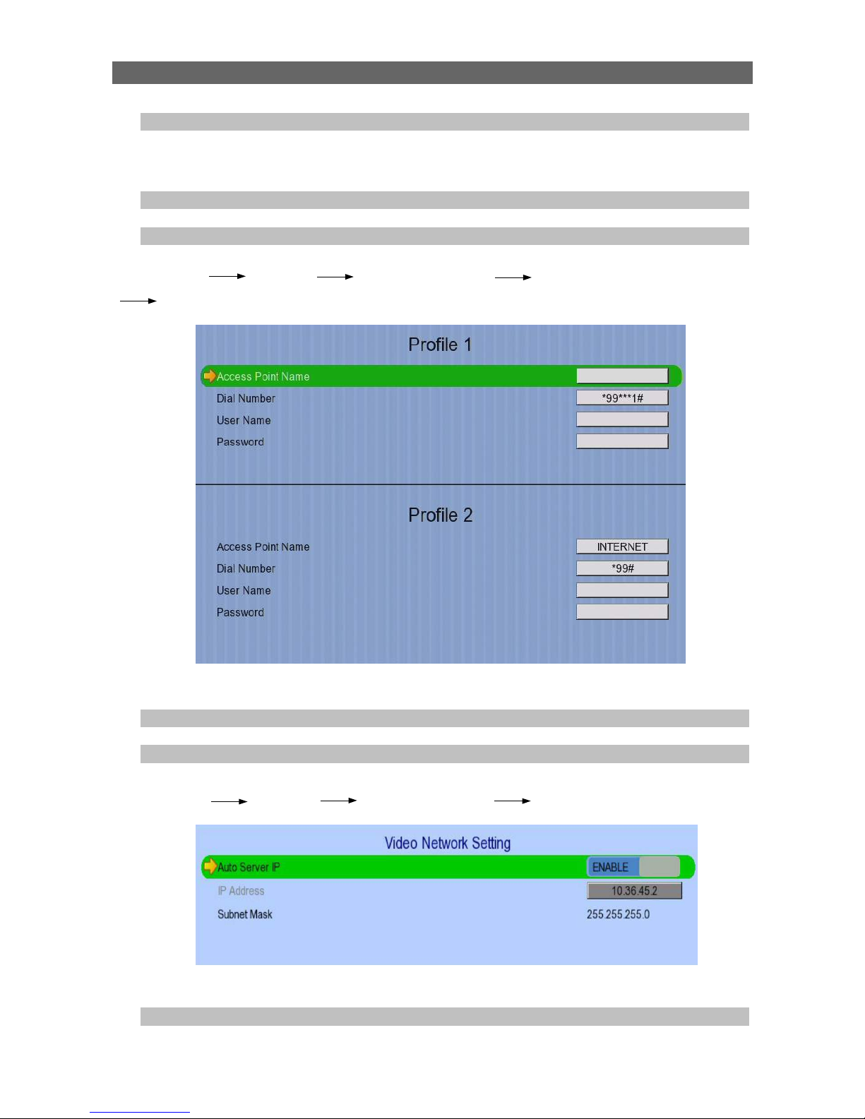
[Main Menu] [System] [Network Setting] [3G USB Modem]
[Profile Setting]
Access Point Name Dialup Access Point Name
Dial Number Dialup Number
User Name 3G network login user name
Password 3G network login password
[Main Menu] [System] [Network Setting] [Video Network Setting]
Auto Server IP Enable / Disable the video network setting
IP Address Set the IP address
Subnet Mask Display subnet mask of the digital video recorder
User Guide PAGE 42
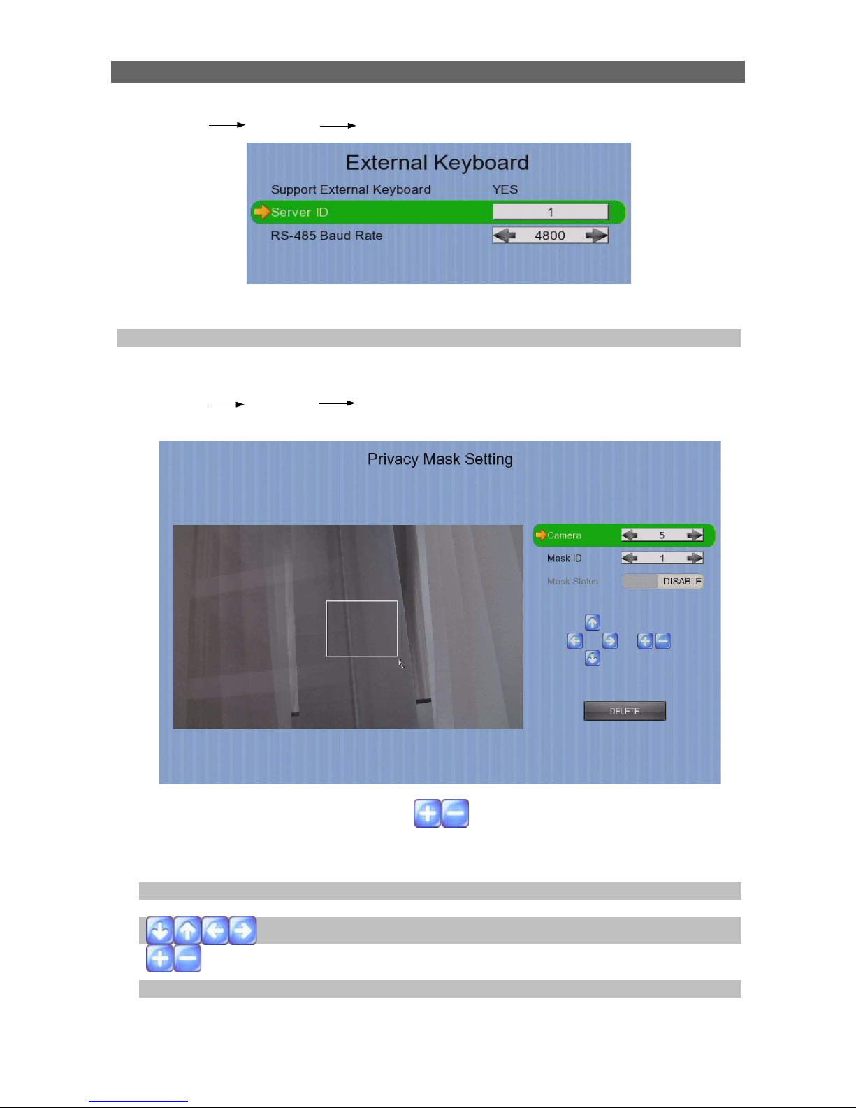
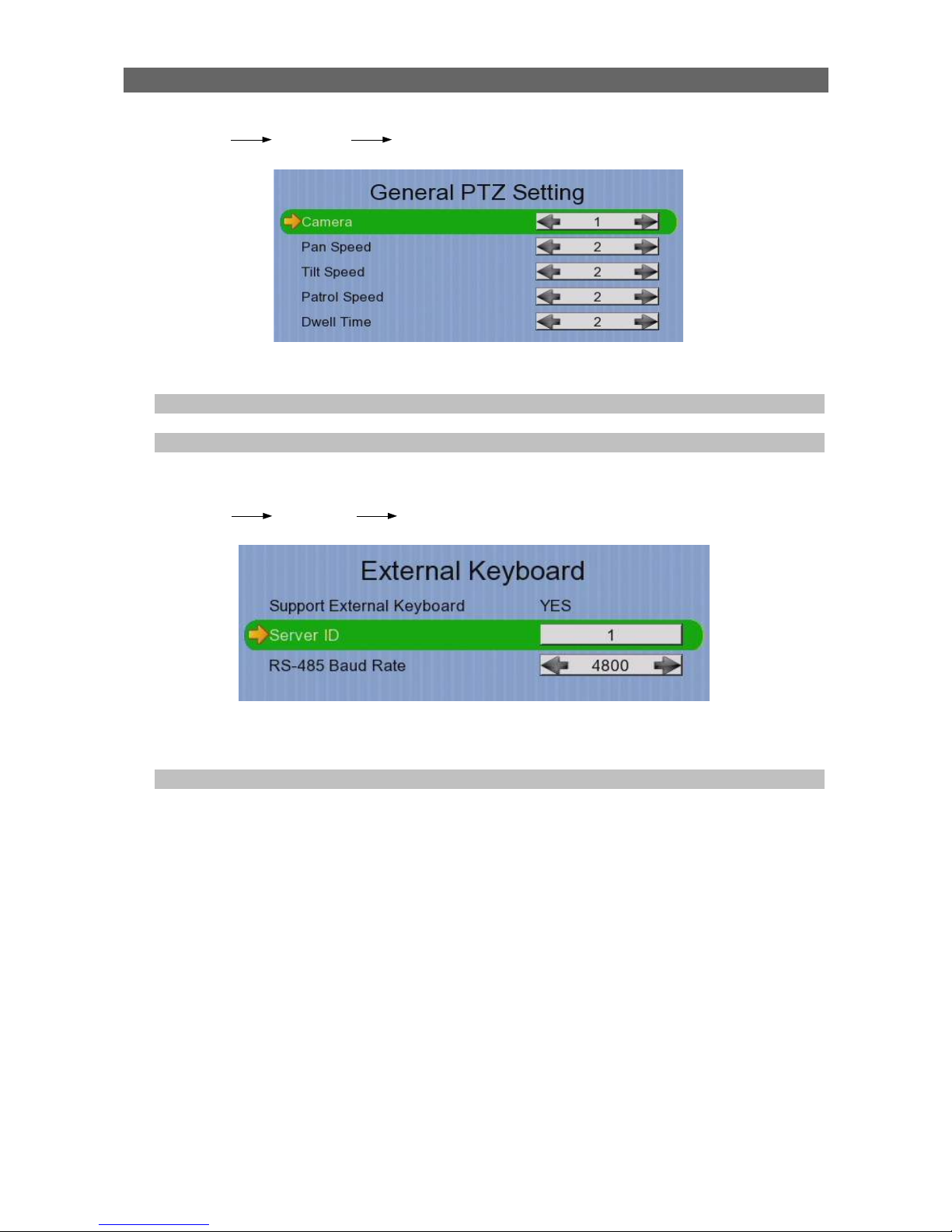
[Main Menu] [System] [External Keyboard]
Support External Keyboard Display support of external keyboard
Server ID Set DVR id for PTZ control
RS-485 Baud Rate Set RS-485 input baud rate
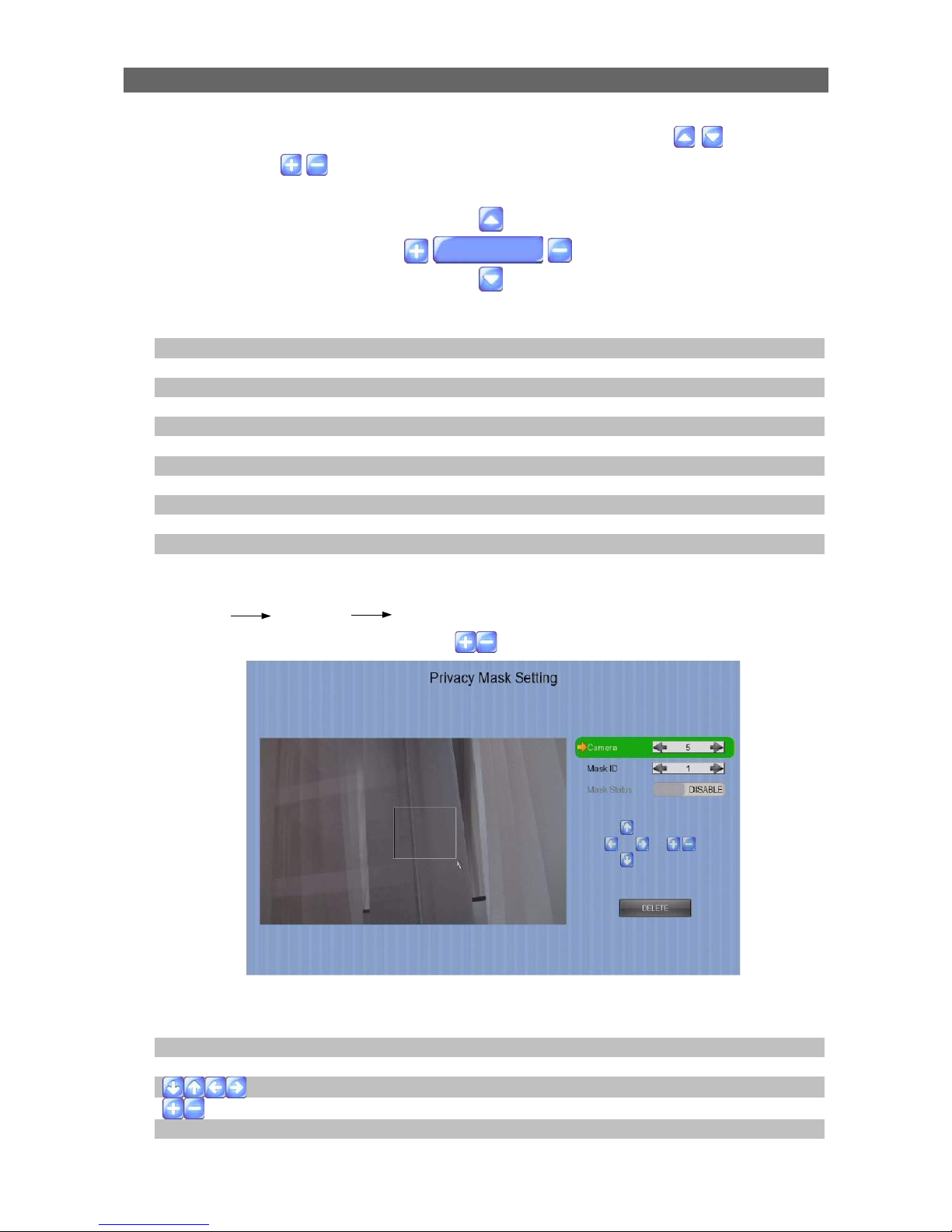
[Main Menu] [System] [Privacy Mask ]
User can draw privacy mask by mouse or buttons
Camera Selected video channel
Mask ID Selected privacy mask id
Mask Status Enable /disable current privacy mask
change current camera center
Edit size of selected privacy mask
DELETE Delete current privacy mask

User Guide PAGE 43
[Main Menu] [System] [General PTZ Setting]
Camera Selected video channel
Pan Speed Set pan speed
Tit Speed Set tilt speed
Patrol Speed Set patrol speed
Dwell Time Set dwell time for patrol
[Main Menu] [System] [Display Setting]
Server Name Set name of video server
Date Time Position Set the position for displaying system time
Camera Name Enable Display / hide camera name
Sequential Time Set the switch time between cameras in sequential mode
Sequential Camera Choose cameras displayed in full screen sequential
mode
Default Display Mode Set the default display mode
OSD Font Color Set the font color of OSD items
Video Out Resolution Set the output display resolution
Change Resolution Confirm the change in output resolution
Display Refresh Refresh the display in case something goes wrong

User Guide PAGE 44
[Main Menu] [System] [Audio Setting]
Hardware Support Display audio feature is supported by video server
Channel Set input audio channel
Channel Installed Enable /disable audio selected input channel
Channel Source Select source of audio
•
BUILT IN : use video server on board audio input
• CAMERA : use external camera audio input
PA Channel Set PA channel
PA Installed Enable /disable PA channel
PA Channel Source Select PA channel source
•
BUILT IN : use video server on board audio output
• CAMERA : use external camera audio output
Live Output Select audio live output channel
[Main Menu] [System] [Lock Keys]
Lock Keys Manually enable lock key
Auto Key Lock Set the auto lock key time

User Guide PAGE 45
[Main Menu] [System] [System Upgrade]
Progress Bar Display the upgrade progress
Upgrade Upgrade the firmware from USB flash device
[Main Menu] [System] [Import /Export]
Import Import settings from USB flash device
Export Export settings to USB flash device
User Guide PAGE 46
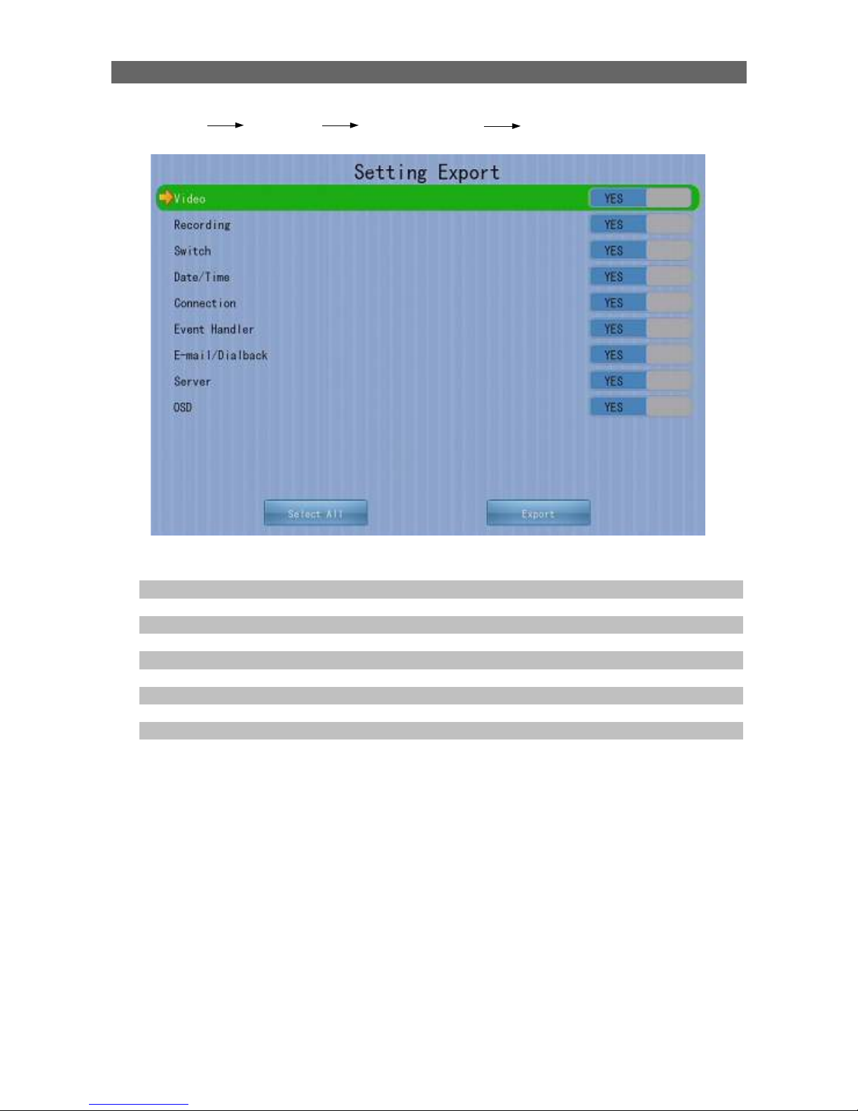
[Main Menu] [System] [Import /Export] [Export]
Video Export camera settings if selected
Recording Export recording settings if selected
Switch Export switch settings if selected
Date/Time Export date/time settings if selected
Connection Export network settings if selected
Event Handler Export event settings if selected
E-mail/Dialback Export e-mail and dialback settings if selected
Server Export server settings if selected
OSD Export OSD settings if selected
Select All Select / deselect all settings
Export Export the selected settings to USB flash device

User Guide PAGE 47
[Main Menu] [Event Status]
Alarm Trigger Show alarm trigger status
Alarm Tamper Show alarm tamper status
Motion Show motion status
Video Loss Show video loss status
Arm/Disarm Tamper Show arm/disarm tamper status
Security Switch Tamper Show security switch tamper status
System Tamper Show system tamper status
Power Failure Show power failure input status
Disk Full Show hard disk usage status
HDD Fault Show hard disk available status
System Restart Show system restart status
Clear Event Clear event that has already reset

User Guide PAGE 48
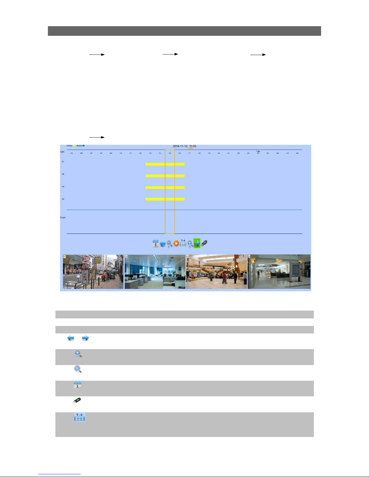
[Main Menu] [Playback]
Date Show date of recording log
Time Show time of recording log
1, 2, ... 16 Show cameras that performed recording in yellow bars
Event Select Display detail of the selected event
Show previous / next page of recording log
Display recording log in smaller time scale
Display recording log in bigger time scale
Search recording log by date and time
Extract video from selected time slot
Search a camera record

User Guide PAGE 49
[Main Menu] [Playback] [Search By Date]
Date Set the search date
Time Set the search time
Today Set date and time to current time
OK Search for log closest to the date and time
[Main Menu] [Switch]
Switch 1 – Switch 4 Toggle the status of the switch
Switch Setting Change switch settings
[Main Menu] [Switch] [Switch Setting]
ID Select the switch
Switch X Name Change the name of switch X
Switch X Type Change the type of switch X
•
Latching : Turn on for a period of time
•
Push button : Turn off 1 second after it is turned on
Switch X Normal State Change the normal state of switch X
•
N.O. : Normal open
• N.C. : Normal close
Action Delay Action setting - set the time between turning off and on
Latch Duration Action setting - set the time for turning on the switch

User Guide PAGE 50
[Main Menu] [Event Handler]
Arm/Disarm Change arm/disarm settings
Security Switch Change security switch settings
(Arm/Disarm enabled with Hardware Arm mode only)
Alarm Change individual alarm settings
Motion Change motion detection settings
Video Loss Change video loss event settings
System Tamper Change system tamper event settings
Power Failure Change power failure event settings
Disk Usage Change disk usage warning event settings
HDD Fault Change HDD fault event settings
System Restart Change system restart event settings
User Guide PAGE 51
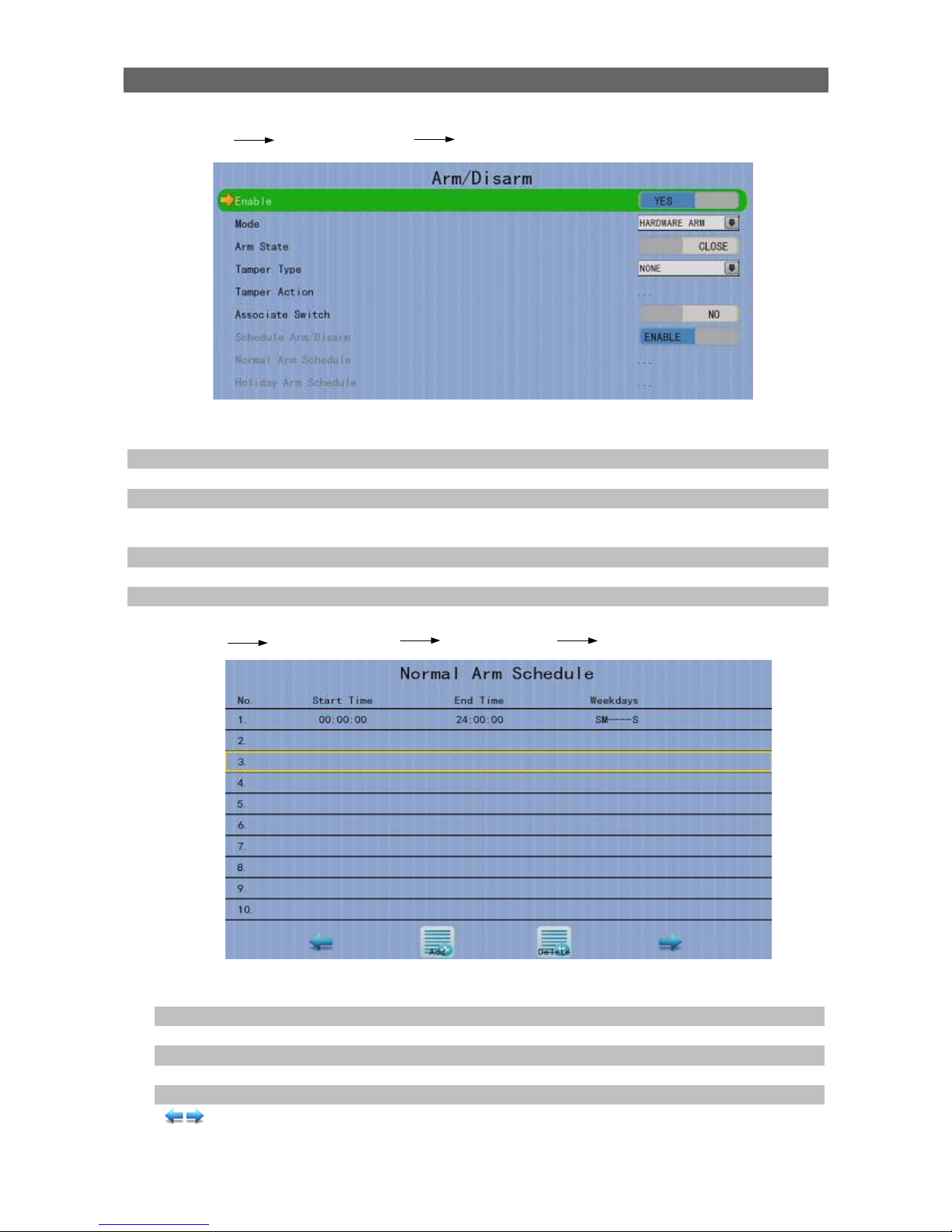
[Main Menu] [Event Handler] [Arm/Disarm]
Enable Enable / disable the arm/disarm control
Mode Select the arm/disarm mode
Arm State Select circuit open/close as system armed (Hardware Arm only)
Tamper Type Set the tamper detection type (Hardware Arm only)
Tamper Action Set actions taken when arm input tampered(Hardware Arm
only)
Associate Switch Associate switch 1 to arm/disarm control status
Schedule Arm/Disarm Enable / disable schedule arm/disarm (Schedule Arm only)
Normal Arm Schedule Set weekly arm/disarm schedule (Schedule Arm only)
Holiday Arm Schedule Set holiday arm/disarm schedule (Schedule Arm only)
[Main Menu] [Event Handler] [Arm/Disarm] [Normal Arm Schedule]
No. Show the schedule number
Start Time Show the start time of system armed
End Time Show the end time of system armed
Weekdays Show the weekdays the schedule applied to
Add Add a normal arm schedule
Delete Delete the selected normal arm schedule
Show previous / next page of schedules

User Guide PAGE 52
[Main Menu] [Event Handler] [Arm/Disarm] [Normal Arm Schedule]
[Add]
Weekdays Set the weekdays the new schedule applied to
Start Time Set the start time of new schedule
End Time Set the end time of new schedule
Add Add the new normal arm schedule
[Main Menu] [Event Handler] [Arm/Disarm] [Holiday Arm Schedule]
No. Show the schedule number
Start Date Show the start date of schedule
End Date Show the end date of schedule
Start Time Show the start time of system armed
End Time Show the end time of system armed
Add Add a holiday arm schedule
Delete Delete the selected holiday arm schedule
Show previous / next page of schedules
User Guide PAGE 53
[Main Menu] [Event Handler] [Arm/Disarm] [Holiday Arm Schedule]
[Add]
Start Date Set the start date of new schedule
End Date Set the end date of new schedule
Start Time Set the start time of new schedule
End Time Set the end time of new schedule
Add Add the new holiday arm schedule
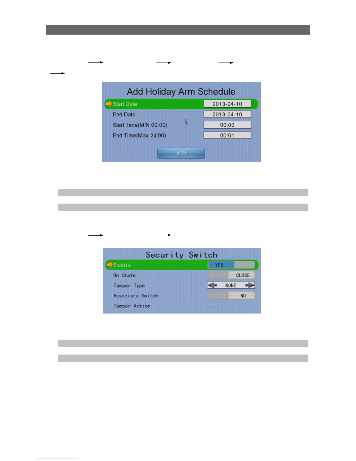
[Main Menu] [Event Handler] [Security Switch]
Enable Enable / disable the security switch
On State Select circuit open/close as security switch on
Tamper Type Set the tamper detection type
Associate Switch Associate switch 2 to security switch status
Tamper Action Set actions taken when security switch is tampered

User Guide PAGE 54
[Main Menu] [Event Handler] [Alarm]
Alarm Select an alarm
Enable Enable / disable selected alarm
Name Change the name of alarm
Source Type Select source of alarm
•
BUILT IN : use video server on board alarm
• CAMERA : use external camera alarm
Sensor Type Select circuit open/close as normal alarm state
Tamper Type Set the tamper detection type
Zone Type Set the zone type:
Entry Delay Set the entry delay time (Entry/Exit Zone only)
Exit Delay Set the exit delay time (Entry/Exit Zone only)
Action Set actions taken when alarm is triggered or tampered
ENABLE/DISABLE ALL Enable / disable all alarm
User Guide PAGE 55
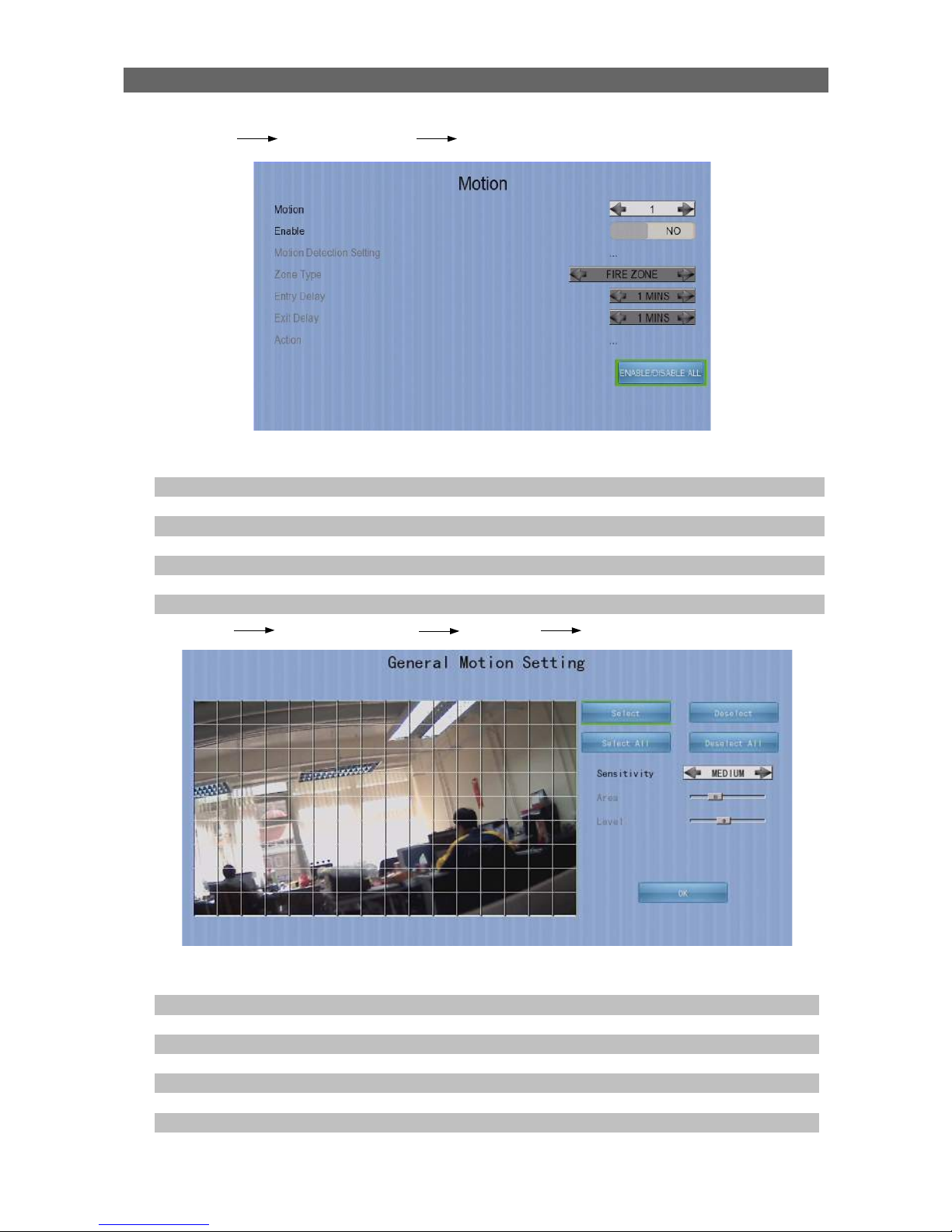
[Main Menu] [Event Handler] [Motion]
Camera Select a camera
Enable Enable / disable motion event
Motion Detection Setting Set motion detection settings
Zone Set the zone type:
Entry Delay Set the entry delay time (Entry/Exit Zone only)
Exit Delay Set the exit delay time (Entry/Exit Zone only)
Action Set actions taken when motion is detected
ENABLE/DISABLE ALL Enable / disable all motion
[Main Menu] [Event Handler] [Motion] [Motion Detection Setting]
Select Select motion blocks
Deselect Deselect motion blocks
Select All Select all motion blocks
Deselect All Deselect all motion blocks
Sensitivity Set the sensitivity level
Area Set the area sensitivity (Custom sensitivity only)
Level Set the light sensitivity (Custom sensitivity only)
OK Save the motion detection settings
User Guide PAGE 56
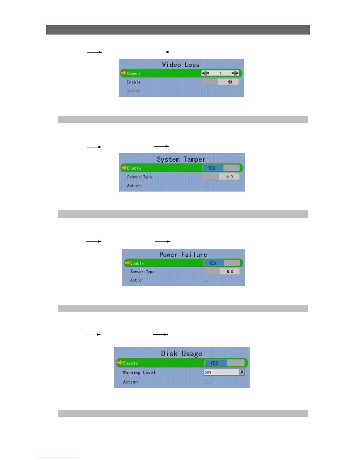
[Main Menu] [Event Handler] [Video Loss]
Camera Select a camera
Enable Enable / disable video loss event
Action Set actions taken when video loss is detected
[Main Menu] [Event Handler] [System Tamper]
Enable Enable / disable system tamper event
Sensor Type Select circuit open/close as normal state
Action Set actions taken when system tamper is triggered
[Main Menu] [Event Handler] [Power Failure]
Enable Enable / disable power failure event
Sensor Type Select circuit open/close as normal state
Action Set actions taken when power failure is detected
[Main Menu] [Event Handler] [Disk Usage]
Enable Enable / disable disk full event
Warning Level Set the warning level
Action Set actions taken when disk usage exceeds warning level

User Guide PAGE 57
[Main Menu] [Event Handler] [HDD Fault]
Enable Enable / disable the HDD Fault event
Action Set actions taken when disk failure or lost
[Main Menu] [Event Handler] [System Restart]
Enable Enable / disable the system restart available event
Action Set actions taken when system restart abnormally
[Main Menu] [Event Handler] Any Event [Action]
Recording Change event recording settings
Switch Change event switch settings
Dial Back Change dialback settings
E-mail Change e-mail settings
SMS Change SMS settings
Buzzer Change buzzer settings
Event LED Change event LED settings
Live Camera Change event associated live camera settings
PTZ Change event associated PTZ camera settings

User Guide PAGE 58
[Main Menu] [Event Handler] Any Event [Action] [Recording]
Enable Enable / disable event recording of that event
Recording Mode Set event recording frame rate
•
Auto :Record at highest achievable frame rate.
The storage size is large.
•
1 fps :Record at 1 frame per second. Storage
size is comparably small
Duration After Event
Clear
Set the post-event recording time
Recording Camera Select cameras performing event recording
[Main Menu] [Event Handler] Any Event [Action] [Switch]
Enable Enable / disable switch action of that event
Switch Select switches turning on when event triggers
General Switch Setting Set the latch duration and action delay
[Main Menu] [Event Handler] Any Event [Action] [Dial Back]
Enable Enable / disable dialback action of that event
Retry Duration (Sec) Set the time between each dialback retrial
Retry Count Set the number of retrial if dialback fails
Entry X Change the settings of dialback entry X
Dial Back Test Start the dial back test

User Guide PAGE 59
[Main Menu] [Event Handler] Any Event [Action] [Dial Back]
[Dial Back Entry]
Enable Enable / disable the dialback entry
IP Address Set the dialback IP address when event triggers
Port Set the dialback port when event triggers
[Main Menu] [Event Handler] Any Event [Action] [E-mail]
Enable Enable / disable e-mail action of that event
Image Attachment Associate
Camera
Change event associated camera for image
attachment
SMTP Server Change SMTP settings
E-mail X Set the e-mail address of recipient X
Sender E-mail Set the e-mail address of sender
Action Delay Set the minimum time between 2 e-mails of the same
event
Max Number of E-mail Set the maximum e-mails of an event until event clear
E-mail Test Start the e-mail test

User Guide PAGE 60
[Main Menu] [Event Handler] Any Event [Action] [E-mail]
[SMTP Server]
Server Address Set the SMTP server address
Port Set the SMTP server port
Authentication Is authentication required for the SMTP server
User Name Set user name used in authentication
Password Set password used in authentication
Network Setting Change the network settings
Time Out Set the allowed time of sending an e-mail in each trial
(in minute)
Retry Set the number of retrial if fails to send the mail
[Main Menu] [Event Handler] Any Event [Action] [SMS]
Enable Enable / disable SMS action of that event
Phone Number Set recipient phone number
Action Delay Set the minimum time between 2 SMS of the same event
Max SMS Set the maximum SMS of an event until event clear
SMS Test Start the SMS test

User Guide PAGE 61
[Main Menu] [Event Handler] Any Event [Action] [Buzzer]
Enable Enable / disable buzzer action of that event
Action Delay Set the time between turning off and next turning on
Duration Set the time for turning on the buzzer
[Main Menu] [Event Handler] Any Event [Action] [Event LED]
Enable Enable / disable LED action of that event
[Main Menu] [Event Handler] Any Event [Action] [Live Camera]
Enable Enable / disable live camera action of that event
Associate Camera Select cameras to be displayed when event triggers
[Main Menu] [Event Handler] Any Event [Action] [PTZ]
Enable Enable / disable live camera action of that event
Associate Camera Select PTZ cameras to be displayed when event triggers
Preset Number Select preset position of PTZ camera when event triggers

User Guide PAGE 62
[Main Menu] [Footage Extraction]
USB Storage Device Select device for saving the footage
FORMAT Format the selected USB device
Mode Set extraction mode
-Normal: Extract at the same recording frame rate, with audio
-Quick: Extract selected cameras at low frame rate, no audio
Channel Choose video channels to extract(Select or Quick mode only)
Start Date Set start date of the footage
Start Time Set start time of the footage
Duration Set video length of the footage
Protection Enable / disable password protection
Password Set extraction password(Password protection enabled only)
EXTRACT Start backup using above settings
[Main Menu] [User]
Security Mode Select security mode
Advanced :Log in and access right required
Current User Display current log in user
Add Account Add new account (Advanced mode only)
Edit/Delete Account Edit or remove an account (Advanced mode only)
Power On Default Right Access right when not logged in (Advanced mode only)
Log out User log out (Advanced mode only)
Log In As Other User User log in (Advanced mode only)
(* For execution, local password of current user is required in advanced mode)
User Guide PAGE 63
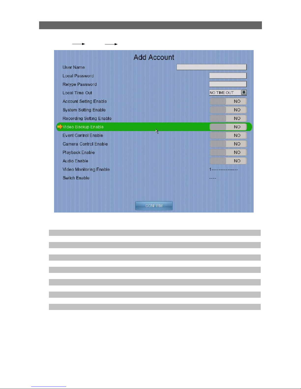
[Main Menu] [User] [Add Account]
User Name User name of new account(4 – 16 characters)
Local Password Password for local log in (4 – 10 characters)
Retype Local Password Confirming the password
Local Time Out Set the auto logout time when no local operation
Account Setting Enable Access right setting
System Setting Enable Access right setting
Recording Setting Enable Access right setting
Video Backup Enable Access right setting
Event Control Enable Access right setting
Camera Control Enable Access right setting
Playback Enable Access right setting
Audio Enable Access right setting
Video Monitoring Enable Access right setting
Switch Enable Access right setting
CONFIRM Create the account

User Guide PAGE 64
[Main Menu] [User] [Edit/Delete Account]
Most settings are the same as [Add Account] menu.
Local Login Enable Enable / disable local log in (with remote log in right only)
SAVE Save the account settings
DELETE Delete the account
Show settings of previous / next account
[Main Menu] [User] [Power On Default Right]
Most settings are the same as [Add Account] menu.
SAVE Save the access rights when server startup or local user log out

User Guide PAGE 65
4.3. Basic Operation
4.3.1. View Live Video
Depends on the model of the TeleEye GX HD Digital Video Recorder, user can view up to
16 live videos at the same time. User can also choose to supervise the video channel one
by one using the sequential mode function.
A. By Front Panel Buttons
Press button 1 to 9 to select Camera 1 to 9.
Press button 0 first, then press button 0 to 6 to select Camera 10 to
16.
Hold down button 0 for a few seconds to change the display
resolution.
Display next page of cameras (e.g. Cam 2, Cam 3).
Hold down the button for a few seconds to start sequential mode.
Switch to next screen mode (e.g. Full 2x2).
Hold down both buttons for a few seconds to refresh the local display.
When OSD menu is opened, the control buttons won’t take effect
B. By Mouse
(Right click)
Open the [Screen Selection] menu
(Left click)
Click on [1] to [16] to display that camera in full screen.
Click on [All], [Mode] and [next] to display in different modes or
other sets of cameras.
Click on [Sequential] to start sequential mode.

User Guide PAGE 66
4.3.2. Recording
To suit different situations, TeleEye GX supports 3 recording modes: manual recording,
schedule recording and event recording. When a camera is recording, the icon will be
shown next to its name and the LED will light up in red color.
• Manual Recording The start/stop operation is controlled manually by
operator. Recording will be performed on all cameras
once started. When manual recording is on, schedule
recording will be disabled.
• Schedule Recording Recording will be started and stopped according to user
defined schedules. Schedules are set on a weekly basis.
When schedule recording is enabled, manual recording
will be disabled.
• Event Recording Event recording will be activated if an event is triggered
with its recording action enabled. It can be performed
with manual recording or schedule recording
simultaneously. Detail description and setup procedure
will be given later in the Advanced Operation section.
To change recording mode quickly, either press on the front panel, or right click mouse
to open [Screen Selection] and click [Recording].
Recording Quick menu for selecting recording mode
• Off:Disable recording
• On:Enable recording of all cameras
• Schedule:Enable schedule recording

User Guide PAGE 67
To change other recording settings or edit recording schedules, go to the following menus:
[Main Menu] [HDD/Recording]
Disk Management View hard disk information
Format and scan disk
Recording Select the recording mode
Image Size Set recording resolution
•
720P :1280 x 720
•
Q720P :640 x 360
Video Quality Set video quality
Frame Rate Set recording frame rate, applied to all cameras
•
Auto :Record at highest achievable frame rate
•
1 fps :Record at 1 frames per second
•
Custom :Enable custom frame rate for individual
camera
Custom Frame Rate Set recording frame rate of individual cameras
Disk Mode Set disk mode
•
Cyclic :Remove oldest data when hard disk full
•
Fixed :Stop recording when hard disk full
Schedule Recording View or change recording schedules
Recording Retention Set recording retention settings
Recover Retention Recover damaged recorded video

User Guide PAGE 68
[Main Menu] [HDD/Recording] [Schedule Recording]
Add Add a new recording schedule
Edit Edit the selected schedule
Delete Delete selected schedule
Delete Day Delete all schedules on the same day as the selected schedule
[Main Menu] [HDD/Recording] [Schedule Recording] [Add]
Recording Type Type of recording schedule
• Normal :Record when within schedule
• Motion :Record when motion detected and within
schedule
• Custom :Record based on individual camera setting
Weekdays Select the weekdays to apply the schedule
Start Time Set the start time of the schedule
End Time Set the end time of the schedule
Camera Select the cameras to apply the schedule
Frame Rate Set recording frame rate of the schedule
(not applicable for Custom frame rate)
ADD Confirm add the schedule setting
Motion Setting Set motion detection settings
User Guide PAGE 69
[Main Menu] [HDD/Recording] [Schedule Recording] [EDIT]
Most settings are the same as [Add] menu.
EDIT Confirm EDIT the schedule setting
4.3.3. Playback
TeleEye GX supports user to view recorded video while not affecting the recording
process. A maximum of 4 video channels can be played at the same time.
[Main Menu] [Playback]
Date Show date of recording log
Time Show time of recording log
1, 2, ... 16 Show cameras that performed recording in yellow bars
Event Select Display detail of the selected event
Show previous / next page of recording log
Display recording log in smaller time scale
Display recording log in bigger time scale
Search recording log by date and time
Extract video from selected time slot
Search a camera record

User Guide PAGE 70
[Main Menu] [Playback] [Search By Date]
Date Set the search date
Time Set the search time
Today Set date and time to current time
OK Search for log closest to the date and time
4.3.4. PTZ
When observing video from local monitor, user can select individual video channel by
using panel keys , , , or (mouse left click). Selected video channel will be
pointed by icon. User can press or (mouse left click) to take PTZ control, then
the selected channel will be highlighted by icon (Only digital PTZ control can be taken,
or If the video channel not support analog PTZ control). For analog PTZ supported
channel, User can click or for taking PTZ command after the command box pop-
up on video monitoring screen. User can deselect the PTZ control channel by using or
, then the video channel will be pointed by icon.
OSD object selection Digital /Analog PTZ
control
PTZ tite up
PTZ tite down
PTZ pan left
PTZ pan right
PTZ function (only for
analog PTZ)
PTZ command subtract
(only for analog PTZ)
PTZ command add
(only for analog PTZ)
PTZ command box
(only for analog PTZ)
PTZ command down
(only for analog PTZ)
PTZ command up
(only for analog PTZ)
User Guide PAGE 71
For analog PTZ control, user can select different PTZ command by buttons, and
control the value by buttons.
ZOOM Control zoom in or out
RECALL PRESET:X Recall saved preset position
PROGRAM PRESET:X Edit preset position
AUTO PAN Start auto pan
FOCUS Control focus near or far
IRIS Control iris on or off
RECALL PATROL:X Recall saved patrol
STOP PATROL Stop patrol
CLEAR PATROL Clear patrol 1
START TOUR REC Start tour recording
STOP TORU REC Stop tour recording
SET LIFT LIMIT Set life limit position for auto pan
SET RIGHT LIMIT Set right limit position for auto pan
[Main Menu] [System] [Privacy Mask Setting]
User can draw privacy mask by mouse or buttons.
Camera Selected video channel
Mask ID Selected privacy mask id
Mask Status Enable /disable current privacy mask
change current camera center
Edit size of selected privacy mask
DELETE Delete current privacy mask
ZOOM
User Guide PAGE 72
[Main Menu] [System] [General PTZ Setting]
Camera Selected video channel
Pan Speed Set pan speed
Tit Speed Set tilt speed
Patrol Speed Set patrol speed
Dwell Time Set dwell time for patrol
[Main Menu] [System] [External Keyboard]
Support External Keyboard Display support of external keyboard
Server ID Set DVR id for PTZ control
RS-485 Baud Rate Set RS-485 input baud rate
User Guide PAGE 73
4.4. Advanced Operation
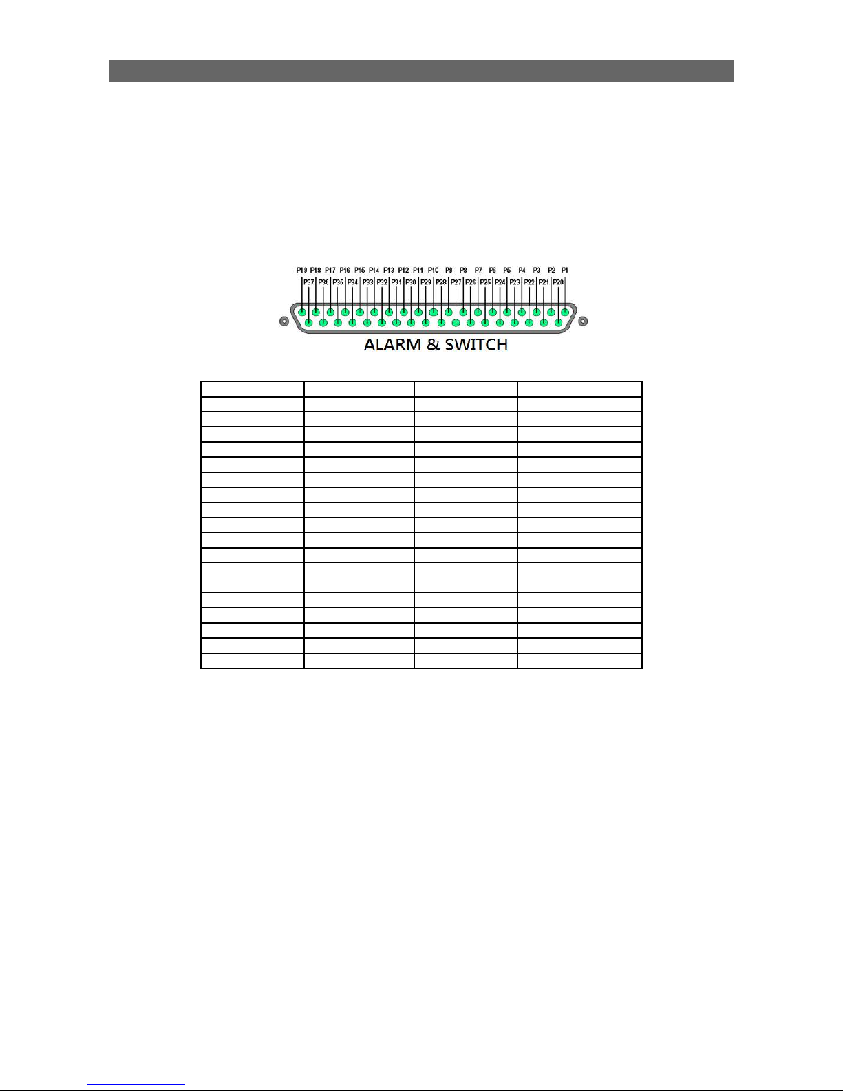
4.4.1. Install Alarm Sensors and Relay Control Port
TeleEye GX supports up to 16 alarm ports with tamper detection for connecting with alarm
sensors, 4 additional input sensors and 4 relay ports for control. The definitions of alarm
and relay control ports are shown in the following diagram.
Pin assignment for TeleEye GX
Pin 1 Alarm 1 Pin 20 GND
Pin 2 Alarm 2 Pin 21 GND
Pin 3 Alarm 3 Pin 22 GND
Pin 4 Alarm 4 Pin 23 GND
Pin 5 Alarm 5 Pin 24 GND
Pin 6 Alarm 6 Pin 25 GND
Pin 7 Alarm 7 Pin 26 GND
Pin 8 Alarm 8 Pin 27 GND
Pin 9 Alarm 9 Pin 28 Arm/Disarm
Pin 10 Alarm 10 Pin 29 Security Switch
Pin 11 Alarm 11 Pin 30 Power Failure
Pin 12 Alarm 12 Pin 31 System Tamper
Pin 13 Alarm 13 Pin 32 Alarm 14
Pin 14 Alarm 15 Pin 33 Alarm 16
Pin 15 Relay 0a Pin 34 Relay 0b
Pin 16 Relay 1a Pin 35 Relay 1b
Pin 17 Relay 2a Pin 36 Relay 2b
Pin 18 Relay 3a Pin 37 Relay 3b
Pin 19 N/A
4.4.2. Install Tamper Circuit and External Resistors
TeleEye GX supports tamper detection on all alarm inputs including arm/disarm input,
security switch input, system tamper and power failure input.
DEOL : Dual End of Line termination with NC and NO connection
SEOL : Single End of Line termination with NC and NO connection
NC/NO : Alarm and other input ports without tamper detection circuit connection
For example: By connecting the tamper circuit with DEOL, the circuit is in the normal close
condition if the resistance between point A and B detects 1.2kΩ (shown as below),
whereas the circuit is in normal open condition if the resistance between point A and B
detects 7.2kΩ. The resistance transition from 1.2kΩ to 7.2kΩ is generated by an alarm
tamper event for normal close circuit. The setup configuration of those alarms and input
ports are shown in the following diagrams. The circuit debouncing time between each
sensor is 20 milliseconds.
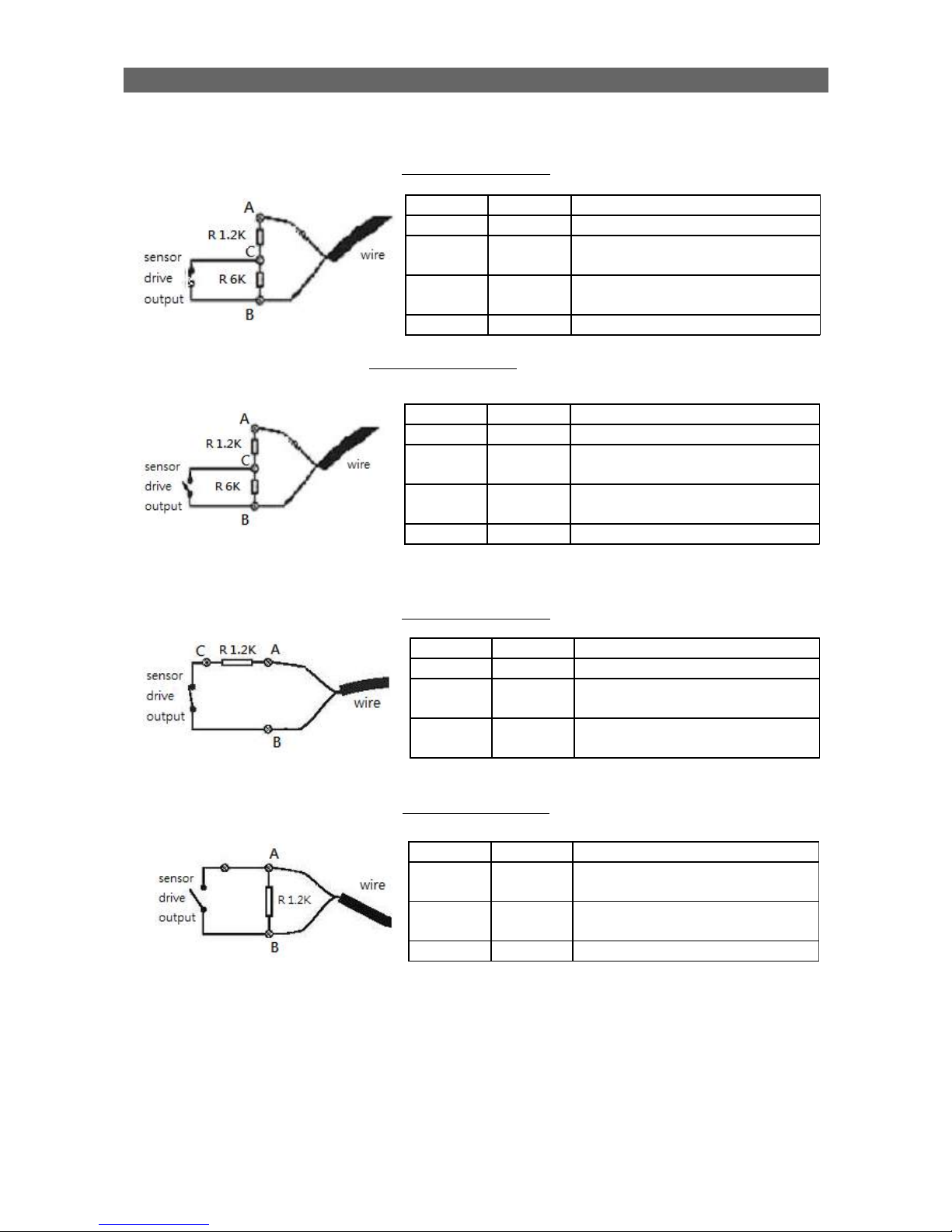
User Guide PAGE 74
Dual End of Line Configuration
Normal Close (NC)
Normal Open (NO)
Single End of Line Configuration
Normal Close (NC)
Normal Open (NO)
Term Status Description
S/C Tamper Wire short (point A and B)
LoZ Normal Sensor drive output close
(point B and C)
O/C Alarm Sensor drive output open
(point B and C)
Term Status Description
S/C Alarm Sensor drive output close
(point A and B)
LoZ Normal Sensor drive output open
(point A and B)
O/C Tamper Wire open (point A and B)
Term Status Description
S/C Tamper Wire short (point A and B)
LoZ Normal Sensor drive output close
(point B and C)
HiZ Alarm Sensor drive output open
(point B and C)
O/C Tamper Wire open (point A and B)
Term Status Description
S/C Tamper Wire short (point A and B)
LoZ Normal Sensor drive output close
(point B and C)
HiZ Alarm Sensor drive output open
(point B and C)
O/C Tamper Wire open (point A and B)
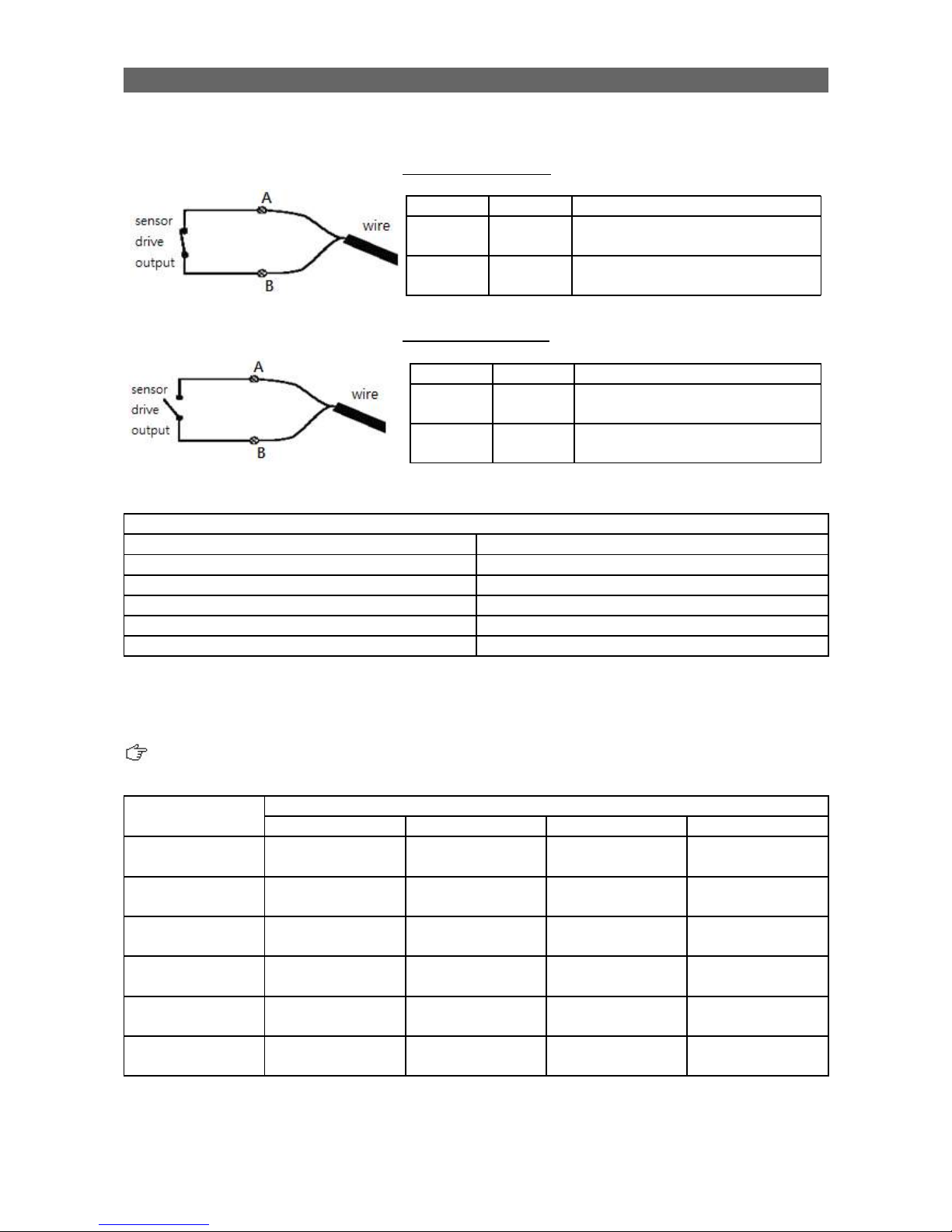
User Guide PAGE 75
Without Tamper Detection Circuit Configuration
Normal Close (NC)
Normal Open (NO)
Legend
NO Normally open alarm
NC Normally close alarm
O/C Open circuit
S/C Close circuit
LoZ Low impedance
HiZ High impedance
The table below shows the summary between the resistance network and the condition
result.
This table is provided as a reference. There may be a 10% tolerance for the resistance
value.
Condition Resistance (Ω)
0 - 400 401 - 2780 2781 – 29.5k 29.5k - infinity
DEOL (Normal
Close)
Tamper Short Normal (Close) Alarm (Open) Tamper Open
DEOL (Normal
Open)
Tamper Short Alarm (Close) Normal (Open) Tamper Open
SEOL (Normal
Close)
Tamper Short Normal (Close) Alarm (N/A) Alarm (Open)
SEOL (Normal
Open)
Alarm (Close) Normal (Open) Alarm (N/A) Tamper Open
NC without
tamper
Normal (Close) Alarm (N/A) Alarm (N/A) Alarm (Open)
NO without
tamper
Alarm (Close) Alarm (N/A) Alarm (N/A) Normal (Open)
Alarm (N/A): Alarm is not applicable
Term Status Description
S/C Normal Sensor drive output close
(point A and B)
O/C Alarm Sensor drive output open
(point A and B)
Term Status Description
S/C Alarm Sensor drive output close
(point A and B)
O/C Normal Sensor drive output open
(point A and B)

User Guide PAGE 76
4.4.3. Event Handling
TeleEye GX HD Digital Video Recorder supports 9 types of event detection and their icons
are as follows.
1. Arm/Disarm
2. Security Switch
3. Alarm
4. Motion
5. Video loss
6. System Tamper
7. Power Failure
8. Disk Usage
9. HDD Fault
10.System Restart
Event Icons in Local Monitor
If an event is triggering, its respective icon will be flashing next to the camera name (for
motion, video loss) or at the bottom of the screen (for all other event types). If an event has
reset and the event status is not yet cleared, the icon will remain static on its original
position.
4.4.3.1 Arm/Disarm
Arm/Disarm input is used for enhancing security level of the surveillance area. This input
introduces the concept of 3 zone types of alarm and motion: fire zone, normal and
entry/exit zone.
Armed
If the system is armed, alarm sensor and motion that is set as normal zone can be
triggered immediately if someone triggers the sensor or motion detected. It is usually used
when there is no operator at surveillance area.
Disarmed
If the system is disarmed, alarm and motion events detected from sensors will not result in
an alarm and motion except the fire zone type alarm, motion and arm/disarm tamper. If
there are operators at surveillance area, it is usually disarmed.
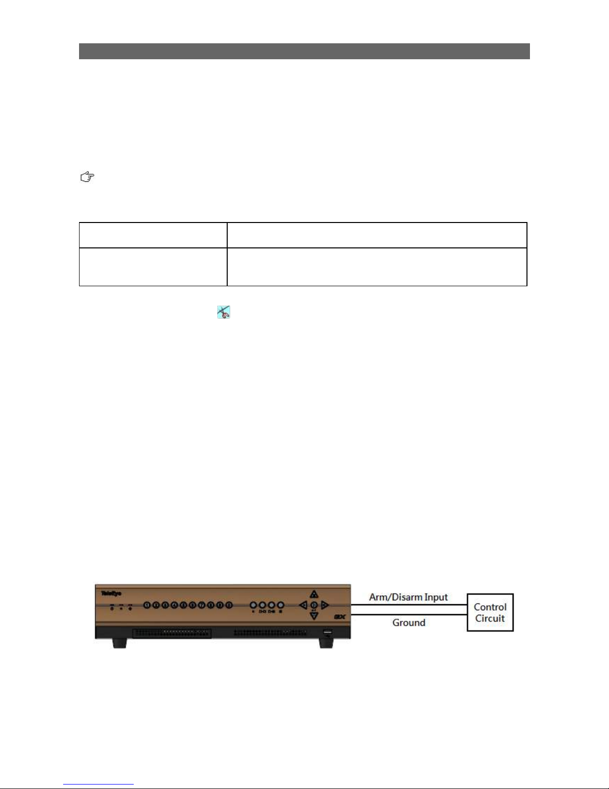
User Guide PAGE 77
Arm/Disarm Mode
TeleEye GX supports 3 different modes of arm/disarm operation:
•
Hardware: Use Arm input to arm/disarm, suitable for local operation
•
Software: Use software to arm/disarm, suitable for remote operation
•
Schedule: Follow preset schedule to arm/disarm, suitable for unmanned location
Under software and schedule mode, the security switch is not applicable.
There are 2 types of arm schedules:
Normal Schedule User can set the arm period in terms of weekday. The
system would arm according to this weekly schedule.
Holiday Schedule User can set the arm date and period for specially
handled holiday. If the date is set to holiday schedule, it
will follow holiday schedule instead of normal schedule.
Arm/Disarm Tamper Type
Arm/Disarm tamper event triggers if someone cuts the wire between the arm/disarm input
and the digital video recorder. This event can be triggered once the wire is being cut.
Arm/Disarm tamper type has choice of none, SEOL and DEOL.
Arm State
If arm state is set to close, it indicates arm of TeleEye GX when the state of the circuit is
close and disarm of TeleEye GX when the circuit is open. Oppositely, if arm state is set to
open, it indicates arm and disarm of TeleEye GX when the state of the circuit is open and
close respectively.
Physical Configuration for Arm/Disarm
The arm/disarm input and ground of TeleEye GX HD Digital Video Recorder needs to
connect to a control unit which is commonly a switch or password panel for arm/disarm
input.

User Guide PAGE 78
[Main Menu] [Event Handler] [Arm/Disarm]
Enable Enable / disable the arm/disarm control
Mode Select the arm/disarm mode
Arm State Select circuit open/close as system armed(Hardware Arm
only)
Tamper Type Set the tamper detection type (Hardware Arm only)
Tamper Action Set actions taken when arm input tampered (Hardware Arm
only)
Associate Switch Associate switch 1 to arm/disarm control status
Schedule Arm/Disarm Enable / disable schedule arm/disarm (Schedule Arm only)
Normal Arm Schedule Set weekly arm/disarm schedule (Schedule Arm only)
Holiday Arm Schedule Set holiday arm/disarm schedule (Schedule Arm only)
[Main Menu] [Event Handler] [Arm/Disarm] [Normal Arm Schedule]
No. Show the schedule number
Start Time Show the start time of system armed
End Time Show the end time of system armed
Weekdays Show the weekdays the schedule applied to
Add Add a normal arm schedule
Delete Delete the selected normal arm schedule
Show previous / next page of schedules

User Guide PAGE 79
[Main Menu] [Event Handler] [Arm/Disarm] [Normal Arm Schedule]
[Add]
Weekdays Set the weekdays the new schedule applied to
Start Time Set the start time of new schedule
End Time Set the end time of new schedule
Add Add the new normal arm schedule
[Main Menu] [Event Handler] [Arm/Disarm] [Holiday Arm Schedule]
No. Show the schedule number
Start Date Show the start date of schedule
End Date Show the end date of schedule
Start Time Show the start time of system armed
End Time Show the end time of system armed
Add Add a holiday arm schedule
Delete Delete the selected holiday arm schedule
Show previous / next page of schedules
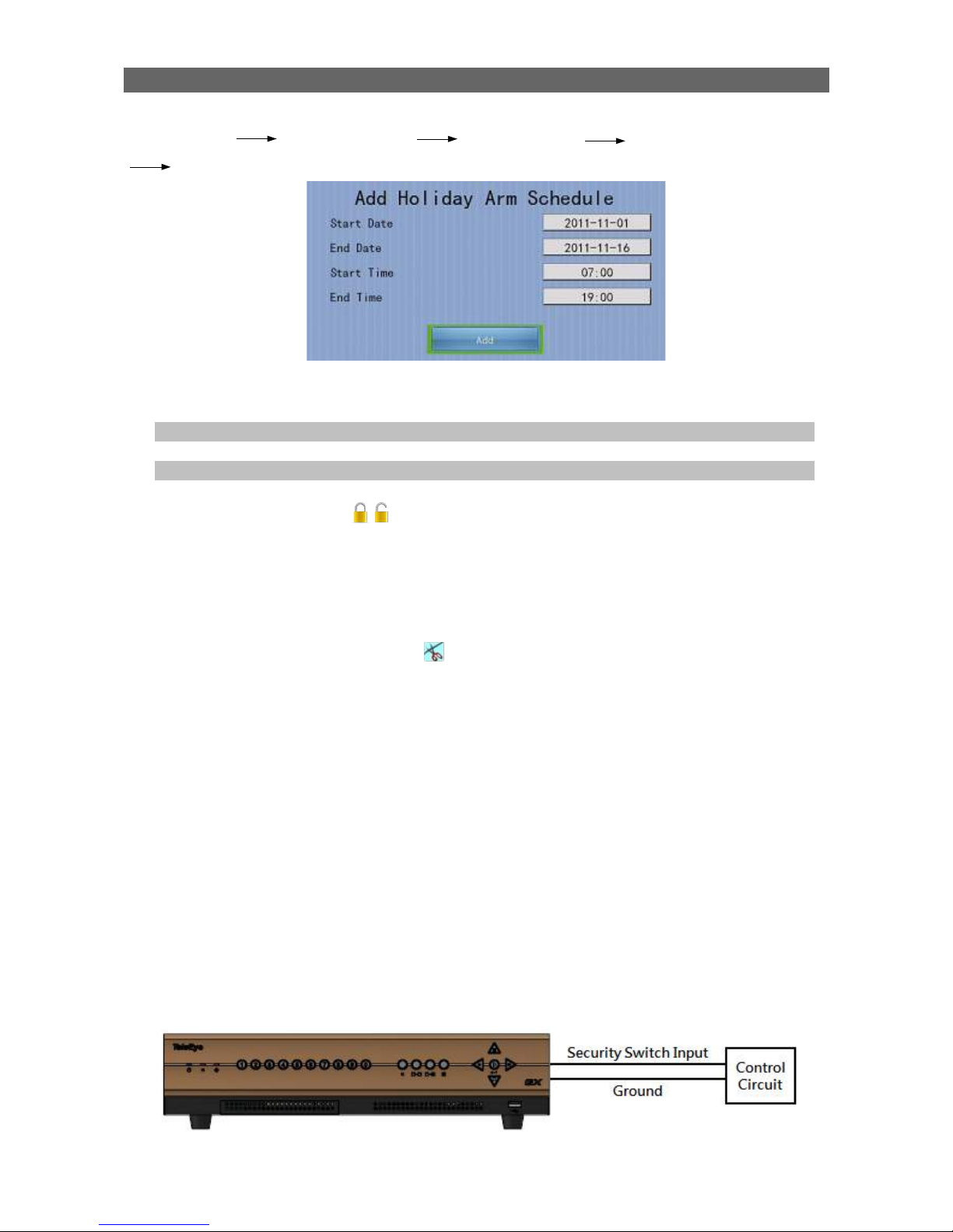
User Guide PAGE 80
[Main Menu] [Event Handler] [Arm/Disarm] [Holiday Arm Schedule]
[Add]
Start Date Set the start date of new schedule
End Date Set the end date of new schedule
Start Time Set the start time of new schedule
End Time Set the end time of new schedule
Add Add the new holiday arm schedule
4.4.3.2 Security Switch
It is an input to the digital video recorder for wiring a security switch. The purpose of the
security switch is to terminate the exit delay for exit zone alarm. If the security switch is on
and the system is armed, all exit delay will be terminated. If the security switch is off and
an entry alarm is triggered, entry delay will start.
•
Security Switch Tamper Type
Security switch tamper event triggers if someone cuts the wire between the security switch
input and the digital video recorder. This event can be triggered once the wire is being cut.
Security switch tamper type has choice of none, SEOL and DEOL.
•
On State
If security switch on state is set to close, it indicates security switch on and off of TeleEye
GX when the state of the circuit is closed and open respectively. Oppositely, if security
switch on state is set to open, it indicates security switch on and off of TeleEye GX when
the state of the circuit is open and closed respectively.
•
Physical Configuration for Security Switch
The security switch input and ground of TeleEye GX digital video recorder needs to
connect to a control circuit which is commonly the lock of the surveillance area for security
switch input.

User Guide PAGE 81
[Main Menu] [Event Handler] [Security Switch]
4.4.3.3 Alarm
It is an input to the digital video recorder from external alarm sensors. Alarm can be used
to detect many events occur at the surveillance area, such as fire and illegal entering by
someone. The alarm event supports BS 8418:2003 which has arm/disarm and security
switch functions.
•
Sensor Tamper Type
Alarm tamper event will be triggered if someone cuts the wire between the alarm input and
the digital video recorder. This event behaves as fire zone type that can be triggered once
the wire is being cut. Alarm tamper type has choice of none, SEOL and DEOL.
•
Sensor Type
If the alarm sensor input circuit type is normal close (NC), when the state of the circuit is
opened, it indicates alarm trigger of TeleEye GX, while nothing happens when the state of
the circuit is closed. If the alarm sensor input circuit type is normal open (NO), when the
state of the circuit is closed, it indicates alarm trigger of TeleEye GX, while nothing
happens when the state of the circuit is open.
•
Zone Type
All alarm sensors can be associated with zone types if Arm/Disarm input is installed.
Normal Zone This zone allows alarms to be triggered after system
armed.
Fire Zone This zone allows alarms to be triggered no matter which
arm state of the system is, i.e. armed or disarmed. It is
suitable for installation of fire detectors
Entry/Exit Zone This zone allows user to set the delay time for entering
or leaving the surveillance area without triggering any
alarm event. If alarm recording action is enabled,
recording starts at entry or exit time throughout the
delay.
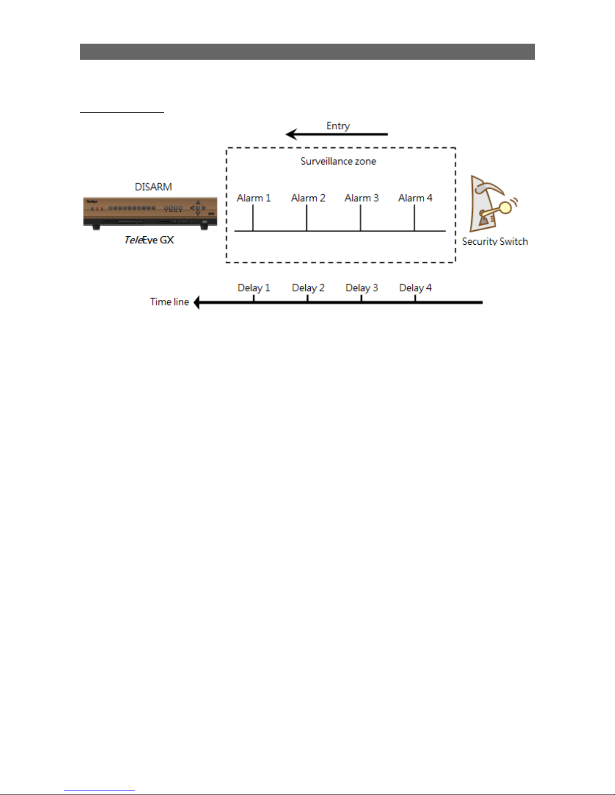
User Guide PAGE 82
Example of Entry/Exit Zone WITH Security Switch Usage
For Entry Zone:
The entry delay is the period of time between entering the surveillance zone and reaching
the digital video recorder. In order to disarm the system for maintenance or repair, user /
installer needs to turn off the security switch and enter the surveillance zone. The delay
timer starts from the 1st trigger by the 1st alarm sensor (i.e. Alarm 4). Note that if user
enables recording action, recording action is automatically activated during entry delay.
The detail description is shown as follows:
1. User turns off security switch
2. The alarm is set at entry delay
3. The 1st trigger is made by Alarm 4 (i.e. user enters the surveillance zone and the entry
delay time begins)
4. 2nd, 3rd and 4th trigger are made and each entry delay starts respectively
5. User disarms the system for maintenance
For example: If the time for going from security switch to digital video recorder is about 8
minutes, Delay 4 should be around 8 minutes, while Delay 3 should be longer than the
time for going from security switch to Alarm 3, and so on.

User Guide PAGE 83
For Exit Zone:
The exit delay is the period of time for leaving a surveillance zone without making false
alarm (i.e. Alarm 1 to Alarm 4). The purpose is to let the user / installer have enough time
to leave the surveillance zone after the digital video recorder is armed. User / installer can
set the delay time for each alarm. Note that if user enables recording action, recording will
be activated when an alarm is triggered during exit delay.
The detail description is shown as follows:
1. User arms the system
2. The alarm is set at exit delay and timer of all alarms begin
3. The 1st trigger is made by Alarm 1 (i.e. user leaves the surveillance zone)
4. 2nd, 3rd and 4th triggers are made respectively
5. User turns on the security switch or waits for all alarm exit delays to expire.
For example, if the time for leaving the surveillance zone is about 8 minutes, user should
adjust the delay time so that Delay 1 = leaving time between the digital video recorder and
Alarm 1, Delay 2 = leaving time between digital video recorder and Alarm 2, Delay 3 =
leaving time between digital video recorder server and Alarm 3 and Delay 4 should be 8
minutes. The alarm will be activated after the exit delay expired.

User Guide PAGE 84
Example of Entry/Exit Zone WITHOUT Security Switch Usage
For Entry Zone:
The entry delay is the period of time between entering the surveillance zone and
reachingthe digital video recorder. In order to disarm the system for maintenance or repair,
user / installer enters the surveillance zone. The delay timer starts from the 1st trigger by
the 1st alarm sensor (i.e. Alarm 4). Note that if user enables recording action, recording
action is automatically activated during entry delay.
The detail description is shown as follows:
1. The alarm is set at entry delay
2. The 1st trigger is made by Alarm 4 (i.e. user enters the surveillance zone and the entry
delay time begins)
3. 2nd, 3rd and 4th trigger are made and each entry delay starts respectively
4. User disarms the system for maintenance
For example: If the time for going from security switch to digital video recorder is about 8
minutes, Delay 4 should be around 8 minutes, while Delay 3 should be longer than the
time for going from security switch to Alarm 3, and so on.

User Guide PAGE 85
For Exit Zone:
The exit delay is the period of time for leaving a surveillance zone without making false
alarm (i.e. Alarm 1 to Alarm 4). The purpose is to let the user / installer have enough time
to leave the surveillance zone after the digital video recorder is armed. User / installer can
set the delay time for each alarm. Note that if user enables recording action, recording will
be activated when an alarm is triggered during exit delay.
The detail description is shown as follows:
1. User arms the system
2. The alarm is set at exit delay and timer of all alarms begin
3. The 1st trigger is made by Alarm 1 (i.e. user leaves the surveillance zone)
4. 2nd, 3rd and 4th triggers are made respectively
5. User waits for all alarm exit delays to expire.
For example, if the time for leaving the surveillance zone is about 8 minutes, user should
adjust the delay time so that Delay 1 = leaving time between d igital video recorder and
Alarm 1, Delay 2 = leaving time between digital video recorder and Alarm 2, Delay 3 =
leaving time between digital video recorder and Alarm 3 and Delay 4 should be 8 minutes.
The alarm will be activated after the exit delay expired.

User Guide PAGE 86
Different Combination of Cases of Arm/Disarm, Security Switch and Alarm for the 3
Zone Type
Initial State Step 1 Step 2 Step 3 Result
Alarm Arm Security
Switch
Fire Zone
No trigger Arm On Trigger alarm \ \ Alarm trigger
Arm Off Trigger alarm \ \ Alarm trigger
Arm Uninstall Trigger alarm \ \ Alarm trigger
Disarm \ Trigger alarm \ \ Alarm trigger
Uninstall \ Trigger alarm \ \ Alarm trigger
Uninstall Uninstall Trigger alarm \ \ Alarm trigger
Normal Zone
No trigger Arm On Trigger alarm \ \ Alarm trigger
Arm Off Trigger alarm \ \ Alarm trigger
Arm Uninstall Trigger alarm \ \ Alarm trigger
Disarm \ Trigger alarm \ \ No alarm trigger
Uninstall \ Trigger alarm \ \ Alarm trigger
Uninstall Uninstall Trigger alarm \ \ Alarm trigger
Entry/Exit Zone
No trigger Arm On Trigger alarm \ \ Alarm trigger
Disarm Off Arm.
Exit delay starts
Trigger alarm.
Recording starts
if action enabled
Security switch
on.
Exit delay ends.
Recording stops
Alarm can be
triggered any
time after that
Exit delay ends
after preset exit
time.
Recording stops
Alarm can be
triggered any
time after that
Arm On Security switch
off
Trigger alarm.
Entry delay
starts.
Recording starts
if action enabled
Disarm No alarm trigger.
Recording stops
Entry delay ends
after preset
entry time
Alarm trigger.
Recording don’t
stop unless
disarm
Disarm Uninstall\ Arm.
Exit delay starts
Trigger alarm.
Recording starts
if action enabled
Exit delay ends
after preset exit
time.
Recording stops
System enter
entry delay
automatically
after next alarm
trigger
Arm Uninstall Trigger alarm.
Entry delay
starts.
Recording starts
if action enabled
Disarm \ No alarm trigger.
Recording stops
Entry delay ends
after preset
entry time
\ Alarm trigger.
Recording don’t
stop unless
disarm
Disarm Trigger alarm \ \ No alarm trigger
Uninstall Trigger alarm \ \ Alarm trigger
Uninstall Uninstall Trigger alarm \ \ Alarm trigger
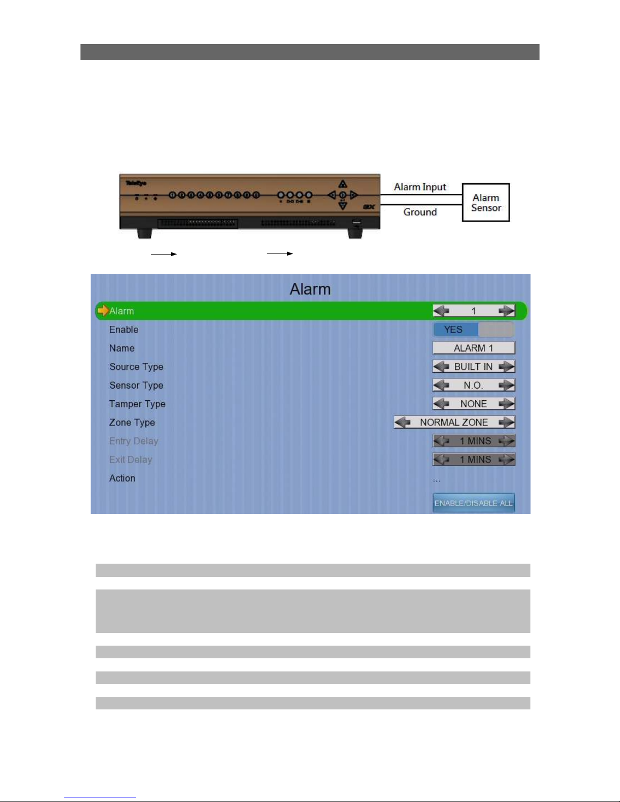
User Guide PAGE 87
Physical Configuration for Alarm
The alarm input and ground of TeleEye GX HD d igital video recorder need to connect to
various kinds of sensors which are commonly installed at entrance or special part of the
surveillance area.
[Main Menu] [Event Handler] [Alarm]
Alarm Select an alarm
Enable Enable / disable the alarm
Name Change the name of alarm
Source Type Select source of alarm
•
BUILT IN: use video server on board alarm
• CAMERA: use external camera alarm
Sensor Type Select circuit open/close as normal alarm state
Tamper Type Set the tamper detection type
Zone Set the zone type:
Entry Delay Set the entry delay time (Entry/Exit Zone only)
Exit Delay Set the exit delay time (Entry/Exit Zone only)
Action Set actions taken when alarm is triggered or tampered
ENABLE/DISABLE ALL Enable / disable all alarm
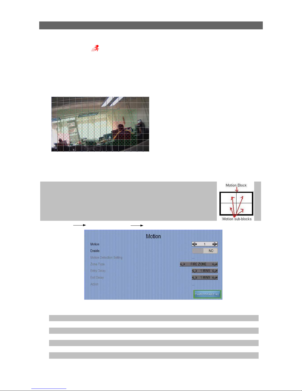
User Guide PAGE 88
4.4.3.4. Motion
Motion detection can be triggered when motion occurs on the camera. Motion detection
has different sensitivity levels, which can be set up individually on each video input
channel. There are generally 4 options: high, middle, low and custom. Custom option
allows user to select the sensitivity level and detection area themselves.
Sensitivity
Level The definition of level in motion detection is the difference in luminance level
between current and reference field. The level range is 1 to 10, with 1 being
the most sensitive and 10 being the least sensitive.
Area In motion detection, one selected motion block is
internally divided into four sub-blocks. The definition of
area is how many sub-blocks have detected motion in
order to trigger a motion event. Any value between 1 and
4 can be set. The more sub-blocks are selected, the
lower the motion sensitivity is.
[Main Menu] [Event Handler] [Motion]
Camera Select a camera
Enable Enable / disable motion event
Motion Detection Setting Set motion detection settings
Zone Set the zone type:
Entry Delay Set the entry delay time (Entry/Exit Zone only)
Exit Delay Set the exit delay time (Entry/Exit Zone only)
Action Set actions taken when motion is detected
ENABLE/DISABLE ALL Enable / disable all motion
Motion detection example:
The selected motion detection area
is the crossed area in green color.
The motion block will turn to red
color when movement is detected.
The normal display area cannot
detect any motion.

User Guide PAGE 89
[Main Menu] [Event Handler] [Motion] [Motion Detection Setting]
Select Select motion blocks
Deselect Deselect motion blocks
Select All Select all motion blocks
Deselect All Deselect all motion blocks
Sensitivity Set the sensitivity level
Area Set the area sensitivity (Custom sensitivity only)
Level Set the light sensitivity (Custom sensitivity only)
OK Save the motion detection settings
4.4.3.5 Video Loss
Video loss event will be triggered when the video channel input disappears, or the d igital
video recorder receives no signal from the camera. When this happens, a blue screen
would be displayed on the local monitor.
[Main Menu] [Event Handler] [Video Loss]
Camera Select a camera
Enable Enable / disable video loss event
Action Set actions taken when video loss is detected
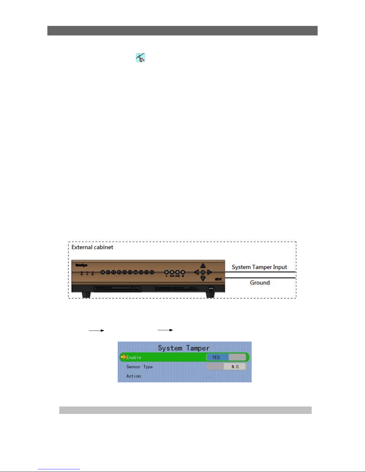
User Guide PAGE 90
4.4.3.6 System Tamper
It is an input to the digital video recorder for wiring a tamper switch of the external cabinet
outside the digital video recorder and its accessories. The purpose of system tamper event
is to prevent someone from breaking into the cabinet and destroying the digital video
recorder.
Sensor Type
If the system tamper input circuit type is normal close (NC), when the state of the circuit is
opened, it indicates system tamper of TeleEye GX, while nothing happens when the state
of the circuit is closed. If the alarm sensor input circuit type is normal open (NO), when the
state of the circuit is closed, it indicates system tamper of TeleEye GX, while nothing
happens when the state of the circuit is open.
Physical Configuration for System Tamper
The system tamper input and ground of TeleEye GX HD digital video recorder need to
connect to an external cabinet which is used for protecting the digital video recorder and
its accessories
[Main Menu] [Event Handler] [System Tamper]
Enable Enable / disable system tamper event
Sensor Type Select circuit open/close as normal state
Action Set actions taken when system tamper is triggered
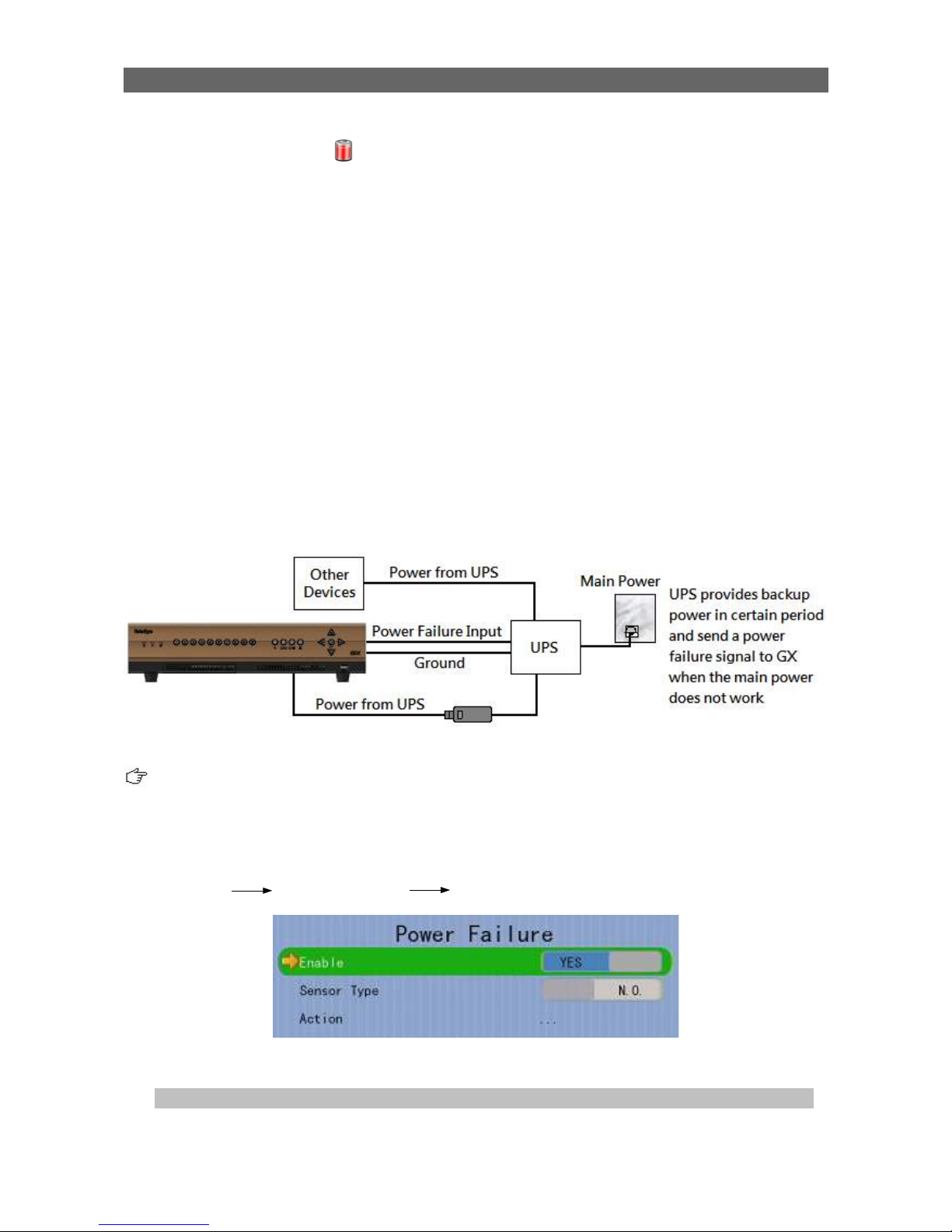
User Guide PAGE 91
4.4.3.7 Power Failure
It is an input to the digital video recorder typically used for wiring the output signal pin from
an uninterruptible power supply (UPS).
Sensor Type
If the power failure input circuit type is normal close (NC), when the state of the circuit is
opened, it indicates power failure of TeleEye GX, while nothing happens when the state of
the circuit is closed. If the alarm sensor input circuit type is normal open (NO), when the
state of the circuit is closed, it indicates power failure of TeleEye GX, while nothing
happens when the state of the circuit is open.
Physical Configuration for Power Failure Input
The power failure input and ground of TeleEye GX digital video recorder need to connect
to an universal power supply circuit UPS in order to detect any power failure condition.
The UPS circuit setup above is used as an example. Not all UPS have signal output.
Some UPS have self-testing for a period of time. Their signal output may toggle during
test.
[Main Menu] [Event Handler] [Power Failure]
Enable Enable / disable power failure event
Sensor Type Select circuit open/close as normal state
Action Set actions taken when power failure is detected
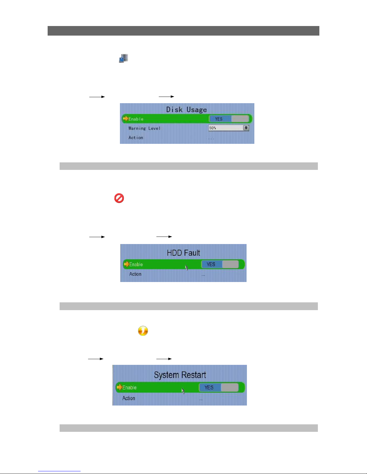
User Guide PAGE 92
4.4.3.8 Disk Usage
Disk full event will be triggered if hard disk usage exceeds user specified warning level. A
total of 6 warning levels can be selected: 50%, 60%, 70%, 80%, 90% and 100%.
[Main Menu] [Event Handler] [Disk Usage]
Enable Enable / disable disk full event
Warning Level Set the warning level
Action Set actions taken when disk usage exceeds warning level
4.4.3.9 HDD Fault
HDD fault event will be triggered when hard disk failure, bad health or hard disk change
with respect to checklist is detected.
[Main Menu] [Event Handler] [HDD Fault]
Enable Enable / disable the HDD fault event
Action Set actions taken when disk failure or lost
4.4.3.10 System Restart
System restart event will be triggered when abnormal restart of video recorder is detected.
[Main Menu] [Event Handler] [System Restart]
Enable Enable / disable the system restart event
Action Set actions taken when systemrestarted abnormallyy

User Guide PAGE 93
4.4.4. Event Action
TeleEye GX HD Digital Video Recorder supports 9 types of actions that can be activated
by any events mentioned in above section.
1. Recording
2. Switch
3. Dialback
4. E-mail
5. SMS
6. Buzzer
7. Event LED
8. Live Camera
9. PTZ
4.4.4.1. Recording
When an event is triggered, video recording will be performed on user selected cameras
with selected recording mode.
Pre-Event Recording
Pre-event recording allows video recording before an event is triggered. The period of pre-
event recording is between 1 and 2 minutes before the event is detected. User can find
that there is at least 1 more minute of video in the recording log before event triggering.
Post-Event Recording
After the event is reset, recording will continue until user defined duration time is reached.
[Main Menu] [Event Handler] Any Event [Action] [Recording]
Enable Enable / disable event recording of that event
Recording Mode Set event recording frame rate
•
Auto :Record at highest achievable frame rate.
The storage size is large.
•
1 fps :Record at 1 frame per second. Storage size
is comparably small.
Duration After Event Clear Set the post-event recording time
Recording Camera Select cameras performing event recording
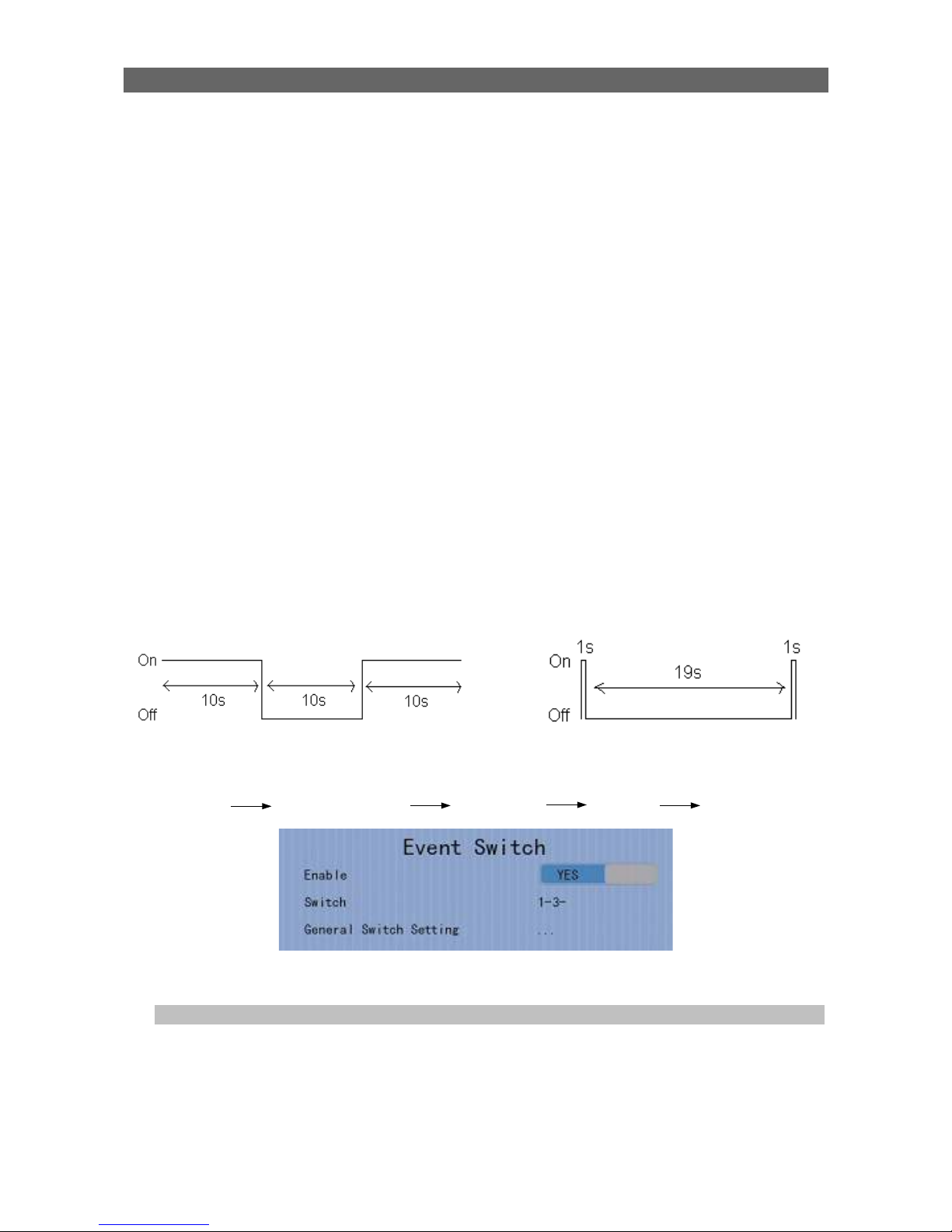
User Guide PAGE 94
4.4.4.2. Switch
The switch action allows the digital video recorder to control 4 external relays which are
defined by user.
Switch Type
Two types of switch are supported:
•
Latching : The switch turns on for a period of time.
•
Push-button: The switch turns off 1 second after it is turned on.
Latch Duration
Latch duration is the period of time for turning on the latching type switch.
Action Delay
Action delay is the period of time after the switch is turned off and before turning on again.
Example of Latch Duration and Action Delay
Assuming that the latch duration is 10sec and action delay is 10sec. If an event is
triggered, the on/off status of the switch versus time is shown below.
[Main Menu] [Event Handler] Any Event [Action] [Switch]
Enable Enable / disable switch action of that event
Switch Select switches turning on when event triggers
General Switch Setting Set the latch duration and action delay
Latching type switch
Push-button type switch

User Guide PAGE 95
4.4.4.3. Dialback
Dialback allows the digital video recorder to connect to one remote PC through TCP/IP
and displays live video in case an event is triggered. As a result, remote operator can
recognize what situation is at the surveillance area.
The Java web page can’t respond to this request, software like TeleEye sureSIGHT or
sureGUARD needs to be installed to the PC to perform dialback.
[Main Menu] [Event Handler] Any Event [Action] [Dial Back]
Enable Enable / disable dialback action of that event
Retry Duration (Sec) Set the time between each dialback retrial
Retry Count Set the number of retrial if dialback fails
Entry X Change the settings of dialback entry X
Dial Back Test Start the dial back test
[Main Menu] [Event Handler] Any Event [Action] [Dial Back]
[Dial Back Entry]
Enable Enable / disable the dialback entry
IP Address Set the dialback IP address when event triggers
Port Set the dialback port when event triggers
 Loading...