

Page 1
User Manual
Tele
Eye
DM587/DM589
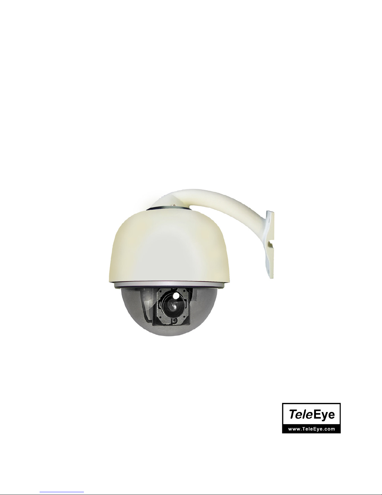
High Speed Dome
Before attempting to install or operate on this produce,
Please read this manual carefully and keep it for future use.
Page 2

1
Content
Chapter One Product Overview
I. Performance instruction…………………………………………………………………………………….…2
II. Notice………………………………………………………………...……………………………………….3
III Installation steps of shield dome……………………………………………………………………………..4
IV. Installation Instruction of the Acrylic Demo Shield…………………………………………………………6
V. Install Bend-Tube-Style Bracket……………………………………………………………………………..7
Chapter Two Wiring and Setup of Dome System
I. Wiring of Dome System………………………………………………………………………………………8
1. Minimum system connection……………………………………………………………………………8
2. Multi-dome device connection…………………………………………………………………….……8
II. Setting of Dome Device communication …………………………………………………..…………….…9
1. Setting protocol and baud rate of dome device…………………………………………………………9
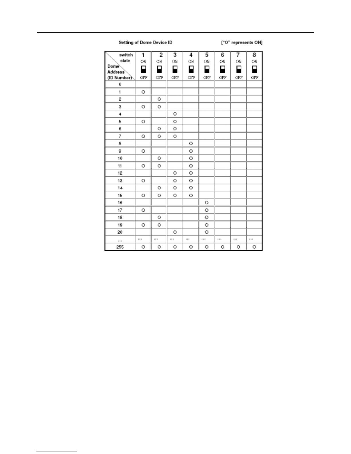
2. Address setting of dome device…………………………………………………………………………10
3. Setting of dome device ID………………………………………………………………………………11
Chapter Three Fast Operation Guide of Dome Device
I. Wiring…………………………………………………………………………………………………………12
II. Setting protocol and baud rate……………………………………………………………………….………12
III. Setting dome device address…………………………………………………………………………...……13
IV. Install camera……………………………………………………………………………………….….……13
V. Connect the power of dome device………………………………………………………………….….……13
VI. Controller setting……………………………………………………………………………………………13
VII. Start testing…………………………………………………………………………………………………13
VIII. Complete the test (Summary)………………………………………………………………...……………13
Chapter Four English Operation Menu of Dome Device
I. Main menu……………………………………………………………………………………………………14
II. Tree Menu List………………………………………………………………………………………………14
1. Language Options………………………………………………………………………………………14
2. Display options…………………………………………………………………………………………15
3. Control options…………………………………………………………………………………………16
4. Diagnostic Options…………………………………………………………………………..…………17
5. Camera Options…………………………………………………………………………………...……18
6. Function Programming…………………………………………………………………………………19
Chapter Five Short-cut Operations and Specification of Dome Device
1. Coding description of protocol and serial transmission rate:….………………………………………22
Chapter Six Trouble Shooting of Dome Device
1. Trouble shooting table…………………………………………………………………………………24
Page 3

2
Chapter One Product Overview
I. Performance instruction:
1. Address of Dome device is from 0~~~~255. The number (address) of dome device in the control system is setup by
the hardware (8-digit on and off switch) of dome device.
2. Integrate multi-protocol and auto protocol differentiation. Note: The dome device only auto
differentiate controller of the first communication.
3. Pan 360 degree continuous rotation....
4. Tilt 90 degree action plus 2 degree angle adjustment....
Plus the 2 degree adjustment, the view angle can be 90 or 92 degree.
5....Pan manual operation speed can be 0.1 to 280 degree per second
6....Tilt manual operation speed can be 0.1 to 120 degree per second
7. 128 pershot positions.(A fixed position that aimed by the dome camera, which can be set and revised by user
arbitrarily)
8. The maximum running speed when preshot is being called can reach 360 degree per second with
accuracy of ±0.1 degree.
9....Easy installation interface.
10....Pass environmental protection grade IP66 (outdoor type)
11....Adopts long distance RS-485 transmission mode
12....Transmission speed, i.e. Baud rate is selectable.(Set by the fifth and sixth bit of the on and off switch of the
dome device. 2400bps~19200bps)
Page 4

3
II. Notice:
Signal Communications Limited reserves the right to make improvements to the product
described in this manual at any time and without prior notice.
This manual is copyrighted. All rights are reserved. This manual may not be copied, reproduced
or translated in whole or part without prior consent from Signal Communications Limited.
Tele Eye is a trademark of Signal Communications Limited and is registered in China, Hong
Kong, US and other countries.
TeleEye's products are sold under the brand name of CAMERIO in Australia, Japan, Korea, New
Zealand, Taiwan and Argentina.
CAMERIO is a trademark of Signal Communications Limited and is registered in Australia, Japan,
Korea, New Zealand, Taiwan and Argentina.
All other trademarks are the property of their respective owners
Copyright (c) 2007 Signal Communications Limited (A Member of TeleEye Group). All rights
reserved.
Version 1.1
Limits of Liability and Disclaimer of Warranty
Signal Communications Limited has taken care in preparation of this manual, but makes no
expressed or implied warranty of any kind and assumes no responsibility for errors or omissions.
No liability is assumed for incidental or consequential damages in connection with or arising out
of the use of the information or accessories contained herein.
Features and specifications are subject to change without prior notice.
Page 5
4
1. Before installing the full-view High-Speed Dome Video Camera, please read this user’s manual first.
2. This unit should be operated only from the type of power source indicated on the marking
label found at the power adapter. If you are not sure of the type of power supply you plan to use,
consult your appliance dealer or local power company. For units intended to operate from
battery power or other sources, refer to operating instructions.
3. Inside the Dome device are precise optical and electrical instruments. Heavy pressure, shock and
other incorrect operations should be prevented during the processes of delivery, storage and installation.
Otherwise, it may cause damage on the product.
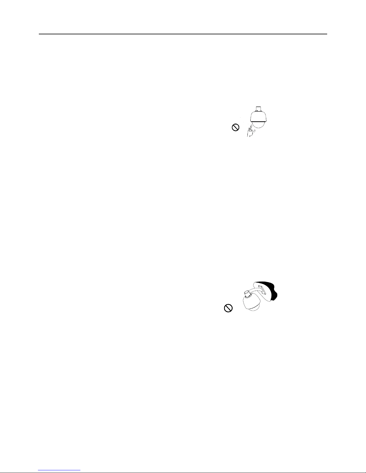
4. Please do not remove and disassemble any internal
components from the Dome video camera by yourself in order to avoid
normal usage being impacted. There is no parts inside
the device which can be repaired by the user himself.
5. Always conform to national and local safety codes during installation. Adopt the special power
provided with the Dome video camera. During transmission, RS-485 and video signal should be retained
enough distance with high-voltage equipments or cables. When necessary, thunder-proof, surge-proof
and other protecting measures should be carried out.
6. Please avoid exposing the Dome video camera to rain or the humidity, etc. Please do not use the
product in humid place. If the video camera is installed in outdoor area, please ensure the device being
protected by a weather-proof, sealed shield. Exposure to open area should be avoided.
7. Do not install this dome camera in a place exceeding the required environment conditions such as
temperature, humidity and power supply specifications.
8. Whether the high-speed Dome video camera is powered on or not, avoid the video camera aiming at
the sun or glary object. Lengthy exposure to static bright object is also not recommended.
9. Please do not use strong or caustic washing lotion to clean the main body of the high-speed Dome
video camera. After dirt is cleaned up, please use cotton fabric to clean the product. Stubborn dirt should
be cleaned up with neutral washing lotion, and then dried gently with soft cotton fabric.
10. Shall use the high-speed Dome video camera carefully and avoid being stroked or shocked. If
operating is improper, the product may be damaged.
11. Install the High-Speed Dome Video Camera in
a place with enough holding force.
12. If camera lens adheres with dust, please use
special lens paper to clean up.
13. When disassemble the Acrylic DOME shield,
please wear cotton gloves to process in order to avoid surface of the product being scraped.
Page 6
5
III. Installation steps of shield dome.
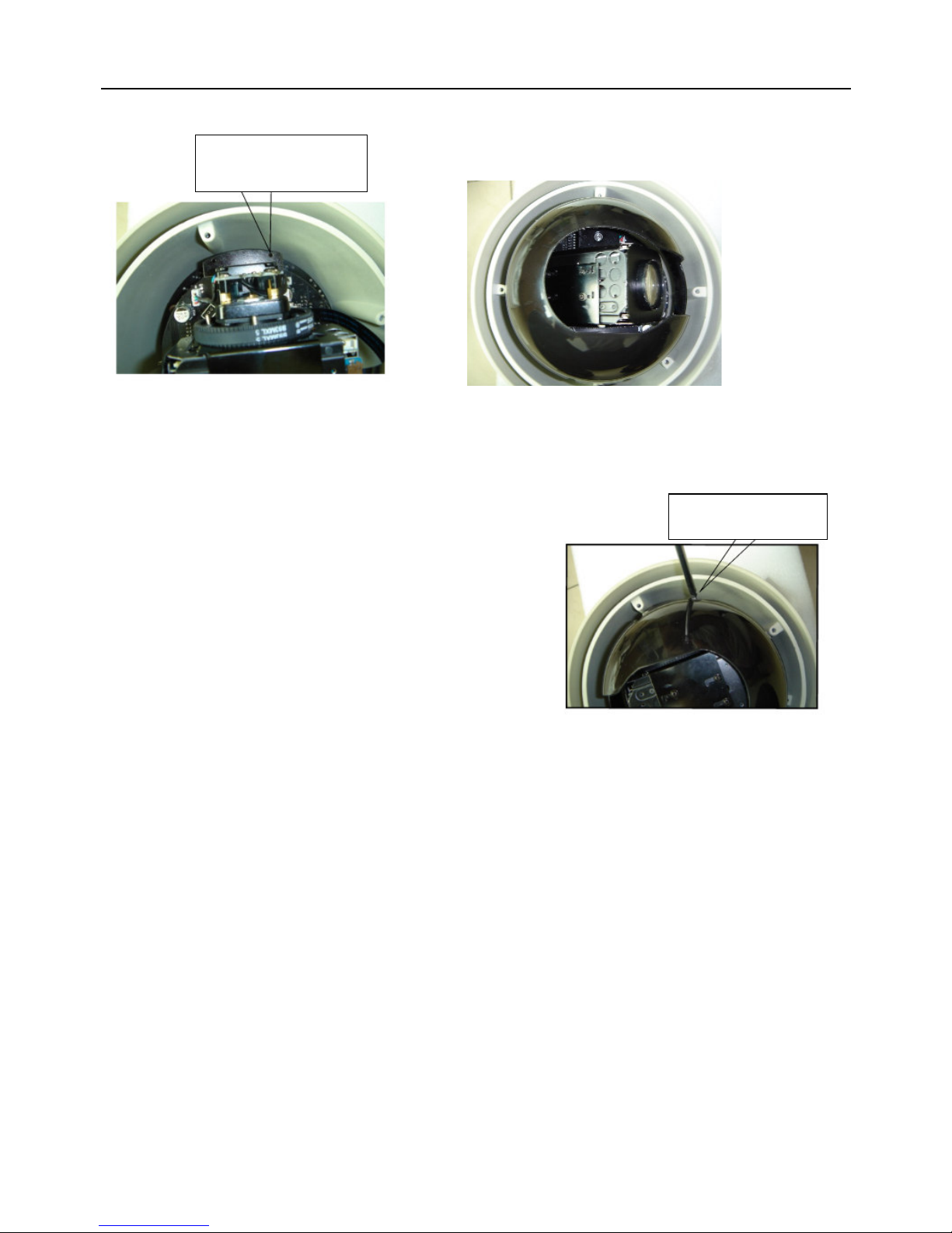
Figure III.1 indicates the fixing holes of acrylic shield, i.e. four M3 screw holes.
Fig. III.1 Fig. III.2
Step one: Aim the open end of shield dome at the lens of camera. Aim the 4 holes on the shield to the 4 M3 screw holes on
the dome device, as indicated in figure III.2.
Step two: screw the four M3 bolt up, as indicated in figure III.3.
Fig. III.3
Fixing holes of shield
dome
Screw the bolts up
Page 7
6
IV. Installation Instruction of the Acrylic Dome Shield
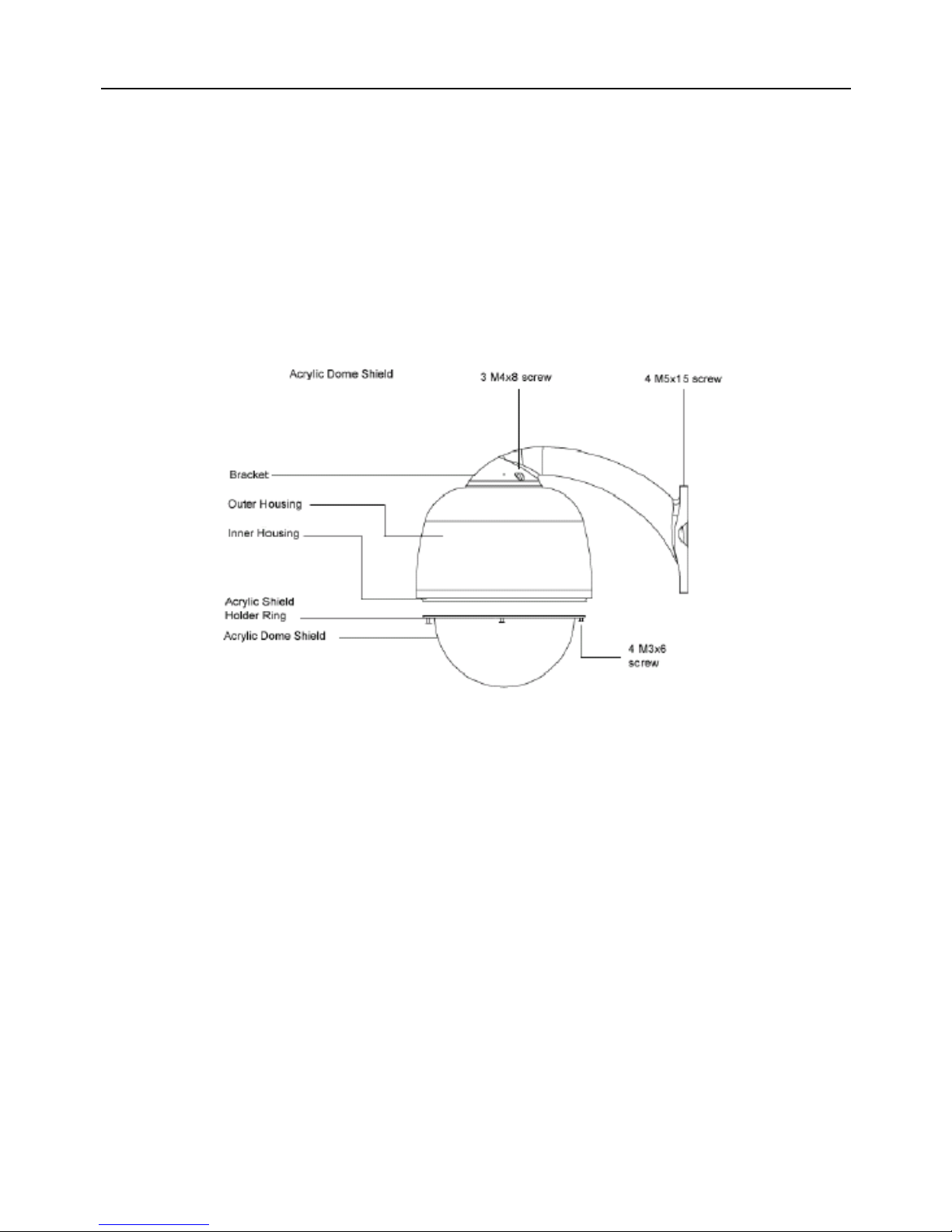
1. Remove Acrylic DOME shield (Please do not scrape the Acrylic shield. It is recommended to wear
cotton gloves when operate).
2. As shown in the figure below, first take the flexible flat cable through connector above the base
plate
and buckle it on the connector. Then buckle the cable on the connection below the CAMERA.
3. Lock the CAMERA up and fix the screws.
4. Install Acrylic shield
Fig IV.1 Installation of the Acrylic Dome Shield
Page 8
7
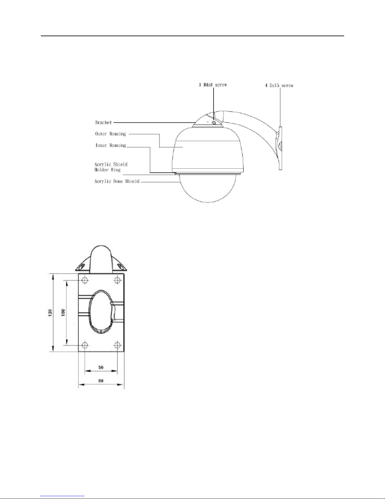
V. Install Bend-Tube-Style Bracket
Fig V.1 Connecting the dome to the wall mount with the bracket.
Fig V.2 Wall mount bracket installation
Page 9
8
Chapter Two Wiring and Setup of Dome System
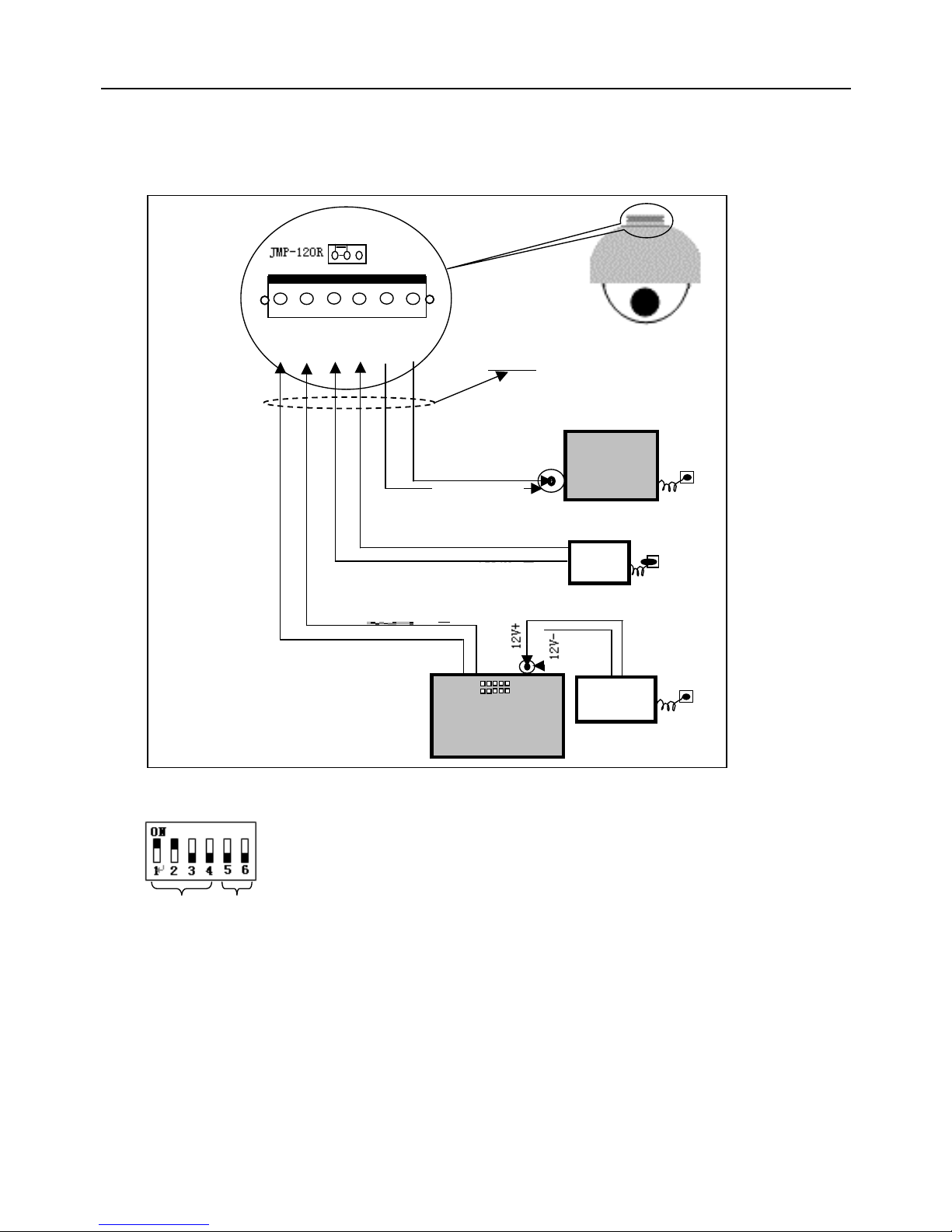
I. Wiring of Dome System
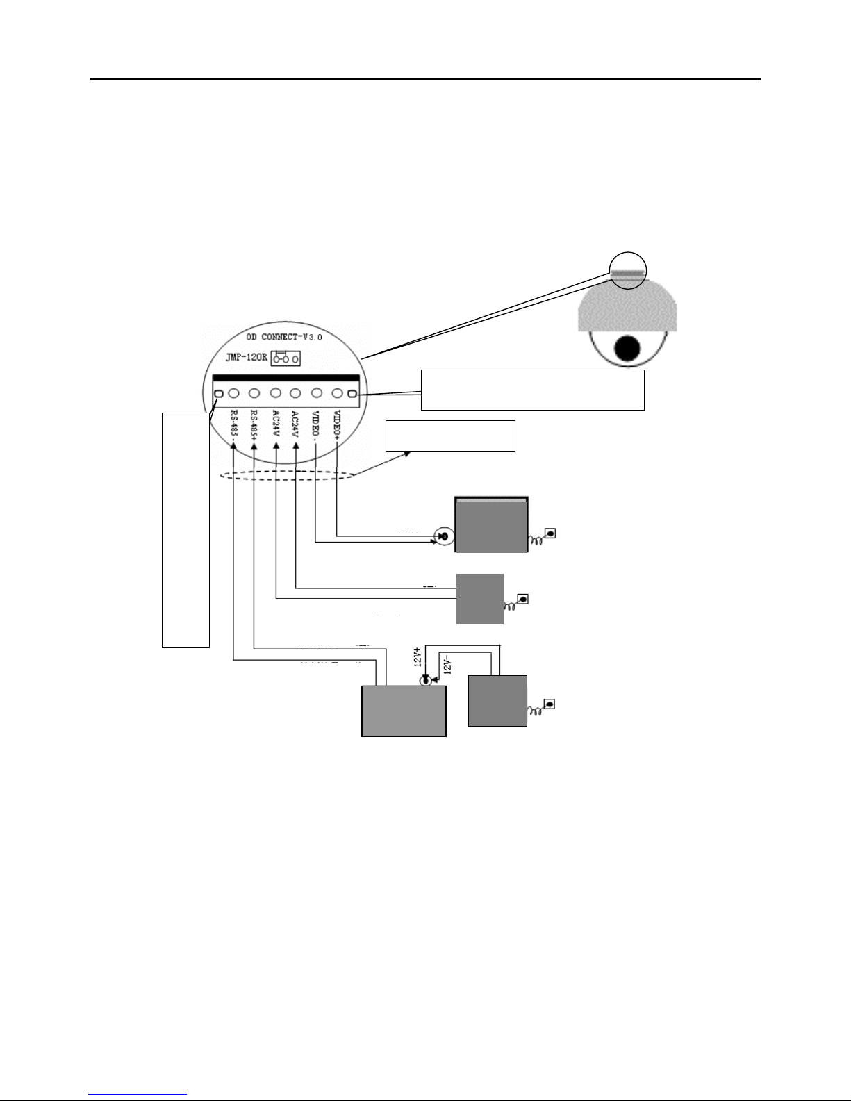
1.Basic system connection.(One dome device)
From the basic system connection, user can understand the electric wiring attribute of the dome device
and bring great operation convenience of installation, testing and demo. When using this product for
the first time, please read carefully and follow this electric wiring drawing as any wrong wiring may lead
to permanent damage of the dome device or damage of other equipment.
In the drawing, JMP-120R is the impedance matching selection of control signal and noise restrain of
RS-485, when there is long distance transmission or noise-control, it can short jumper
!Attention: No operation when the dome device is power on.
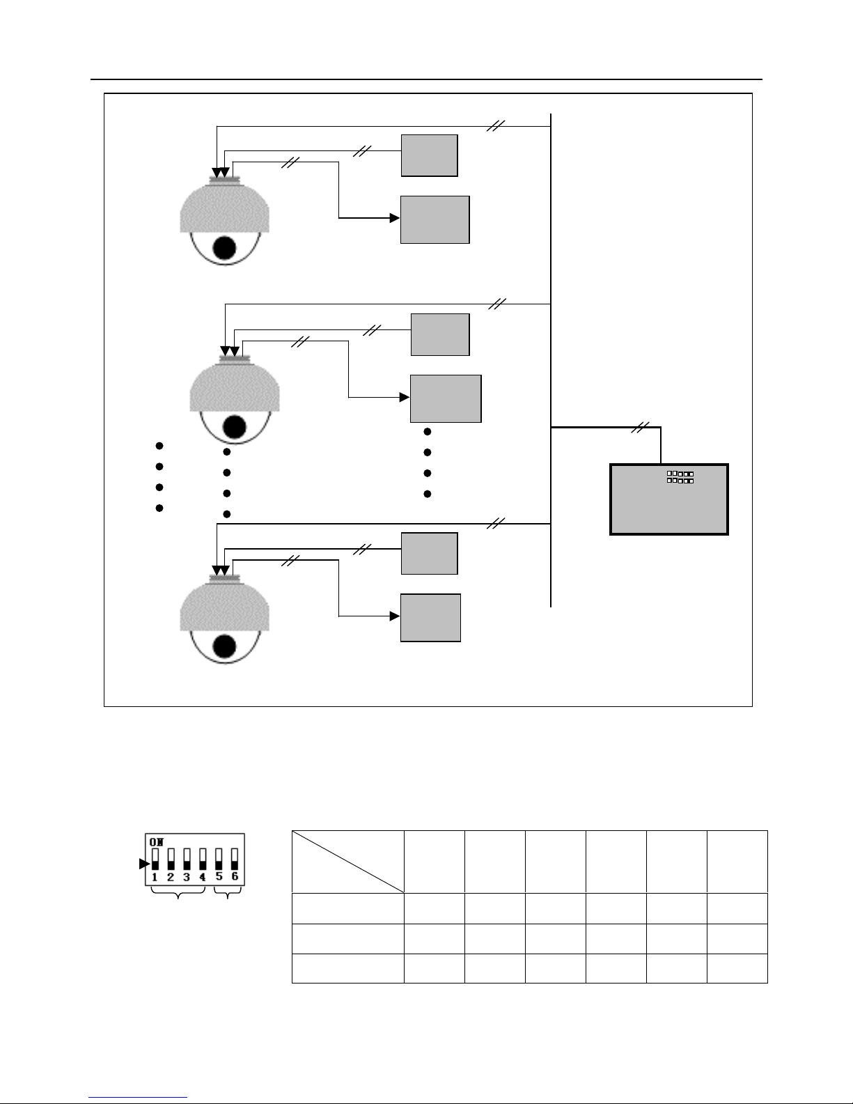
2. Multi-dome device connection.
When connecting many dome devices together, the user can embed multi-device system with
auxiliaries such as arrester device, video matrix, DVR and alarm box for system integration.
AC24V: Power supply of dome device, which will convert 110V/60HZ or 220V/50HZ input to AC 24V
output and supply to the dome device.
RS-485 Bus: It is for the control signal(RS-485 signal) output of controller, connecting to the
communication input terminals of control cable of each dome device.
Video: It is for image signal output of dome device, (can directly output to video equipment such as
monitor or video matrix. Take care of the match up of impedance.)
接大地/试机时可不接
GND/No need when testing
Connecting cable
Video+
GND/No need when testing
Socket of
dome device
Video
-
AC24V (
Red)
AC24V
Control
signal+ (orange)
Control
signal
-
Image
displayer
Dome device
controller
Power
of
dome
device
Power of
keyboard
Page 10
9
II. Setting of Dome Device communication
Before installation and use, the setting of communication protocol and transmission speed (baud rate)
should comply with the control system.
1.Setting protocol and baud rate of dome device.
On/Off
status
Protocol type
1st digit
2nd
digit
3rd
digit
4th digit
5th
digit
6th digit
PELCO-D
ON ON OFF OFF ** **
PELCO-P
OFF OFF ON OFF ** **
TeleEye DM2
ON ON ON OFF ** **
协
议
设
置
波
特
率
设
置
拔
码
开
关
拔
码
开
关
拔
码
开
关
拔
码
开
关
Dome device
controller
Image
displayer
Power
of dome
AC24V
Video
Image
displayer
Power
of dome
AC24V
Video
Image
display
Power
of dome
AC24V
Video
Dome #1
Dome #2
Dome #N
RS-485
RS-485
RS-485
RS-
485 Bus
(Wiring of multi
-
dome)
On/Off switch
Baud rate setting
Protocol setting
Page 11
10
AAttention: the protocol and baud rate of dome device should comply with
those of controller, which need to be restarted after revision.
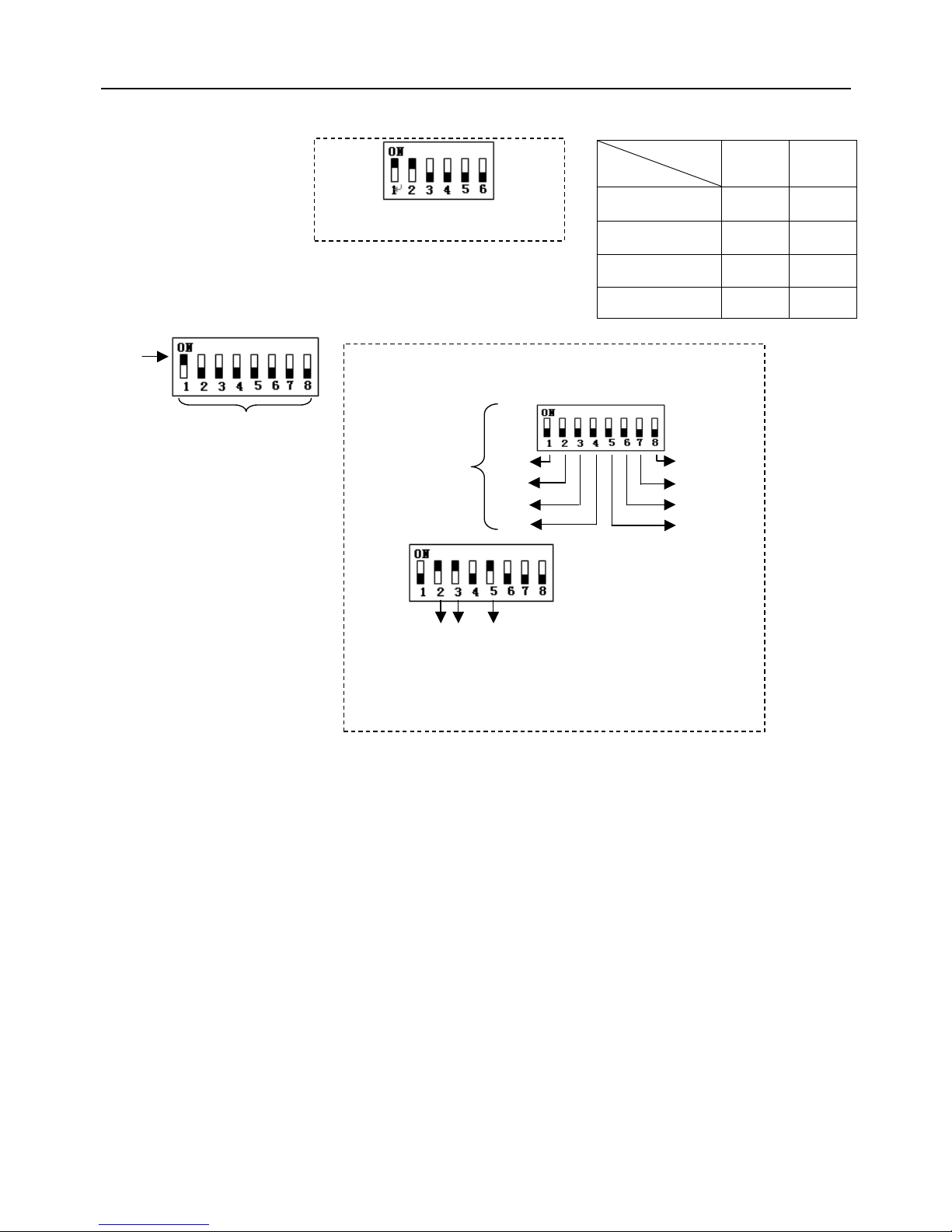
2. Address setting of dome device.
Dome device range: 0~255.
On/Off status
Baud rate
5th digit 6th digit
2400
OFF OFF
4800
OFF ON
9600
ON OFF
19200
ON ON
This figure shows protocol of
PELCO-D, Baud rate of 2400.
Setting address for dome
device (this figure shows the
address of dome device No
1).
On/Off switch
Setting method: The sum of switch numbers when it is at ON
position is the address of dome device.
Calculation example of dome device address:
1
2
4
8
16
32
64
128
Matching numbers
2
4
16
(2+4+16=22)the address is 22.
On/off
switch and
matching
Page 12
11
Page 13
12
Chapter Three Fast Operation Guide of Dome Device
I. Wiring (Please do not turn the power on).
II. Setting protocol and baud rate. (Turn the power off when setting, and restart the device after revision).
\
The figure shows: Protocol: PELCO-D
Baud rate: 2400 bps
(Please refer to detailed parameter in next chapter)
This dip switch located on PCB in the dome device
Protocol setting
Baud rate setting
Image
displayer
Cables
RS
-
485
-
RS
-
485+
AC24V AC24V
VIDEO
-
VIDEO
+
Keyboard
power
Keyboard of
controller
Dome
power
OD CONNECT-V3
Groundi
ng
Grounding
Socket
of
dome
device
Video+
Video-
AC24V (
Red)
AC24V (Black)
Con
trol signal
-
Control signal+
Page 14
13
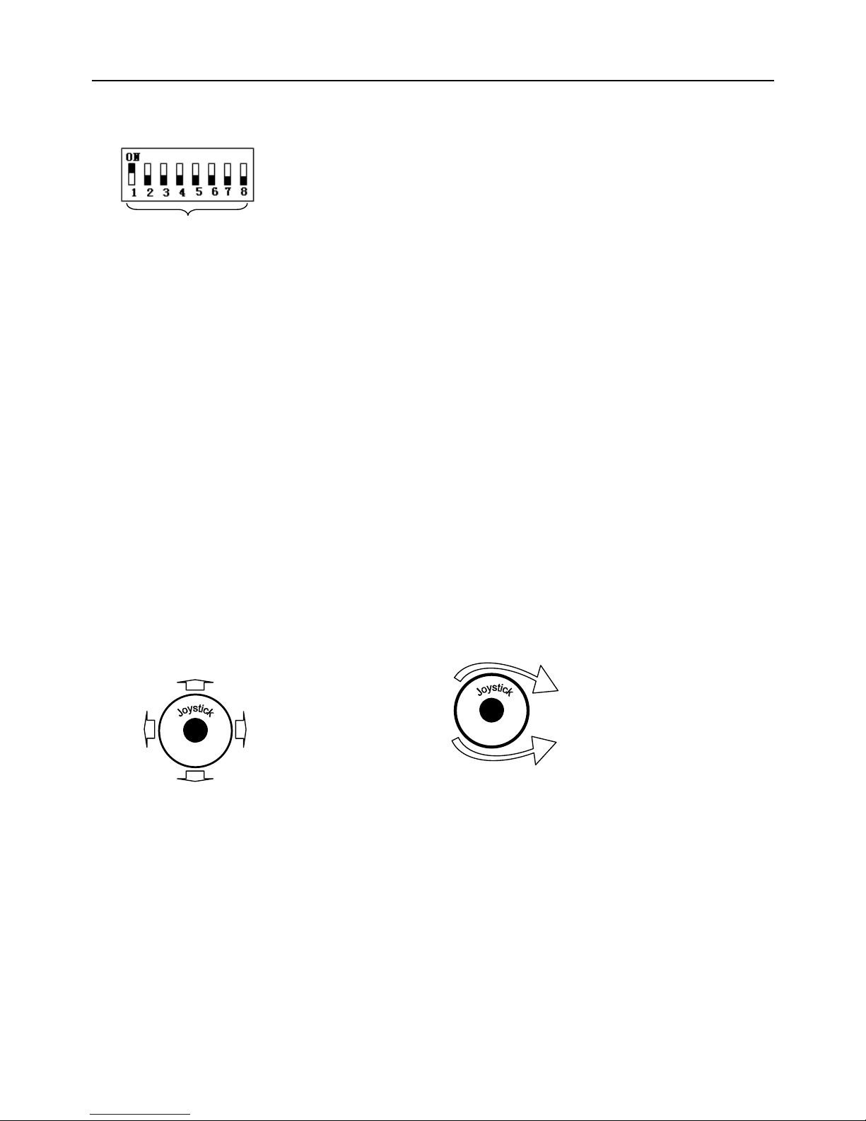
III. Setting dome device address. (Turn the power off when setting, and restart the device after revision).
The figure shows: Address of the dome device: No. 1
(Please refer to detailed parameter in next chapter)
This dip switch located on PCB in the dome device
IV. Install camera. (Please refer to camera installation for details).
Attention: 1. Do not connect the camera and dome device with FFC in a wrong way.
2. The installation holes of different camera differ.
V. Connect the power of dome device.
At this moment, the self-test (rotation) of dome device and self-test (there will be image on the monitor) of camera can be
seen.
Attention: When the dome device is self-testing, it is normal when sound is issued caused by the block of dome device after
2~5 seconds of vertical movement, which is the tilt orientation of the dome itself.
VI. Controller setting.
Set the protocol, baud rate and address of the keyboard controller identical with those of dome device. (Please refer
to keyboard controller instruction manual).
Attention: If the setting of protocol of dome device is auto detection, the protocol of keyboard controller can be set arbitrarily.
But its baud rate should be set identical with that of the dome device.
VII. Start testing.
When all the above are ready, the testing to dome device can be started.
1. Direction control test of dome device 2. Zooming control test of camera
The directions (up, down, left and right) of the Zooming of the camera can be controlled by
dome device can be controlled by using the zooming function Joystick or by using TELE (zoom in)
keyboard controller, as indicated in the figure. and WIDE (zoon out) on the keyboard button.
Note: the working of dome device is normal Note: The camera and dome device are normal
(Please refer to the next section for demonstration of menu operation and control of dome device.)
VIII. Complete the test. (Summary).
1. If the performance of item 7 is normal, it indicates the system is basically normal. Please do not change the wiring and
various setting to avoid fault and unnecessary damage and loss.
2. If the performance of item 7 is abnormal, or only one item works normally, please check the wiring (item 1 and 4) and
setting (item 2, 3 and 6) carefully.
Set address for dome
up
down
Left
right
Zoom in
Zoom
out
Rotate
Page 15
14
Chapter Four -English Operation Menu of Dome Device
I. Main menu
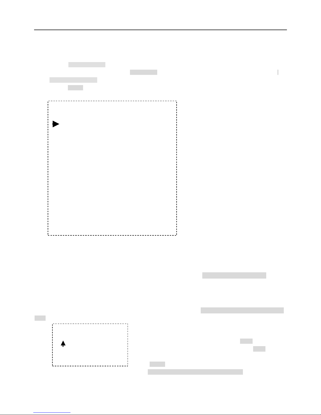
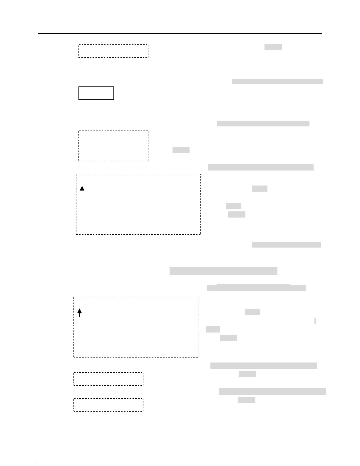
<1>. Press CALL+90+ENTER on the keyboard to enter the main menu of dome device (fig.1).
<2>. Select options Joy stick only between up and down, the arrow points to the current selected option. Press OPEN or
left or right of Joystick to command entering the submenu of that option or change the value or setting of that option.
<3>. Press CLOSE to exit menu or return to upper stage menu.
II. Tree Menu List.
<1>.All sub-menus can be seen clearly in this tree list.
1.Language English <<Language options
2.Display options <<Display options
1.Preshot setup <<Preshot setup options
1.Numder 1 <<Preshot number selection Press OPEN or Joy stick left or right to
enter
<<The default number after entering is 001. (hundred bit/ten bit/single bit). Joy
stick left or right to select preshot position and press OPEN to confirm, and
Joy stick left or right again to select numbers (0~~9). Press OPEN to confirm
the selection.
Press CLOSE to exit or return to upper stage menu when programming is
done. Press OPEN or Joy stick left or right to enter
- - - - - - - - - Fuga6 - - - - - - - - -
1.Language English
2.Display options
3.Control Options
4.Diagnostic Options
5.Camera Options
6.Function Programming
IRIS CLOSE to Exit
<<Language options
<<Display options
<< Control options
<< Diagnostic options
<< Camera options
<<Functions programming
[View1]
1~165
001
0 1 2 3 4 5 6 7 8 9
IRIS CLOSE When Done
Joystick left or right to select
Page 16
15
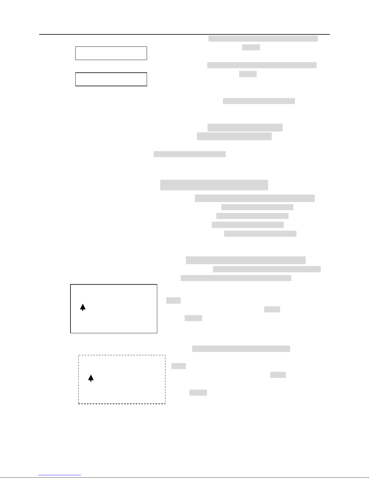
2.Set Preshot <<Set preshot
Select preshot and press CLOSE to confirm the
programming when done and auto exit and return to the
upper stage menu.
3.Call Preshot <<Call preshot.
The action of the dome device can be seen and return
to corresponding preshot point.
4.Delete preshot <<Delete preshot.
<<Reminder: Are you sure to delete preshot?
Press OPEN to confirm
Press CLOSE to exit and return to upper stage menu.
5.Name _ _ _ _ _ _ _ _ <<Edit the name of preshot. Press OPEN or Joy stick left or right to enter
6.Name Display ON/OFF <<Name display On/Off
IRIS CLOSE to Exit
2.Sector Setup <<Sector setup Press OPEN or Joy stick left or right to enter
1.Number ( 1 ~ 9 ) <<Number selection
2.Name _ _ _ _ _ _ _ _ <<Name editing
3.Pan Start pos 0.0
4.Pan End pos 0.0
IRIS CLOSE When Done
Call out
Are you sure to do this?
IRIS OPEN to Confirm
IRIS CLOSE to Cancel
_ _ _ _ _ _ _ _
0 1 2 3 4 5 6 7 8 9
A B C D E F G H I J K L M N
O P Q R S T U V W X Y Z _
IRIS CLOSE When Done
_ _ _ _ _ _ _ _
0 1 2 3 4 5 6 7 8 9 A B C D E F G H I J K L
M N
O P Q R S T U V W X Y Z _
IRIS CLOSE When Done
IRIS CLOSE When Done
IRIS CLOSE When Done
Press OPEN or joystick left or right to enter
Press OPEN or Joystick left or right to enter
<<Joystick left or right when
programming to select
preshot and press OPEN to confirm.
Joystick left or right to select (0~~9 or A~~Z).
Press OPEN to confirm selection.
Press CLOSE
to exit or return to upper stage
menu when programming is done.
<< Joy stick left or right when programming to select
preshot and press OPEN to confirm.
Joy stick left or right to select (0~9 or A~Z). Press
OPEN to confirm selection.
Press CLOSE
to exit or return to upper stage menu
when programming is done.
Joystick left or right to select
Joy stick left or right to select
Press OPEN or Joy stick left or right to
<<Setup pan start point. Press OPEN or Joy stick left or right to enter
Capture the start point and press CLOSE
to exit and return to upper stage
menu.
<< Setup pan end point. Press OPEN or Joy stick left or right to enter
Capture the end point and press CLOSE
to exit and return to upper stage
menu.
Page 17
16
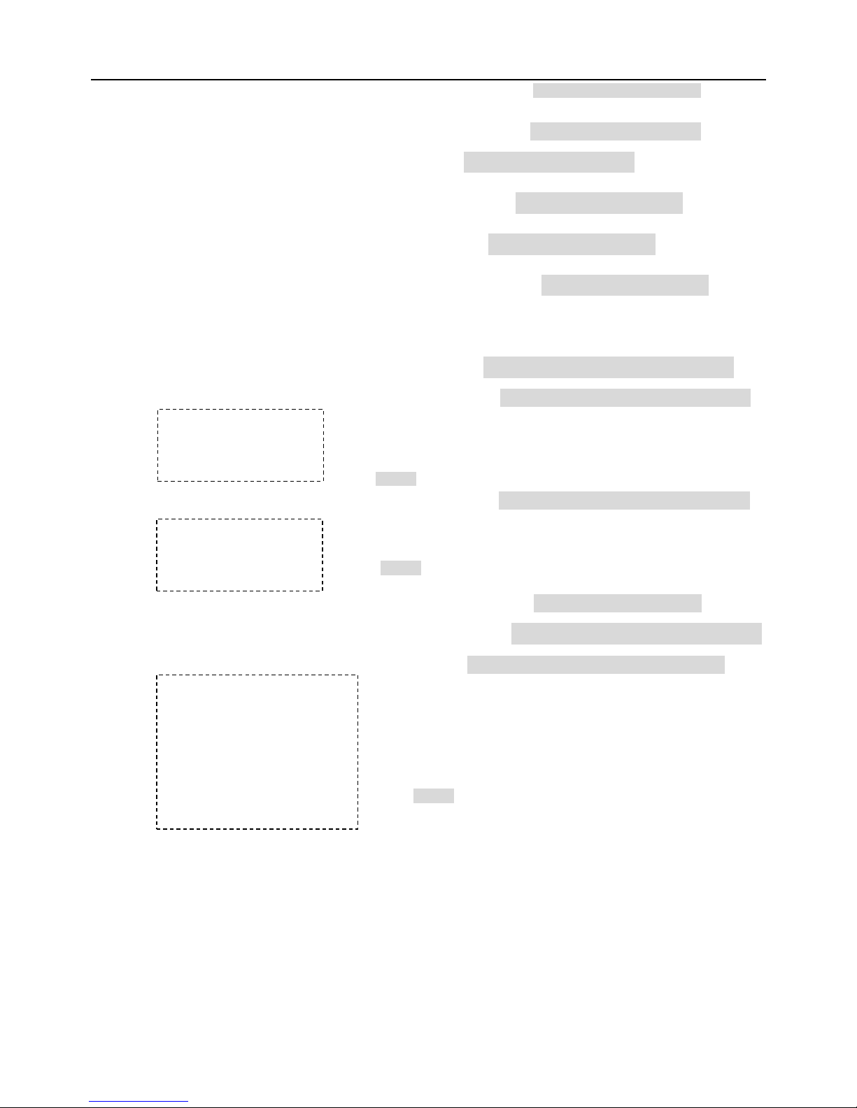
5.Tilt Start pos 0.0
6.Tilt End pos 0.0
7.Name display ON/OFF <<Sector name display On/Off Joy stick left or right to select
IRIS CLOSE to Exit
3.Coordinates ON/OFF <<Coordinates display On/Off Joy stick left or right to select
4.Crosshairs ON/OFF <<Crosshairs On/Off Joy stick left or right to select
5.Start-UP scr msg ON/OFF <<Start-up screen message display On/Off
Joy stick left or right to select
IRIS CLOSE to Exit
3.Control options <<Control options Press OPEN or Joy stick left or right to enter
1.Set pan and Tilt <<Pan/Tilt setup of dome device Press OPEN or Joy stick left or right to enter
1.Pan Reverse ON/OFF << Pan Reverse ON/OFF Joy stick left or right to select
2.Tilt Reverse ON/OFF << Tilt Reverse ON/OFF Joy stick left or right to select
3. +2 Tilt Limit ON/OFF <<+2 Tilt Limit ON/OFF Joy stick left or right to select
4.Find Home on STA ON/OFF << Find Home on start ON/OFF Joy stick left or right to select
IRIS CLOSE to Exit
2.Set Default Function <<Set default function Press OPEN or Joy stick left or right to enter
1.Default Function P/V/T <<Select default function (Preshot/Tour/PTZ) Press OPEN or Joy stick left or right to enter
2.Number 1 << Function number selection Press OPEN or Joy stick left or right to enter
3.Delay 001 <<Time delay setting (second) Press OPEN or Joy stick left or right to enter
IRIS CLOSE When Done
IRIS CLOSE When Done
1~128
001
0 1 2 3 4 5 6 7 8 9
IRIS CLOSE When Done
1~999
001
0 1 2 3 4 5 6 7 8 9
IRIS CLOSE When Done
<< Setup tilt start point. Press OPEN or Joy stick left or right to enter
Capture the start point and press CLOSE
to exit and return to upper stage
menu.
<< Setup tilt end point. Press OPEN or Joy stick left or right to enter
Capture the end point and press CLOSE
to exit and return to upper stage
menu.
<< Joy stick left o
r right when programming to select preshot and press
OPEN to confirm.
Joy stick left or right to select (0~~9). Press OPEN to confirm selection
.
Press CLOSE
to exit or return to upper stage menu when
programming is done.
<< Joy stick left or right when programming to select preshot and press
OPEN to confirm.
Joy stick left or right to select (0~~9). Press OPEN to confirm
selection.
Press CLOSE
to exit or return to upper stage menu when
programming is done.
Page 18
17
4.Operation ON/OFF <<Default function On/Off Joy stick left or right to select
IRIS CLOSE Exit
3.Speed Limit ON/OFF <<Operation speed limit On/Off Joy stick left or right to select
4.Auto Flip ON/OFF <<Auto flip On/Off Joy stick left or right to select
5.Auto Focus PTZ/OFF/Z <<Auto focus options Joy stick left or right to select
6.Auto AE PTZ/OFF/Z <<Auto AE option Joy stick left or right to select
7.Vector scan AF ON/OFF <<Vector scan auto focus control Joy stick left or right to select
IRIS CLOSE to Exit
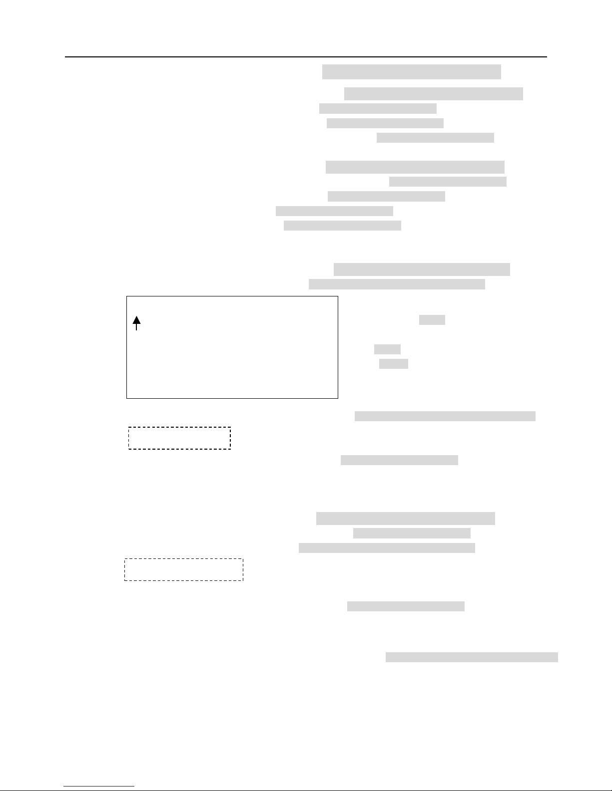
4.Diagnostic Options <<Diagnostic options Press OPEN or Joy stick left or right to enter
1.Clear Memory <<Clear data in the memory Press OPEN or Joy stick left or right to enter
2.Restore Def Setting <<Restore default setting Press OPEN or Joy stick left or right to enter
3.Color system PAL/NTSC << PAL/NTSC switch Joy stick left or right to select
4.Scan & Camera Reset(Null) <<Restart dome camera.Press OPEN or Joy stick left or right to enter
5.Dome Information <<Dome information. Press OPEN or Joy stick left or right to enter
IRIS CLOSE to Exit
Are you sure to do this?
IRIS OPEN to Confirm
IRIS CLOSE to Cancel
Are you sure to do this?
IRIS OPEN to Confirm
IRIS CLOSE to Cancel
----------------FuGa6---------------
Camera:x x x x x x x x
Protocol:x x x x x x x x
Baud rate: x x x x
Dome No.:x x x
IRIS CLOSE to Exit
<<Reminder: are you sure to do this.
Press OPEN to confirm.
Press CLOSE to exit and return to upper stage menu.
<< Reminder: are you sure to do this.
Press OPEN to confirm.
Press CLOSE to exit and return to upper stage menu.
<<Name of dome
<<Type of camera
<<Control protocol
<<Baud rate
<<Dome number
<< Press CLOSE to exit and return to upper stage menu.
Page 19
18
5.Camera Options << Camera options Press OPEN or Joy stick left or right to enter
1.Zoom and Focus << Zoom and focus setting Press OPEN or Joy stick left or right to enter
1.Zoom Speed ( 0~8 ) <<Zoom speed setting. Joystick left or right to select
2.Digital Zoom ON/OFF <<Digital zoom in On/Off Joystick left or right to select
3.AF Sensitivity High/Low <<Auto focus sensitivity setting. High/Low Joystick left or right to select
IRIS CLOSE to Exit
2.Auto Exposure << Auto exposure setting. Press OPEN or Joy stick left or right to enter
1.AE Mode Auto/Manual/shutter/Iris <<Auto exposure mode selection. Joystick left or right to select
2.shutter Speed xx <<Shutter speed setting. Joystick left or right to select
3.Iris Fxx <<Iris setting. Joystick left or right to select
4.Gain x <<Gain setting. Joystick left or right to select
IRIS CLOSE to Exit
3.Camera Name <<Camera name setting Press OPEN or Joystick left or right to enter
1.Name _ _ _ _ _ _ _ _ <<Edit camera name Press OPEN or Joystick left or right to enter
2.Change Name Loc <<Change display location of name. Press OPEN or Joystick left or right to enter
3.Name Display ON/OFF <<Name display On/Off Joystick left or right to select
IRIS CLOSE to Exit
4.Mask Setting <<Mask sector setting Press OPEN or Joy stick left or right to enter
1.Numder ( 1 ~~ 8 ) <<Mask sector number selection. Joystick left or right to select
2.Mask Edit <<Mask editing Press OPEN or Joystick left or right to enter
3.Mask Display ON/OFF << Mask Display ON/OFF Joystick left or right to select
IRIS CLOSE to Exit
5.WB Mode Auto/Manual/Indoor/Outdoor/Onepush/Taw <<White balance mode options
_ _ _ _ _ _ _ _
0 1 2 3 4 5 6 7 8 9 A B C D E F G H I J K L M N O P Q
R S T U V W X Y Z _
IRIS CLOSE When Done
IRIS CLOSE to Exit
IRIS CLOSE When Done
<< Joy st
ick left or right when programming to select
preshot and press OPEN to confirm.
Joy stick left or right to select (0~~9 or A~~Z).
Press OPEN to confirm selection.
Press CLOSE
to exit or return to upper stage
menu when programming is done.
<<Joy stick arbitrarily and the display will be changed on the screen.
<<Capture the masking point, press CLOSE to confirm. The system
will auto exit
and return to upper stage menu.
Press OPEN or Joystick left or right to
Page 20
19
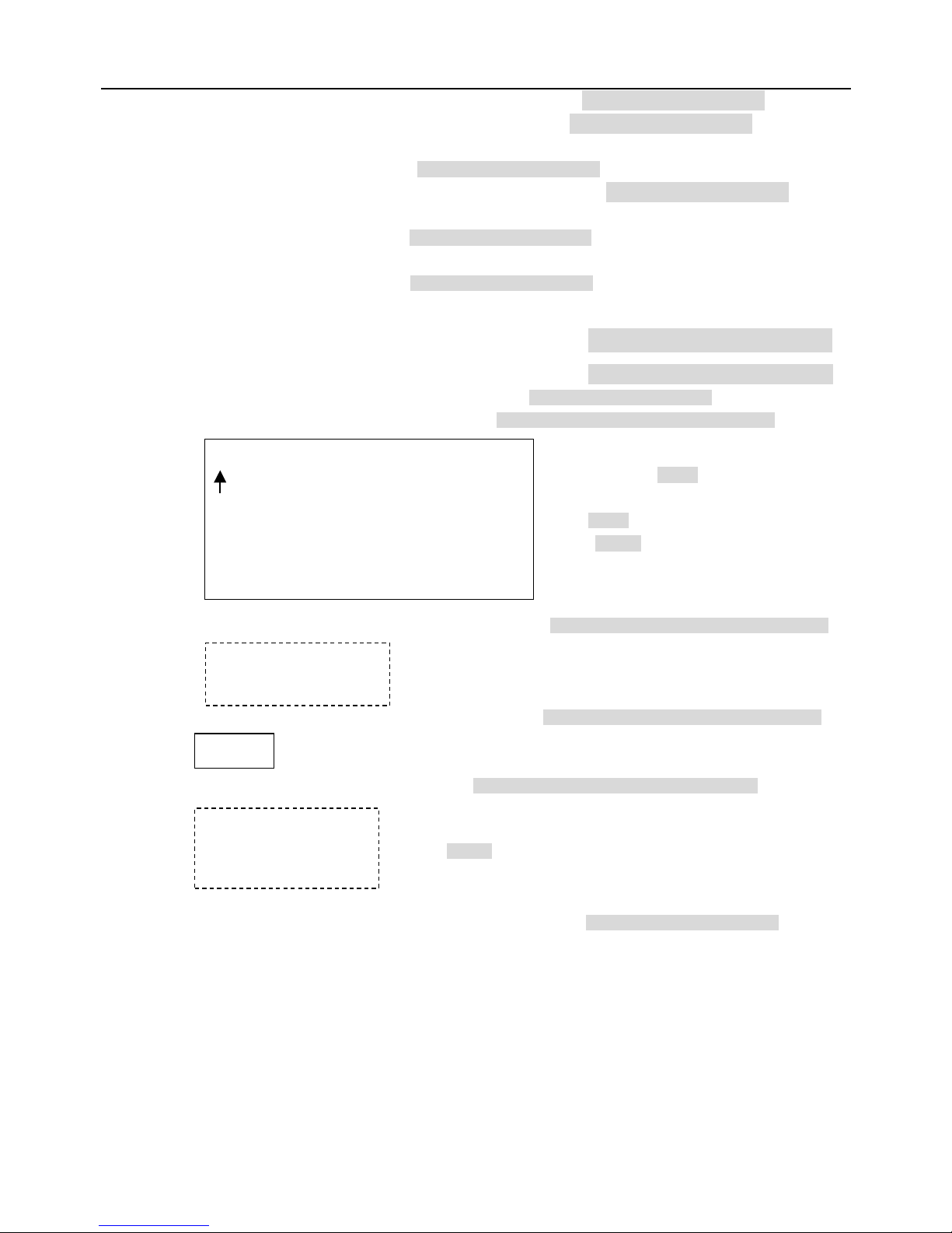
6.Back Light ON/OFF <<Back light On/Off Joystick left or right to select
7.Picture Flip ON/OFF <<Picture flip On/Off Joystick left or right to select
8.Picture LR Rev ON/OFF <<Picture left and right reverse On/Off
Joystick left or right to select
9.Picture Stable ON/OFF <<Picture stabilized On/Off Joystick left or right to select
10.Day/Night ON/OFF <<Black/white and color switch On/Off
Joystick left or right to select
11. F-OSD ON/OFF <<Camera function display On/Off
Joystick left or right to select
IRIS CLOSE to Exit
6.Function Programming <<Special function programming Press OPEN or Joystick left or right to enter
1.PTZ Tour (Pattern) <<Pan/Tilt/Zoom tour programming Press OPEN or Joystick left or right to enter
1.Number ( 1 ~~ 3 ) <<PTZ tour number Joystick left or right to select
2.Name _ _ _ _ _ _ _ _ <<Edit PTZ name Press OPEN or Joy stick left or right to enter
3.Program a Tour <<Enter PTZ tour programming Press OPEN or Joy stick left or right to enter
4.Run a Tour <<Run Pan/Tilt/Zoom tour (pattern) Press OPEN or Joy stick left or right to enter
5.Delete a Tour <<Delete PTZ tour. Press OPEN or Joy stick left or right to enter
6. Name Display ON/OFF <<PTZ tour name display On/Off Joy stick left or right to select
IRIS CLOSE to Exit
_ _ _ _ _ _ _ _
0 1 2 3 4 5 6 7 8 9 A B C D E F G H I J K L M N O P Q
R S T U V W X Y Z _
IRIS CLOSE When Done
IRIS OPEN to Begin
IRIS CLOSE to Exit
Call out
Are you sure to do this?
IRIS OPEN to Confirm
IRIS CLOSE to Cancel
<<
Joystick left or right when programming to select
preshot and press OPEN to confirm.
Joystick left or right to select (0~~9 or A~~Z).
Press OPEN to confirm selection.
Press CLOSE to e
xit or return to upper stage
menu when programming is done.
<<Press OPEN to confirm and start programming.
<<Press CLOSE to exit the programming and return to upper stage menu.
<< Reminder: are you sure to do this.Press OPEN to confirm.
Press CLOSE to exit and return to upper stage menu.
Page 21
20
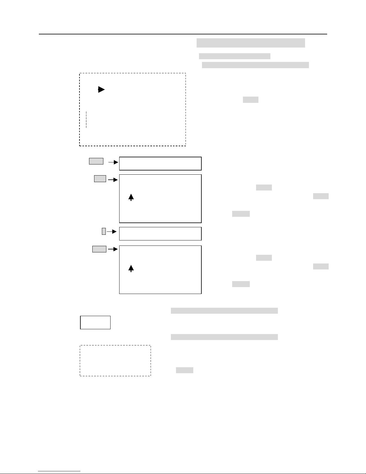
2.Program Vector Scan << Program vector scan. Press OPEN or Joy stick left or right to enter
1.Number ( 1 ~~ 6 ) <<Vector scan number Joy stick left or right to select
2.Program a Vector scan <<Vector scan programming Press OPEN or Joy stick left or right to enter
3.Run a Vector Scan <<Run vector scan. Press OPEN or Joy stick left or right to enter
4.Delete a Vector Scan <<Delete vector scan Press OPEN or Joy stick left or right to enter
IRIS CLOSE to Exit
Call out
Are you sure to do this?
IRIS OPEN to Confirm
IRIS CLOSE to Cancel
<< Reminder: are you sure to do this.
Press OPEN to confirm.
Press CLOSE
to exit and return to upper stage
Name Num V Dwell
1 _ _ _ _
2 _ _ _ _
3 _ _ _ _
16
IRIS CLOSE When Done
<<Joystick arbitrarily to move the
cursor, and stop the cursor at place
of programming. Press OPEN to
enter the selection.
<<Press OPEN continuously to select
P: Preshot, T:
self-study, V: vector scan
<< Joy stick left or right when programming to select
preshot and press OPEN to confirm.
Joy stick left or right to select (0~~9). Press
OPEN
to confirm selection.
Press CLOSE
to exit or return to upper stage
<< Press OPEN continuously to select
<< Joy stick left or right when programming to select
preshot and press OPEN to confirm.
Joy stick left or right to select (0~~9). Press
OPEN
to confirm selection.
Press CLOSE to exit
or return to upper stage
menu when programming is done.
1~99
001
0 1 2 3 4 5 6 7 8 9
IRIS CLOSE When Done
1~128
001
0 1 2 3 4 5 6 7 8 9
IRIS CLOSE When Done
1~9
P/T/V
Name
Num
V
Dwell
Function name
Function number
Velocity selection
Dwell time
Page 22
21
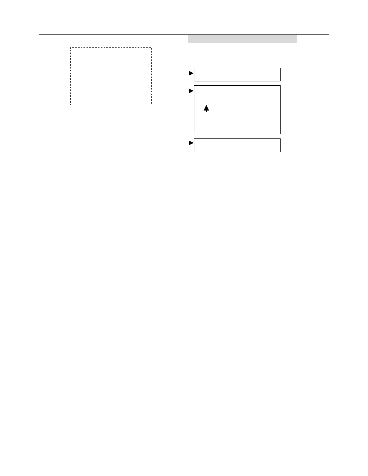
3.Program Alarms <<Program alarms. Press OPEN or Joystick left or right to enter
<<This function is not available at the moment.
Name Num E/N
1 _ _ _
2 _ _ _
3 _ _ _
4 _ _ _
IRIS CLOSE to Exit
P/V/T
1~128
0
0 1 2 3 4 5 6 7 8 9
IRIS CLOSE When Done
N/Y
Name
Num
E/N
Page 23
22
Chapter Five Coding description of protocol and serial transmission rate
When setting communication protocol of the Dome device (first 4 bits of SW2) and default serial
transmission rate of the protocol (last 2 bits of SW2), if default serial transmission rate of the protocol
does not match with serial transmission rate of host, please set the default serial transmission rate of the
protocol consistent with the default serial transmission rate of host according to Chapter two II.
Operation Key
Set Preset Point
PRESET(hold 2 sec) + N + ENTER(+N+Enter+N+Enter+…)+SET
1) Press and hold PRESET key for 2 seconds.
2) Adjust the camera to the desired direction and focus.
3) Input the preset number.
4) Press ENTER.
5) Repeat step 2 to step 4 if you want to set more preset point.
6) Press set key to exit
Call Preset
N + PRESET
1) Input the preset number
2) Press ENTER
Set Home Position
T + DWELL + N + PRESET
1) Input a number T(a value between 1 and 255). T represents the
time between stoping operation to the camera and the camera’s
automatically turning back to the home position.
2) Press DWELL.
3) Input a preset number which you want to be your home position.
4) Press PRESET.
Delete Home Position
0 + DWELL + 0 + PRESET
Set Preset Tour Sequence
TOUR(hold 2 sec) + S + Enter + N + Enter(+N+Enter+N+Enter+… )+
Set
1) Press and hold TOUR for 2 seconds.
2) Input the sequence number(from 1 to 4)
3) Press ENTER.
4) Input the preset number representing the first tour point.
5) Press ENTER.
6) Repeat step 2 and step 3 for other tour point.
7) Press SET to exit.
Page 24

23
Activate Preset Tour
T + DWELL + S + TOUR
1) Input a number T, where T represent how much second the camera
rest on one tour point before it move to another tour point.
2) Press DWELL.
3) Input S where S is the tour sequence number
4) Press TOUR.
Delete Preset Tour
TOUR + S + DEL
1) Press TOUR.
2) Input the number S where S represents the tour sequence number.
3) Press DELETE.
Auto Pan
SCAN + 0 + ENTER : Set auto pan left limit
SCAN + 1 + ENTER : Set auto pan right limit
S + SCAN : Activate auto pan.
If S is within 1 – 80, the scan rate is slow.
If S is within 81-160, the scan rate is medium.
If S is within 161-250, the scan rate is high.
Focus Control
Generally the camera will automatically adjust the focus to get clearer
image based
on the distance of the camera.
But you can manually adjust the focus by pressing FAR, NEAR as you wish.
The camera will switch back to automatically when you conduct other operations
such as moving the joystick.
Iris Control
Generally the camera will automatically adjust the iris to get clearer image based
on the illumination.
But you can manually adjust the iris by pressing OPEN, CLOSE as you wish.
The camera will switch back to automatically when you conduct other operations
such as moving the joystick.
Page 25
24
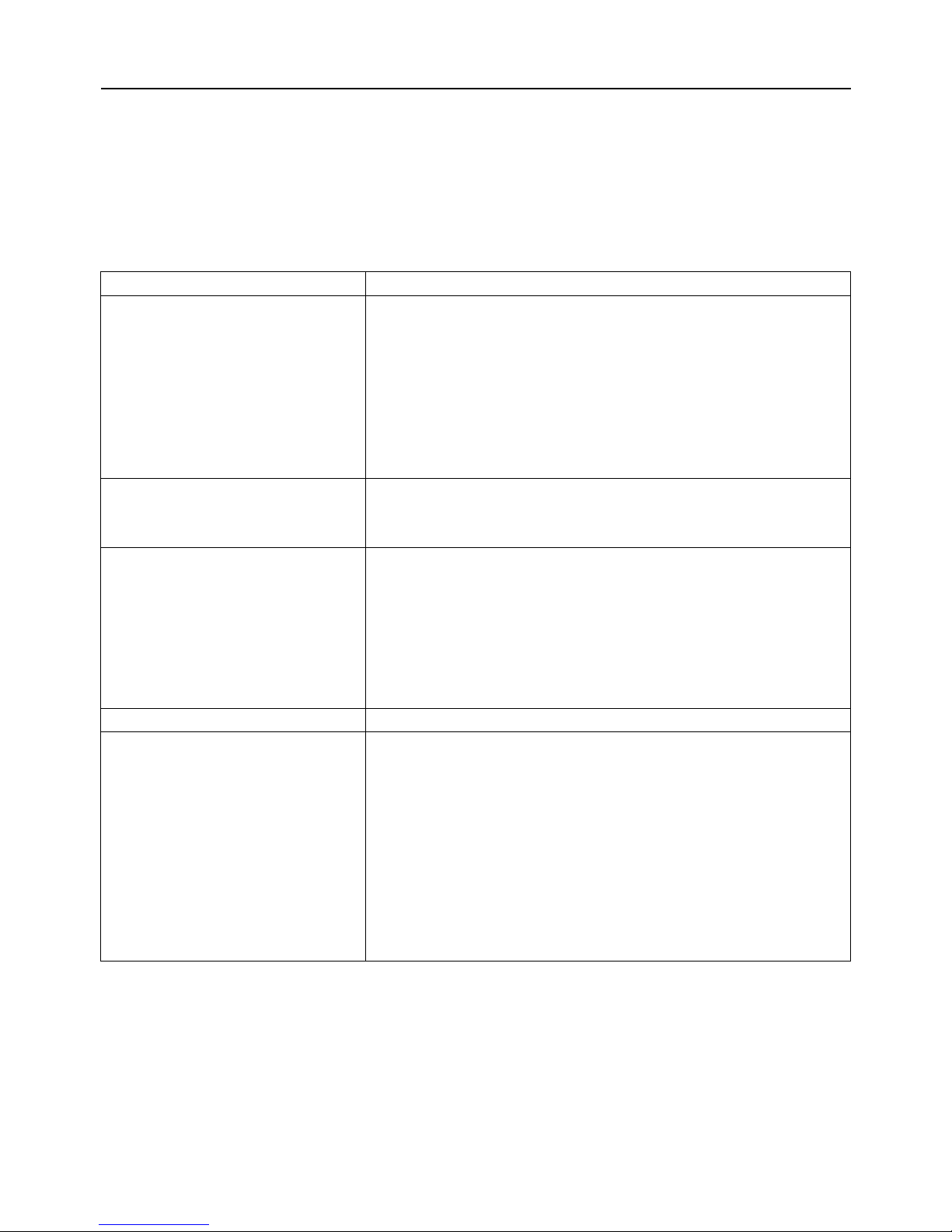
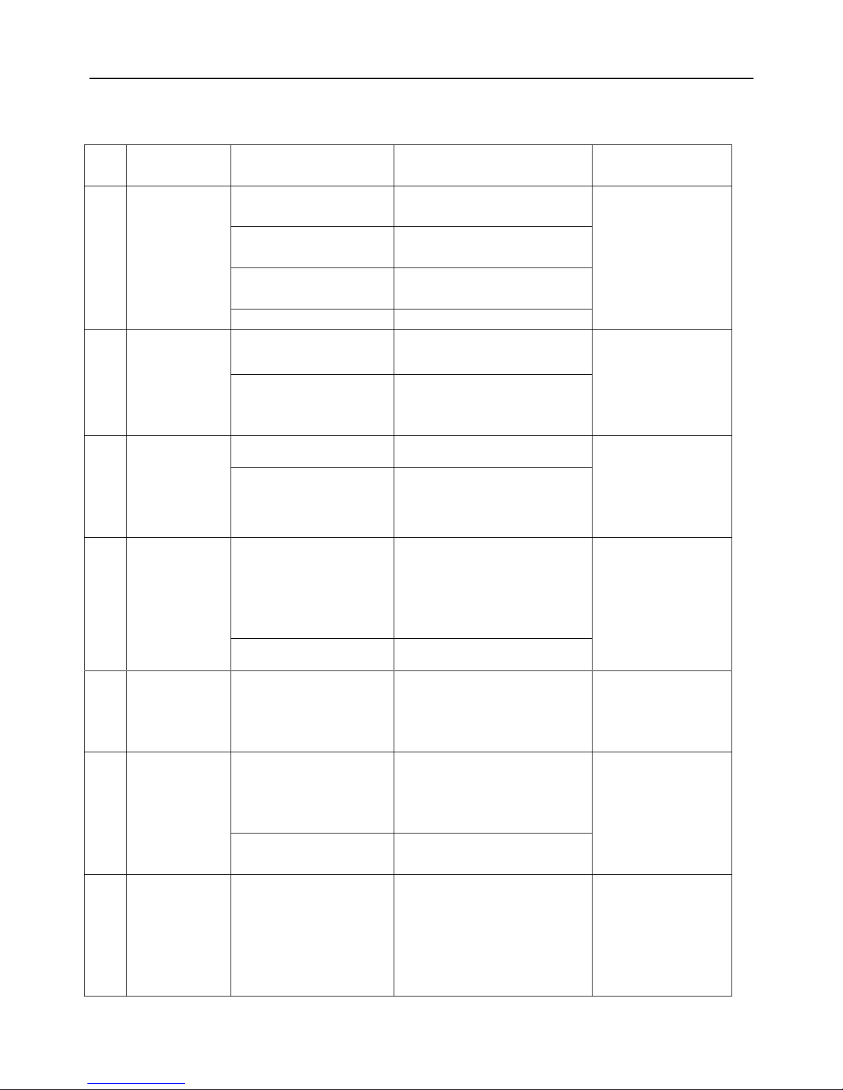
Chapter Six Trouble Shooting of Dome Device
S.N.
Problem
Description
Possible Reason Troubleshooting Remarks
Power cable is connected
improperly.
Check if the power cable is
connected to power of AC24V
Fault of power PCB of dome
device
Change the power PCB
slip ring power wires
disconnected
Change slip ring
1
After power on,
no motion and no
image.
Fault of main control board Change main control board
Please follow the above
basic system wiring
strictly
Character monitor switch is
off
Switch on the character monitor
according to the menu instruction
2
After power on,
the dome device
rotate normally,
but no character
nor image display
Improper connection
between camera and dome
device
Replace a FFC cable or a camera
About 45 second after
the dome device is
power on.
wrong operation CALL+90+ENTER open
3
After self-test of
the dome
device, menu
cannot be
displayed
Fault of OSD control board Change OSD board
After self-test, the menu
can only be displayed
when there is image
display of the dome
device
Interfered by exterior
electronic signal (noise) or
the camera is directed to
the monitor screen
Grounding the dome device or shut
off the surrounding big electronic
devices(electric, HF, signal
generating) equipment, or rotate
the camera
4
Distorted
character or
image
System wrong function Restart the dome device
Shielded cable should
be adopted for video
cable
5
After power on,
no self-test and
motor is locked
The system setting is start
self-test after receiving
command and you can see
the video on the screen
Connect the controller and set
correct transmission protocol and
baud rate as well as dome device
address
There is character
display in normal
circumstance
OSD board is not properly
connected with main control
board or the photoelectric
switch is broken
fix OSD board again, if the problem
still exits, then replace the OSD
board
6
Cannot stop pan
rotation (rotate
and stop
alternatively)
Pan interupter is not in
due position
Adjust the pan interupter
Pan interupter should
be at 2/3 of the central
slot within photoelectric
switch
7
After normal
working, it will
rotate one circle
when being
controlled
The system is checking the
data again
It is normal event If this happens
frequently, please
adjust the pan
interupter or check if
the connection is too
tight.
Page 26
25
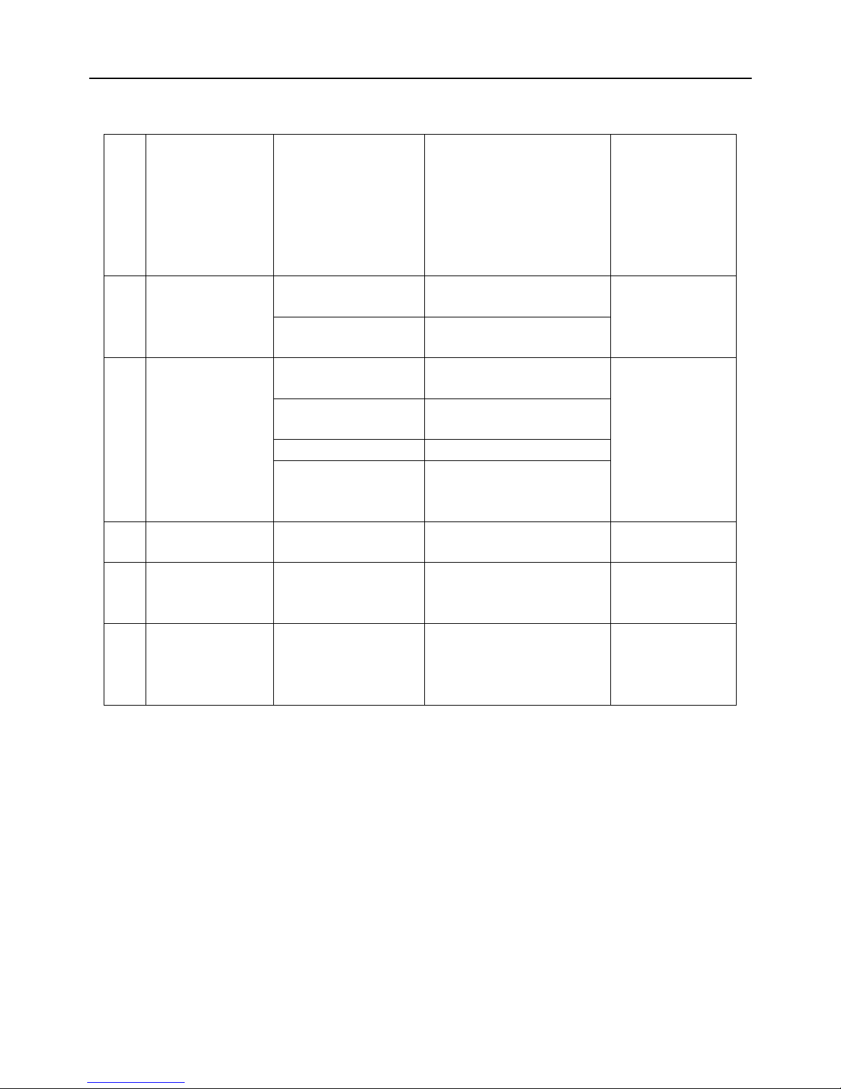
8
Vertical range is not
within 90 ± 2 degree
with large deviation
Fault occurs when the
dome device is in tilt
movement. It may be
caused by obstacle of
camera of other object,
which lead to early tilt
movement
Check and adjust the mechanical
installation
Wrong setting Set the protocol, baud rate and
address of dome device
9
Self-test is normal,
but cannot control
Improper connection of
control cable
Check the circuit
Overload or too long
distance transmission
Add driver
Improper contact of control
cable
Check the circuit
slip ring is demage Replace slip ring
10
Insensitive control of
dome device
RS-485 protective
discharge arresters
broken
Change 485 protective discharge
arresters
Mostly happen in the
connection
11
Call out function fails System failure caused by
noise interference
Restart the dome device
12
Auto action of dome
device periodically
No transmission auto “call
back” function is set to the
dome device
Called this setting
13
One dome working
well while the other
does not under
identical operaion
Something wrong with the
setting or wiring
check the setting and wiring
again
 Loading...