

Page 1

Introduction
NX Series
Network Camera & Video Server
NX173 / NX288 / NX301
NX589 / 599
Installation Guide
Page 2

Introduction
Notice:
Signal Communications Limited reserves the right to make improvements to the
product described in this manual at any time and without notice.
This manual is copyrighted. All rights are reserved. This manual should not be
copied, reproduced or translated in whole or part without prior consent from Signal
Communications Limited.
TeleEye is a trademark of Signal Communications Limited and is registered in China,
European Communities, Hong Kong, US and other countries.
All other trademarks are the property of their respective owners.
Copyright (c) 2009 Signal Communications Limited (A member of TeleEye Group).
All rights reserved.
Version 1.02
Limits of Liability and Disclaimer of Warranty
Signal Communications Limited has taken care in preparation of this manual, but
makes no expressed or implied warranty of any kind and assume no responsibility for
errors or omissions. No liability is assumed for incidental or consequential damages in
connection with or arising out of the use of the information or accessories contained
herein.
Features and specifications are subject to change without prior notice.
Page 3

Introduction
Contents
1. Introduction........................................................................................1
1.1. Hardware Features .................................................................................1
1.2. Functional Features................................................................................2
1.3. Packages Contents .................................................................................3
2. Hardware Installation .......................................................................7
2.1. Cautions .................................................................................................7
2.2. NX173.................................................................................................... 8
2.3. NX288.................................................................................................. 10
2.4. NX589/NX599…...…………………………………………………..13
2.5. NX301.................................................................................................. 17
3. Software Installation........................................................................20
3.1. PC Requirements .................................................................................20
3.2. IP Setup Utility.....................................................................................20
3.3. WX-M4Lite..........................................................................................21
4. Connecting NX173/NX288/NX589/NX599/NX301 .......................21
4.1. Configuration .......................................................................................21
4.2. Web Browsing......................................................................................22
4.2.1. Connecting to Remote Site ..........................................................22
4.2.2. Settings.........................................................................................24
Appendix A: Specifications....................................................................25
Appendix B: Dimension .........................................................................26
Page 4

NX User Guide PAGE 1
Introduction
1. Introduction
TeleEye NX Series is a complete portfolio of professional and practical network
camera and video server utilising our proprietary SMAC-M compression technology.
The NX range offers the balanced combination of high-quality video, mobility,
scalability and cost effectiveness. By using TeleEye NX, users can build an integrated,
scalable, wired or wireless IP & mobile video surveillance solution over existing
network infrastructure. With the support of TeleEye versatile back-end applications,
users can gain extra control over their business management beyond security.
1.1. Hardware Features
NX173 Outdoor Vandal Resistant Network Dome
Outdoor and vandal resistant IP surveillance
f = 3.6mm fixed iris lens
0.5 Lux / F1.2
IP66 weather proof & vandal resistant
Auto gain control
Back light compensation
Supporting mobile phone viewing
NX288 IR Vandal Resistant Network Dome
IP surveillance in complete darkness
Ultra Hi-Resolution 1/3” CCD, HQ1 Technology
f = 2.9-10mm vari-focal auto-iris IR lens
True day & night operation with switchable IR-cut filter
10 IR LEDS, ~15m illumination range
0.13 Lux / F1.3 (IR OFF), 0.0 Lux (IR ON)
IP66, vandal resistant, 3-axis adjustment
Power over Ethernet
Supporting mobile phone viewing
Page 5

NX User Guide PAGE 2
Introduction
NX589/NX599 High Speed Dome
IP-based high speed dome for all round surveillance
Optical zoom: 26X, Digital zoom: 12X
128 presets, 6 patrols, 3 patterns
Day / night minimum illumination: 0.01 Lux
8 privacy zone maskings
IP66 weather proof standard
Supporting mobile viewing
NX301 Video Server
Converting analogue camera into IP-based or mobile surveillance
1 video in, 1 audio in / out, 1 alarm in / out, 1 RS485 out
Refreshing rate up to 25/30fps
USB connection for mobile data modem
Power over Ethernet
Power output for DC 12V camera
sureLINK for dynamic IP Internet connection
Supporting popular third party telemetry protocols
Supporting mobile phone viewing
1.2. Functional Features
Scalable and Flexible Network Configuration
- Flexible connections: LAN, ADSL, mobile network, etc.
- sureLINK, support both static and dynamic IP
- Monitoring and recording up to 16 cameras with TeleEye WX-M16 Multi-
site software
- Live video delivery over bursty and limited network resources with TeleEye
proprietary SMAC-M video compression technology
Advanced Security Design
- Connection with user name and password protect
Mobile and Portable Video Surveillance
- Mobile monitoring with TeleEye M-303 mobile video monitoring software
- 3G USB modem supported (NX301 only)
Professional and Robust Design
- Switchable IR-cut filter (NX288 only)
Cost-effectiveness for All Infrastructures
- Power over Ethernet (PoE) (NX301 and NX288 only)
Page 6
NX User Guide PAGE 3
Introduction
Packages Contents
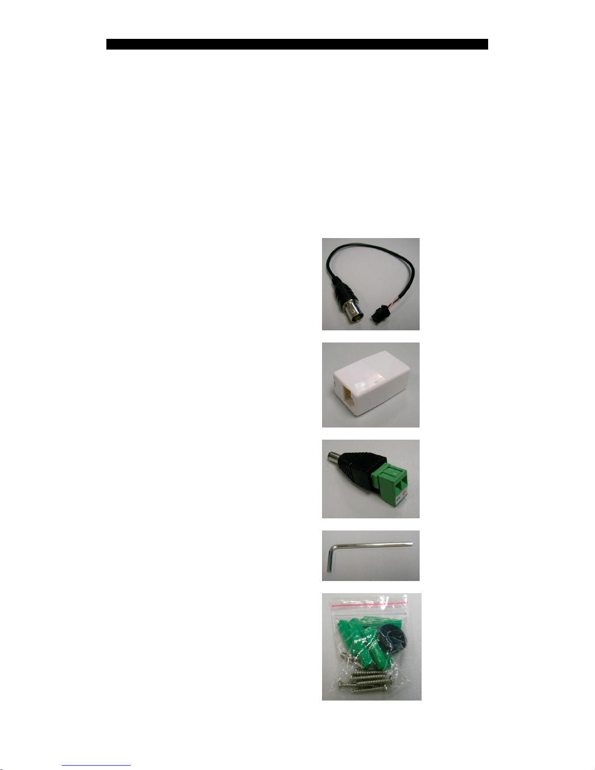
After removing the package, make sure you have the following items:
For NX173
NX173 network camera
Warranty card and registration code
User Guide
Software CD
Analog video cable
RJ-45 Ethernet adapter
Power jack converter
Screws driver
Wall mount screws and plastic wall plugs
Page 7

NX User Guide PAGE 4
Introduction
Label
For NX288
NX288 network camera
Warranty card and registration code
User Guide
Software CD
Analog video cable
RJ-45 Ethernet adapter
Screws driver, wall mount screws and
plastic wall plugs
Page 8

NX User Guide PAGE 5
Introduction
For NX589/NX599
NX589/NX599network camera
Warranty card and registration code
User Guide
Software CD
RJ-45 Ethernet adapter
Network and alarm cable
AC Adapter
AC and Earth cable
wall mount screws, bracket screws and
acrylic dome shield screws
Page 9

NX User Guide PAGE 6
Introduction
For NX301
NX301 video server
Warranty card and registration code
User Guide
Software CD
Wall mount screws and plastic wall plugs
DC Adapter
Power cord
RJ-45 Ethernet cable
Page 10

NX User Guide PAGE 7
Hardware Installation
2. Hardware Installation
2.1. Cautions
Do not install the camera in extreme temperature conditions. Do use the camera
under conditions where temperatures are within 0°C ~ +50°C : (32°F ~ 122°F)
Do not install the camera under unstable lighting conditions. Severe lighting
change or flicker can cause the camera to work improperly.
Do not install or use the camera in an environment where the humidity is high. It
can result in poor-quality image.
Do not disassemble the camera. There are no user serviceable parts inside it.
Opening or removing the camera’s cover may expose you to dangerous voltage
or other hazards. Refer all servicing to qualified personnel only.
Do not touch the imaging surface of sensor. Use a soft cloth with alcohol to clean
the surface if it is touched accidentally.
Ensure the supply voltage is correct before operation!
Do not focus the camera on the sun directly.
Page 11
NX User Guide PAGE 8
Hardware Installation
2.2. NX173
Installation/Configuration
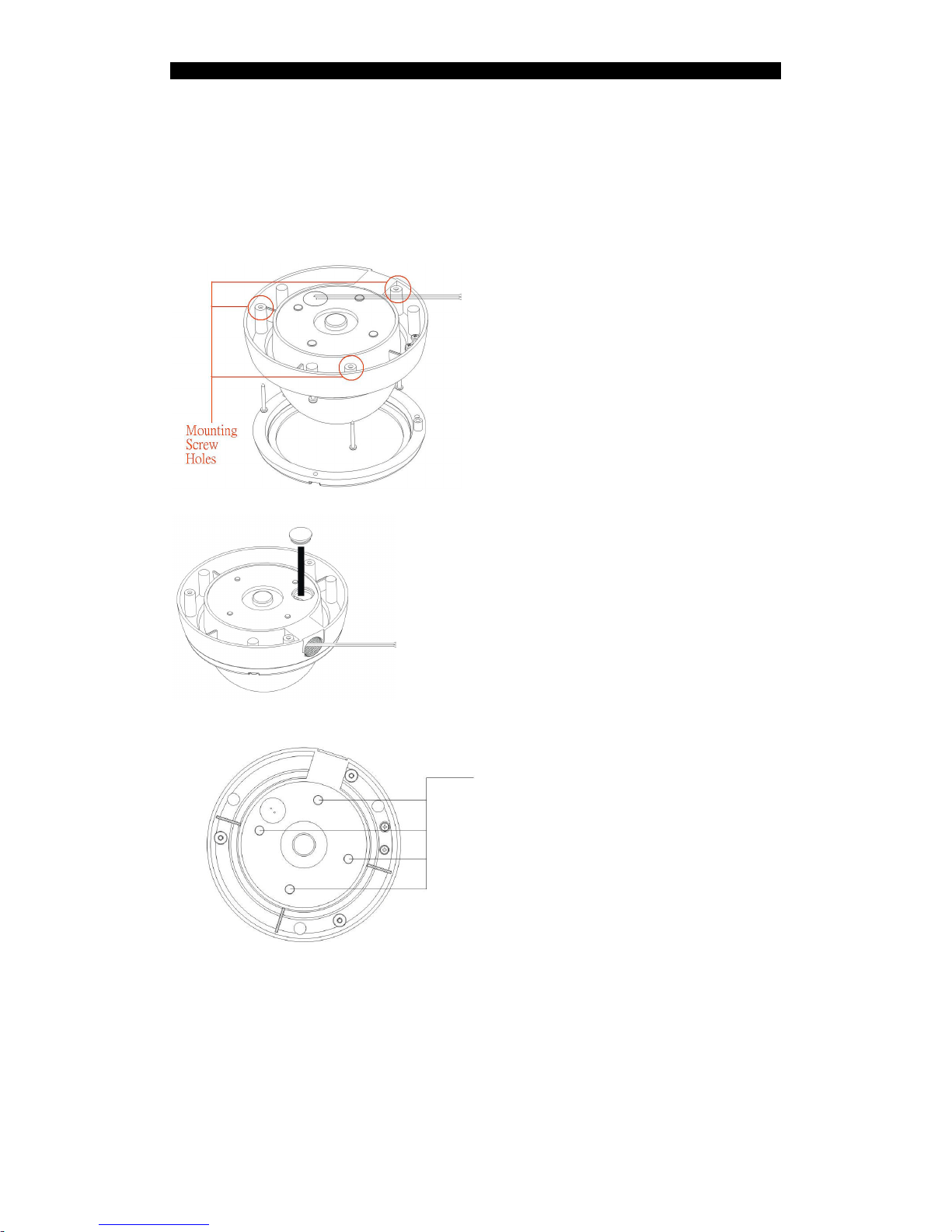
The positions marked with circles show
the holes for mounting screw.
There is an alternate hole for the power
cable, Ethernet cable and alarm cable.
When this hole is used, the upper hole has
to be sealed with the plastic cork.
These 4 plastic corks should never be
removed when water-proof is a critical
requirement.
Page 12
NX User Guide PAGE 9
Hardware Installation
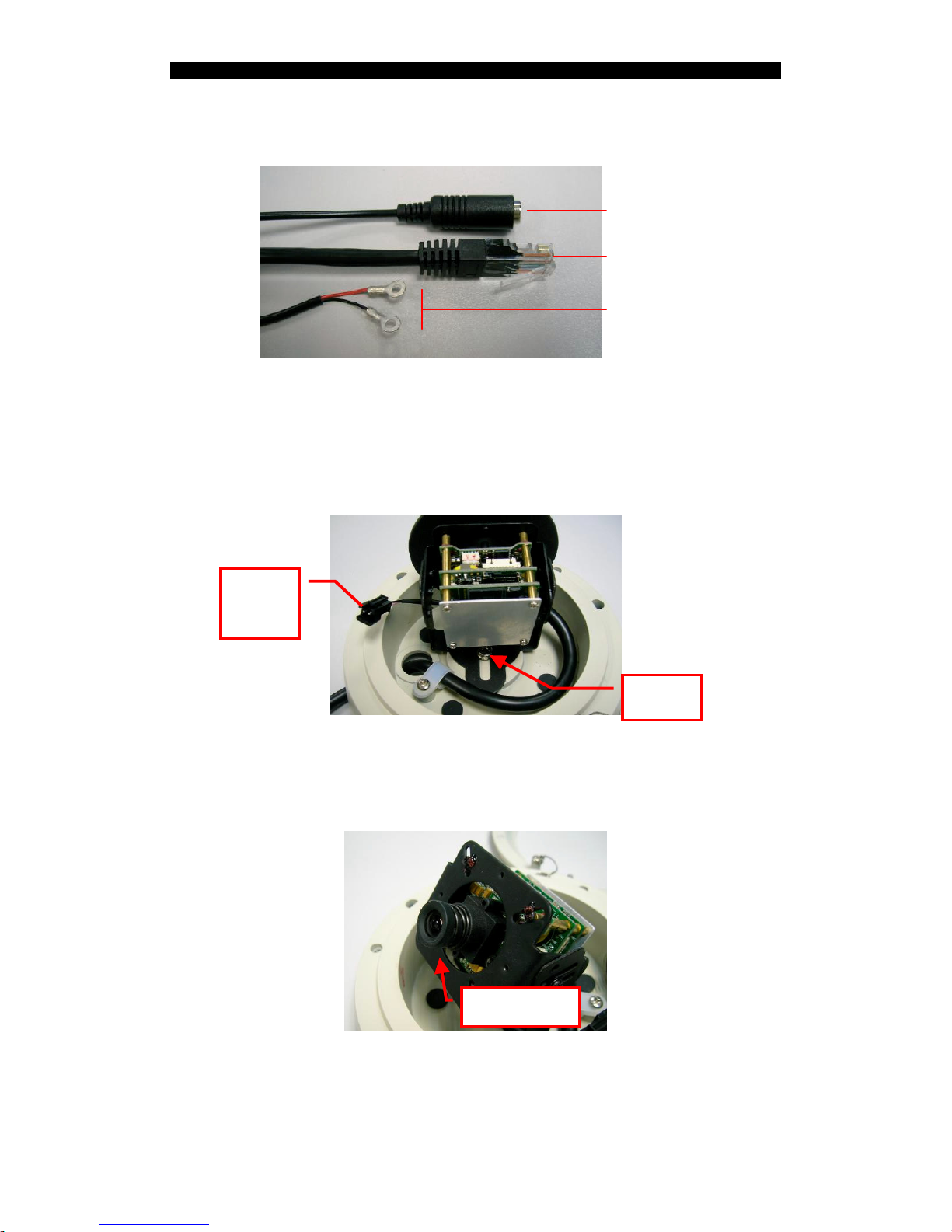
With reference to the following figure, connect the power cable with a 12V DC
supply, Ethernet cable through the LAN adapter and alarm cable to the camera.
After mounting the camera on the wall or ceiling, connect the analog video output to a
monitor by using the analog video cable. Loose the screw to adjust the direction
(pan/tilt) of the camera.
Tighten the screw to fix the direction of the lens. Then, adjust the focus by tuning the
ring of the lens.
Finally, disconnect the analog video cable and close the camera cover.
Video
output
Screw
Adjust focus
Power cable (DC12V IN)
Ethernet cable
Alarm cable
Page 13
NX User Guide PAGE 10
Hardware Installation
2.3. NX288
Installation/Configuration
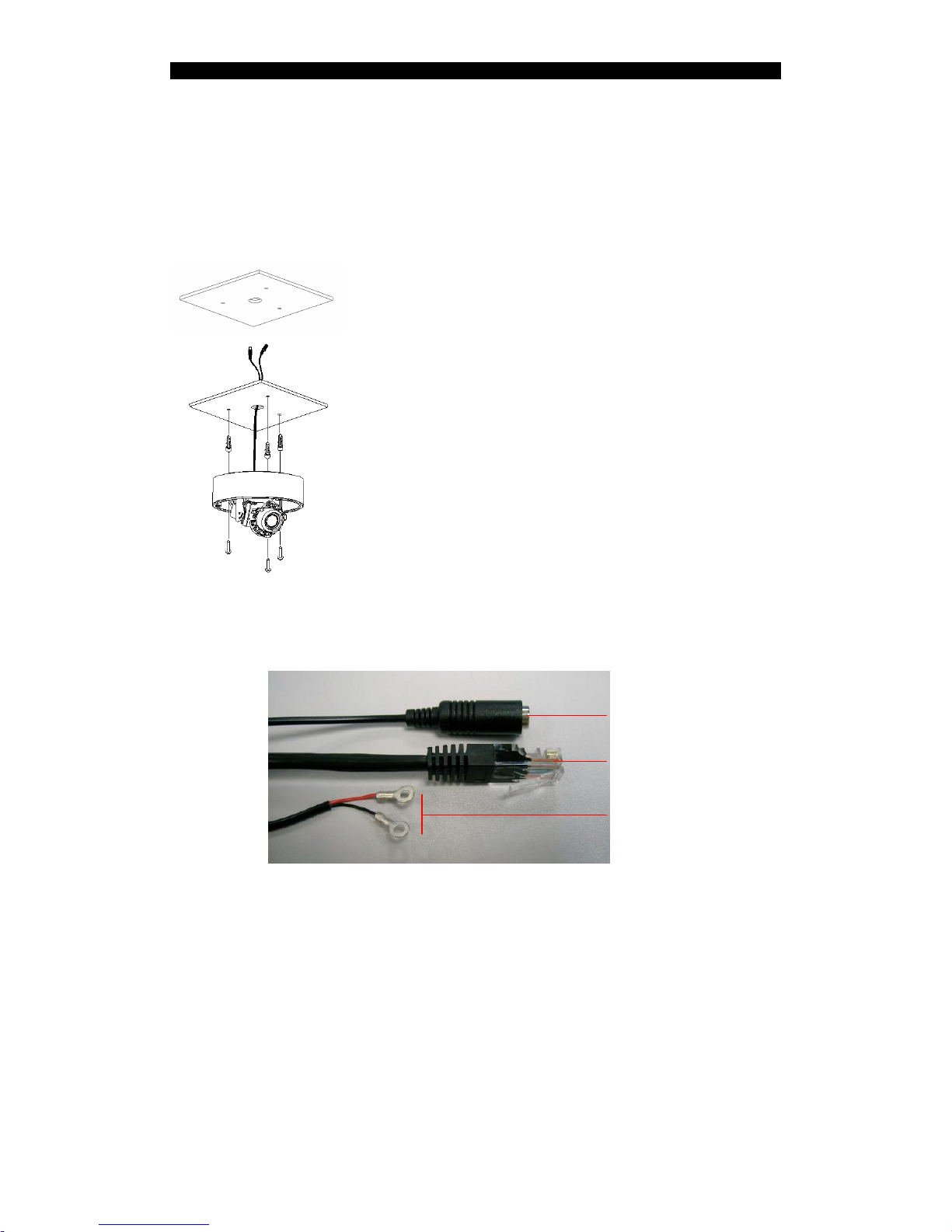
Drill ф25mm hole on the ceiling for video and power
connector cable to pass through.
Take off the dome cover from the camera. Use
specified holes inside the camera base for installation.
Finally, with reference to the following figure, connect the power cable with a 12V
DC supply, Ethernet cable through the LAN adapter and alarm cable to the camera.
Power cable (DC12V IN)
Ethernet cable
Alarm cable
Page 14
NX User Guide PAGE 11
Hardware Installation
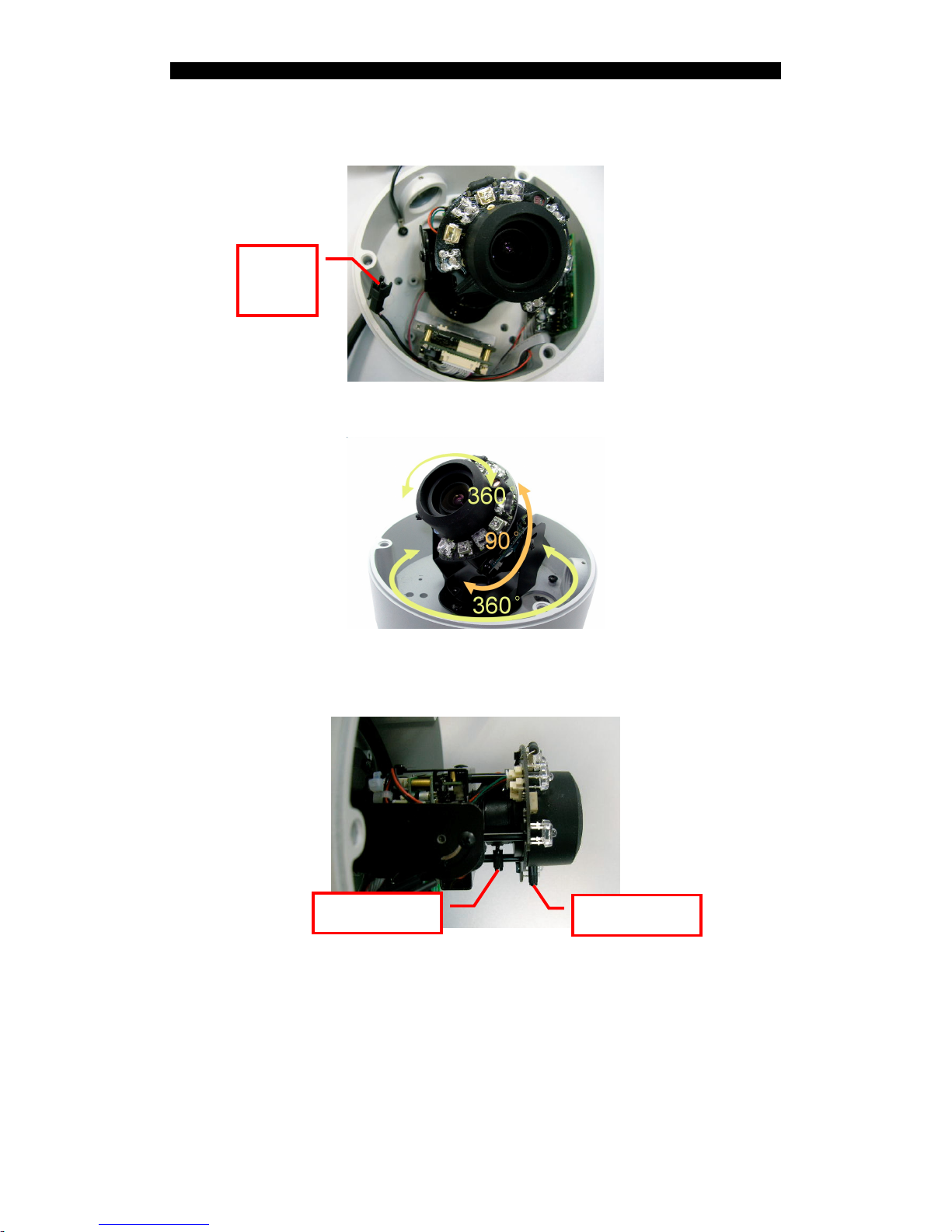
After mounting the camera on the wall or ceil, connect the analog video output to a
monitor by using the analog video cable.
Adjust the direction (pan/tilt/rotation) of the camera.
Adjust the focal and focus by sliding the sticks at the side of the lens.
Adjust focus
Adjust focal
Video
output
Page 15
NX User Guide PAGE 12
Hardware Installation
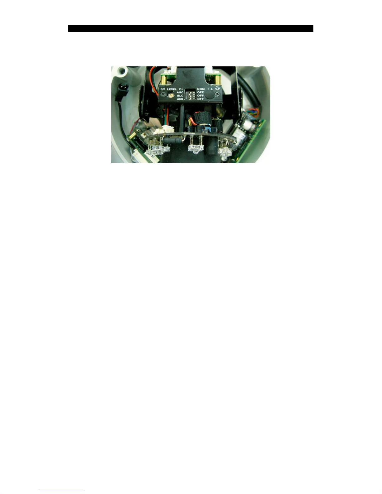
Adjust the IRIS level of Auto Iris lens by tuning the “DC LEVEL” as shown in the
following figure.
Adjust the switches with reference to the following description.
FL: Flickerless
FL: In FL mode, the shutter speed is 1/100sec. (NTSC system) / 1/120sec.
(PAL).
If choose FL mode, [AES] switch should be off.
NOM: Normal position
AGC: Automatic Gain Control
ON: AGC level of gain varies from 0 to 26dB.
OFF:AGC OFF. The level of gain is fixed at 0dB.
BLC: Backlight Compensation
When the object is dark by strong light, please turn on BLC to make object
become bright.
AES: Automatic Electronic Shutter
ON: The range of shutter speed from 1/60 (1/50sec.) to 1/100,000 sec.. This
mode is employed for using a manual iris lens.
OFF: The shutter speed is 1/60sec. (1/50sec.).
When an auto iris lens is applied, AES should be off.
Finally, disconnect the analog video cable and close the camera cover.
Page 16
NX User Guide PAGE 13
Hardware Installation
2.4. NX589/NX599
Installation/Configuration
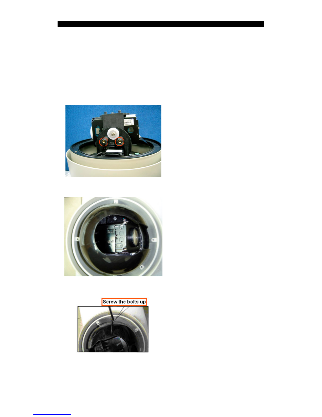
-Installation steps of shield dome.
1. The positions marked with circles
show the fixing holes of acrylic
shield, i.e. four M3 screw holes.
2. Aim the open end of shield dome at
the lens of camera. Aim the 4 holes
on the shield to the 4 M3 screw
holes on the dome device.
3. Screw the four M3 bolt up
Page 17
NX User Guide PAGE 14
Hardware Installation
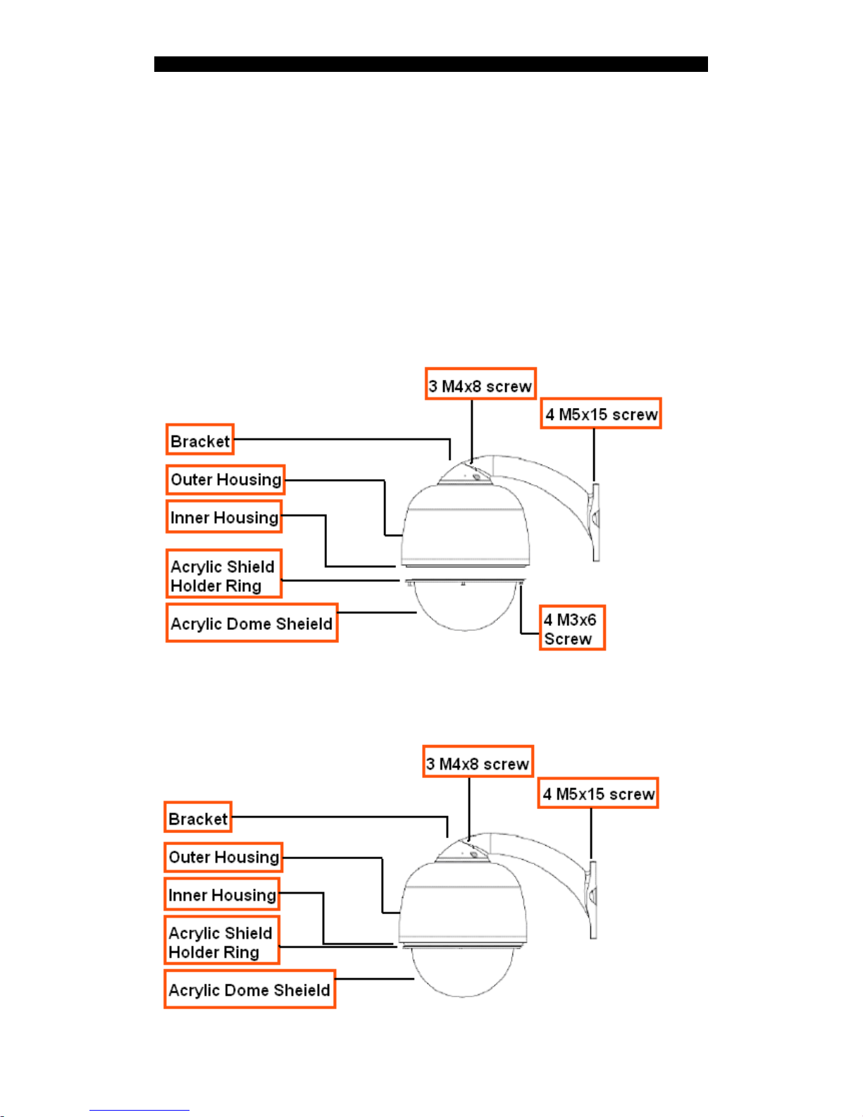
-Installation Instruction of the Acrylic Dome Shield
Installation of the Acrylic Dome Shield
1. Remove Acrylic DOME shield (Please do not scrape the Acrylic shield. It is
recommended to wear
cotton gloves when operate).
2. As shown in the figure below, first take the flexible flat cable through connector
above the base
plate and buckle it on the connector. Then buckle the cable on the connection below
the CAMERA.
3. Lock the CAMERA up and fix the screws.
4. Install Acrylic shield
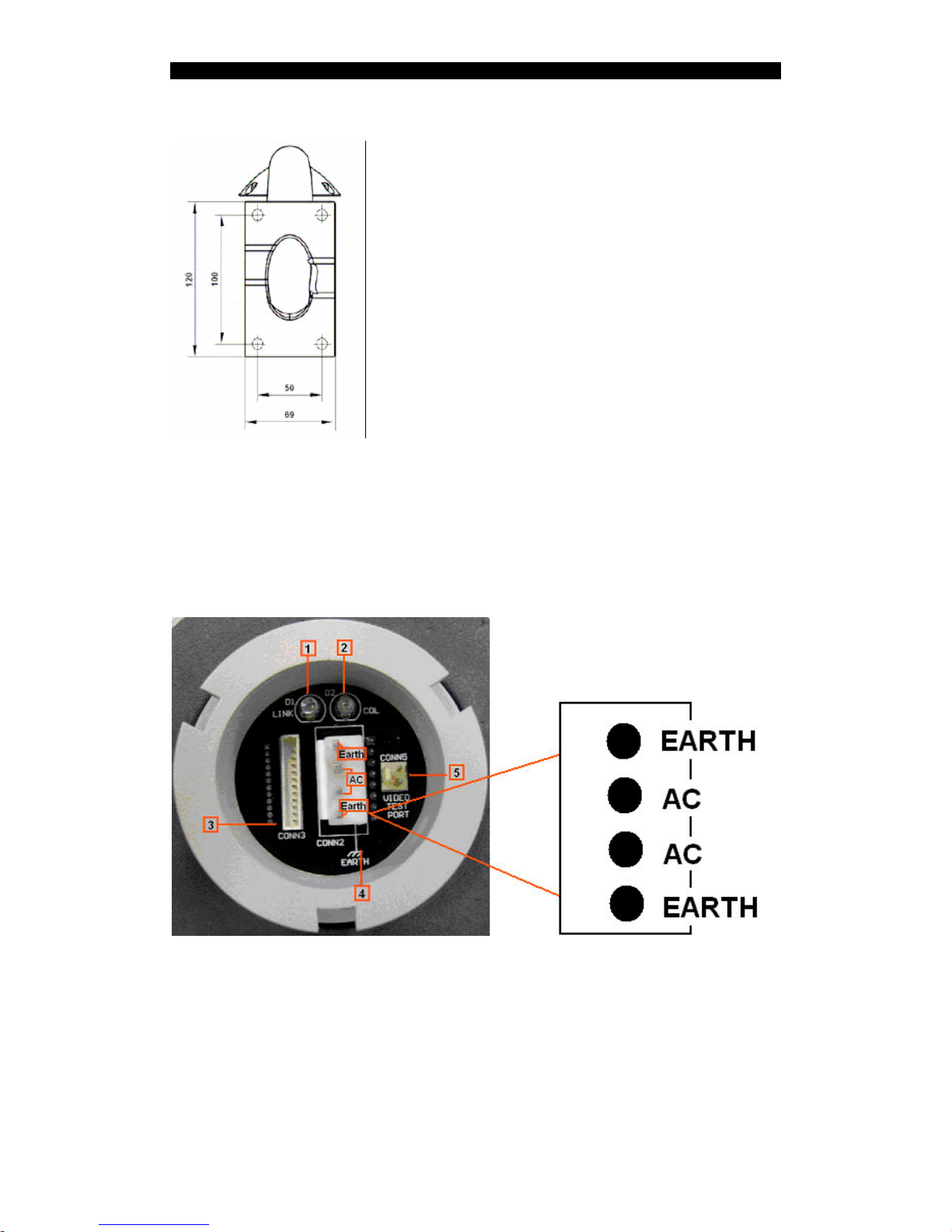
-Install Bend-Tube-Style Bracket
1. Connecting the dome to the wall mount with the bracket.
Page 18
NX User Guide PAGE 15
Hardware Installation
2. Wall mount bracket installation
-Wiring of Dome System
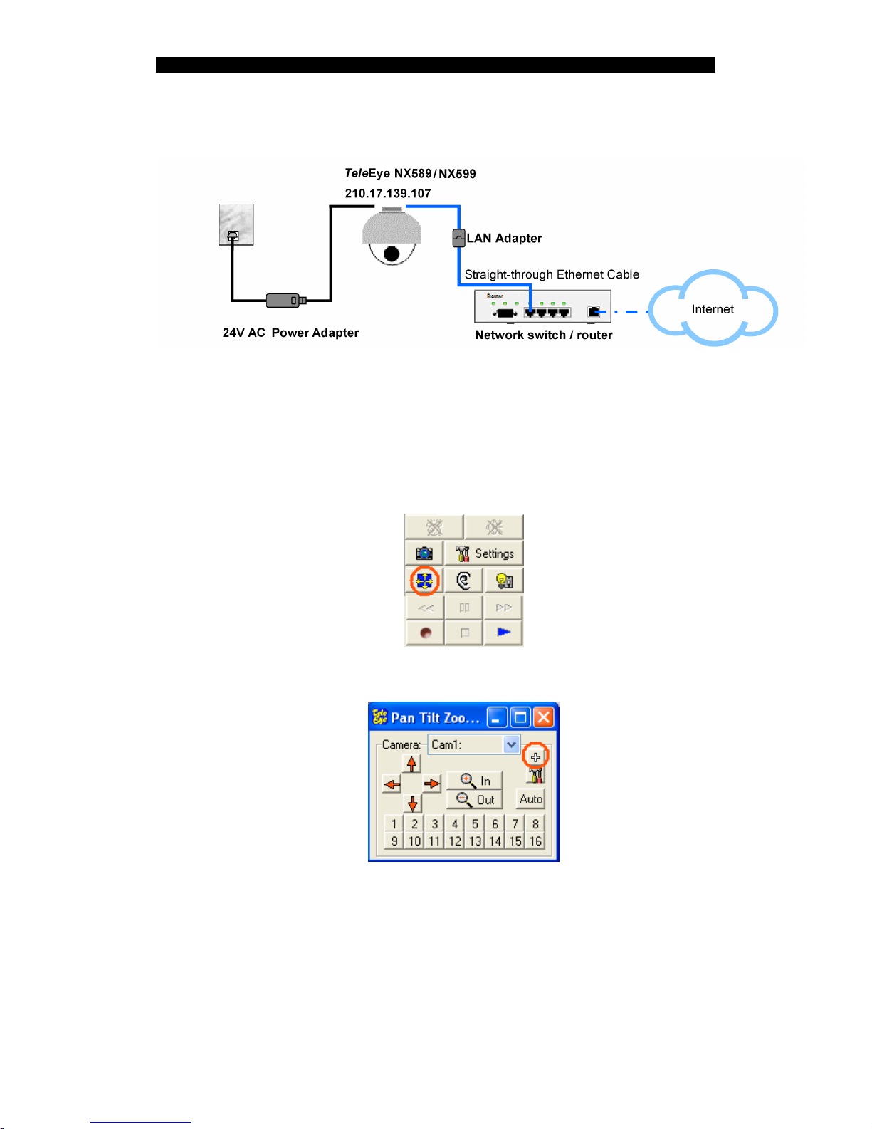
Finally, with reference to the following figure, connect the AC Adapter and AC and
Earth cable, network cable through the LAN adapter and alarm cable to the camera.
During installation, you can use the analog video cable to connect to a video monitor
for testing.
1: LINK LED.
2: COL LED.
3: Network and alarm connector.
4: AC power and Earth connector.
5: NC
Bottom of the NX589/NX599
Page 19
NX User Guide PAGE 16
Hardware Installation
-Network Configuration
-NX589/NX599 OSD Control
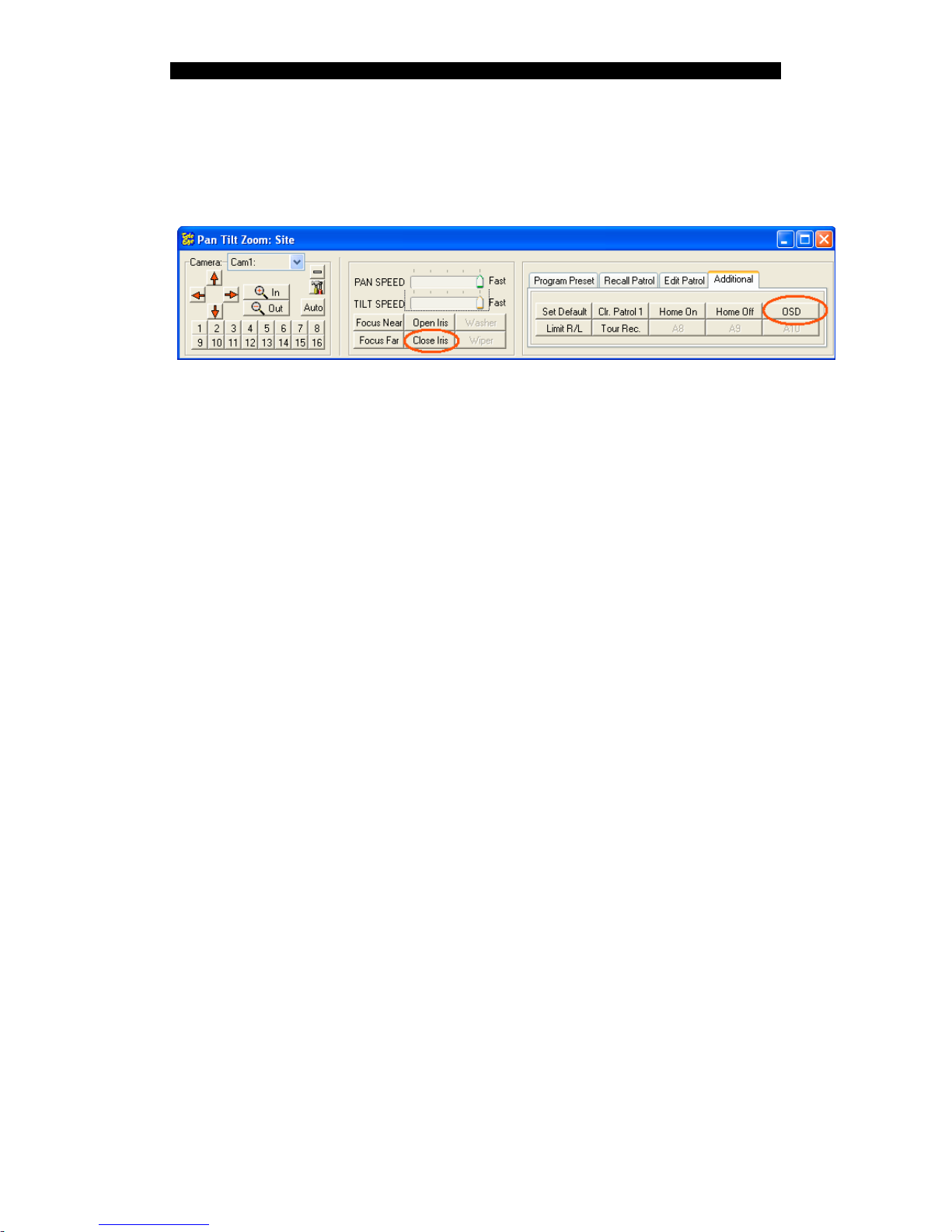
Use of the main menu:
In WX-M4lite, pop up a PTZ screen by clicking the PTZ icon
on the left corner of the control panel.
And click the maximize screen icon
Page 20
NX User Guide PAGE 17
Hardware Installation
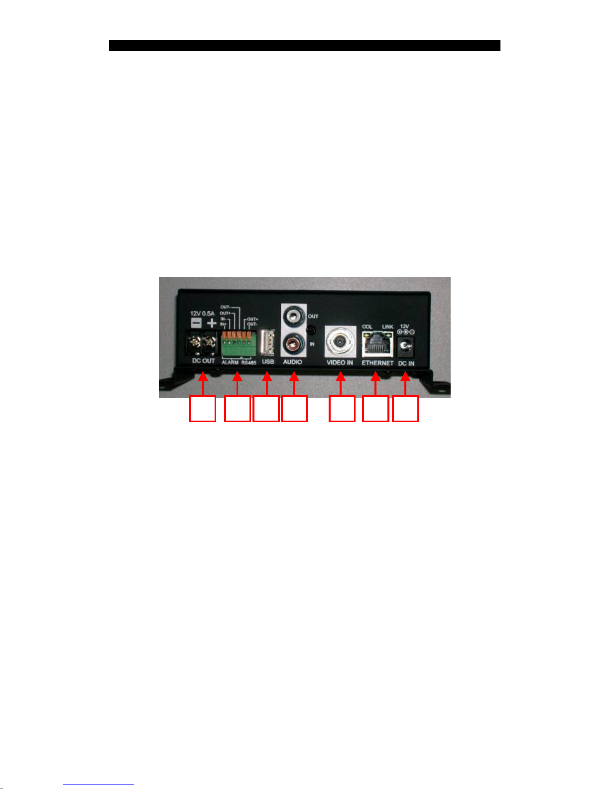
Then, click the [Additional] tab page. After click the OSD icon, an OSD menu on the video
can be seen. The up and down arrows can be use as option selection. The left and right arrows
can be use as enter the submenu or change the value or setting of an option. Press the Close
Iris icon when quit the sub menu or main menu.
-Privacy Zone Mask Setting
Set in OSD main menu -> Camera options -> Mask setting
1.Number ( 1 ~~ 8 ) << Mask sector number selection, press left / right arrow to
select.
2.Mask Edit << Mask editing, press left / right arrow or [Open Iris] to enter, then
use pan / tilt / zoom to select region of video to be covered by a
black mask, press [Close Iris] to exit to previous menu.
3.Mask Display ON/OFF << Mask Display ON/OFF, press left / right arrow to
select.
Page 21
NX User Guide PAGE 18
Hardware Installation
2.5. NX301
Front Panel
There is a red LED on the front panel. It flashes when just powered on and indicates
the NX is starting. It lights continuously when the starting process is completed.
Rear Panel
The following figure shows the rear panel of NX301.
1. DC in: Connect power supply (12V DC). If Ethernet jack is connected to a
switch/router with PoE supported, the DC-IN is not necessary.
2. Ethernet Jack (10/100 Base-T):
- This socket is used for connecting NX to the network (e.g. LAN)
- This socket includes {COL LED} and {LINK LED}
- {COL LED}: When ON, indicates that collision is occurring on the network
- {LINK LED}: When ON, indicates that NX is connecting to the network and
ready to function
3. Standard BNC connector for video source input
4. Audio in: Connect audio input device with RCA jack for audio monitoring and
recording
Audio out: Connect audio output device (e.g. speaker) with RCA jack for public
addressing
5. USB: For connecting to 3G USB modem
6. Alarm in: Alarm input
Alarm out: Relay (switch) output
5 4 3 2 167
Page 22
NX User Guide PAGE 19
Hardware Installation
RS485 out: 2-way terminal block for connecting a PTZ camera
7. DC output: Supply 12V, 0.5A DC to camera.
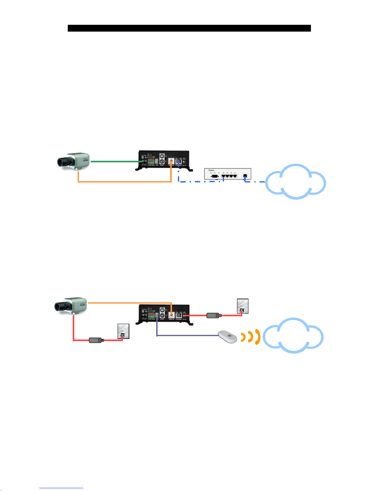
Installation / Configuration
Two configurations are available:
Configuration 1: Through Ethernet network
TeleEye NX301
210.17.139.146
TeleEye SF373
Internet
Network Switch
/ Router
with
PoE supported
Straight-through
Ethernet cable
Video cable
Power cable
Step 1: Connect a camera to NX301 with video cable
Step 2: Connect NX301 to a router/switch with a Ethernet cable
Step 3: If the router/switch does not support “Power over Ethernet (PoE)”, connect
NX301 with a power adapter
Step 4: When power is applied, the front panel LED is flashing. Wait for around 1
minute for the LED to light continuously.
Configuration 2: Through 3G network
Power Adapter
T
ele
Eye NX301
210.17.139.146
TeleEye SF373
Internet
Video cable
Camera’s
DC Adapter
USB 3G Data Modem
USB cable
Step 1: Connect a camera to NX301
Step 2: Connect NX301 to a USB mobile data modem
Step 3: Connect NX301 with a power adapter
Step 4: When power is applied, the front panel LED is flashing. Wait for around 1
minute for the LED to light continuously.
Page 23
NX User Guide PAGE 20
Software Installation
3. Software Installation
3.1. PC Requirements
Computer Personal Computer
Processor Intel Pentium IV 2.4GHz or above
Memory 1GB RAM or above
Hard Disk Minimum 1GB hard disk space required
Drive CD-ROM
Display 1024x768, true colour, with Direct3D supported
Sound Sound card is required
Ethernet Card 10/100Mbps or above
Port Serial Port
Operating System Microsoft Windows 2000 / XP / Vista
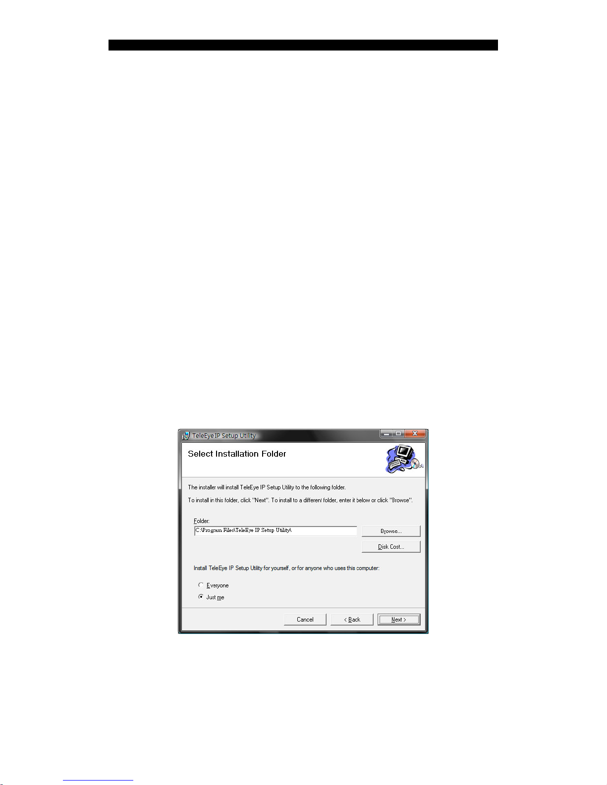
3.2. IP Setup Utility
Click [Next] in the welcome screen and following instructions in the installer.
Select the installation folder in the following window. Then click [Next].
Click [Next] to confirm the installation and wait the installation complete.
Page 24

NX User Guide PAGE 21
Software Installation
3.3. WX-M4Lite
Click [Next] in the welcome screen and follow the instructions in the installation
wizard. Select [Typical] in the following screen and click [Next].
Click [Next] to confirm the installation and wait the installation complete.
When the installation is successful, it is recommended to restart the PC before
using the software. Click [Finish] to complete the installation process.
Page 25
NX User Guide PAGE 22
Connecting NX173/NX288/NX589/NX599/NX301
4. Connecting
NX173/NX288/NX589/NX599/NX301
4.1. Configuration
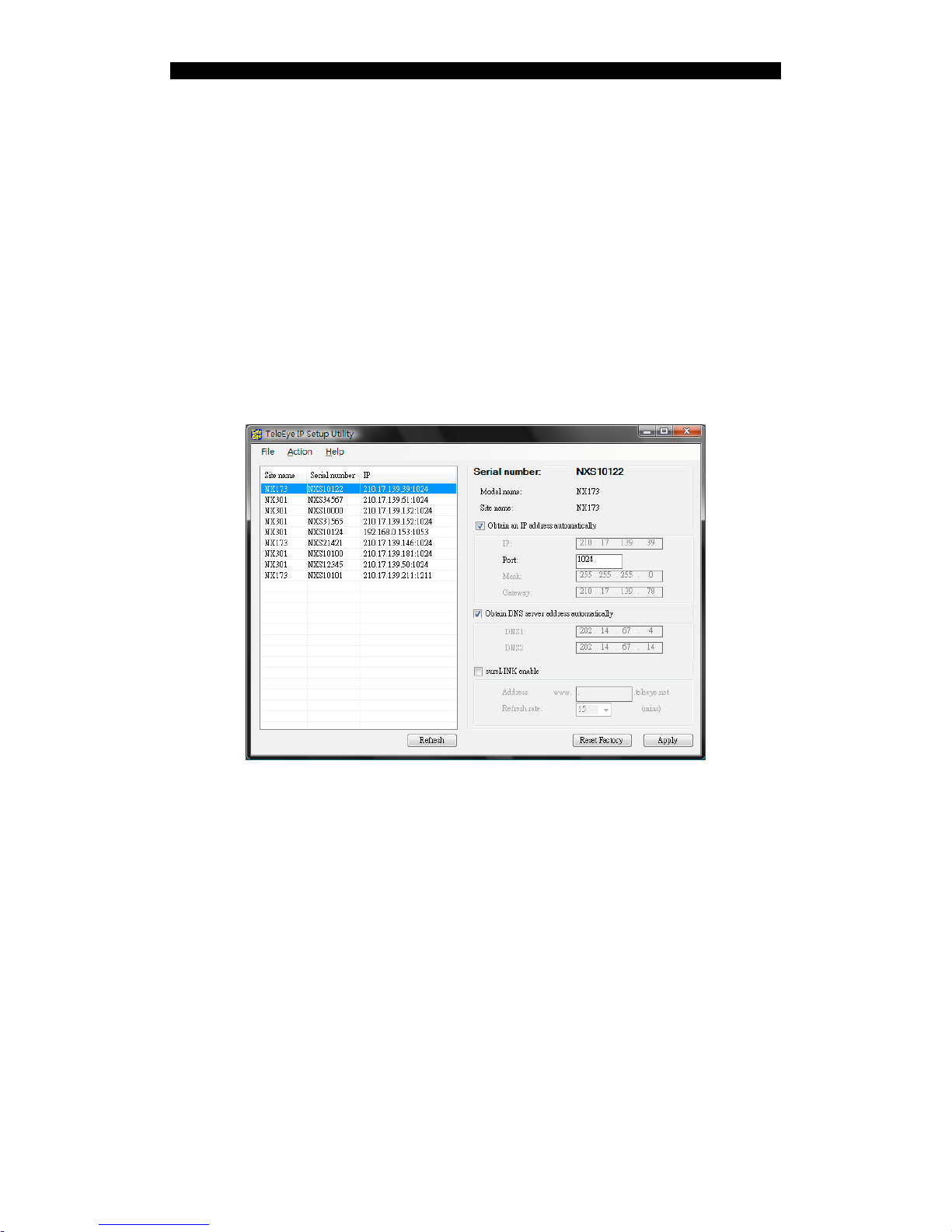
Step 1: Double click the [TeleEye IP Setup Utility] icon on the Windows desktop to
run the utility.
Step 2: The list on the left shows the NX network cameras inside the network of the
PC. By comparing the [Serial number] column with the serial number of the
camera to be configured, click on that row. The basic information such as IP
address and model number is shown on the right.
Note: If the camera is not found, try to press the [Refresh] button and wait for a
while.
Step 3: To use another port number instead of the default port, enter the desired port
number in the [Port] field.
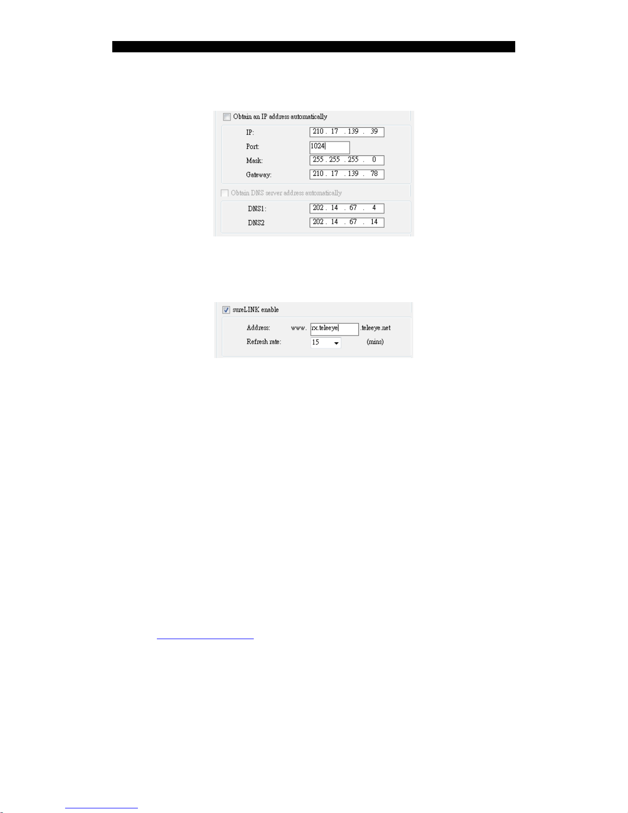
Step 4: To specify another IP address, mask or gateway, un-tick the [Obtain an IP
Page 26
NX User Guide PAGE 23
Connecting NX173/NX288/NX589/NX599/NX301
address automatically]. Then, enter the corresponding information in the
fields.
Step 5: To enable the sureLINK service, tick the [sureLINK enable]. Then, enter the
address and select the refresh rate as the following figure.
Step 6: Click [Apply] to apply the settings.
4.2. Web Browsing
4.2.1. Connecting to Remote Site
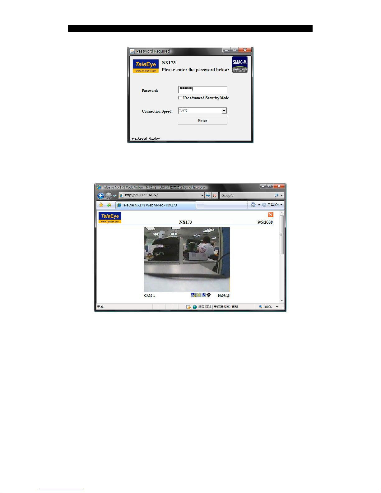
Step 1: Run a web browser such as Internet Explorer. Enter the IP address or
sureLINK address in the address bar. The following window pops up.
Alternatively, double click the corresponding entry on the list in IP Setup
Utility which will open the Internet Explorer and go to that address directly.
Note: Java Runtime Environment is required for the web browser. Please go to
http://www.java.com, follow the instruction to download and install it if it
has not been installed.
Page 27
NX User Guide PAGE 24
Connecting NX173/NX288/NX589/NX599/NX301
Step 2: Enter the password and select the connection speed, then press [Enter]. If the
password is correct, the video should be shown as the following figure.
Page 28

NX User Guide PAGE 25
Connecting NX173/NX288/NX589/NX599/NX301
4.2.2. Settings
There are four buttons under the video screen. The buttons and the corresponding
functions are shown as follows:
:
Change to smaller resolution
:
Change to larger resolution
:
Select the video quality
:
Toggle the switch
:
Event status - no event
:
Event status - Event triggering, press to clear the event
:
Event status - Event triggered, press to clear the event
Page 29
NX User Guide PAGE 26
Appendix A: Specifications
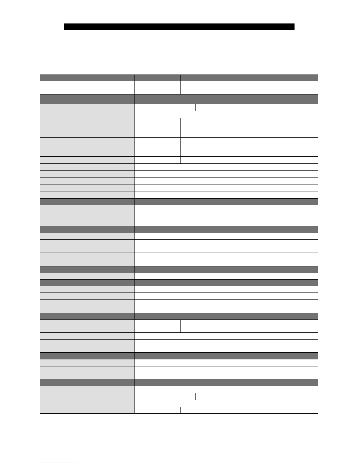
Appendix A: Specifications
MODEL NX301 NX288 NX173 NX589/NX599
Single Channel
Video Server
IR Vandal Resistant
Network Dome
Vandal Resistant
Network Dome
Network Speed
Dome
VIDEO AND AUDIO
IMAGE SENSOR
−
1/3″ colour CCD 1/4″ colour CCD
RESOLUTION
(P): 720 × 576, 360 × 288; (N) 720 × 480, 360 × 240
MINIMUM ILLUMINATION
−
0.0 Lux (IR On) 0.5 Lux (F=1.2)
Day: 0.07 Lux
Night: 0.01 Lux
(F=1.6)
LENS
−
f = 2.9 - 10mm
Vari-focal auto-iris
lens
f = 3.6mm
Fixed iris lens
F=3.5 – 91mm
Optical:26x /
Digital: 12x
IR RANGE
−
15m
− −
VIDEO INPUT PAL / NTSC (auto)
−
AUDIO INPUT 1 channel, RCA, line level
−
AUDIO OUTPUT 1 channel, RCA, line level
−
AUDIO BIT RATE 7.2 / 32kbps
−
VIDEO REFRESHING FRAME RATE 25/30fps
TELEMETRY
RS485 OUTPUT Yes
−
PRIVACY ZONE MASKING
−
On / Off, 8 masks
AUTO RUN
−
128 Presets, 6 Patrols, 3 Patterns
CONNECTIVITY
NETWORK INTERFACE Ethernet (RJ-45 Wired, 10/100 Base-T)
NETWORK PROTOCOL TCP/IP, DHCP, HTTP, SNTP, DDNS, DNS, SMTP
CONCURRENT USERS 6
WEB SERVER Built-in
USB INTERFACE USB 2.0, 480Mbps
−
VIDEO COMPRESSION
COMPRESSION SMAC-M Multi-stream
EVENT HANDLING
EVENT External alarm, motion detection, video loss
ACTION Dial back, email, relay switch Dial back, email
ALARM INPUT 1
RELAY OUTPUT 1
−
POWER
POWER RATING
DC 12V, 12W
(max)
DC 12V, 12W
(max)
DC 12V, 7.4W
(max)
AC 24V, 47W
(max)
POWER OVER ETHERNET Yes
−
POWER OUT
Yes (12V DC,
500 mA)
−
OPERATING ENVIRONMENT
AMBIENT TEMPERATURE
0°C - 50°C -22°C - 60°C
RELATIVE HUMIDITY
< 85%
(no condensation)
−
MECHANICAL DESIGN
WEATHER PROOF
−
IP66
VANDAL RESISTANT
−
Yes
optional
DIMENSION
164mm × 88mm × 50mm
Please refer appendix B
NET WEIGHT 0.44kg 1.02kg 0.63kg 3.6kg
Page 30
NX User Guide PAGE 27
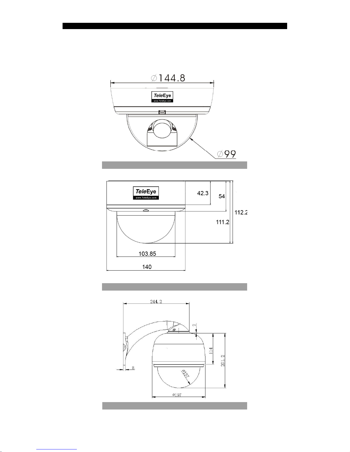
Appendix B: Camera Dimension
Appendix B: Camera Dimension
NX173
NX288
NX589/NX599
 Loading...