

Teledyne TapTone T4000 APX Installation Manual

TapTone T4000 APX
Installation
Manual
M-412-073
Rev. B

This page left blank.
TapTone T4000 APX
Installation Manual
M-412-073
Rev. B
(English)
North Falmouth, Massachusetts
TELEDYNE TAPTONE
49 Edgerton Drive
02556-2828 USA
Phone: 508-563-1000
Fax: 508-564-9945
www.taptone.com

This page left blank

M-412-073 Table of Contents
Table of Contents
1.0 Introduction ................................................................................... 1
1.1 T4000 ACX Acoustic / Cocked Crown / X-Ray Inspection System .. 1
1.2 T4000 PX Proximity / X-ray Inspection System ................................ 2
1.3 T4000 SSV-X Fill_xr Level Inspection System ................................. 3
2.0 Safety Precautions ........................................................................ 4
2.1 General Safety Precautions ............................................................. 4
2.2 Specific Cautions and Warnings ................................ ...................... 5
2.3 Safety Label Descriptions ................................................................ 5
2.4 System Lockout / Tag-out Procedure ............................................... 7
3.0 Installation Instructions ................................................................ 8
3.1 T4000 Sensor Configurations .......................................................... 8
3.1.1 Acoustic Configuration (T4000 A) .............................................. 8
3.1.2 Acoustic/Cocked Crown Configuration (T4000 AC) ................... 9
3.1.3 Proximity Configuration (T4000 P) ........................................... 10
3.1.4 Dual Proximity Configuration (T4000 DP) ................................ 11
3.1.5 X-ray Configuration (T4000 X) ................................................. 12
3.1.6 Acoustic/X-ray Configuration (T4000 AX) ................................ 13
3.1.7 Proximity/X-ray Configuration (T4000 PX) ............................... 14
3.1.8 Acoustic/Cocked Crown/X-ray Configuration (T4000 ACX) ..... 15
3.1.9 Acoustic/Proximity/X-ray Configuration (T4000 APX) .............. 16
3.2 T4000 AC, P Stand Installation ...................................................... 17
3.2.1 RTV Crank Stand Installation .................................................. 17
3.2.2 Conveyor Mount Frame Installation (CMS) .............................. 19
3.3 T4000 X-ray Installation ................................................................. 21
3.3.1 Key Points to X-ray Sensor Installation.................................... 21
3.3.2 Stand Tube Cutting Procedure ................................................ 21
3.3.3 Stand Assembly Procedure ..................................................... 22
3.3.4 X-Ray Sensor Installation Procedure ....................................... 23
3.3.5 X-ray Detector Mask Installation .............................................. 24
3.4 Rejector Assembly Installation ....................................................... 25
3.4.1 Ram Installation....................................................................... 26
3.4.2 Air Regulator Installation ......................................................... 27
3.4.3 Connecting the Air ................................................................... 28
3.4.4 Rejector Electrical Connection................................................. 29
3.5 Shaft Encoder Installation ............................................................. 30
3.5.1 Shaft Encoder Mechanical Specifications ................................ 30
TELEDYNE TAPTONE i

M-412-073 Table of Contents
3.5.2 Shaft Encoder Electrical Specifications ................................... 30
3.5.3 Shaft Encoder Installation Instructions..................................... 31
3.5.4 Electrical Connections ............................................................. 32
3.6 Electrical Power Connections ........................................................ 33
3.6.1 AC Power Connections ........................................................... 33
3.6.2 Sensor Cable Connections ...................................................... 35
3.7 Initial Mechanical Setup ................................................................ 37
3.7.1 Acoustic Sensor Setup ............................................................ 37
3.7.2 Cocked Crown Sensor Setup .................................................. 37
3.7.3 Proximity Sensor Setup ........................................................... 37
3.7.4 X-ray Setup ............................................................................. 38
3.7.5 Reject Acknowledge Sensor Setup ......................................... 39
3.7.6 Trigger Sensor Setup .............................................................. 39
3.7.7 Trigger Timing Setup ............................................................... 40
Appendix A – Warranty .......................................................................... 42
Appendix B – Technical Specifications ................................................ 43
B.1 Electronic Control Box Specifications ............................................ 43
B.2 Fill_xr Sensor Specifications .......................................................... 44
Appendix C – X-Ray Safety Survey Plot – B-412-119 ........................... 45
Reference Manuals
M-412-102 TapTone T4000 Operations Manual (English)
M-412-073 TapTone T4000 ACX Installation Manual (English)
M-412-074 TapTone T4000 ACX Operations & Maintenance Manual (English)
M-412-066 TapTone T4000 User’s Manual (English)
Preface
All information within this manual is a copyright of Teledyne TapTone and may not be
duplicated without the written consent or approval from Teledyne TapTone.
Teledyne TapTone reserves the right to make changes to the manual without obligation to
notify any person(s) or entities of revisions. It is recommended that the installation of your
Teledyne TapTone equipment is performed or supervised by an authorized Teledyne
TapTone representative.
TELEDYNE TAPTONE ii

M-412-073 List of Figures
Table of Figures
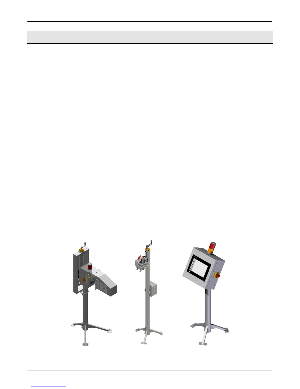
Figure 1-1 T4000 ACX System .............................................................................................................................. 1
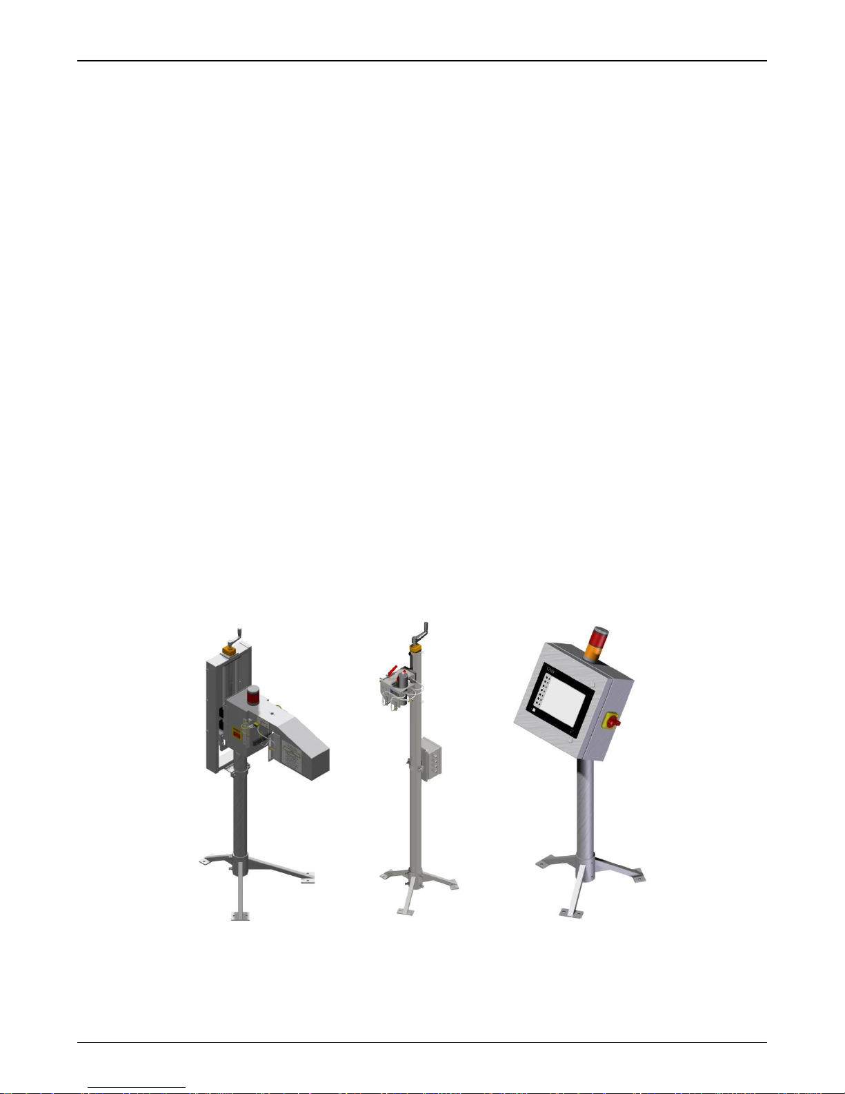
Figure 1-2 T4000 PX System ................................................................................................................................. 2
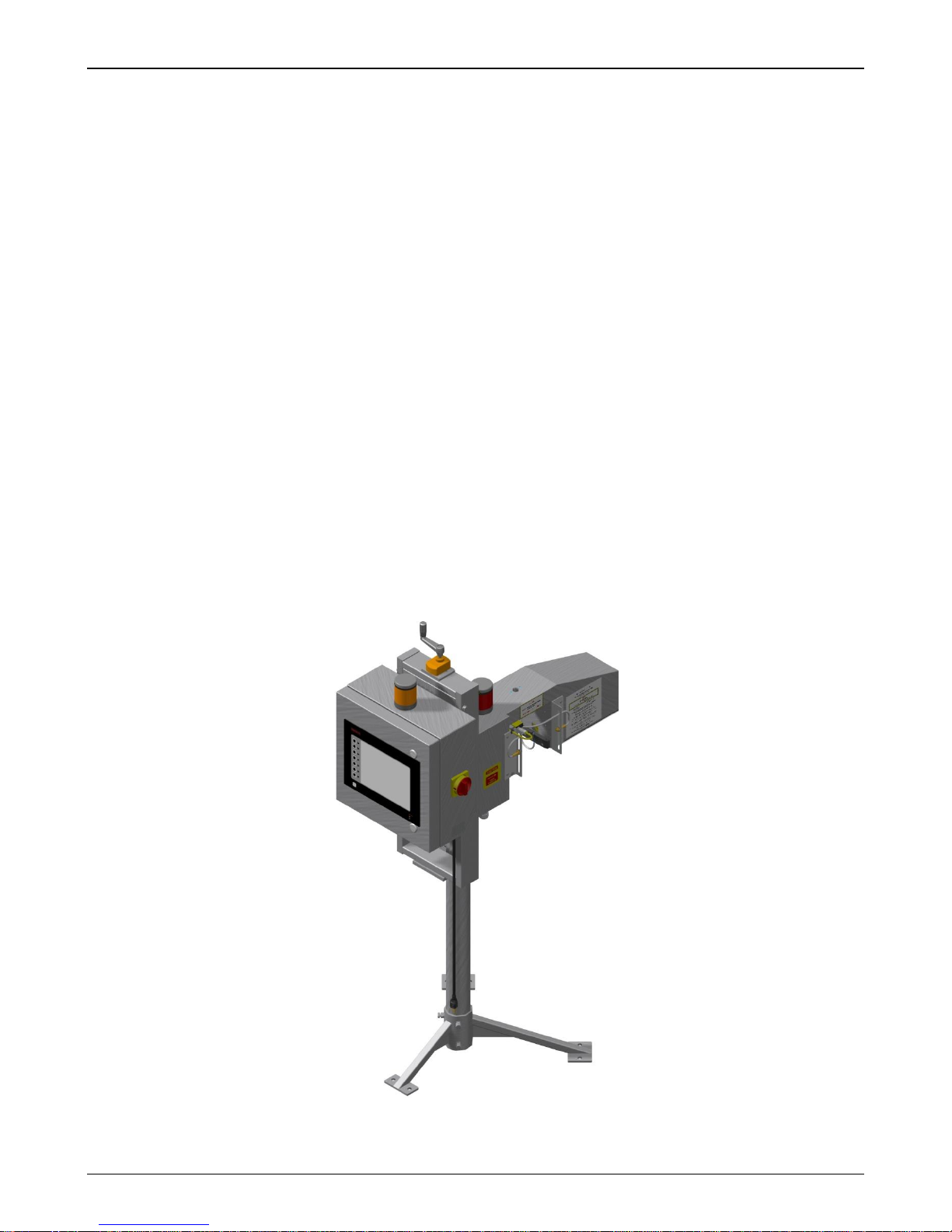
Figure 1-3 T4000 SSV-X System ........................................................................................................................... 3
Figure 2-1 Safety Labels ........................................................................................................................................ 5
Figure 2-2 X-ray Safety Labels .............................................................................................................................. 6
Figure 3-1 Transducer Stand Assembly (RTV) .................................................................................................... 17
Figure 3-2 Conveyor Mount Stand Dimensions (CMS) ........................................................................................ 19
Figure 3-3 Conveyor Mounted Transducer Assembly ......................................................................................... 20
Figure 3-4 Stand Tube Cutting Diagram .............................................................................................................. 21
Figure 3-5 X-ray Mechanical Assembly Diagram ................................................................................................. 22
Figure 3-6 X-ray Mechanical Installation Diagram ............................................................................................... 23
Figure 3-7 X-ray Detector Mask ........................................................................................................................... 24
Figure 3-8 Rejector Specifications ....................................................................................................................... 25
Figure 3-9 Rejector Assembly Adjustment Points ................................................................................................ 26
Figure 3-10 Rejector Regulator / Lubricator Mounting ......................................................................................... 27
Figure 3-11 Rejector Regulator / Lubricator Air Connections .............................................................................. 28
Figure 3-12 Rejector Power Connection .............................................................................................................. 29
Figure 3-13 Shaft Encoder Specifications ............................................................................................................ 30
Figure 3-14 Shaft Encoder Warnings ................................................................................................................... 30
Figure 3-15 Shaft Encoder Mounting Drawing ..................................................................................................... 31
Figure 3-16 Shaft Encoder Wiring ........................................................................................................................ 32
Figure 3-17 AC Power Selector Switch ................................................................................................................ 33
Figure 3-18 AC Power Wiring Diagram ................................................................................................................ 34
Figure 3-19 Proximity Head Cable Connections .................................................................................................. 35
Figure 3-20 Acoustic Head Cable Connections ................................................................................................... 35
Figure 3-21 X-ray Head Cable Connections ........................................................................................................ 36
Figure 3-22 X-ray Height Adjustment ................................................................................................................... 38
Figure 3-23 Trigger Sensor Adjustments ............................................................................................................. 40
TELEDYNE TAPTONE iii
M-412-073 Chapter 1: Introduction
1.0 Introduction
1.1 T4000 ACX Acoustic / Cocked Crown / X-Ray Inspection System
The T4000-ACX combines acoustic sensor to find low pressure or vacuum and cocked crown
to fine crown defects. The x-ray is used to detect both over and under-filled containers.
Acoustic/Cocked Crown
Acoustic Leak inspection detects low pressure or vacuum
RTV Floor stand for easy mounting
12” of travel for height adjustment
Digital indicator for accurate change-over
Fill_xr X-ray Features include:
Underfill and Overfill inspections with one head.
Angled or straight control box
Stainless steel design.
Digital counter for accurate product change-over.
X-ray lamp monitoring to turn off X-rays when bulb is burned out.
Up to 25 mm fill height detection range.
Tripod floor stand for easy installation
Options include:
Downed container rejection
High Cap Inspection
Missing Cap Inspection
Missing Label
UV Tamper Band Detection
TELEDYNE TAPTONE 1
Figure 1-1 T4000 ACX System
M-412-073 Chapter 1: Introduction
1.2 T4000 PX Proximity / X-ray Inspection System
The T4000-PX combines proximity sensor with x-ray fill level inspections (Fill_xr) for food
cans, beverage cans and pop button glass containers.
Proximity
Proximity detects low pressure or vacuum
RTV Floor stand for easy mounting
12” of travel for height adjustment
Digital indicator for accurate change-over
Fill_xr Features include:
Underfill and Overfill inspections with one head.
Angled or straight control box
Stainless steel design.
Digital counter for accurate product change-over.
X-ray lamp monitoring to turn off X-rays when bulb is burned out.
Up to 25 mm fill height detection range.
Tripod floor stand for easy installation
Options include:
Downed container rejection
High Cap Inspection
Missing Cap Inspection
Missing Label
UV Tamper Band Detection
TELEDYNE TAPTONE 2
Figure 1-2 T4000 PX System
M-412-073 Chapter 1: Introduction
1.3 T4000 SSV-X Fill_xr Level Inspection System
The T4000 stand-alone fill height inspection Sensor (T4000 SSV-X) Fill_xr is designed for the
inspection of fill height in a variety of containers. This model allows for mounting of the X-ray
head assembly over the inspection conveyor. The 0.9 meter (3 ft) tripod stand makes
installation easy. The X-ray sensor comes standard with a 4.5 meter (15 ft.) quick disconnect
water-proof cable. The X-ray lamp on sensor indicates when the X-ray module is transmitting.
Fill_xr Features include:
Underfill and Overfill inspections with one head.
Angled or straight control box
Stainless steel design.
Digital counter for accurate product change-over.
X-ray lamp monitoring to turn off X-rays when bulb is burned out.
Up to 25 mm fill height detection range.
Tripod floor stand for easy installation
Options include:
Downed container rejection
High Cap Inspection
Missing Cap Inspection
Missing Label
Reject air pressure monitoring kit
TELEDYNE TAPTONE 3
Figure 1-3 T4000 SSV-X System
M-412-073 Chapter 2: Safety Precautions
2.0 Safety Precautions
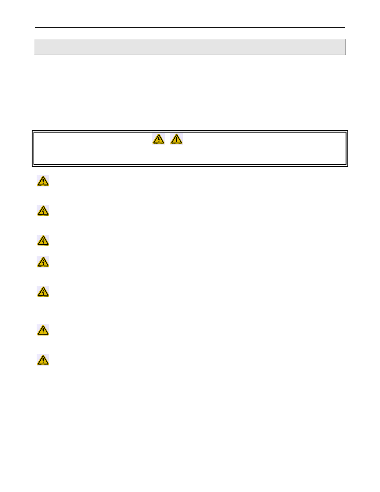
2.1 General Safety Precautions
Please refer to the following safety instructions before and during operation of the system:
Only personnel trained in machine operations must operate the system.
Internal maintenance should only be performed by personnel specifically trained on the
system.
CAUTIONS!
PERSONAL INJURY OR EQUIPMENT DAMAGE MAY RESULT IF THE FOLLOWING
SAFETY PRECAUTIONS AND WARNINGS ARE NOT OBSERVED AT ALL TIMES.
Do not operate the system with the enclosure open. Always turn power and air
supply OFF before opening the enclosure.
Do not disconnect any electrical connections when the system power is on.
Damage to electrical components may occur.
Use lockout/tag-out equipment to prevent injury or damage when servicing the unit.
Before connecting an external device, power down both the TapTone system and the
external device. After power is off, connect device then turn power on.
The internal electronics of this equipment are sensitive to electrostatic discharge
(ESD) and proper precautions must be adhered to when handling any electrical
components of the system.
Do not place radial or axial load on the shaft encoder when mounting to the conveyor.
Internal damage to the encoder disk will occur.
Avoid high pressure spray with aggressive cleaning solvents on components like the
photo triggers, lamps and touch screen display.
TELEDYNE TAPTONE 4
M-412-073 Chapter 2: Safety Precautions
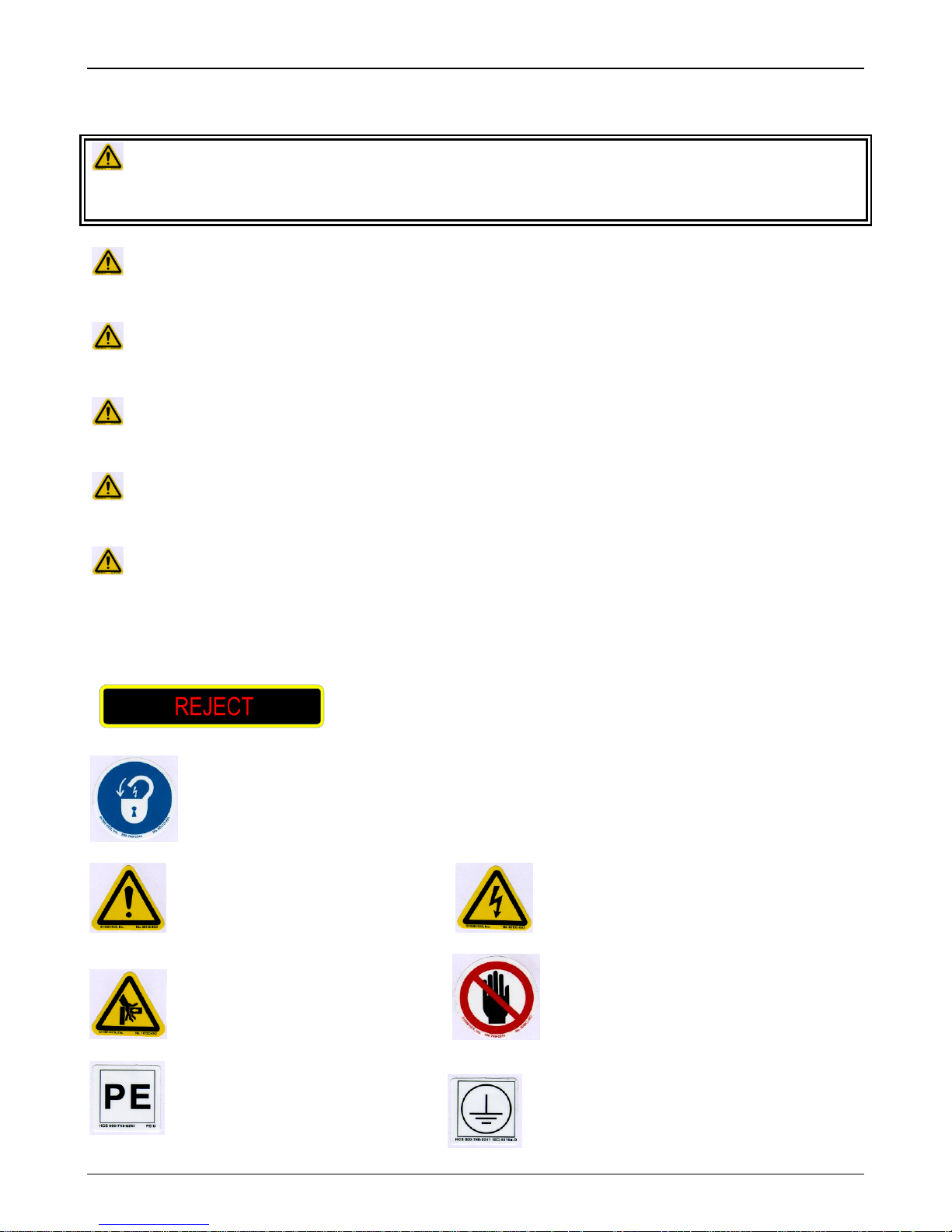
Lock-out electrical power before servicing.
General danger. (see manual)
Hazard electrical shock.
Hazard hand crush.
Stay clear.
Protective Earth.
AC input ground wire
only.
General Chassis Earth Ground.
Denotes reject lamp.
2.2 Specific Cautions and Warnings
WARNINGS! PERSONAL INJURY OR EQUIPMENT DAMAGE MAY RESULT IF THE
FOLLOWING SAFETY PRECAUTIONS AND WARNINGS ARE NOT OBSERVED AT ALL
TIMES.
Do not operate the system with the safety guards open. Failure to do so may cause
severe injury.
Keep hands clear of the rejector ram, conveyor belts and inspection bridges whenever
the system is in operation.
Do not operate this equipment with long hair or baggy loose clothing. Serious injury
may occur if it gets caught in any moving parts.
WARNING! - Keep hands clear of X-ray tunnel when X-ray lamp is on. X-ray energy is
transmitting when the X-ray lamp is ON.
WARNING! - This X-ray system MUST NOT be operated without the tunnel safety
shields installed.
2.3 Safety Label Descriptions
TELEDYNE TAPTONE 5
Figure 2-1 Safety Labels
M-412-073 Chapter 2: Safety Precautions
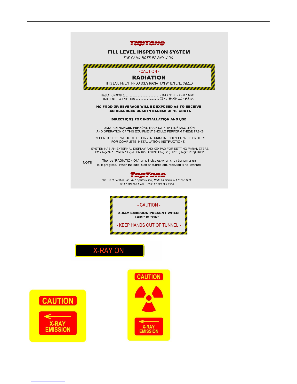
Denotes X-ray lamp.
Indicates X-ray caution
and emission direction.
Standard CE
TELEDYNE TAPTONE 6
Figure 2-2 X-ray Safety Labels
M-412-073 Chapter 2: Safety Precautions
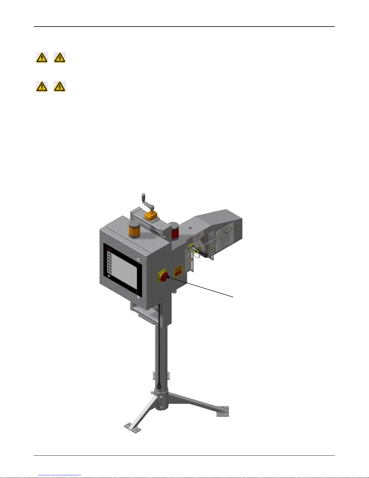
AC Power Switch
2.4 System Lockout / Tag-out Procedure
NOTICE! – Technicians MUST use a Lockout / Tag-out pad lock on each system
power switch whenever service is required
DANGER! – Never remove a pad-lock that was placed on the system by someone
else. Other technicians may be doing service to the system at the same time.
1. Turn the system main power switch to the OFF (0) position for both the inspection
electronics enclosure and the compression belt motor control enclosure.
2. Place a pad-lock through one of the three switch lock loops on both of the power
switches. A maximum of three pad-locks may be place on each switch.
3. Remove your pad-lock once your service is complete to resume normal operations. Do
not remove any other pad-locks that may be place on the system by other technicians as
they may be performing a different service procedure.
Figure 2-3 Lock-out Switch Locations
TELEDYNE TAPTONE 7
M-412-073 Chapter 3: Installation Instructions
3.0 Installation Instructions
3.1 T4000 Sensor Configurations
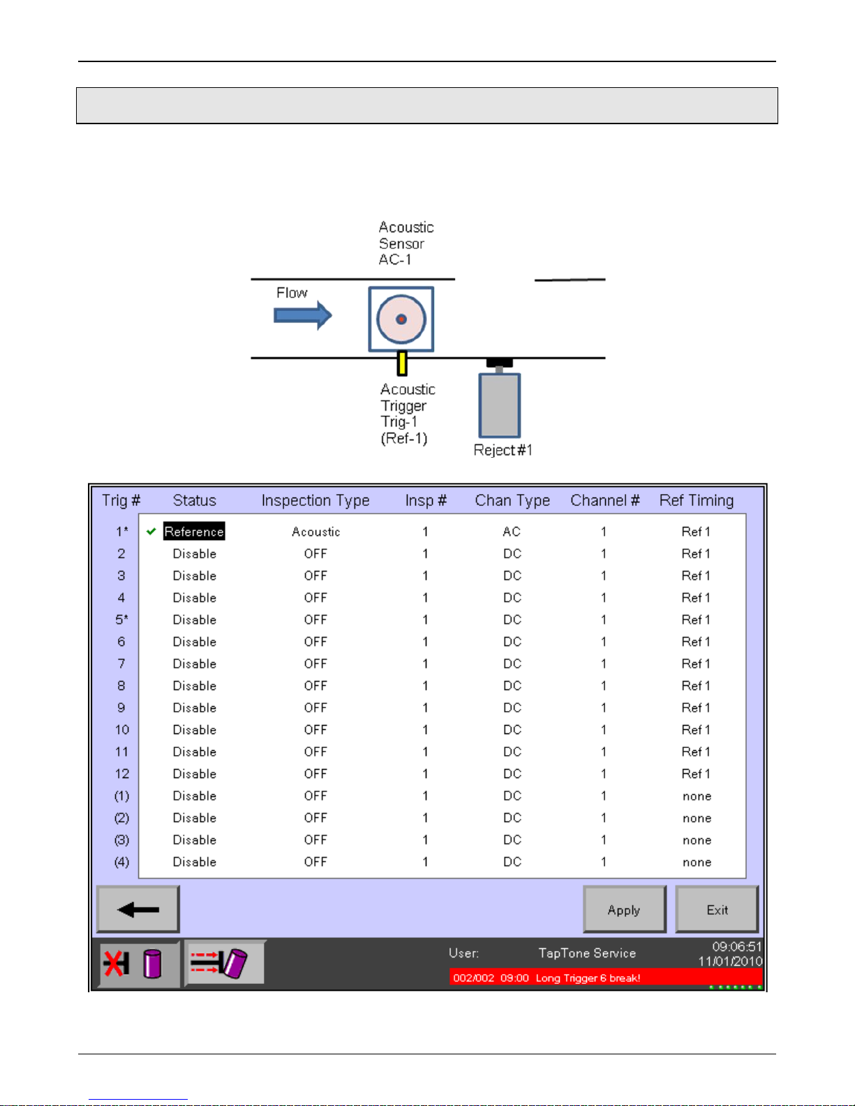
3.1.1 Acoustic Configuration (T4000 A)
TELEDYNE TAPTONE 8
M-412-073 Chapter 3: Installation Instructions
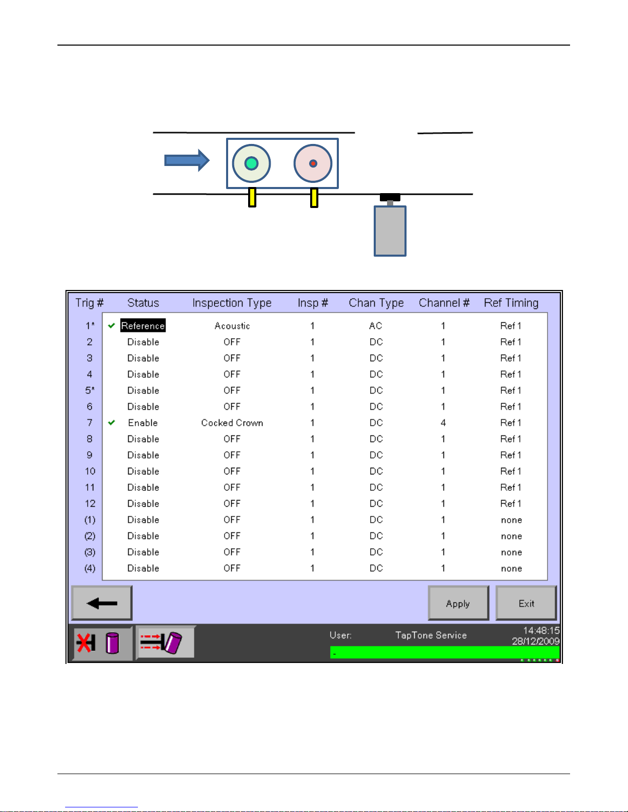
Acoustic
AC-1
Cocked
DC-4
Flow
Acoustic
(Ref-1)
Cocked
Trig-7
Reject #1
3.1.2 Acoustic/Cocked Crown Configuration (T4000 AC)
Crown
Sensor
Sensor
Crown
Trigger
Trigger
Trig-1
TELEDYNE TAPTONE 9
M-412-073 Chapter 3: Installation Instructions
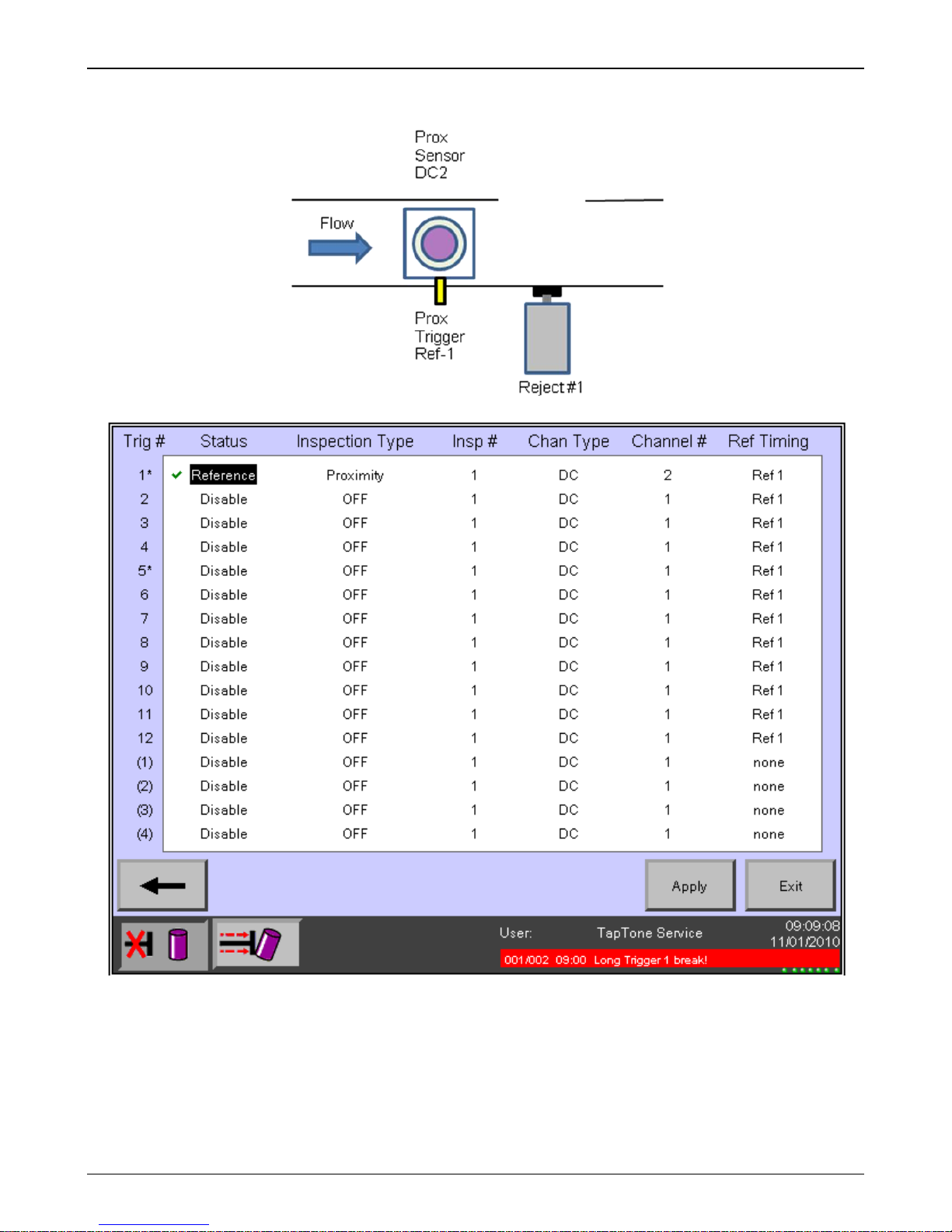
3.1.3 Proximity Configuration (T4000 P)
TELEDYNE TAPTONE 10
 Loading...