

Teledyne SP Devices ADQ14-FWPD, ADQ14 User Manual

ADQ14-FWPD
User Guide
Author(s): Teledyne SP Devices
Document ID: 18-2074
Classification: Public
Revision: PA1
Print date: 2018-04-06

Classification Revision
Public PA1
Document ID Print date
18-2074 2018-04-06
Contents
1 Introduction 3
1.1 Definitions & Abbreviations . . . . . . . . . . . . . . . . . . . . . . . . . . . . . . . . . . . 3
2 Features 3
2.1 Specification . . . . . . . . . . . . . . . . . . . . . . . . . . . . . . . . . . . . . . . . . . . 4
2.2 Overview . . . . . . . . . . . . . . . . . . . . . . . . . . . . . . . . . . . . . . . . . . . . . 4
3 Getting Started 7
3.1 SDK Installation . . . . . . . . . . . . . . . . . . . . . . . . . . . . . . . . . . . . . . . . . 7
3.1.1 Installing the SDK (Windows) . . . . . . . . . . . . . . . . . . . . . . . . . . . . . . 7
3.1.2 Installing the SDK (Linux) . . . . . . . . . . . . . . . . . . . . . . . . . . . . . . . . 7
3.1.3 Unsupported Software Features . . . . . . . . . . . . . . . . . . . . . . . . . . . . 8
3.2 Collecting Data . . . . . . . . . . . . . . . . . . . . . . . . . . . . . . . . . . . . . . . . . . 8
4 Detailed System Description 8
4.1 Digital Baseline Stabilization . . . . . . . . . . . . . . . . . . . . . . . . . . . . . . . . . . 8
4.2 Moving Average . . . . . . . . . . . . . . . . . . . . . . . . . . . . . . . . . . . . . . . . . 8
4.3 Pulse Specification . . . . . . . . . . . . . . . . . . . . . . . . . . . . . . . . . . . . . . . . 9
4.3.1 Edge Windows . . . . . . . . . . . . . . . . . . . . . . . . . . . . . . . . . . . . . . 10
4.3.2 Baseline Tracking . . . . . . . . . . . . . . . . . . . . . . . . . . . . . . . . . . . . 12
4.4 Trigger Features . . . . . . . . . . . . . . . . . . . . . . . . . . . . . . . . . . . . . . . . . 12
4.4.1 Timestamp Reset . . . . . . . . . . . . . . . . . . . . . . . . . . . . . . . . . . . . 12
4.4.2 Trigger Blocking . . . . . . . . . . . . . . . . . . . . . . . . . . . . . . . . . . . . . 13
4.4.3 Synchronization Signals . . . . . . . . . . . . . . . . . . . . . . . . . . . . . . . . . 14
4.5 Coincidence . . . . . . . . . . . . . . . . . . . . . . . . . . . . . . . . . . . . . . . . . . . . 14
4.6 Detection Window . . . . . . . . . . . . . . . . . . . . . . . . . . . . . . . . . . . . . . . . 15
4.7 Data Multiplexer . . . . . . . . . . . . . . . . . . . . . . . . . . . . . . . . . . . . . . . . . 16
4.8 Pulse Characterization . . . . . . . . . . . . . . . . . . . . . . . . . . . . . . . . . . . . . . 16
4.8.1 Pulse Width . . . . . . . . . . . . . . . . . . . . . . . . . . . . . . . . . . . . . . . . 17
4.8.2 Pulse Peak Value . . . . . . . . . . . . . . . . . . . . . . . . . . . . . . . . . . . . 17
4.8.3 Pulse Peak Value Timestamp . . . . . . . . . . . . . . . . . . . . . . . . . . . . . . 17
4.8.4 Overflow . . . . . . . . . . . . . . . . . . . . . . . . . . . . . . . . . . . . . . . . . 17
4.9 Histograms . . . . . . . . . . . . . . . . . . . . . . . . . . . . . . . . . . . . . . . . . . . . 17
4.9.1 Overflow . . . . . . . . . . . . . . . . . . . . . . . . . . . . . . . . . . . . . . . . . 18
4.10 Padding . . . . . . . . . . . . . . . . . . . . . . . . . . . . . . . . . . . . . . . . . . . . . . 19
4.11 User Space Record . . . . . . . . . . . . . . . . . . . . . . . . . . . . . . . . . . . . . . . 19
4.11.1 Fixed Length Record . . . . . . . . . . . . . . . . . . . . . . . . . . . . . . . . . . . 19
4.11.2 Variable Length Record . . . . . . . . . . . . . . . . . . . . . . . . . . . . . . . . . 19
4.12 Data Collection Modes . . . . . . . . . . . . . . . . . . . . . . . . . . . . . . . . . . . . . . 20
4.12.1 Raw Pulse Data . . . . . . . . . . . . . . . . . . . . . . . . . . . . . . . . . . . . . 20
4.12.2 Every Nth Record . . . . . . . . . . . . . . . . . . . . . . . . . . . . . . . . . . . . 20
4.12.3 Pulse Metadata . . . . . . . . . . . . . . . . . . . . . . . . . . . . . . . . . . . . . . 21
4.12.4 Raw Pulse Data with Padding . . . . . . . . . . . . . . . . . . . . . . . . . . . . . . 22
ADQ14-FWPD – User Guide www.teledyne-spdevices.com Page 1 of 28

Classification Revision
Public PA1
Document ID Print date
18-2074 2018-04-06
5 User Application Example 22
5.1 C Example . . . . . . . . . . . . . . . . . . . . . . . . . . . . . . . . . . . . . . . . . . . . 24
5.1.1 Python Scripts . . . . . . . . . . . . . . . . . . . . . . . . . . . . . . . . . . . . . . 24
5.2 Disk Streaming Example . . . . . . . . . . . . . . . . . . . . . . . . . . . . . . . . . . . . . 24
5.3 Pulse Characterization GUI . . . . . . . . . . . . . . . . . . . . . . . . . . . . . . . . . . . 25
6 Troubleshooting 25
6.1 Managing License Files . . . . . . . . . . . . . . . . . . . . . . . . . . . . . . . . . . . . . 25
6.1.1 Reading the DNA . . . . . . . . . . . . . . . . . . . . . . . . . . . . . . . . . . . . 25
6.1.2 Updating the Digitizer License . . . . . . . . . . . . . . . . . . . . . . . . . . . . . 26
ADQ14-FWPD – User Guide www.teledyne-spdevices.com Page 2 of 28

Classification Revision
Public PA1
Document ID Print date
18-2074 2018-04-06
1 Introduction
This document is the user guide for the ADQ14 digitizer running the pulse detection firmware (-FWPD)
option. Equipped with the pulse detection firmware, the ADQ14 digitizer provides the user with sophisticated tools to identify, collect and analyze regions of interest in the data stream in real-time. This relaxes
the requirements on the host computer in terms of sustained bandwidth of the device-to-host interface,
storage space and offline data parsing.
1.1 Definitions & Abbreviations
Table 1 lists the definitions and abbreviations used in this document and provides an explanation for each
entry.
Table 1: Definitions and abbreviations used in this document.
Term Explanation
ADC Analog-to-digital converter
API Application programming interface
DBS Digital baseline stabilization
FWPD Pulse detection firmware for ADQ14
GSPS 109samples per second
GUI Graphical user interface
Horizontal parameters Used to describe parameters and settings which are specified in
samples (SI unit seconds). For example, the length of a record
of data.
LEW Leading edge window
MSPS 106samples per second
TEW Trailing edge window
Vertical parameters Used to describe parameters and settings which are specified in
ADC codes (SI unit Volt). For example, the level trigger threshold.
2 Features
This section presents the specification of ADQ14-FWPD along with brief descriptions of some of its core
features. Detailed information may be found in Section 4. Additionally, information pertaining to the
ADQ14 platform in general and not this firmware specifically may be found in the ADQ14 manual [1].
However, if the documents give conflicting information, this document takes precedence for devices
running this particular firmware option.
ADQ14-FWPD – User Guide www.teledyne-spdevices.com Page 3 of 28

Classification Revision
Public PA1
Document ID Print date
18-2074 2018-04-06
2.1 Specification
The specification for the pulse detection firmware is presented in Table 2. For the general specification
of the ADQ14 digitizer, please refer to the ADQ14 data sheet [2].
Table 2: Specification for ADQ14-FWPD.
Item Min Max Unit
General
Pulse width 1 - Sample
Pulse separation 1 - Sample
Record length (500 MSPS, 1 GSPS) 4 232- 1 Sample
Record length (2 GSPS) 8 232- 1 Sample
Pulse characterization
Pulse width
Pulse peak timestamp
1
2
1 216- 1 Sample
- 232- 1 Sample
Average pulse rate (1 GSPS) - 250 106Pulses / s
Average pulse rate (2 GSPS) - 500 106Pulses / s
Average pulse rate for histograms - 33 106Pulses / s
Histogram bin value - 1 048 575 -
1
See Section 4.8.1
2
See Section 4.8.3
2.2 Overview
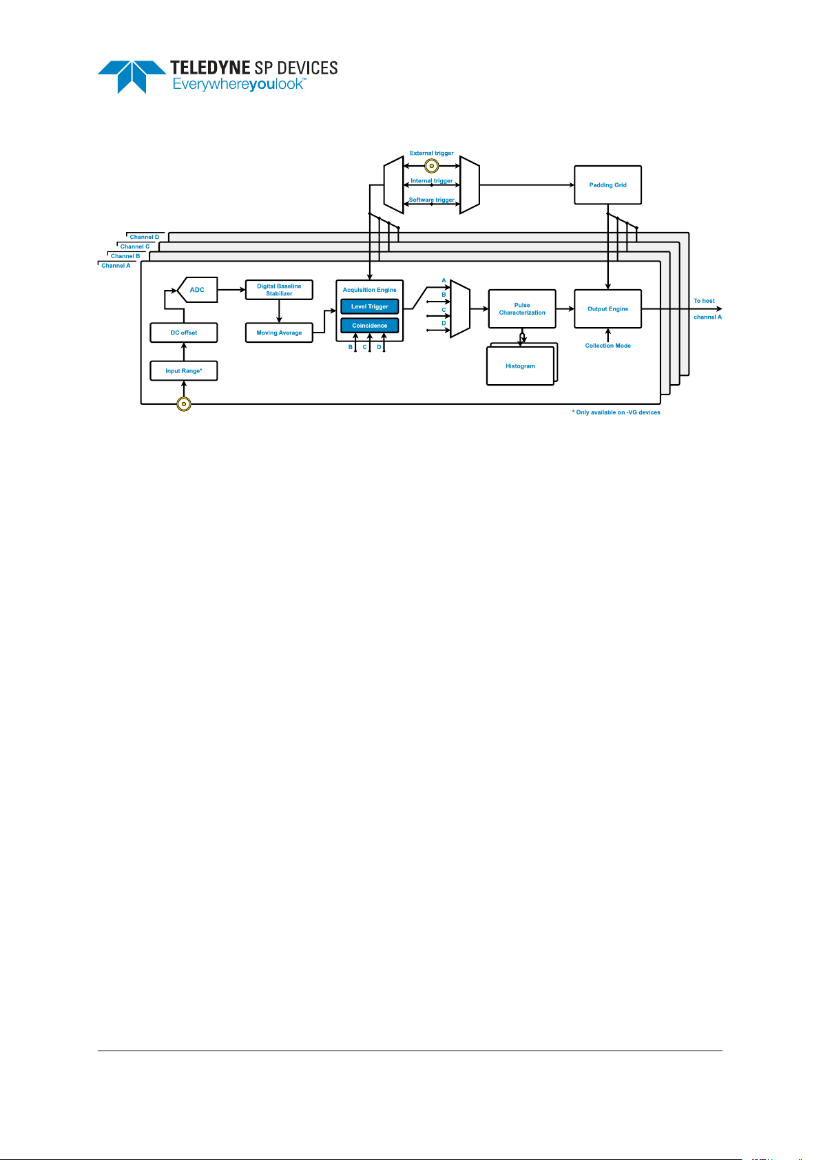
Fig. 1 presents a block diagram outlining the main features of the data path. The diagram is drawn for a
four-channel device but applies to one- and two-channel devices as well.
• Input range
ADQ14 digitizers with the –VG option offer the possibility to tune the input range of the digitizer.
• DC offset
The analog signal may be subjected to a DC offset. If only pulses with a certain polarity is expected,
the user may wish to offset the analog signal to place the baseline close to the maximum or minimum
ADC code. This allows pulses with amplitudes that would normally saturate the ADC to be safely
collected, thus increasing the dynamic range of the digitizer.
• ADC
The analog signal is sampled at 500 MSPS (–A devices), at 1 GSPS (–C devices) or at 2 GSPS
(–X devices).
ADQ14-FWPD – User Guide www.teledyne-spdevices.com Page 4 of 28
Classification Revision
Public PA1
Document ID Print date
18-2074 2018-04-06
Figure 1: A block diagram presenting the main features of the ADQ14-FWPD data path.
• Digital baseline stabilizer
The digital baseline stabilizer (DBS) provides a highly accurate and stable baseline, specifically
intended for pulse applications. Additional information on the DBS is provided in Section 4.1.
• Moving average
The moving average function tracks the baseline of the signal using a configurable window looking
at the last 100 samples. Tracking the baseline allows the user to input the pulse specification relative to the baseline rather than in absolute ADC codes. The moving average function is discussed
further in Section 4.2.
• Acquisition engine
The acquisition engine is tasked with creating records of data. Each channel is configured independently and requires a trigger condition and a specification of the horizontal parameters.
– Trigger
The trigger condition may be selected from one of the three global trigger sources: external
trigger, internal trigger or software trigger. The latter is mainly used for debugging purposes
and has limited practical application. In this case, the selected source is shared among all
channels using the global trigger source. Another option is to use the level trigger, in which
case each channel operates independently since the trigger condition is detected by analyzing
the local data stream. The ways to trigger a record are discussed throughout Section 4,
particularly in Sections 4.4, 4.6 and 4.11.
– Coincidence
The coincidence function allows the user to impose additional conditions to the trigger mechanism. Each channel has a configurable logic OR expression which needs to evaluate to true in
order for a record to be generated from a trigger event. An example of a coincidence condition
is provided below.
ADQ14-FWPD – User Guide www.teledyne-spdevices.com Page 5 of 28

Classification Revision
Public PA1
Document ID Print date
18-2074 2018-04-06
Example
“A trigger on channel A should be accepted and create a record if channel B has detected
a trigger in the last 100 ns.”
In addition to the trigger condition and coincidence masking, the definition of a region of interest
may be refined further by using a detection window (Section 4.6). This window defines a period in
time during which pulses are accepted for analysis. Any pulses outside of the window are rejected
and are prevented from propagating to the user.
• Data multiplexer
The data multiplexer allows the user to select which data stream to input to the pulse characterization process. In this way, the data collection modes (discussed in Section 4.12) make it possible to
verify the system by observing the raw pulse data together with its corresponding metadata. The
data multiplexer is discussed in Section 4.7.
• Pulse characterization
The pulse characterization function offers real-time analysis of the pulse data where three key
metrics are extracted: the peak value, the width (time-over-threshold) and the time of the peak value
relative to the trigger timestamp. The pulse metadata format is described in detail in Section 4.12.3.
Additionally, the metadata collection mode (discussed in Section 4.12) allows the user to reduce
the output data rate further by choosing to only output the pulse metadata.
• Histogram
The pulse peak value and width are forwarded to two independent histograms which are tasked
with keeping track of the frequency of occurrence of events of a certain type. Details on the histogramming feature may be found in Section 4.9.
• Padding grid
The padding grid defines a window in time which acts as a guide when the digitizer inserts padding
data. This padding data is required in applications which require a certain minimum activity regardless of the event frequency while still maintaining a high throughput capacity of the device-to-host
interface.
Inserting padding data into the data stream introduces overhead and thus lowers the effective
bandwidth of the device-to- host interface (the bandwidth used to transfer useful data). This is
an inevitable consequence since the concept of padding targets the trade-off between throughput
and latency. The goal is to provide the user with the tools needed to find a balanced compromise between the application’s requirements. The padding mechanism is described in detail in
Section 4.10.
• Output engine
The output engine offers flexible control over the flow of data. There are five different data collection
modes ranging from only pulse metadata to raw pulse data with padding. The output engine is
described in detail in Section 4.12.
ADQ14-FWPD – User Guide www.teledyne-spdevices.com Page 6 of 28

Classification Revision
Public PA1
Document ID Print date
18-2074 2018-04-06
3 Getting Started
This section provides information on how to interface with ADQ14 and the pulse detection firmware.
Table 3 describes the peripherals and their usage.
Table 3: Peripheral connections on ADQ14.
Connector Description
TRIG External trigger input/output
SYNC Synchronization input/output
A Channel A input (one, two and four-channel devices)
B Channel B input (two and four-channel devices)
C Channel C input (four-channel devices)
D Channel D input (four-channel devices)
CLK External reference clock input
3.1 SDK Installation
The Software Development Kit (SDK) contains the ADQAPI, drivers, examples and documentation required tor successfully interface with the digitizer. The installation procedure for Microsoft Windows and
Linux is described in the following sections.
3.1.1 Installing the SDK (Windows)
For Microsoft Windows the SDK is installed by running
ADQ-setup_rXXXXX.exe
where XXXXX is the version number. After the installation the example code is located in
<Path to installation directory>/C_examples/
and the documentation in
<Path to installation directory>/Documentation/
3.1.2 Installing the SDK (Linux)
The SDK is supported for a number of Linux distributions and versions. The required files are all included
in
ADQ_SDK_linux_rXXXXX.tar.gz
where XXXXX is the version number. The archive contains the SDK installation files, example code and
documentation. The README file, located in the root directory of the archive, describes the installation
ADQ14-FWPD – User Guide www.teledyne-spdevices.com Page 7 of 28

Classification Revision
Public PA1
Document ID Print date
18-2074 2018-04-06
procedure in detail for the different distributions.
3.1.3 Unsupported Software Features
Listed below are the features supported by ADQ14 which are not supported by ADQ14-FWPD,
• ADCaptureLab
• LabView API
3.2 Collecting Data
The FWPD C example is provided together with the SDK. For Windows it is located in
<Path to installation directory>/C_examples/ADQAPI_FWPD_example
after installing the SDK, and for Linux in the
examples/ADQAPI_FWPD_example
directory of the SDK archive. This example illustrates the capabilities of ADQ7-FWPD, and can be used
as-is. However, the example is primarily intended to be used as a guide for creating applications tailored
to a specific use case.
4 Detailed System Description
This section provides additional details on important system features.
4.1 Digital Baseline Stabilization
For optimal performance in pulse applications, it is advantageous if the baseline of the signal is locked
to a specific value. This is the purpose of the Digital Baseline Stabilizer (DBS). The signal processing
block is placed directly after the ADC in the data path.
The DBS uses a blind identification process operating in the background. When activated by the user,
DBS will constantly monitor and follow variations in the baseline and correct for time-varying behavior
such as temperature variations. The baseline is adjusted to the target value with 22-bit precision.
4.2 Moving Average
The moving average function computes an average of samples earlier in time using a memory with
capacity to store the previous 100 samples. From this data set, the user can select a range of samples
which should be used to compute the moving average value attributed to the current sample. The range
is specified as a window which has a length and an offset from the current sample. Both the length and
the offset may be given in the range from 0 to 100 samples. However, the sum of the two parameters
may not exceed 100 samples.
ADQ14-FWPD – User Guide www.teledyne-spdevices.com Page 8 of 28
 Loading...