

TELEDYNE RELAYS RF300, RF303 Technical data
RF & MICROWAVE
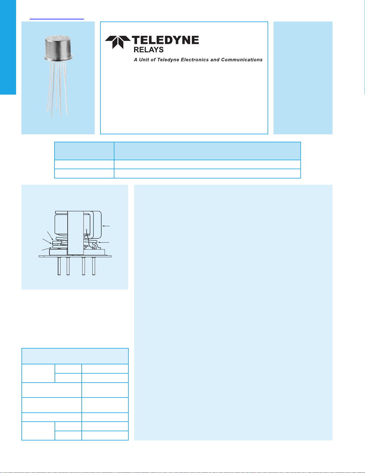
UPPER
STATIONARY
CONTACT
MOVING
CONTACT
LOWER
STATIONARY
CONTACT
UNI-FRAME
ARMATURE
查询RF300供应商
SERIES
RF300
HIGH REPEATABILITY
RF303
BROADBAND
TO-5 RELAYS
DPDT
SERIES
DESIGNATION
RF300 Repeatable RF relay
RF303 Sensitive, repeatable RF relay
INTERNAL CONSTRUCTION
RELAY TYPE
PERFORMANCE FEATURES
The ultraminiature RF300 and RF303 relays are designed to provide improved
RF signal repeatability over the frequency range. These relays are highly
suitable for use in attenuator and other RF circuits, the RF 300 and RF303
feature:
• High repeatability.
• Broader bandwidth.
• Metal enclosure for EMI shielding.
• Ground pin option to improve case grounding.
• High isolation between control and signal paths.
• Highly resistant to ESD.
CONSTRUCTION FEATURES
The following unique construction features and manufacturing techniques
provide excellent resistance to environmental extremes and overall high
reliability.
ENVIRONMENTAL AND
PHYSICAL SPECIFICATIONS
Temperature
(Ambient)
Vibration
(General Note 1)
Shock
(General Note 1)
Enclosure Hermetically sealed
Weight
©2003 TELEDYNE RELAYS SPECIFICATIONS ARE SUBJECT TO CHANGE WITHOUT NOTICE RF300 RF303 Page 26
Storage –65°C to +125°C
Operating –55°C to +85°C
10 g’s to 500 Hz
30 g’s,
6 msec, half-sine
RF300 0.09 oz. (2.55g) max.
RF303 0.16 oz. (4.5g) max.
• Uni-frame motor design provides high magnetic efficiency and mechanical
rigidity.
• Minimum mass components and welded construction provide maximum
resistance to shock and vibration.
• Advanced cleaning techniques provide maximum assurance of internal
cleanliness.
• Gold-plated precious metal alloy contacts ensure reliable switching.
• Hermetically sealed.
• Solderable leads.
www.teledynerelays.com RF300 RF303/1203/Q1
SERIES RF300 AND RF303
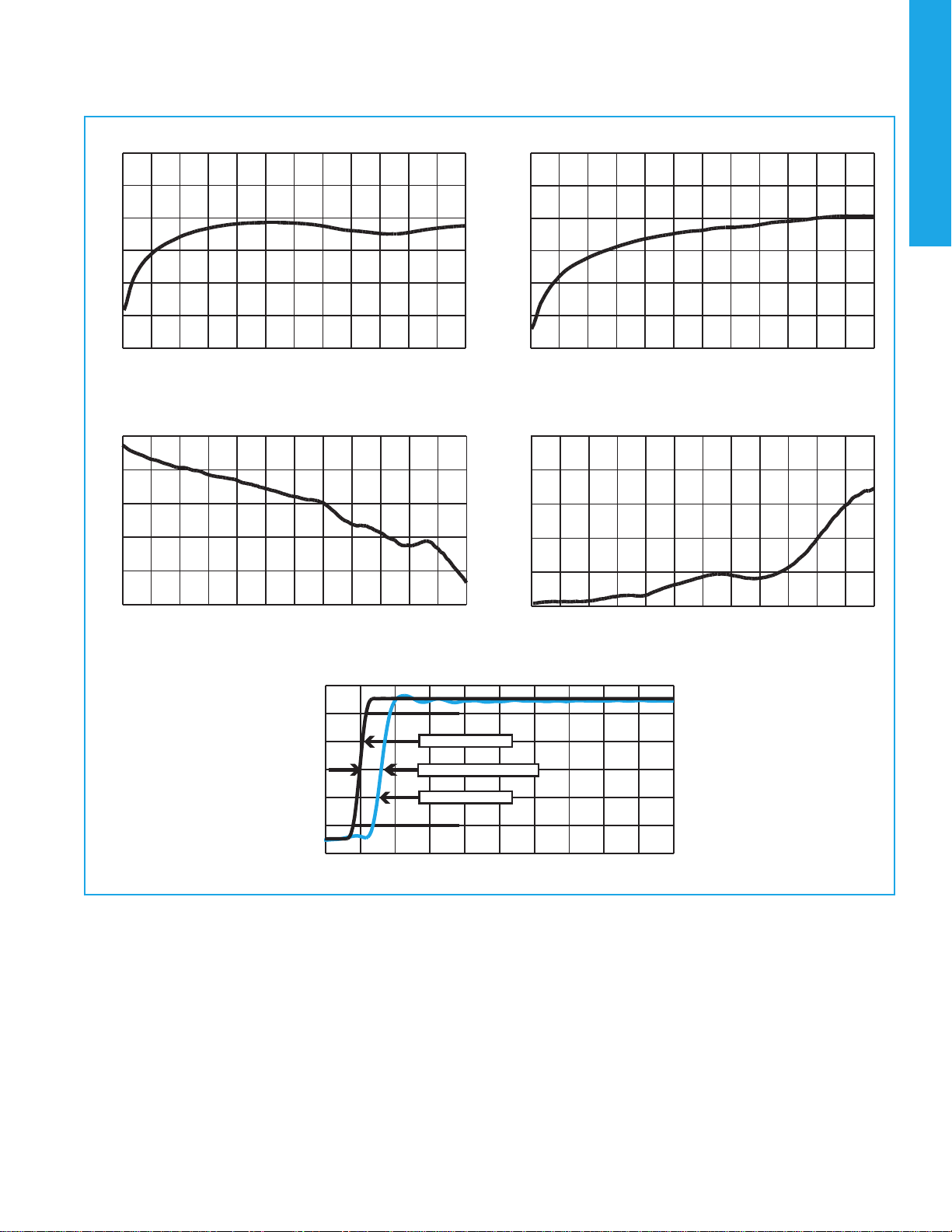
Isolation Across Contacts (RF Note 4)
-60
-50
-40
-30
-20
-10
0
0 500 1000 1500 2000 2500 3000 3500 4000 4500 5000 5500 6000
Frequency (MHz)
Isolation (dB)
Isolation Pole to Pole (RF Note 5)
-60
-50
-40
-30
0
-10
-20
0 500 1000 1500 2000 2500 3000 3500 4000 4500 5000 5500 6000
Frequency (MHz)
Isolation (dB)
Insertion Loss (RF Note 6)
-1
-0.8
-0.6
-0.4
-0.2
0
0 500 1000 1500 2000 2500 3000 3500 4000 4500 5000 5500 6000
Frequency (MHz)
Insertion Loss (dB)
VSWR (RF Note 6)
1.0
1.2
1.4
1.6
1.8
2.0
0 500 1000 1500 2000 2500 3000 3500 4000 4500 5000 5500 6000
Frequency (MHz)
VSWR
RF300 Time Response (RF Note 6)
-0.1
0.1
0.3
0.5
0.7
0.9
1.1
-100 0 100 200 300 400 500 600 700 800 900
Time (ps)
Volt
10%
90%
37ps reference
51.1ps pulse rise time
62.3ps propagation delay time
TYPICAL RF CHARACTERISTICS (See RF Notes)
RF & MICROWAVE
RF NOTES
1. Test conditions: a. Fixture: .031" copper clad, reinforced PTFE, RT/duroid®6002 with SMA connectors. (RT/duroid®is a
registered trademark of Rogers Corporation.)
b. Room ambient temperature.
c. Terminals not tested were terminated with 50-ohm load.
d. Contact signal level: –10 dBm.
e. No. of test samples: 4.
2. Data presented herein represents typical characteristics and is not intended for use as specification limits.
3. Data is per pole, except for pole-to-pole data.
4. Data is the average from readings taken on all open contacts.
5. Data is the average from readings taken on poles with coil energized and de-energized.
6. Data is the average from readings taken on all closed contacts.
7. Test fixture effect de-embedded from frequency and time response data.
RF300 RF303 Page 27 SPECIFICATIONS ARE SUBJECT TO CHANGE WITHOUT NOTICE ©2003 TELEDYNE RELAYS
www.teledynerelays.com RF300 RF303/1203/Q1
 Loading...